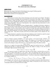
Page 4 <strong>of</strong> 6Figure 3-1 A force table, with it’s top shown vertically for demonstration. In <strong>the</strong> laboratory, <strong>the</strong> table willbe horizontal, <strong>and</strong> a more compact style <strong>of</strong> pulley clamp will be used.For F2, attach a pulley clamped at 120° relative to <strong>the</strong> right horizontal, <strong>and</strong> a string <strong>and</strong> weight hook tiedto <strong>the</strong> center table ring. Once again, as indicated below, when you are ready to perform <strong>the</strong>experimental force analysis, you will place two 200 gram weights on <strong>the</strong> weight hook yielding a totalmass <strong>of</strong> 250 grams (0.250kg) yielding a force <strong>of</strong> approximately 2.45 N.<strong>The</strong> resultant <strong>of</strong> two or more force vectors is found by balancing <strong>the</strong> forces with ano<strong>the</strong>r force attachedto <strong>the</strong> ring centered on <strong>the</strong> central pin. <strong>The</strong> balancing force is not <strong>the</strong> resultant vector FR. Ra<strong>the</strong>r, it is<strong>the</strong> “equilibrant” force vector E, <strong>the</strong> force that balances <strong>the</strong> resultant <strong>of</strong> <strong>the</strong> o<strong>the</strong>r forces holding <strong>the</strong> ringin equilibrium.<strong>The</strong> equilibrant vector E is <strong>the</strong> vector force <strong>of</strong> equal magnitude, but <strong>the</strong> opposite direction (i.e.,displaced 180°) <strong>of</strong> <strong>the</strong> resultant force FR. Accordingly,or,E = -FRFR = -E = |E|/ θE° + 180 0(note <strong>the</strong> addition <strong>of</strong> 180 0 . Why is this needed?)Clamp a pulley at <strong>the</strong> angle 180° from <strong>the</strong> angle you believe you will find <strong>the</strong> resultant vector FR. Add astring <strong>and</strong> a hook <strong>and</strong> drape it over <strong>the</strong> pulley. At this point, add masses to <strong>the</strong> hooks for F1 <strong>and</strong> F2 asappropriate. Now add masses to <strong>the</strong> hook associated with force E, until <strong>the</strong> system appears to bebalanced around <strong>the</strong> pin on <strong>the</strong> table. <strong>The</strong> ring should be able to sit on <strong>the</strong> center <strong>of</strong> <strong>the</strong> table without<strong>the</strong> support <strong>of</strong> <strong>the</strong> pin. When your system is in balance, record <strong>the</strong> mass <strong>of</strong> <strong>the</strong> equilibrant <strong>and</strong>determine <strong>the</strong> weight associated with that mass. This weight produces <strong>the</strong> equilibrant force vector E.Draw this vector E on your graphical solution. Using vector E, determine vector FR.Place your graphical, analytical, <strong>and</strong> experimental results in <strong>Table</strong> 3-1.Show your force table results to <strong>the</strong> lab instructor for verification <strong>and</strong>/or corrections.
Page 5 <strong>of</strong> 63.2) Vector <strong>Addition</strong> #2 – In <strong>the</strong> second addition you will be adding two vectors,<strong>and</strong>,F 1 = m 1·g / θ1° = (0.200 kg)·( 9.8m/s 2 ) / 20° = 1.96N / 20°F 2 = m 2·g / θ2° = (0.150 kg)·( 9.8m/s 2 ) /80° = 1.47N / 80° .for <strong>the</strong>se values <strong>of</strong> F1 <strong>and</strong> F2, repeati) <strong>the</strong> graphical “tail-to-tip” analysis <strong>of</strong> section 3.1.1ii) <strong>the</strong> h<strong>and</strong> analysis <strong>of</strong> section 3.1.2, <strong>and</strong>,iii) adjust masses <strong>and</strong> use <strong>the</strong> experimental force table analysis <strong>of</strong> section 3.1.3.Enter your results in <strong>Table</strong> 3-1 as appropriate.3.3) Vector <strong>Addition</strong> #3 – In <strong>the</strong> third addition you will be adding three vectors,<strong>and</strong>,<strong>and</strong>,F 1 = m 1·g / θ1° = (0.100 kg)·( 9.8m/s 2 ) / 30° = 0.980N / 30° ,F 2 = m 2·g / θ2° = (0.200 kg)·( 9.8m/s 2 ) /90° = 1.96N / 90° , <strong>and</strong>,F 3 = m 3·g / θ3° = (0.300 kg)·( 9.8m/s 2 ) /330° = 2.94N / 330° .Find <strong>the</strong> resultant force vector FR, brought about by <strong>the</strong> addition <strong>of</strong> <strong>the</strong>se three vectors <strong>using</strong>:i) <strong>the</strong> graphical “tip to tail” analysis <strong>of</strong> section 3.1.1ii) <strong>the</strong> h<strong>and</strong> analysis <strong>of</strong> section 3.1.2, <strong>and</strong>,iii) <strong>the</strong> experimental force table analysis <strong>of</strong> section 3.1.3.Enter your results in <strong>Table</strong> 3-1 as appropriate.3.4) Vector <strong>Resolution</strong> – You are given a force vector <strong>of</strong>F = m 1·g / θ1° = (0.300 kg)·( 9.8m/s 2 ) / 60° = 2.94N / 60° .Note: This problem is not <strong>the</strong> same as <strong>the</strong> previous examples. You are given a single force <strong>and</strong> willcalculate <strong>the</strong> x <strong>and</strong> y components <strong>of</strong> <strong>the</strong> vector. You will <strong>the</strong>n determine <strong>the</strong> equilibrant vectors to each<strong>of</strong> <strong>the</strong> two components to see if it balances <strong>the</strong> single original force. You will resolve this vector into its x<strong>and</strong> y components, (i.e., F X <strong>and</strong> F Y ) with <strong>the</strong> following procedures:3.4.1) Graphical <strong>Resolution</strong> <strong>of</strong> a Vector - Draw F on a Cartesian coordinate system drawn on apiece <strong>of</strong> paper <strong>using</strong> a rule <strong>and</strong> protractor <strong>using</strong> a scale <strong>of</strong> 0.4 N per cm ( 0.4 Newtons percentimeter). Label it with its symbolic name, F as indicated above. Drop a vertical to <strong>the</strong> x axisfrom <strong>the</strong> tip <strong>of</strong> <strong>the</strong> vector arrowhead. <strong>The</strong> displacement along <strong>the</strong> x axis is <strong>the</strong> horizontalcomponent Fx; measure it with your rule <strong>and</strong> use your scaling factor t determine it value inNewtons . Draw a horizontal from <strong>the</strong> y axis to <strong>the</strong> arrowhead; <strong>the</strong> displacement along <strong>the</strong> yaxis is <strong>the</strong> vertical component Fy; once again determine it with a rule <strong>and</strong> your scaling factor.Label <strong>the</strong> upper right corner with your name <strong>and</strong> “Vector <strong>Resolution</strong> Example”3.4.2) Analytical Analysis – Compute Fx <strong>and</strong> Fy by ma<strong>the</strong>matically calculating <strong>the</strong> x <strong>and</strong> ycomponents <strong>of</strong> vector F.3.4.3) Experimental Analysis – Clamp pulleys at 60°, 180°, <strong>and</strong> 270° on <strong>the</strong> force table. Place a total<strong>of</strong> about 300 grams (0.300 kg) on <strong>the</strong> 60° weight hanger including <strong>the</strong> hanger; this is force F.Place weights on <strong>the</strong> 180° hanger <strong>and</strong> <strong>the</strong> 270° hanger until <strong>the</strong> system is in equilibrium. <strong>The</strong>force at 180° is <strong>the</strong> equilibrant <strong>of</strong> Fx; that is to say Fx has <strong>the</strong> same magnitude but points in <strong>the</strong>opposite direction, 0°. <strong>The</strong> force at 270° is <strong>the</strong> equilibrant <strong>of</strong> Fy; Fy has <strong>the</strong> same magnitudebut points in <strong>the</strong> opposite direction, 90°.Enter your Fx <strong>and</strong> Fy component magnitudes from all three methods in <strong>Table</strong> 3-1.Show your force table results to <strong>the</strong> lab instructor for verification <strong>and</strong>/or corrections.