The Addition and Resolution of Force Vectors using the Force Table
The Addition and Resolution of Force Vectors using the Force Table
The Addition and Resolution of Force Vectors using the Force Table

You also want an ePaper? Increase the reach of your titles
YUMPU automatically turns print PDFs into web optimized ePapers that Google loves.
Page 1 <strong>of</strong> 6Print <strong>the</strong>se lab instructions before coming to lab.You will need to use all your lab time to do <strong>the</strong> solutions below.Lab #7<strong>The</strong> <strong>Addition</strong> <strong>and</strong> <strong>Resolution</strong> <strong>of</strong> <strong>Force</strong> <strong>Vectors</strong><strong>using</strong> <strong>the</strong> <strong>Force</strong> <strong>Table</strong>Physics 107, Spring 2014Note: Follow <strong>the</strong> Vector <strong>Addition</strong>#1 sample for <strong>the</strong> Vector<strong>Addition</strong>#2 <strong>and</strong> Vector <strong>Addition</strong>#3 Examples.Student:Partner 1:Partner 2:Partner 3:________________________________________________________________________________________________________________________Lab Date: ________________________Due Date: ____________________________
Page 2 <strong>of</strong> 6<strong>The</strong> <strong>Addition</strong> <strong>and</strong> <strong>Resolution</strong> <strong>of</strong> <strong>Force</strong> <strong>Vectors</strong> <strong>using</strong> <strong>the</strong> <strong>Force</strong> <strong>Table</strong>1.0) Introduction: In this lab, you will use <strong>the</strong> graphical “tip to tail method” to calculate <strong>the</strong> resultantvector coming from <strong>the</strong> addition <strong>of</strong> two or more vectors. <strong>The</strong> resultant vector will also be calculatedma<strong>the</strong>matically by resolving each force vector into its X <strong>and</strong> Y components <strong>and</strong> adding <strong>the</strong>m to get<strong>the</strong> resultant vector.2.0) Equipment:1) Welch force table2) force table pulleys3) force table center ring4) force table center pin5) roll pulley string (length as needed)6) weight hooks, (50 g hook base)7) 100 g weights8) 50 g weights9) assortment <strong>of</strong> additional 100, 50, 20, 10, <strong>and</strong> 5 gram weights10) sheets paper for diagrams11) circular or semi-circular protractor12) cm rule, <strong>and</strong>13) calculator, pencils, <strong>and</strong> loose leaf paper as needed3.0) Procedure:3.0.1) Leveling <strong>of</strong> force table - Check to see <strong>of</strong> your force table is level. Make any neededadjustments by means <strong>of</strong> leveling screws at <strong>the</strong> base <strong>of</strong> <strong>the</strong> table.All force vectors angles will be referenced to <strong>the</strong> right horizontal, or “0 0 St<strong>and</strong>ard PositionAngle” as discussed in lecture. All angles will be measured in a counter-clockwise direction from<strong>the</strong> right horizontal <strong>and</strong> will be assigned a positive angle.3.0.2) Symbology - Any vector which has yet to be resolved into its x <strong>and</strong> y components will belabeled with <strong>the</strong> following notation for <strong>the</strong> magnitude <strong>and</strong> direction <strong>of</strong> <strong>the</strong> vector. A force vector<strong>of</strong> 3920 Newtons pointing 30° above <strong>the</strong> left horizontal, would be represented as:F = 3920 N / 150°In word processing text, a force vector symbol is shown in boldface with <strong>the</strong> st<strong>and</strong>ard positionangle underlined. On h<strong>and</strong>-drawn diagrams or h<strong>and</strong> written analysis you can place a smallarrow above <strong>the</strong> vector symbol to emphasize that it is a vector.Example: F<strong>The</strong> magnitude <strong>of</strong> <strong>the</strong> force exerted by any one hook <strong>and</strong> weight combination will be calculated as:f = ma y = mgwhere, m is <strong>the</strong> mass <strong>of</strong> <strong>the</strong> weights <strong>and</strong> hook in kg (kilograms),g is <strong>the</strong> uniform acceleration constant <strong>of</strong> near-earth, 9.8 m/s 2 , <strong>and</strong>f is <strong>the</strong> force in N, Newtons, or kg-m/s 2 .
Page 3 <strong>of</strong> 63.1) Vector <strong>Addition</strong> #1 – In <strong>the</strong> first addition we will be adding two vectors,<strong>and</strong>,F 1 = m 1·g / θ1° = (0.250 kg)·( 9.80 m/s 2 ) / 30° = 2.45 N / 30°F 2 = m 2·g / θ2° = (0.250 kg)·( 9.80 m/s 2 ) /120° = 2.45 N / 120° .3.1.1) Graphical Analysis #1: “Tail to Tip” graphical analysis – Draw F 1 on a Cartesian coordinatesystem drawn on a piece <strong>of</strong> paper <strong>using</strong> a rule <strong>and</strong> protractor <strong>using</strong> a scale <strong>of</strong> 0.4 N per cm ( 0.4Newtons per centimeter). Label it with it’s symbolic name, F 1 <strong>and</strong> include <strong>the</strong> magnitude <strong>and</strong>direction as shown above. Now, at <strong>the</strong> tip <strong>of</strong> <strong>the</strong> arrowhead <strong>of</strong> <strong>the</strong> first vector, draw <strong>the</strong> secondvector to <strong>the</strong> same scale. Label F 2 in a similar fashion.Create <strong>the</strong> resultant vector by drawing a vector from <strong>the</strong> tail <strong>of</strong> <strong>the</strong> first vector to <strong>the</strong> arrowhead<strong>of</strong> <strong>the</strong> second vector. Label it F R <strong>and</strong> determine <strong>the</strong> F R vector by measuring its length <strong>and</strong>multiplying it by <strong>the</strong> scale <strong>of</strong> 0.4N/cm. Measure its st<strong>and</strong>ard position angle (relative to righthorizontal) with a protractor.Label <strong>the</strong> upper right corner with your name <strong>and</strong> “Vector Analysis #1.”3.1.2) Analytical Analysis – In a relatively open area on your “Vector Analysis #1” paper, show <strong>the</strong>vector addition <strong>of</strong> <strong>the</strong>se two force vectors by converting each vector into its x <strong>and</strong> ycomponents. Neatly create an organized table that includes each vector <strong>and</strong> it’s correspondingx <strong>and</strong> y components. Use row <strong>and</strong>/or column headings to clearly label all values. Add <strong>the</strong> x <strong>and</strong>y components <strong>of</strong> F1 <strong>and</strong> F2 to find <strong>the</strong> x <strong>and</strong> y components <strong>of</strong> your resultant vector, FR. Neatlycalculate <strong>the</strong> magnitude <strong>and</strong> direction <strong>of</strong> FR as we have previously done. Clearly label this resultappropriately.3.1.3) Experimental Analysis – Set a center pin in <strong>the</strong> receptacle on <strong>the</strong> center <strong>of</strong> <strong>the</strong> force table(see Fig. 3-1 on <strong>the</strong> next page). Place a ring over <strong>the</strong> pin so that it lays flat on <strong>the</strong> table. For F1,clamp a pulley at 30° relative to <strong>the</strong> right horizontal. Tie a long enough pulley string between <strong>the</strong>50 g weight hook <strong>and</strong> <strong>the</strong> center ring to drape <strong>the</strong> hook appropriately over <strong>the</strong> pulley as shownbelow. When you are ready to perform <strong>the</strong> experimental force analysis as indicated below, youwill place two 100 g weights on <strong>the</strong> weight hook yielding a total mass <strong>of</strong> approximately 250 g(0.250 kg) yielding a force <strong>of</strong> 2.45 Newtons. Use <strong>the</strong> actual total mass for your weightcalculation. You will ignore <strong>the</strong> mass <strong>and</strong> weight <strong>of</strong> <strong>the</strong> ring <strong>and</strong> string. Do not place <strong>the</strong> 100 gweights on <strong>the</strong> hook now, wait until instructed to do so in <strong>the</strong> next steps.
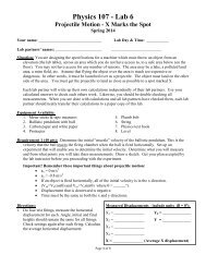
Page 4 <strong>of</strong> 6Figure 3-1 A force table, with it’s top shown vertically for demonstration. In <strong>the</strong> laboratory, <strong>the</strong> table willbe horizontal, <strong>and</strong> a more compact style <strong>of</strong> pulley clamp will be used.For F2, attach a pulley clamped at 120° relative to <strong>the</strong> right horizontal, <strong>and</strong> a string <strong>and</strong> weight hook tiedto <strong>the</strong> center table ring. Once again, as indicated below, when you are ready to perform <strong>the</strong>experimental force analysis, you will place two 200 gram weights on <strong>the</strong> weight hook yielding a totalmass <strong>of</strong> 250 grams (0.250kg) yielding a force <strong>of</strong> approximately 2.45 N.<strong>The</strong> resultant <strong>of</strong> two or more force vectors is found by balancing <strong>the</strong> forces with ano<strong>the</strong>r force attachedto <strong>the</strong> ring centered on <strong>the</strong> central pin. <strong>The</strong> balancing force is not <strong>the</strong> resultant vector FR. Ra<strong>the</strong>r, it is<strong>the</strong> “equilibrant” force vector E, <strong>the</strong> force that balances <strong>the</strong> resultant <strong>of</strong> <strong>the</strong> o<strong>the</strong>r forces holding <strong>the</strong> ringin equilibrium.<strong>The</strong> equilibrant vector E is <strong>the</strong> vector force <strong>of</strong> equal magnitude, but <strong>the</strong> opposite direction (i.e.,displaced 180°) <strong>of</strong> <strong>the</strong> resultant force FR. Accordingly,or,E = -FRFR = -E = |E|/ θE° + 180 0(note <strong>the</strong> addition <strong>of</strong> 180 0 . Why is this needed?)Clamp a pulley at <strong>the</strong> angle 180° from <strong>the</strong> angle you believe you will find <strong>the</strong> resultant vector FR. Add astring <strong>and</strong> a hook <strong>and</strong> drape it over <strong>the</strong> pulley. At this point, add masses to <strong>the</strong> hooks for F1 <strong>and</strong> F2 asappropriate. Now add masses to <strong>the</strong> hook associated with force E, until <strong>the</strong> system appears to bebalanced around <strong>the</strong> pin on <strong>the</strong> table. <strong>The</strong> ring should be able to sit on <strong>the</strong> center <strong>of</strong> <strong>the</strong> table without<strong>the</strong> support <strong>of</strong> <strong>the</strong> pin. When your system is in balance, record <strong>the</strong> mass <strong>of</strong> <strong>the</strong> equilibrant <strong>and</strong>determine <strong>the</strong> weight associated with that mass. This weight produces <strong>the</strong> equilibrant force vector E.Draw this vector E on your graphical solution. Using vector E, determine vector FR.Place your graphical, analytical, <strong>and</strong> experimental results in <strong>Table</strong> 3-1.Show your force table results to <strong>the</strong> lab instructor for verification <strong>and</strong>/or corrections.
Page 5 <strong>of</strong> 63.2) Vector <strong>Addition</strong> #2 – In <strong>the</strong> second addition you will be adding two vectors,<strong>and</strong>,F 1 = m 1·g / θ1° = (0.200 kg)·( 9.8m/s 2 ) / 20° = 1.96N / 20°F 2 = m 2·g / θ2° = (0.150 kg)·( 9.8m/s 2 ) /80° = 1.47N / 80° .for <strong>the</strong>se values <strong>of</strong> F1 <strong>and</strong> F2, repeati) <strong>the</strong> graphical “tail-to-tip” analysis <strong>of</strong> section 3.1.1ii) <strong>the</strong> h<strong>and</strong> analysis <strong>of</strong> section 3.1.2, <strong>and</strong>,iii) adjust masses <strong>and</strong> use <strong>the</strong> experimental force table analysis <strong>of</strong> section 3.1.3.Enter your results in <strong>Table</strong> 3-1 as appropriate.3.3) Vector <strong>Addition</strong> #3 – In <strong>the</strong> third addition you will be adding three vectors,<strong>and</strong>,<strong>and</strong>,F 1 = m 1·g / θ1° = (0.100 kg)·( 9.8m/s 2 ) / 30° = 0.980N / 30° ,F 2 = m 2·g / θ2° = (0.200 kg)·( 9.8m/s 2 ) /90° = 1.96N / 90° , <strong>and</strong>,F 3 = m 3·g / θ3° = (0.300 kg)·( 9.8m/s 2 ) /330° = 2.94N / 330° .Find <strong>the</strong> resultant force vector FR, brought about by <strong>the</strong> addition <strong>of</strong> <strong>the</strong>se three vectors <strong>using</strong>:i) <strong>the</strong> graphical “tip to tail” analysis <strong>of</strong> section 3.1.1ii) <strong>the</strong> h<strong>and</strong> analysis <strong>of</strong> section 3.1.2, <strong>and</strong>,iii) <strong>the</strong> experimental force table analysis <strong>of</strong> section 3.1.3.Enter your results in <strong>Table</strong> 3-1 as appropriate.3.4) Vector <strong>Resolution</strong> – You are given a force vector <strong>of</strong>F = m 1·g / θ1° = (0.300 kg)·( 9.8m/s 2 ) / 60° = 2.94N / 60° .Note: This problem is not <strong>the</strong> same as <strong>the</strong> previous examples. You are given a single force <strong>and</strong> willcalculate <strong>the</strong> x <strong>and</strong> y components <strong>of</strong> <strong>the</strong> vector. You will <strong>the</strong>n determine <strong>the</strong> equilibrant vectors to each<strong>of</strong> <strong>the</strong> two components to see if it balances <strong>the</strong> single original force. You will resolve this vector into its x<strong>and</strong> y components, (i.e., F X <strong>and</strong> F Y ) with <strong>the</strong> following procedures:3.4.1) Graphical <strong>Resolution</strong> <strong>of</strong> a Vector - Draw F on a Cartesian coordinate system drawn on apiece <strong>of</strong> paper <strong>using</strong> a rule <strong>and</strong> protractor <strong>using</strong> a scale <strong>of</strong> 0.4 N per cm ( 0.4 Newtons percentimeter). Label it with its symbolic name, F as indicated above. Drop a vertical to <strong>the</strong> x axisfrom <strong>the</strong> tip <strong>of</strong> <strong>the</strong> vector arrowhead. <strong>The</strong> displacement along <strong>the</strong> x axis is <strong>the</strong> horizontalcomponent Fx; measure it with your rule <strong>and</strong> use your scaling factor t determine it value inNewtons . Draw a horizontal from <strong>the</strong> y axis to <strong>the</strong> arrowhead; <strong>the</strong> displacement along <strong>the</strong> yaxis is <strong>the</strong> vertical component Fy; once again determine it with a rule <strong>and</strong> your scaling factor.Label <strong>the</strong> upper right corner with your name <strong>and</strong> “Vector <strong>Resolution</strong> Example”3.4.2) Analytical Analysis – Compute Fx <strong>and</strong> Fy by ma<strong>the</strong>matically calculating <strong>the</strong> x <strong>and</strong> ycomponents <strong>of</strong> vector F.3.4.3) Experimental Analysis – Clamp pulleys at 60°, 180°, <strong>and</strong> 270° on <strong>the</strong> force table. Place a total<strong>of</strong> about 300 grams (0.300 kg) on <strong>the</strong> 60° weight hanger including <strong>the</strong> hanger; this is force F.Place weights on <strong>the</strong> 180° hanger <strong>and</strong> <strong>the</strong> 270° hanger until <strong>the</strong> system is in equilibrium. <strong>The</strong>force at 180° is <strong>the</strong> equilibrant <strong>of</strong> Fx; that is to say Fx has <strong>the</strong> same magnitude but points in <strong>the</strong>opposite direction, 0°. <strong>The</strong> force at 270° is <strong>the</strong> equilibrant <strong>of</strong> Fy; Fy has <strong>the</strong> same magnitudebut points in <strong>the</strong> opposite direction, 90°.Enter your Fx <strong>and</strong> Fy component magnitudes from all three methods in <strong>Table</strong> 3-1.Show your force table results to <strong>the</strong> lab instructor for verification <strong>and</strong>/or corrections.
Page 6 <strong>of</strong> 6Vector<strong>Addition</strong> #1<strong>Table</strong> 3-1 Results <strong>Table</strong><strong>Addition</strong> <strong>of</strong> <strong>Vectors</strong> (Enter <strong>Addition</strong> Results <strong>using</strong> <strong>the</strong> correct notation.)<strong>Force</strong>(s) Graphical FR Analytical FRF1 = 2.45N / 30°F2 = 2.45N / 120°Mass (MR)needed toproduce FR(& E R )Experimental FR(Was E R = -F R ?)(Circle one)Record your E R ifsignificantly differentFR = FR = MR = E R = -F RorE R ≠ -F RE R = ________InstructorVerification(Initials)Vector<strong>Addition</strong> #2F1 = 1.96N / 20°F2 = 1.47N / 80°FR = FR = MR =E R = -F RorE R ≠ -F RE R = ________Vector<strong>Addition</strong> #3Vector<strong>Resolution</strong>F1 = 0.98N / 30°F2 = 1.96N / 90°F3 = 2.94N / 330°FR = FR = MR =E R = -F RorE R ≠ -F RE R = ________<strong>Resolution</strong> <strong>of</strong> a Vector into Components (Enter components Fx <strong>and</strong> Fy as magnitudes only.)Fx =Fx =Mx =E X = -Fx & E Y = -FyorF1 = 2.94N / 60°Fy =Fy =My =E X ≠ -Fx or E Y ≠ -FyE X = ________E Y = ________Are <strong>the</strong> resultant vectors (or components) <strong>the</strong> same for each solution method used? Account for differences appropriately.Staple your graphical & analytical (ma<strong>the</strong>matical) solutions for each example problem to this lab sheet in <strong>the</strong>order shown in <strong>the</strong> table above. Be sure your name is on each page, along with <strong>the</strong> appropriate <strong>Addition</strong> # or<strong>Resolution</strong> label.9/9/2010 M. Loudis, MSC(Rev. H) 03/27/14 A.Thompson, MSC