entrance panel - Alcad
entrance panel - Alcad
entrance panel - Alcad
- No tags were found...

You also want an ePaper? Increase the reach of your titles
YUMPU automatically turns print PDFs into web optimized ePapers that Google loves.
T E C H N I C A L M A N U A L 201 LINED O O R E N T R Y S Y S T E M S201L I N ET E C H N I C A L M A N U A LTel. 943.63.96.60Fax 943.63.92.66Int. Tel. +34 943.63.96.60info@alcad.netPolígono Arreche-Ugalde, Nº 1Apdo. 455E-20305 IRUN - Spainwww.alcad.net
Page2456681011111111121213141415151515162022242424242525252527272727272728282829292930303030301. DOOR ENTRY SYSTEM• Description• ComponentsCONTENTS2. TECHNICAL DATA• Standards• Telephones• Audio units• Power supplies• Entrance <strong>panel</strong>s- Entrance <strong>panel</strong> modules with audio unit- Entrance <strong>panel</strong> module with card holder- Blank <strong>entrance</strong> <strong>panel</strong> module- Entrance <strong>panel</strong> modules with single row push buttons- Entrance <strong>panel</strong> modules with double row push buttons• Kits• Accessories- Electrick locks- Door contact• Panel accessories- Ready assembled flush-mounted boxes- Flush-mounted box separator3. RANGE OF ENTRANCE PANELS• Entrance <strong>panel</strong>s• Kit <strong>entrance</strong> <strong>panel</strong>s• Dimensions of <strong>entrance</strong> <strong>panel</strong>s4. ASSEMBLY• Flush-mounted box- Removing the punched knockouts- Assembling several boxes- Height of placement• Entrance <strong>panel</strong>- Assembling <strong>entrance</strong> <strong>panel</strong>s- Complete disassembly of <strong>entrance</strong> <strong>panel</strong>s- Fitting the <strong>panel</strong> to the flush-mounted box• Audio unit- Fitting the audio unit- Removing the audio unit• Push buttons- Fitting push buttons- Removing push buttons- Placing identifying labels• Telephone- Removing the base cover- Fixing the base to the wall- Fitting the base cover- Fitting the handset• Power supply- Wall mounting- Fitting to a DIN rail- Removing from DIN rail- Fixing the terminal cover
Page3131313132323233333334343434343435353738384042434445464851545760636667686971735. CONNECTION AND SET-UP INSTRUCTIONS• Audio unit- Electronic audio unit GRF-001- Terminal connections- Audio unit set-up- Mixed audio unit GRF-005- Terminal connections- Audio unit set-up- Audio unit multi <strong>entrance</strong> without privacy of conversation GRF-003. Audio unit with privacy of conversation GRF-004- Terminal connections- Audio unit set-up• Telephone- Electronic telephone TEL-001. Electronic telephone with privacy of conversation TES-001- Terminal connections- Universal telephone TUN-001- Terminal connections- Telephone set-up• Power supply- Terminal connections6. CIRCUIT DIAGRAMS• General points concerning tthe installation• 4+N system circuit diagrams- Basic installation with electronic call- Basic installation with buzzer call- Expansion of the installation with additional telephones- Opening the door from inside the building• Microprocessor-based 4+N system circuit diagrams- Basic installation with electronic call- Basic installation with electronic call and privacy of conversation- Two <strong>entrance</strong> installation with electronic call- Three <strong>entrance</strong> installation with electronic call- Installation with electronic call in a complex with several blocks- Two <strong>entrance</strong> installation with electronic call and privacy of conversation- Three <strong>entrance</strong> installation with electronic call and privacy of conversation- Installation with electronic call and privacy of conversationin a complex with several blocks- Expansion of the system with additional telephones- Expansion of the system with additional telephones in installations withprivacy of conversation- Opening the door from inside the building7. TROUBLESHOOTING• Basic installations. 4+N System• Installations with several <strong>entrance</strong>s or complexes with several blocks.Microprocessor-based 4+N System• Installations with privacy of conversation: Basic installations with several <strong>entrance</strong>sor complexes with several blocks. Microprocessor-based 4+N system3
DESCRIPTION1DOOR ENTRY SYSTEMThe door entry system is a security measure inwidespread use in dwellings today where it constitutesa straightforward means controlling physicalaccess to the property from the outside.A large number of installation configurations arepossible; from basic ones with a single <strong>entrance</strong>,to more complex installations, such as buildingswith multiple <strong>entrance</strong>s or residential complexeswith a general <strong>entrance</strong> and one or more buildings.The system consists normally of an <strong>entrance</strong><strong>panel</strong> –normally fitted at the <strong>entrance</strong> to the building–connected to a telephone in each area ordwelling.The <strong>entrance</strong> <strong>panel</strong> incorporates a series ofpush buttons. Each push button corresponds toan individual dwelling, so the number of pushbuttons on the <strong>entrance</strong> <strong>panel</strong> depends on thenumber of dwellings. When a push button on the<strong>entrance</strong> <strong>panel</strong> is pressed it calls the appropiatetelephone. When the telephone handset is pickedup,communication is established with the call<strong>panel</strong>.The user can then open the door remotelyif desired by pressing the lock release button onthe telephone.Like any other electronic system, the door entrysystem requires an external source of power inorder to work. This function is performed by thepower supply unit which converts mains electricityinto the voltages required by the system. Thepower supply is usually sited in the hallway or acommon area of the building and normally nearthe <strong>entrance</strong> <strong>panel</strong> for optimum operation.It is possible to install individual <strong>entrance</strong><strong>panel</strong>s in the case of buildings with multiple<strong>entrance</strong>s or in residential complexes with ageneral <strong>entrance</strong> and one or more buildings.A common system in use for door entry systemis referred to as the 4+ N, which is characterizedby the fact that the telephone in each dwelling isconnected by five wires. Four of these wires arecommon to all the telephones in the building,whereas the fifth wire is used to call each individualdwelling. A system configured in this waywill require 4+N wires, where N is the numberof dwellings in the building or complex.POWER SUPPLYENTRANCE PANEL230 V VELECTRIC LOCKPUSH BUTTONTELEPHONE ATTHE DWELLING4
COMPONENTSTELEPHONESFitted in each dwelling, they enablethe user to answer the call fromthe <strong>entrance</strong> <strong>panel</strong>, talk to the callerand open the door.PUSH BUTTONSThe elements in the <strong>entrance</strong> <strong>panel</strong>allowing each of the dwellings to becontacted. The number of push buttonswill be determined by the numberof dwellings.ENTRANCE PANELGenerally installed at the <strong>entrance</strong>to the building, this houses the audiounit and the push buttons, all ofwhich are essential parts of the doorentry system, allowing bi-directionalcommunication between the dwellingunit and the <strong>entrance</strong> <strong>panel</strong>.The <strong>panel</strong>’s dimensions dependon the number of floors the buildingin which the system is being installedcomprises.More than one <strong>entrance</strong> <strong>panel</strong>may be necessary, depending onthe number of dwellings and on thetype of system.230 V VELECTRICK LOCKThis is an electrical device whichallows the door to be opened. Itrequires electrical power in order towork.POWER SUPPLYThe part of the system which convertsmains electricity into the voltagesthe door entry system needs towork properly.AUDIO UNITThis is the core of the door entrysystem. Its electronics allow bi-directionalcommunication between the<strong>entrance</strong> <strong>panel</strong> and the dwellingunit. It is housed in the <strong>entrance</strong><strong>panel</strong>.5
2TECHNICAL DATASTANDARDSEvery door entry system product listed here complies with the European Union safety standard EN60065- Audio, video and similar electronic apparatus - Safety requirements; as well as with the European Uniondirective as regards electromagnetic compatibility, according to the standards EN50081-1 -Electromagnetic compatibility - Generic emissions standard, EN50082-1 - Electromagnetic compatibility- Immunity.The ALCAD door entry system products are, therefore, marked with the CE Marking.TELEPHONESRef. 9600001 TEL-001ELECTRONIC TELEPHONETelephone intended for wall mounting in conventional4+N system. The telephone unit comprises a base,a handset and a handset cord. This allows the user toanswer the call from the <strong>entrance</strong> <strong>panel</strong>, talk to thecaller and operate the electric door lock by pressing abutton. The door lock release button is located on theside of the telephone, so it can be used without pickingthe handset up. The call is electronic and can be dualor tri-tone. This call tone is generated by the <strong>entrance</strong><strong>panel</strong> audio unit and heard over the loudspeaker inthe telephone handset.Dimensions of base + handset: 84 mm x 224 mmx 50.6 mmOperating temperature +5 to +55°CTERMINALS REST WORKINGDoor lock releaseCommon lineMicrophoneLoudspeakerElectronic callGroundDescription ofterminals andvoltages:Max audio 4 VppMax audio 7.0 VppMax tone 7 VppRef. 9600003 TES-001ELECTRONIC TELEPHONE WITH PRIVACYOF CONVERSATIONTelephone intended for wall mounting in conventional4+N system. Has the same characteristics as electronictelephone TEL-001 (Ref. 9600001), except that thismodel includes a speech privacy. The audio system isdisabled in all the handsets except in the one, which iscalled. In this way the user at the called dwelling end canhold a private conversation with the <strong>entrance</strong> <strong>panel</strong>while the rest of the telephones are disabled.For use in installations with an audio unit with privacyof conversation GRF-004 (Ref. 9610005)TERMINALS1 Door lock release2 Common line3 Microphone4 Loudspeaker5 Electronic callIDLE5 V0 V0 V0 VREST5 VDescription ofterminals andvoltages:WORKING0 VGround5.6 - 6.6 V8 VMax Audio 4 Vpp0 V Max audio 7.0 VppMax Tone 7 Vpp0 V9 VDimensions of base + handset: 84 mm x 224 mmx 50.6 mmOperating temperature +5 to +55°C6
Ref. 9600002 TUN-001UNIVERSAL TELEPHONETelephone intended for wall mounting in conventional4+N system. Compatible with door entrysystems produced by a broad range of manufacturers.Can be used in systems with either an electroniccall or buzzer.The telephone unit comprises a base, a handsetand a handset cord. This allows the user to answerthe call from the <strong>entrance</strong> <strong>panel</strong>, talk to the callerand operate the electric door by pressing a button.The door lock release button is located on the side ofthe telephone, so it can be used without picking thehandset up.It has audio level controls ensuring the telephoneworks perfectly with any entry door entry system.This enables possible feedback problems at the<strong>entrance</strong> <strong>panel</strong> or telephone end to be avoided.A jumper is incorporated to enable compatibilitywith 4+N separated common lines door entrysystems.Dimensions of base + handset: 84 mm x 224 mmx 50.6 mmOperating temperature +5 to +55°CTERMINALS REST WORKINGDoor lock releaseCommon lineMicrophoneLoudspeakerElectronic callBuzzer callDescription ofterminals andvoltages:GroundMax Audio 4 VppMax audio 7.0 VppMax Tone 7 Vpp7
AUDIO UNITSAudio units are included in the upper module of the <strong>entrance</strong> <strong>panel</strong> (MAN models) and it is not necessaryto order a unit separately with these models.Ref. 9610001 GRF-001ELECTRONIC AUDIO UNITConventional 4+N system. Audio unit forbasic installations.Consists of loudspeaker, microphone,amplifier, <strong>panel</strong> and telephone volume controls,lock release relay, and lighting pushbutton for the <strong>entrance</strong> <strong>panel</strong>.12 V~V~ 9 10 11 121 2 3 4TERMINALSPower groundPower voltageDoor lock release7RESTDescription ofterminals andvoltages:WORKINGGroundHas a dual-tone or tri-tone electronic call withcall confirmation at the <strong>entrance</strong> <strong>panel</strong> end.Short-circuit protected.Operating temperature -10 to +55°CTelephone common terminalTelephone microphoneTelephone loudspeakerPush button common terminalelectronic callGroundMax Audio 4 VppMax audio 7.0 VppMax Tone 7 VppPanel lightingGroundPanel lightingElectric lockGroundElectric lockRef. 9610002 GRF-005MIXED AUDIO UNITConventional 4+N system. Audio unit forbasic installations.Consists of loudspeaker, microphone,amplifier, <strong>panel</strong> and telephone volume controls, lock release relay, and lighting pushbutton for the <strong>entrance</strong> <strong>panel</strong>.TERMINALSPower groundPower voltageDoor lock releaseRESTDescription ofterminals andvoltages:WORKINGGroundElectronic dual-tone or tri-tone call or buzzer.Includes calls confirmation at the <strong>entrance</strong><strong>panel</strong> end.Short-circuit protected.Operating temperature -10 to +55°CTelephone common terminalTelephone microphoneTelephone loudspeakerPush button common terminalelectronic callPush button common terminalbuzzer callGroundMax Audio 4 VppMax audio 7.0 VppMax Tone 7 VppPanel lightingGroundPanel lightingElectric lockGroundElectric lock8
POWER SUPPLIES230 V VRef. 9620002 ALA-020POWER SUPPLY KITPower supply for small installations serving upto 12 dwellings. This model of power supply isprovided with the kits.6 component DIN rail format. Wall or railmounting.Short-circuit protected.Dimensions: 106 mm x 90 mm x 60 mmOperating temperature -10 to +55°CTERMINALSDescription of terminals andtechnical characteristics:Mains voltageGroundOutput voltageOutput powerCHARACTERISTICSGround230 V VRef. 9620001POWER SUPPLYALA-040Large capacity power supply, for installationsserving more than 12 dwellings.6 component DIN rail format. Wall or railmounting.Short-circuit protected.A single power supply is required for basic installations.In complex installations we recommendyou to use a separate power supply for each<strong>entrance</strong> <strong>panel</strong> with audio unit.Dimensions: 106 mm x 90 mm x 60 mmOperating temperature -10 to +55°CTERMINALSDescription of terminals andtechnical characteristics:Mains voltageGroundOutput voltageOutput powerCHARACTERISTICSGround10
ENTRANCE PANELS1The <strong>entrance</strong> <strong>panel</strong> system consists of two modules, each of which is available in variousmodels. These modules make us the upper and lower part of the <strong>entrance</strong> <strong>panel</strong> tobe installed. Any <strong>entrance</strong> <strong>panel</strong> configuration may be obtained by assembling thesetwo modules.These models offer ease of assembly for the installer and a pleasing aesthetic appearance.ENTRANCE PANEL MODULES WITH AUDIO UNITRef. 9670001MAN-010Entrance <strong>panel</strong> module with electronic4+N audio unit GRF-001(Ref. 9610001)Upper part of the <strong>entrance</strong> <strong>panel</strong>. Available in fourmodels, one for each of the possible audio units (Seethe characteristics of the different audio units in thesection “Audio units” on page 8).Ref. 9670002MAN-050Entrance <strong>panel</strong> module with mixed4+N audio unit GRF-005 (Ref.9610002)Ref. 9670004 MAN-030Entrance <strong>panel</strong> module with 4+Naudio unit multi <strong>entrance</strong> without privacyof conversation GRF-003 (Ref.9610004)Ref. 9670005MAN-040Entrance <strong>panel</strong> module with 4+Naudio unit with privacy of conversationGRF-004 (Ref. 9610005)ENTRANCE PANEL MODULE WITH CARD HOLDERRef. 9670018 MTN-000Entrance <strong>panel</strong> module with cardholderUpper part of the <strong>entrance</strong> <strong>panel</strong>. Normally for installationswith several <strong>entrance</strong> <strong>panel</strong>s, where youwant to put information of interest at one of the <strong>entrance</strong><strong>panel</strong>s.BLANK ENTRANCE PANEL MODULERef. 9670021MLN-000Blank <strong>entrance</strong> <strong>panel</strong> moduleUpper part of the <strong>entrance</strong> <strong>panel</strong>. Makes it possibleto give a good aesthetic appearance to the installation.For use in the case of <strong>entrance</strong> <strong>panel</strong>s withoutaudio unit.11
ENTRANCE PANEL MODULES WITH SINGLE ROW PUSH BUTTONS12Lower part of the <strong>entrance</strong> <strong>panel</strong>. Module housing the push buttons used to call the variousdwellings.Available for 3 to 16 storeys configurations with 1 dwelling per storey.Ref. 9660000MPS-003Entrance <strong>panel</strong> module with 3 push buttons insingle rowRef. 9660001MPS-004Entrance <strong>panel</strong> module with 4 push buttons insingle rowRef. 9660002MPS-005Entrance <strong>panel</strong> module with 5 push buttons insingle rowRef. 9660003MPS-006Entrance <strong>panel</strong> module with 6 push buttons insingle rowRef. 9660004MPS-007Entrance <strong>panel</strong> module with 7 push buttons insingle rowRef. 9660005MPS-008Entrance <strong>panel</strong> module with 8 push buttons insingle rowRef. 9660006MPS-009Entrance <strong>panel</strong> module with 9 push buttons insingle rowRef. 9660007MPS-010Entrance <strong>panel</strong> module with 10 push buttons insingle rowRef. 9660008MPS-011Entrance <strong>panel</strong> module with 11 push buttons insingle rowRef. 9660009MPS-012Entrance <strong>panel</strong> module with 12 push buttons insingle rowRef. 9660010MPS-013Entrance <strong>panel</strong> module with 13 push buttons insingle rowRef. 9660011MPS-014Entrance <strong>panel</strong> module with 14 push buttons insingle rowRef. 9660012MPS-015Entrance <strong>panel</strong> module with 15 push buttons insingle rowRef. 9660013MPS-016Entrance <strong>panel</strong> module with 16 push buttons insingle rowENTRANCE PANEL MODULES WITH DOUBLE ROW PUSH BUTTONSLower part of the <strong>entrance</strong> <strong>panel</strong>. Module housing the push buttons used to call the variousdwellings.Available for 3 to 16 storeys configurations with 2 dwellings per storey.Ref. 9660050MPD-003 Ref. 9660057MPD-010Entrance <strong>panel</strong> module with double row pushbuttons, 3 push buttons per rowRef. 9660051MPD-004Entrance <strong>panel</strong> module with double row pushbuttons, 4 push buttons per rowRef. 9660052MPD-005Entrance <strong>panel</strong> module with double row pushbuttons, 5 push buttons per rowRef. 9660053MPD-006Entrance <strong>panel</strong> module with double row pushbuttons, 6 push buttons per rowRef. 9660054MPD-007Entrance <strong>panel</strong> module with double row pushbuttons, 7 push buttons per rowRef. 9660055MPD-008Entrance <strong>panel</strong> module with double row pushbuttons, 8 push buttons per rowRef. 9660056MPD-009Entrance <strong>panel</strong> module with double row pushbuttons, 9 push buttons per rowEntrance <strong>panel</strong> module with double row pushbuttons, 10 push buttons per rowRef. 9660058MPD-011Entrance <strong>panel</strong> module with double row pushbuttons, 11 push buttons per rowRef. 9660059MPD-012Entrance <strong>panel</strong> module with double row pushbuttons, 12 push buttons per rowRef. 9660060MPD-013Entrance <strong>panel</strong> module with double row pushbuttons, 13 push buttons per rowRef. 9660061MPD-014Entrance <strong>panel</strong> module with double row pushbuttons, 14 push buttons per rowRef. 9660062MPD-015Entrance <strong>panel</strong> module with double row pushbuttons, 15 push buttons per rowRef. 9660063MPD-016Entrance <strong>panel</strong> module with double row pushbuttons, 16 push buttons per row
KITSElectric telephoneEntrance <strong>panel</strong>(size dependingon the adquired kit)Flush-mounted box(size dependingon the adquired kit)230 V VPower supplyThe most convenient solution for installations serving anything from an individualhouse to a block of up to 12 dwellings.Each kit is supplied with the following elements:• Electronic telephones TEL-001 (Ref. 9600001) - same number oftelephones as the number of push buttons on the <strong>entrance</strong> <strong>panel</strong>.• Entrance <strong>panel</strong> with electronic 4+N audio unit GRF-001 (Ref. 9610001)and number of call buttons depending on the number of dwellings.• Flush-mounted box of the correct size for the <strong>entrance</strong> <strong>panel</strong>.• Power supply kit ALA-020 (Ref. 9620002).• Standard electric lock ABR-001 (Ref. 9730000).[Not included in all the kits]Nine kits with electric lock included are available, varying according to thecharacteristics of the installation to be fitted:Ref. 9700000KAS-01001Kit comprising 1 push button <strong>panel</strong>in single row 4+N systemRef. 9700001 KAS-01003Kit comprising 3 push buttons <strong>panel</strong> insingle row 4+N systemRef. 9700002 KAS-01005Kit comprising 5 push buttons <strong>panel</strong> insingle row 4+N systemRef. 9700003 KAD-01001Kit comprising double row push button<strong>panel</strong>, 1 push button per row 4+N systemRef. 9700004 KAD-01002Kit comprising double row push buttons<strong>panel</strong>, 2 push buttons per row 4+N systemRef. 9700005KAD-01003Kit comprising double row push buttons<strong>panel</strong>, 3 push button per row 4+N systemRef. 9700006 KAD-01004Kit comprising double row push buttons<strong>panel</strong>, 4 push button per row 4+N systemRef. 9700007 KAD-01005Kit comprising double row push buttons<strong>panel</strong>, 5 push buttons per row 4+N systemRef. 9700008 KAD-01006Kit comprising double row push buttons<strong>panel</strong>, 6 push buttons per row 4+N systemTwo kits without electric lock are available varying according to the characteristicsof the installation to be fitted.Ref. 9700018KAS-01201Kit without electric lock, comprising 1 pushbutton <strong>panel</strong> in single row 4+N systemRef. 9700021KAS-01201Kit without electric lock, comprising doublerow push button <strong>panel</strong>, 1 push button per rowElectric lock(not includedin all the kits)13
ACCESSORIESELECTRIC LOCKS31 mm100 mm160 mmRef. 9730000 ABR-001STANDARD ELECTRIC LOCKOpens the <strong>entrance</strong> door when it receives a 12 V ACvoltage from the audio unit. Remains released whilethe lock release button on the telephone at the dwellingend remains depressed.Power: 12 V AC30 mm3 mm25 mm31 mm100 mm160 mmRef. 9730002 ABR-003AUTOMATIC ELECTRIC LOCKOpens the <strong>entrance</strong> door when it receives a12 V AC voltage from the audio unit. Once the telephonelock release button is pressed the electric lockstays released until the door opens. The electric lockreturns to the locked position once the door is shut.Power: 12 V AC30 mm3 mm25 mm31 mm100 mm160 mmRef. 9730001 ABR-002STANDARD ELECTRIC LOCKWITH MANUAL RELEASESimilar characteristics to the standard electric lockABR-001 (Ref. 9730000), equipped with a manualrelease allowing free access to the building withoutthe need to activate the electric lock.Useful in offices or buildings where during certainhours of the day there is constant movement of people.30 mmPower: 12 V AC3 mm25 mm31 mmRef. 9730003 ABR-004AUTOMATIC ELECTRIC LOCKWITH MANUAL RELEASEHas similar characteristics to the automatic electriclock ABR-003 (Ref. 9730002). It is equipped with amanual release allowing free access to the buildingwithout the need to activate the electric lock.100 mm160 mmUseful in offices or buildings where during certainhours of the day there is constant movement of people.30 mmPower: 12 V AC3 mm25 mm14
DOOR CONTACTRef. 9730004DOOR CONTACTCNP-001Accessory which, when used in conjunctionwith an electric lock, allows double doors tobe opened.Door contact - MaleDoor contact - FemalePANEL ACCESSORIESIt´s necessary to use a flush-mounted box to install the entrace <strong>panel</strong> in the required place.READY-ASSEMBLED FLUSH-MOUNTED BOXESAvailable for installations in buildings with 1 to 16 storeys.All flush-mounted boxes have a depth of 45 mm.Ref. 9740005CMO-002Ready-assembled flush-mounted boxfor 1 or 2 storeys <strong>entrance</strong> <strong>panel</strong>Ref. 9740006 CMO-004Ready-assembled flush-mounted boxfor 3 or 4 storeys <strong>entrance</strong> <strong>panel</strong>Ref. 9740007 CMO-006Ready-assembled flush-mounted boxfor 5 or 6 storeys <strong>entrance</strong> <strong>panel</strong>Ref. 9740008CMO-008Ready-assembled flush-mounted boxfor 7 or 8 storeys <strong>entrance</strong> <strong>panel</strong>Ref. 9740010 CMO-012Ready-assembled flush-mounted boxfor 11 or 12 storeys <strong>entrance</strong> <strong>panel</strong>Ref. 9740011 CMO-014Ready-assembled flush-mounted boxfor 13 or 14 storeys <strong>entrance</strong> <strong>panel</strong>Ref. 9740012 CMO-016Ready-assembled flush-mounted boxfor 15 or 16 storeys <strong>entrance</strong> <strong>panel</strong>Ref. 9740009 CMO-010Ready-assembled flush-mounted boxfor 9 or 10 storeys <strong>entrance</strong> <strong>panel</strong>Note: The descriptionshow above are validwhen the <strong>entrance</strong> <strong>panel</strong>upper module is a singleone. For <strong>entrance</strong> <strong>panel</strong>swith double upper module(Module with avoidunit and card holder,module with audio andvideo unit, etc.). The boxto be ordered is the followingmodel.Ref. 9740009CMO-010Ready-assembled flush-mounted boxfor 9 or 10 storeys <strong>entrance</strong> <strong>panel</strong>Entrance <strong>panel</strong> with singleupper moduleEntrance <strong>panel</strong> with doubleupper module(See dimensions for the flush-mountedboxes in the “Range of <strong>entrance</strong><strong>panel</strong>s” section, page 16)4 STOREYS AND4 DWELLINGS BUILDINGMPD-004CMO-004MPD-004CMO-006FLUSH-MOUNTED BOX SEPARATORRef. 9740004 CEM-001FLUSH-MOUNTED BOX SET OF SEPARATORSFor combinations with more than one <strong>entrance</strong> <strong>panel</strong>, box separators will need to be fitted to theflush-mounted boxes to ensure correct separation between the <strong>entrance</strong> <strong>panel</strong>s. Separators are suppliedin pairs. Remember that you will need a set of separators for each additional <strong>panel</strong>.15
3RANGE OF ENTRANCE PANELSENTRANCE PANELSBy means of an appropriate combination of <strong>entrance</strong> <strong>panel</strong>s it is possible to obtain any type of installationconfiguration: one or more <strong>entrance</strong> <strong>panel</strong>s, for one or more <strong>entrance</strong>s.The height of the final <strong>panel</strong> will depend on both the push button <strong>panel</strong> selected and the upper module selected.However, the width will remain constant.Panels with audio unitPanels with5-6 storeys243 mm128 mmMAN-0 1 0MPS-005MAN-0 1 0MPS-006MAN-0 1 0MPD-005MAN-0 1 0MPD-006MTN-000MPS-005MTN-000MPS-0067-8 storeys291 mm128 mmMAN-0 1 0MPS-007MAN-0 1 0MPS-008MAN-0 1 0MPD-007MAN-0 1 0MPD-008MTN-000MPS-007MTN-000MPS-0089-10 storeys339 mm3-4 storeys195 mm128 mmMAN-0 1 0MPS-003MAN-0 1 0MPS-004MAN-0 1 0MPD-003MAN-0 1 0MPD-004MTN-000MPS-003MTN-000MPS-004128 mmMAN-0 1 0MPS-009MAN-0 1 0MPS-010MAN-0 1 0MPD-009MAN-0 1 0MPD-010MTN-000MPS-009MTN-000MPS-010161Replace this number corresponding to the audio unit you want be installed, as follow:1 Electric audio unit, GRF-001 (Cód. 9610001)3 Audio unit multi <strong>entrance</strong> without privacy of conversation, GRF-003 (Cód. 9610004)4 Audio unit with privacy of conversation, GRF-004 (Cód. 9610005)5 Grupo fónico mixto, GRF-005 (Cód. 9610002)
The table shows different possible combinations with simple uppermodules, indicating the models usedfor each <strong>panel</strong>.Note: To see configurations with double upper modules or several <strong>entrance</strong> <strong>panel</strong>s refer to the section“Dimensions of <strong>entrance</strong> <strong>panel</strong>” on page 22.card holder Blank <strong>panel</strong>s Flush-mounted boxes179 mmMTN-000MPD-003MTN-000MPD-004MLN-000MPS-003MLN-000MPS-004MLN-000MPD-003MLN-000MPD-004114 mmCMO-004MTN-000MPD-005MTN-000MPD-006MLN-000MPS-005MLN-000MPS-006MLN-000MPD-005MLN-000MPD-006114 mmCMO-006275 mm227 mmMTN-000MPD-007MTN-000MPD-008MLN-000MPS-007MLN-000MPS-008MLN-000MPD-007MLN-000MPD-008114 mmCMO-008323 mmMTN-000MPD-009MTN-000MPD-010MLN-000MPS-009MLN-000MPS-010MLN-000MPD-009MLN-000MPD-010114 mmCMO-01017
Panels with audio unitPanels with c15-16 storeys483 mm13-14 storeys435 mm11-12 storeys387 mm128 mmMAN-0 1 0MPS-011MAN-0 1 0MPS-012MAN-0 1 0MPD-011MAN-0 1 0MPD-012MTN-000MPS-011MTN-000MPS-012128 mmMAN-0 1 0MPS-013MAN-0 1 0MPS-014MAN-0 1 0MPD-013MAN-0 1 0MPD-014MTN-000MPS-013MTN-000MPS-014128 mmMAN-0 1 0MPS-015MAN-0 1 0MPS-016MAN-0 1 0MPD-015MAN-0 1 0MPD-016MTN-000MPS-015MTN-000MPS-0161Replace this number corresponding to the audio unit you want be installed, as follow:1 Electric audio unit, GRF-001 (Cód. 9610001)3 Audio unit multi <strong>entrance</strong> without privacy of conversation, GRF-003 (Cód. 9610004)4 Audio unit with privacy of conversation, GRF-004 (Cód. 9610005)5 Grupo fónico mixto, GRF-005 (Cód. 9610002)18
ard holder Blank <strong>panel</strong>s Flush-mounted boxes371 mmMTN-000MPD-011MTN-000MPD-012MLN-000MPS-011MLN-000MPS-012MLN-000MPD-011MLN-000MPD-012114 mmCMO-012MTN-000MPD-013MTN-000MPD-014MLN-000MPS-013MLN-000MPS-014MLN-000MPD-013MLN-000MPD-014114 mmCMO-014467 mm419 mmMTN-000MPD-015MTN-000MPD-016MLN-000MPS-015MLN-000MPS-016MLN-000MPD-015MLN-000MPD-016114 mmCMO-01619
KIT ENTRANCE PANELSKits are supplied with all the items needed to install a door entry system. These items include the <strong>entrance</strong><strong>panel</strong>.Depending on the kit selected, one of the 9 types of <strong>entrance</strong> <strong>panel</strong> listed below will be included. Allof these systems include an electronic audio unit for basic installations, GRF-001 (Ref. 9610001). Thecorresponding flush-mounted box is also included for fitting in the wall recess.5´78”147 mm.5´16”131 mm.Ref. 97000001 dwelling kitKAS-010015´04”128 mm.4´49”114 mm.5´78”147 mm.5´16”131 mm.Ref. 97000032 dwellings kitKAD-010015´04”128 mm.4´49114 mm.7,68”195 mm.7,05”179 mm.Ref. 97000013 dwellings kitKAS-010035´04”128 mm.4´49”114 mm.5´78”147 mm.5´16”131 mm.Ref. 97000044 dwellings kitKAD-010025´04” 4´49”128 mm.114 mm.20
Ref. 97000025 dwellings kitKAS-010059´57”243 mm.8´94”227 mm.5´04”128 mm.4´49”114 mm.7´68”195 mm.7´05”179 mm.Ref. 97000056 dwellings kitKAD-010035´04”128 mm.4´49”114 mm.7´68”195 mm.7´05”179 mm.Ref. 97000068 dwellings kitKAD-010045´04”128 mm.4´49”114 mm.Ref. 970000710 dwellings kitKAD-010059´57”243 mm.8´94”227 mm.5´04”128 mm.4´49”114 mm.Ref. 970000812 dwellings kitKAD-010069´57”243 mm.8´94”227 mm.5´04”128 mm.4´49”114 mm.21
DIMENSIONS OF ENTRANCE PANELSConfigurations with one <strong>panel</strong>Flush mounted boxesConfigurations with two <strong>panel</strong>sFlu3-4 heights195 mm128 mm179 mm114 mm3-4 heights195 mm256 mm179 mm243 mm5-6 heights243 mm128 mm227 mm114 mm5-6 heights243 mm256 mm227 mm243 mm7-8 heights291 mm128 mm275 mm114 mm7-8 heights291 mm256 mm275 mm243 mm9-10 heights339 mm128 mm323 mm114 mm9-10 heights339 mm256 mm323 mm243 mm11-12 heights128 mm387 mm256 mm435 mm371 mm419 mm256 mm15-16 heights483 mm467 mm15-16 heights483 mm467 mm13-14 heights11-12 heights435 mm419 mm13-14 heights387 mm371 mm114 mm243 mm128 mm114 mm243 mm128 mm114 mm256 mm243 mm22
sh mounted boxesConfigurations with three <strong>panel</strong>sFlush mounted boxes3-4 heights195 mm384 mm179 mm372 mm5-6 heights243 mm384 mm227 mm372 mm7-8 heights291 mm384 mm275 mm372 mm11-12 heights15-16 heights483 mm13-14 heights435 mm9-10 heights339 mm384 mm372 mm387 mm384 mm372 mm384 mm372 mm467 mm419 mm323 mm371 mm384 mm372 mm23
FLUSH-MOUNTED BOXREMOVING THE PUNCHED KNOCKOUTSThe flush-mounted box has a number of cableentry knockouts. Remove the blanking pieces fromthose you need.4ASSEMBLYASSEMBLING SEVERAL BOXESWhen assembling several boxes together itis necessary to use CEM-001 separators(Ref. 9740004) in order to ensure adequate separationbetween the <strong>entrance</strong> <strong>panel</strong>s.Push out the knockouts from the side walls of theready-assembled flush-mounted box.Assemble the flush-mounted boxes by means ofthe separators.HEIGHT OF PLACEMENTPlace the flush-mounted box so that the upperpart is 1.7m above the ground.24
ENTRANCE PANELCOMPLETE DISASSEMBLY OFENTRANCE PANELSThe top and bottom stops also have milledshafts. The figure shows the complete disassemblingof an <strong>entrance</strong> <strong>panel</strong>.1ASSEMBLING ENTRANCE PANELSEnsure that the separator is correctly fitted to thelower push button <strong>panel</strong>. Assemble the top andbottom parts of the <strong>entrance</strong> <strong>panel</strong> by inserting themilled spindles of the lower <strong>panel</strong> into the slots inthe upper <strong>panel</strong>.1ASSEMBLING THE ENTRANCE PANEL TOTHE FLUSH-MOUNTED BOXRemove the caps and pull out the fixing spindlesfrom the flush-mounted box. The flush-mounted boxhas a fixing spindle at each end. Pull out the twospindles you need, depending on whether youwant to open the <strong>panel</strong> to the left, right or downwards.25
Place the <strong>panel</strong> rings onto the fixing spindlesthat have been pulled out.Separate the upper and lower embellishmentpieces by loosening the fixing screws.Once connected and before closing the <strong>panel</strong>,ensure that the unused fixing spindles are insertedfully in their slots. Close the <strong>panel</strong> and press itgently against the flush-mounted box and fix itusing the fixing screws.Adjust the upper and lower embellishment piecesby means of the fixing screws.26
AUDIO UNITFITTING THE AUDIO UNITPosition the audio unit lighting push-button andpush to attach the audio unit to the <strong>entrance</strong><strong>panel</strong>.REMOVING THE AUDIO UNITUsing a screwdriver, lever the audio unit outfrom its fixings.PUSH BUTTONSFITTING PUSH BUTTONSPush to fix the push buttons on to the <strong>entrance</strong><strong>panel</strong>.REMOVING PUSH BUTTONSUsing a screwdriver, lever the push button unitout from its fixings.27
PLACING IDENTIFYING LABELSLever the card holder’s lid up and insert the labelidentifying each push button.TELEPHONEREMOVING THE BASE COVERMove the cover of the telephone base to theright.Separate the bottom of the cover from the baseof the telephone.Remove the cover from the telephone base.28
FIXING THE BASE TO THE WALLThe base has several fixing points. Using thefour most suitable fixing points, fix the telephonebase to the wall with the wall plugs and lagscrews provided. We recommend that you fix theunit at the four corners.FITTING THE BASE COVERClose the telephone and fix the cover to thebase using the fixing screw.FITTING THE HANDSETConnect the cord from the telephone base to thehandset.29
POWER SUPPLYRemember to protect the power supplies (breakers,etc) in order to comply with national safetystandards.WALL MOUNTINGFix the power supply to the wall using the screwssupplied.FITTING TO A DIN RAILFit the power supply to the DIN rail as shown inthe diagram.REMOVING FROM DIN RAILTo remove the power supply from the DIN rail,lever it off with a screw driver, as shown in thediagram.FIXING THE TERMINAL COVERFix the protective terminal cover using the fixingscrews supplied.30
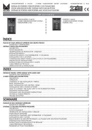
AUDIO UNITMIXED AUDIO UNIT GRF-005GroundTerminal connectionsMake the connections to the terminals as indicatedin the diagram.GRF-005cod. 9610212 V~V~ 9 10 11 121 2 3 4Made in Spain7 8V123478Power supply voltageDoor lock releaseTelephone common terminalTelephone microphoneTelephone loudspeakerCommon push button terminal (electronic call)Common push button terminal (buzzer call)9Panel lighting10Panel lighting11Electric lock12 Electric lockFor electronic calls, connect the push buttoncommon terminal 7, to the push buttons on the<strong>entrance</strong> <strong>panel</strong>.V~ 9 10 11 12 1 2 3 4 7 8For a buzzer, connect the push button commonterminal 8, to the push buttons on the <strong>entrance</strong><strong>panel</strong>.V~ 9 10 11 12 1 2 3 4 788Connect the <strong>entrance</strong> <strong>panel</strong> lighting bulbs to terminals9 and 10.V~ 9 10 11 12 1 2 3 4 7 8Audio unit set-upIf you want a tri-tone call, remove jumper J2.J2V~ 9 10 11 12 1 2 3 4 7 8If necessary regulate the volume levels of the<strong>entrance</strong> <strong>panel</strong> and the telephones using the volumecontrol potentiometers on the audio unit.32
AUDIO UNIT MULTI ENTRANCE WITHOUTPRIVACY OF CONVERSATION GRF-003AUDIO UNIT WITH PRIVACY OFCONVERSATION GRF-004Terminal connectionsMake the connections to the terminals as indicatedin the diagram.GRF-003cod. 96104GRF-004Made in Spaincod. 9610519 20J112 V~V~ 9 10 11 12 13 14 15 1 2 3 4 7 16 17 18GroundV Power supply voltage1 Door lock release2 Telephone common terminal3 Telephone microphone4 Telephone loudspeaker7 Common push button terminal (electronic call)9 Panel lighting10 Panel lighting11 Electronic lock12 Electronic lock16 Multiple acces complex17 Multiple access18 Principal access common terminalConnect the push button common terminal 7, tothe push buttons on the <strong>entrance</strong> <strong>panel</strong>.V~ 9 10 11 12 1 2 3 4 716 1718Connect the <strong>entrance</strong> <strong>panel</strong> lighting bulbs to terminals9 and 10.V~ 9 10 11 12 1 2 3 4 7 16 1718Audio unit set-upThe <strong>entrance</strong> <strong>panel</strong> defined as being the system’smain <strong>panel</strong> must have jumper J1 in place.Only one main <strong>panel</strong> can be defined per installation.Therefore, remove jumper J1 from the audiounits of the rest of the <strong>panel</strong>s in the system.J1V~ 9 10 11 12 13 14 15 1 2 3 4 7 16 17 18If necessary regulate the volume level of the<strong>entrance</strong> <strong>panel</strong> and the telephones using the volumecontrol potentiometers on the audio unit.33
TELEPHONEELECTRONIC TELEPHONE TEL-001ELECTRONIC TELEPHONE WITH PRIVACYOF CONVERSATION TES-001Terminal connectionsMake the connections to the terminals as indicatedin the diagram.CallDoor lock releaseCommonTelephone microphoneTelephone microphoneElectronic callAudio unitPush buttonUNIVERSAL TELEPHONE TUN-001Terminal connectionsMake the connections to the terminals as indicatedin the diagram.J1Door lock releaseCommonTelephone microphoneTelephone microphoneElectronic callBuzzer callCallAudio UnitPush buttonTelephone set-upFit jumper J1 in position B if your door entrysystem is of the separated common lines type.ABPossible positions ofJ1 jumperIf necessary, regulate the telephone microphoneand loud speaker volume level to avoid feedbackwith the <strong>entrance</strong> <strong>panel</strong> or the telephone itself. Toregulate the volume level use the potentiometerson the telephone base.34
POWER SUPPLYTerminal connectionsThe power supply must be connected on oneside to the electrical mains and on the other to the<strong>entrance</strong> <strong>panel</strong> audio unit. Make the connectionsas shown in the diagram.230 V Mains voltageGround (to the audio unit)V Output voltage (to the audio unit)35
6CIRCUIT DIAGRAMSGENERAL POINTS CONCERNING THE INSTALLATIONWire cross-sectionsWhen wiring the installation observe the cross-section specifications given below. This will ensure the correctfunctioning of the door entry system.Up to 150 mCommon and call cablesTelephonePower and electric lock cablesUp to 300 mTelephoneUp to 600 mTelephoneCommon and call cablesPower and electric lock cablesCommon and call cablesPower and electric lock cables0.25 mm 20.5 mm 20.5 mm 21 mm 21 mm 22 mm 2If several telephones connected to the same call line are fitted in the dwelling it may be necessary toincrease the wire cross-section in order to maintain sound quality. If so, increase the call wire cross-section inproportion to the number of telephones as follows.x 2x 3x 4Remember to protect the power supplies (breaker, etc) in order to comply with nationalsafety standards.37
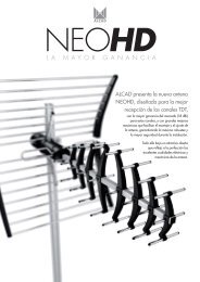
4+N SYSTEM CIRCUIT DIAGRAMSBASIC INSTALLATION WITH ELECTRONIC CALL4+N SYSTEMBasic circuit diagram of door entry system installationin buildings with a single <strong>entrance</strong>.OperationWhen one of the push buttons on the <strong>entrance</strong><strong>panel</strong> is pressed the electronic call signal generatedby the audio unit (7) is sent via the call line to thecorresponding telephone (5), where it is heard onthe loudspeaker of the handset. At the same time theaudio unit’s own loudspeaker generates a sound toconfirm to the visitor that the call has been made.When the handset is picked up the electronicsassociated to the telephone’s audio lines (3 and 4) isinternally connected to the <strong>entrance</strong> <strong>panel</strong>. This connectionsets up the communication between the telephoneand the <strong>entrance</strong> <strong>panel</strong>.When the door lock release opener button on thetelephone is pressed, the audio unit detects the closingof the lock release circuit (1). The audio unit thensends an a/c voltage (11 and 12) to the electriclock, thus allowing the <strong>entrance</strong> door to be opened.The common wire (2) of the telephone and <strong>entrance</strong><strong>panel</strong> provides the return path for all the telephonesignals.55230 VVALA-04022TEL-0015 54+NMAN-010MPD-004ABR-00138MATERIAL REQUIREDMPS-/MPDPush button <strong>panel</strong>module (dependingon characteristics ofthe installation)9670001 MAN - 010 Entrance <strong>panel</strong>module with electronic audio unit 4+Nsystem9600001 TEL - 001 Electronic telephones9620001 ALA - 040 Power supply9730000 ABR - 001 Electric lock (othermodels available)CMO Flush-mounted box(depending on characteristicsof theinstallation)
BASIC INSTALLATION WITH ELECTRONIC CALL4+N SYSTEMTABLE OF CROSS SECTIONSUp to 150 meters0,5 mm20,8 mmAWG201 2 3 4 51 2 3 4 50,25 mm20,6 mm22TEL-001CallCall1 2 3 4 51 2 3 4 5ALA-040CallCall230 VVJ2230 V V~9 10 11 121 2 3 4 7MAN-010MPD-004ABR-001Calls39
BASIC INSTALLATION WITH BUZZER CALL4+N SYSTEMBasic circuit diagram of door entry system installationin buildings with a single <strong>entrance</strong>.55OperationWhen one of the push buttons on the <strong>entrance</strong><strong>panel</strong> is pressed the call signal generated by theaudio unit (8) is sent via the call line to the correspondingtelephone (6) where it is heard. At the sametime the audio unit’s own loudspeaker generates asound to confirm to the visitor that the call has beenmade.When the handset is picked up the electronicsassociated to the telephone’s audio lines (3 and 4) isinternally connected to the <strong>entrance</strong> <strong>panel</strong>. This connectionsets up the communication between the telephoneand the <strong>entrance</strong> <strong>panel</strong>.When the door lock release button on the telephoneis pressed, the audio unit detects the closing of thelock release circuit (1). The audio unit then sends ana/c voltage (11 and 12) to the electric lock, thus allowingthe <strong>entrance</strong> door to be opened.The common wire (2) of the telephone and <strong>entrance</strong><strong>panel</strong> provides the return path for all the telephonesignals.230VVALA-040ABR-001225 54+NTUN-001MAN-050MPD-004MATERIAL REQUIREDMPS-/MPD Push button <strong>panel</strong>module (dependingon characteristicsof the installation)9670002 MAN - 050 Entrance <strong>panel</strong> withmixed audio unit4+N system9600002 TUN - 001 Universal telephones(electronic/buzzer)9620001 ALA - 040 Power supply9730000 ABR - 001 Electric lock (othermodels available)CMO Flush-mounted boxcoepending oncharacteristics ofthe installation)40
BASIC INSTALLATION WITH BUZZER CALL4+N SYSTEMTABLE CROSS SECTIONSJ1J1Up to 150 metersAWG0,5 mm20,8 mm201 2 3 4 561 2 3 4 560,25 mm20,6 mm22TUN-001CallCallJ1J11 2 3 4 561 2 3 4 56CallCallALA-040230 VVJ2230 V V~9 10 11 121 2 3 4 7 8MAN-050MPD-004ABR-001Calls41
EXPANSION OF THE INSTALLATION WITH ADDITIONALTELEPHONES4+N SYSTEMUseIt is possible to expand a one dwelling system byadding telephones (maximum 4 telephones persystem). Each telephone will have the same featuresas the original telephone: call reception, communicationwith the <strong>entrance</strong> <strong>panel</strong> and opening the<strong>entrance</strong> door.in the system. If the cross-sections indicated in thismanual are observed, it is possible to install up to 4telephones and still obtain a reasonable call volume.Material required9600001 TEL-001 Electronic telephonesOperationThe electronic call signal is common to all the telephones.As the call signal is shared between all thetelephones the volume level drops. The call volumealso depends on the cross-sections of the wires used1 2 3 4 51 2 3 4 51 2 3 4 5TEL-00142
OPENING THE DOOR FROM INSIDE THE BUILDING4+N SYSTEMUseWhen the <strong>entrance</strong> door does not have ahandle on the inside push button should be installedto activate the lock release. While the electriclock is activated it is possible to open the door.OperationWhen the door lock release is pressed, theaudio unit detects the closing of the lock releasecircuit (1). The audio unit then sends an a/c voltage(11 and 12) to the electric lock allowing the<strong>entrance</strong> door to be opened.The push button is preferable to be fitted near tothe <strong>entrance</strong> door so that it can be opened whilethe push button is pressed. If this is not possible,an ABR-003 (ref. 9730002) automatic electriclock which remains released until the door is openedcould be fitted.Material requiredOnly a push button is required.Basic circuit diagram of door entry system installa-TABLE CROSS SECTIONSUp to150 metersAWG0,5 mm20,8 mm200,25 mm20,6 mm22J2V~9 10 11 121 2 3 4 7Opening push buttonMAN-010 (Electronic call)MAN-050 (Buzzer call)MPD-004ABR-00143
MICROPROCESSOR-BASED 4+N SYSTEM CIRCUIT DIAGRAMSBASIC INSTALLATION WITH ELECTRONIC CALLMICROPROCESSOR-BASED 4+N SYSTEMtion in buildings with a single <strong>entrance</strong>.55OperationWhen one of the push buttons on the <strong>entrance</strong><strong>panel</strong> is pressed the electronic call signal generatedby the audio unit (7) is sent via the call line to thecorresponding telephone (5), where it is heard onthe loudspeaker of the handset. At the same time theaudio unit’s own loudspeaker generates a sound toconfirm to the visitor that the call has been made.5 5When the handset is picked up the electronicsassociated to the telephone’s audio lines (3 and 4) isinternally connected to the <strong>entrance</strong> <strong>panel</strong>. This connectionsets up the communication between the telephoneand the <strong>entrance</strong> <strong>panel</strong>.When the door lock release button on the telephoneis pressed, the audio unit detects the closing of thelock release circuit (1). The audio unit then sends ana/c voltage (11 and 12) to the electric lock, thus allowingthe <strong>entrance</strong> door to be opened.The common wire (2) of the telephone and <strong>entrance</strong><strong>panel</strong> provides the return path for all the telephonesignals.230 VVALA-04022TEL-0014+NMAN-030MPD-004Basic circuit diagram of door entry system installationABR-00144MATERIAL REQUIREDMPS-/MPDPush button <strong>panel</strong>module (dependingon characteristics ofthe installation)9670004 MAN - 030 Entrance <strong>panel</strong>with audio unit multi<strong>entrance</strong> withoutprivacy ofconversation, 4+Nsystem9600001 TEL - 001 Electronic telephones9620001 ALA - 040 Power supply9730000 ABR - 001 Electric lock (othermodels available)CMO Flush-mounted box(depending oncharacteristics ofthe installations)
BASIC INSTALLATION WITH ELECTRONIC CALLMICROPROCESSOR-BASED 4+N SYSTEMTABLE CROSS SECTIONSUp to 150 meters0,5 mm20,8 mmAWG201 2 3 4 51 2 3 4 50,25 mm20,6 mm22TEL-001CallCall1 2 3 4 51 2 3 4 5ALA-040CallCall230 VV19 20J1230 V V~ 9 1 2 3 4 710 11 12 13 14 15 16 17 18MAN-030MPD-004ABR-001Calls45
BASIC INSTALLATION WITH ELECTRONIC CALL AND PRIVACY OFCONVERSATIONMICROPROCESSOR-BASED 4+N SYSTEMwith speech privacy, for use in buildings with a single<strong>entrance</strong>.Telephones with the privacy of conversation featureremain inactive until they are called from the <strong>entrance</strong><strong>panel</strong>. Until a call is received the dwelling telephone isdisabled so that it is not possible to listen to conversationsbetween other telephones and the <strong>entrance</strong> <strong>panel</strong>.555 5OperationWhen one of the push buttons on the <strong>entrance</strong> <strong>panel</strong>is pressed the electronic call signal generated by theaudio unit (7) is sent via the call line to the correspondingtelephone (5), where it is heard on the loudspeakerof the handset. At the same time the audio unit’sown loudspeaker generates a sound to confirm to thevisitor that the call has been made.The telephone receiving the call is activated by connectingits electronics internally to the common wire (2)and the door lock release wire (1). While the telephoneis activated on it is possible to open the door or communicatewith the caller by picking up the handset.Once the call is received, the audio unit starts a 30second timer while it waits for the telephone handset tobe picked up. If the handset is not picked up during thistime the audio unit disables the telephone.Once the call is received the handset is picked up theelectronics associated to the telephone’s audio lines (3and 4) is internally connected to the <strong>entrance</strong> <strong>panel</strong>.This connection sets up the communication between thetelephone and the <strong>entrance</strong> <strong>panel</strong>. The audio unit thenstarts a fresh 60 second conversation period beforedisabling the telephone. When only 10 seconds are lefta buzz will be heard. It is possible to restart the timereither from the <strong>entrance</strong> <strong>panel</strong>, by pressing the call button,or from the dwelling end, by pressing and releasingthe telephone handset’s hook switch.When the door lock release button on the telephoneis pressed, the audio unit detects the closing of the lockrelease circuit (1). The audio unit then sends an a/c voltage(11 and 12) to the electric lock, thus allowing the<strong>entrance</strong> door to be opened.The common wire (2) of the telephone and <strong>entrance</strong> <strong>panel</strong>provides the return path for all the telephone signals. The commonwire is connected while the telephone is active.46230 VVALA-040ABR-001MATERIAL REQUIRED22TES-001MAN-040MPD-0044+NMPS-/MPD Push button <strong>panel</strong>module (dependingon characteristics ofthe installation)9670005 MAN - 040 Entrance <strong>panel</strong>module with audiounit with privacyof conversation,4+N system9600003 TES - 001 Electronic telephoneswith privacy ofconversation9620001 ALA - 040 Power supply9730000 ABR - 001 Electric lock (othermodels available)CMO Flush-mounted box(depending oncharacteristicsof installation)
BASIC INSTALLATION WITH ELECTRONIC CALL AND PRIVACY OFCONVERSATIONMICROPROCESSOR-BASED 4+N SYSTEMTABLE CROSS SECTIONUp to 150 metersAWG0,5 mm20,8 mm201 2 3 4 51 2 3 4 50,25 mm20,6 mm22TES-001CallCall1 2 3 4 51 2 3 4 5ALA-040CallCall230 VV19 20J1230 V V~ 9 10 11 12 13 14 15 1 2 3 4 7 16 17 18MAN-040MPD-004ABR-001Calls47
TWO ENTRANCE INSTALLATION WITH ELECTRONIC CALLMICROPROCESSOR-BASED 4+N SYSTEMBasic circuit diagram of door entry system installationin buildings with two <strong>entrance</strong>s.<strong>Alcad</strong> multiple <strong>entrance</strong> systems are based onthe use of microprocessor-controlled audio units(microprocessor-based 4+N system). Rather thanusing changeover switches to select one of the<strong>entrance</strong> <strong>panel</strong>s, the audio unit has been fittedwith a microprocessor that decides which <strong>entrance</strong><strong>panel</strong> should be activated, and deactivates therest of the <strong>panel</strong>s in the system.This system simplifies the cabling of the installation,reduces the number of components andimproves system operation.OperationOne of the <strong>entrance</strong> <strong>panel</strong>s in the system is chosento be the main <strong>panel</strong> just one <strong>panel</strong> per installationcan be defined as the main one. To select it, removejumper J1 from the other <strong>entrance</strong> <strong>panel</strong>. The main<strong>panel</strong> is the one which is connected by default to thesystem’s telephones. The other <strong>panel</strong> is only activatedwhen one of the call buttons is pressed.When a call button is pressed, the corresponding<strong>panel</strong> comes on to allow communication with thetelephones. The system busy indicator light on theother <strong>panel</strong> will start to flash to indicate that it is disabled.When a push button on one of the <strong>entrance</strong> <strong>panel</strong>sis pressed the electronic call signal generated by theaudio unit (7) is sent via the call line to the correspondingtelephone (5), where it is heard on theloudspeaker of the handset. At the same time theaudio unit’s own loudspeaker generates a sound toconfirm to the visitor that the call has been made. Theaudio unit also generates a control signal (17) thatdisables the other <strong>entrance</strong> <strong>panel</strong>.The audio unit starts a 30 second timer while itwaits for the telephone handset to be picked up. Ifthe handset is not picked up during this time, the controlsignal (17) is removed and both <strong>panel</strong>s go intothe standby state.If the handset is picked up during this time, theelectronics associated to the telephone’s audio lines(3 and 4) is internally connected to the <strong>entrance</strong><strong>panel</strong>. This connection sets up the communicationbetween the telephone and the <strong>entrance</strong> <strong>panel</strong>. Theaudio unit starts a fresh 60 second period beforeremoving the control signal (17) and putting both<strong>panel</strong>s into standby state. When only 10 secondsare left a buzz will be heard. It is possible to restartthe timer from the dwelling end by pressing and releasingthe telephone handset’s hook switch. After finishingthe communication, when the audio unitdetects that the telephone handset has been hung up,it removes the control signal (17) and both <strong>panel</strong>s gointo the standby state.When the door lock release button on the telephoneis pressed, the audio unit of the active <strong>panel</strong>detects the closing of the lock release circuit (1). Theaudio unit then sends an a/c voltage (11 and 12) tothe electric lock connected to the active <strong>entrance</strong><strong>panel</strong>, thus allowing the <strong>entrance</strong> door to be opened.The common wire (2) of the telephone and <strong>entrance</strong><strong>panel</strong> provides the return path for all the telephonesignals.48
VTWO ENTRANCE INSTALLATION WITH ELECTRONIC CALLMICROPROCESSOR-BASED 4+N SYSTEM555 5TEL-001ALA-040230VV4+N230VVALA-04022MAN-0306+N2 2MPD-004MAN-030MPD-004ABR-001ABR-001MATERIAL REQUIREDMPS -/MPD Push button <strong>panel</strong>module (dependingon characteristics ofthe installation)9670004 MAN - 030 Entrance <strong>panel</strong>module with audiounit multi <strong>entrance</strong>without privacy ofconversation,4+N system9600001 TEL - 001 Electronic telephones9620001 ALA - 040 Power supply9730000 ABR - 001 Electric lock (othermodels available)CMO Flush mounted box(depending on characteristicsof the installation)49
TWO ENTRANCE INSTALLATION WITH ELECTRONIC CALLMICROPROCESSOR-BASED 4+N SYSTEMTABLE CROSS SECTIONSUp to 150 meters2 0,5 mm 0,8 mm2 0,25 mm 0,6 mmAWG20221 2 3 4 5 1 2 3 4 5TEL-001CallCall1 2 3 4 51 2 3 4 5CallCall230 VV19 20J1230 VV19 20J1230 VALA-040ALA-040V~ 9 10 11 12 13 14 15 1 2 3 4 7 16 17 18V~ 9 10 11 12 13 14 15 1 2 3 4 7 16 17 18230 VMAN-030MAN-030ABR-001MPD-004CallABR-001MPD-004Call50
THREE ENTRANCE INSTALLATION WITH ELECTRONIC CALLMICROPROCESSOR-BASED 4+N SYSTEMBasic circuit diagram of door entry system installationin buildings with three <strong>entrance</strong>s. <strong>Alcad</strong> multiple<strong>entrance</strong> systems are based on the use ofmicroprocessor-controlled audio units (microprocessor-based4+N system). Rather than using changeoverswitches to select one of the <strong>entrance</strong> <strong>panel</strong>s,the audio unit has been fitted with a microprocessorthat decides which <strong>entrance</strong> <strong>panel</strong> should be activated,and deactivates the rest of the <strong>panel</strong>s in thesystem.This system simplifies the cabling of the installation,reduces the number of components and improvessystem operation.OperationOne of the <strong>entrance</strong> <strong>panel</strong>s in the system is chosento be the main <strong>panel</strong> just one <strong>panel</strong> per installationcan be defined as the main one. To selectit, remove jumper J1 from the other <strong>entrance</strong><strong>panel</strong>. The main <strong>panel</strong> is the one which is connectedby default to the system’s telephones. Theother <strong>panel</strong>s are only activated when one of thecall buttons is pressed.When a call button is pressed, the corresponding<strong>panel</strong> is activated to allow communicationwith the telephones. The system busy indicator onthe other <strong>panel</strong>s will start to flash to indicate thatthey are disabled.When a push button on one of the <strong>entrance</strong><strong>panel</strong>s is pressed, the electronic call signal generatedby the audio unit (7) is sent via the call lineto the corresponding telephone (5), where it isheard on the loudspeaker of the handset. At thesame time the audio unit’s own loudspeaker generatesa sound to confirm to the visitor that the callhas been made. The audio unit also generates acontrol signal (17) that disables the other <strong>entrance</strong><strong>panel</strong>s.The audio unit starts a 30 second timer while itwaits for the telephone handset to be picked up. Ifthe handset is not picked up during this time, thecontrol signal (17) is removed and all three <strong>panel</strong>sgo into the standby state.If the handset is picked up during this time, theelectronics associated to the telephone’s audiolines (3 and 4) is internally connected to the<strong>entrance</strong> <strong>panel</strong>. This connection sets up the communicationbetween the telephone and the <strong>entrance</strong><strong>panel</strong>. The audio unit starts a fresh 60 secondperiod before removing the control signal (17)and putting all three <strong>panel</strong>s into standby state.When only 10 seconds are left a buzz will beheard. It is possible to restart the timer from thedwelling end by pressing and releasing the telephonehook switch. After finishing the communication,when the audio unit detects that the telephonehandset has been hung up, it removes thecontrol signal (17) and all three <strong>panel</strong>s go into thestandby state.When the door lock release button on the telephoneis pressed, the active audio unit detects theclosing of the lock release circut (1). The audiounit then sends an a/c voltage (11 and 12) to theelectric lock connected to the active <strong>entrance</strong><strong>panel</strong>, thus allowing the <strong>entrance</strong> door to be opened.The common wire (2) of the telephone and<strong>entrance</strong> <strong>panel</strong> provides the return path for all thetelephone signals.51
THREE ENTRANCE INSTALLATION WITH ELECTRONIC CALLMICROPROCESSOR-BASED 4+N SYSTEM555 54+NTEL-001ALA-040ALA-040ALA-040230 VV230 VV230 VV222MAN-0306+NMAN-0306+NMAN-0302MPD-0042MPD-0042MPD-004ABR-001ABR-001ABR-00152MATERIAL REQUIREDMPS-/MPD Push button <strong>panel</strong>module (dependingon characteristics ofthe installation)9670004 MAN - 030 Entrance <strong>panel</strong>module with audiounit multi <strong>entrance</strong>(without privacy ofconversation),4+N system9600001 TEL - 001 Electronic telephones9620001 ALA - 040 Power supply9730000 ABR - 001 Door opener (othermodels available)CMO Flush-mounted box(depending oncharacteristics of theinstallation
THREE ENTRANCE INSTALLATION WITH ELECTRONIC CALLMICROPROCESSOR-BASED 4+N SYSTEMTABLE CROSS SECTIONSUp to150 metersAWG0,5 mm20,8 mm201 2 3 4 51 2 3 4 50,25 mm20,6 mm22TEL-001CallCall1 2 3 4 51 2 3 4 5CallCall230 V V230 VV230 VV230 VALA-040230 VALA-040230 VALA-04019 2019 2019 20J1J1J19 1 2 3 4 710 11 12 13 14 15 16 17 189 1 2 3 4 710 11 12 13 14 15 16 17 18V V V9 10 11 12 13 14 15 1 2 3 4 7 16 17 18ABR-001ABR-001ABR-001CallCallCallMAN-030MAN-030MAN-030MPD-004MPD-004MPD-00453
INSTALLATION WITH ELECTRONIC CALL IN A COMPLEXWITH SEVERAL BLOCKSMICROPROCESSOR-BASED 4+N SYSTEMBasic circuit diagram of a door entry system installationin a complex with several blocks.<strong>Alcad</strong> multiple <strong>entrance</strong> systems are based on theuse of microprocessor-controlled audio units (microprocessor-based4+N system). Rather than usingchangeover switches to select one of the <strong>entrance</strong><strong>panel</strong>s, the audio unit has been fitted with a microprocessorthat decides which <strong>entrance</strong> <strong>panel</strong> shouldbe activated, and deactivates the rest of the <strong>panel</strong>s inthe system.This system simplifies the cabling of the installation,reduces the number of components and improvessystem operation.This type of installation can be treated as several installationswith two <strong>entrance</strong>s each joined together. Onthe main <strong>entrance</strong> to the complex or residential thereare as many <strong>entrance</strong> <strong>panel</strong>s as buildings inside thecomplex. Thus, each <strong>entrance</strong> <strong>panel</strong> at the main<strong>entrance</strong> is associated dust with the <strong>entrance</strong> <strong>panel</strong> ofone of the buildings. Each pair of <strong>panel</strong>s works in thesame way as a two-<strong>entrance</strong> installation.OperationEach <strong>entrance</strong> <strong>panel</strong> at the main <strong>entrance</strong> end isselected as the main <strong>panel</strong> of the system. Just one<strong>panel</strong> per installation can be defined as the main one.To select it, remove jumper J1 from the buildings<strong>entrance</strong> <strong>panel</strong>s. The main <strong>panel</strong> is the one which isconnected by default to the system’s telephones. Theother <strong>panel</strong>s are only activated when one of the callbuttons is pressed.When a call button is pressed, the corresponding<strong>panel</strong> is activated to allow communication with thetelephones. The system busy indicator light on theassociated <strong>panel</strong> will start to flash to indicate that it isdisabled. If the call is made from an <strong>entrance</strong> <strong>panel</strong>from the main <strong>entrance</strong> to the residential, it´s possibleto disable not only the building associated to that<strong>panel</strong> but also the rest of the <strong>panel</strong>s of the main <strong>entrance</strong>.To do so the various <strong>panel</strong>s need to be interconnectedvia terminal 16.When one of the push buttons on one of the <strong>entrance</strong><strong>panel</strong>s is pressed the electronic call signal generatedby the audio unit (7) is sent via the call line to thecorresponding telephone (5), where it is heard on theloudspeaker of the handset. At the same time theaudio unit’s own loudspeaker generates a sound toconfirm to the visitor that the call has been made. Theaudio unit also generates a control signal (17) thatdeactivates the associated <strong>entrance</strong> <strong>panel</strong>. When thevisitor is calling from the main <strong>entrance</strong>, the audio unitgenerates a control signal (16) which disables the restof the <strong>panel</strong>s at the <strong>entrance</strong>.The audio unit starts a 30 second timer while it waitsfor the telephone handset to be picked up. If the handsetis not picked up during this time, the control signal(17) and (16) (in the case of the main <strong>entrance</strong>) isremoved and the <strong>panel</strong>s go into the standby state.If the handset is picked up during this time, the electronicsassociated to the telephone’s audio lines (3and 4) is internally connected to the <strong>entrance</strong> <strong>panel</strong>.This connection sets up the communication betweenthe telephone and the <strong>entrance</strong> <strong>panel</strong>. The audio unitstarts a fresh 60 second period before removing thecontrol signals (17) and (16) (in the case of the main<strong>entrance</strong>) and putting the <strong>panel</strong>s into standby state.When only 10 seconds are left a buzz will be heard.It is possible to restart the timer from the dwelling endby pressing and releasing the telephone handset’shook switch. After finishing the communication, whenthe audio unit detects that the telephone handset hasbeen hung up, it removes the control signals (17) and(16) (in the case of the main <strong>entrance</strong>) and the <strong>panel</strong>sgo into the standby state.When the door lock release button on the telephoneis pressed, the active audio unit detects the closingof the lock release circuit (1). The audio unit thensends an a/c voltage (11 and 12) to the electric lockconnected to the active <strong>entrance</strong> <strong>panel</strong>, thus allowingthe <strong>entrance</strong> door to be opened.The common wire (2) of the telephone and <strong>entrance</strong><strong>panel</strong> provides the return path for all the telephonesignals.54
INSTALLATION WITH ELECTRONIC CALL IN A COMPLEXWITH SEVERAL BLOCKSMICROPROCESSOR-BASED 4+N SYSTEM5555555 55 55 5TEL-0014+NTEL-0014+NTEL-0014+NALA-040ALA-040ALA-040MAN-030230 V V230 V VMAN-030230 VVMAN-03022MPD-00422MPD-00422MPD-004BUILDING A BUILDING B BUILDING C6+N 6+N6+NABR-001ABR-001ABR-001ALA-040MATERIAL REQUIREDMPS-/MPD Push button <strong>panel</strong>module (dependingon characteristics ofthe installation)9670004 MAN - 030 Entrance <strong>panel</strong>module with audiounit multi <strong>entrance</strong>(without privacy ofconversation),4+N system9600001 TEL - 001 Electronic telephones9620001 ALA - 040 Power supply9730000 ABR - 001 Electric lock (othermodels available)ABR - 001 Flush-mounted box(depending oncharacteristicsof the installation)9740004 CEM - 001 Flush-mounted boxset of separators230 VVABR-00122MAN-030 X 3MPD-004 X 355
9 10 11 12 13 14 15 1 2 3 4 7 16 17 18INSTALLATION WITH ELECTRONIC CALL IN A COMPLEXWITH SEVERAL BLOCKSMICROPROCESSOR-BASED 4+N SYSTEMTABLE CROSS SECTIONSUp to150 meters2 0,5 mm 0,8 mm2 0,25 mm 0,6 mmAWG20221 2 3 4 5TEL-001TEL-001ALA-040TEL-001Call19 20J1ALA-040MAN-030ALA-040MAN-030230 VVV230 V230 VV230 VVMAN-030MPD-004BUILDING AMPD-004BUILDING BABR-001MPD-004BUILDING CCallBUILDING CABR-001ABR-001ALA-04019 20J119 20J119 20J1230 VV9 1 2 3 4 710 11 12 13 14 15 16 17 189 1 2 3 4 7V V V10 11 12 13 14 15 16 17 18 9 1 2 3 4 710 11 12 13 14 15 16 17 18230 VMAN-030 X 3MPD-004 X 3ABR-001COMMON ACCESSCallBUILDING ACallBUILDING BCallBUILDING C56
TWO ENTRANCE INSTALLATION WITH ELECTRONIC CALLAND PRIVACY OF CONVERSATIONMICROPROCESSOR-BASED 4+N SYSTEMBasic circuit diagram of door entry system installationwith speech privacy, for use in buildings withtwo <strong>entrance</strong>s.<strong>Alcad</strong> multiple <strong>entrance</strong> systems are based on theuse of microprocessor-controlled audio units (microprocessor-based4+N system). Rather than usingchangeover switches to select one of the <strong>entrance</strong><strong>panel</strong>s, the audio unit has been fitted with a microprocessorthat decides which <strong>entrance</strong> <strong>panel</strong> shouldbe activated, and disables the rest of the <strong>panel</strong>s inthe system.This system simplifies the cabling of the installation,reduces the number of components and improvessystem operation.Telephones with the privacy of conversation featureremain inactive until they are called from the<strong>entrance</strong> <strong>panel</strong>. Until a call is received the dwellingtelephone is disabled so that it is not possible to listento conversations between other tele-phones andthe <strong>entrance</strong> <strong>panel</strong>.OperationOne of the <strong>entrance</strong> <strong>panel</strong>s in the system is chosento be the main <strong>panel</strong> just one <strong>panel</strong> per installationcan be defined as the main one. To select it, removejumper J1 from the other <strong>entrance</strong> <strong>panel</strong>. The main<strong>panel</strong> is the one which is connected by default to thesystem’s telephones. The other <strong>panel</strong> is only activatedwhen one of the call buttons is pressed.When a call button is pressed, the corresponding<strong>panel</strong> is activated to allow communication with thetelephones. The system busy indicator light on other<strong>panel</strong> will start to flash to indicate that it is disabled.When one of the push buttons on one of the<strong>entrance</strong> <strong>panel</strong>s is pressed the electronic call signalgenerated by the audio unit (7) is sent via the callline to the corresponding telephone (5), where it isheard on the loudspeaker of the handset. At thesame time the audio unit’s own loudspeaker generatesa sound to confirm to the visitor that the call hasbeen made. The audio unit also generates a controlsignal (17) that disables the other <strong>entrance</strong> <strong>panel</strong>.The telephone that receives the call is activated byconnecting its electronics internally to the commonwire (2) and the door lock wire (1). While the telephoneis activated on it is possible to open the dooror communicate with the caller by picking up thehandset. Once the call is received, the audio unitstarts a 30 second timer while it waits for the telephonehandset to be picked up. If the handset is notpicked up during this time, the control signal (17) isremoved and both <strong>panel</strong>s go into the standby state.If the handset is picked up during this time, theelectronics associated the telephone’s audio lines (3and 4) is internally connected to the <strong>entrance</strong> <strong>panel</strong>.This connection sets up the communication betweenthe telephone and the <strong>entrance</strong> <strong>panel</strong>. The audiounit starts a fresh 60 second period before disablingthe telephone and removing the control signal (17),putting both <strong>panel</strong>s into standby state. When only10 seconds are left a buzz will be heard. It is possibleto restart the timer either from the <strong>entrance</strong><strong>panel</strong>, by pressing the push button, or from the dwellingend, by pressing and releasing the telephonehandset’s hook switch. After finishing the communication,when the audio unit detects that the telephonehandset has been hung up, it removes the controlsignal (17) and both <strong>panel</strong>s go into the standbystate.When the door lock release button on the telephoneis pressed, the audio unit detects the closingof the lock release circuit (1). The audio unit thensends an a/c voltage (11 and 12) to the electric lockconnected to the active <strong>entrance</strong> <strong>panel</strong>, thus allowingthe <strong>entrance</strong> door to be opened.The common wire (2) of the telephone and <strong>entrance</strong><strong>panel</strong> provides the return path for all the telephonesignals. The common wire is connected while thetelephone is active.57
TWO ENTRANCE INSTALLATION WITH ELECTRONIC CALLAND PRIVACY OF CONVERSATIONMICROPROCESSOR-BASED 4+N SYSTEM555 5TES-001230 VV4+N230 VVALA-0402ALA-0402MAN-0406+N2 2MPD-004MAN-040MPD-004MATERIAL REQUIRED58ABR-001ABR-001MPS - /MPD Push button <strong>panel</strong>module(dependingon characteristics ofthe installation)9670005 MAN - 040 Entrance <strong>panel</strong>with audio unit(with privacyof conversation),4+N system9600003 TES - 001 Electronic telephoneswith privacy ofconversation9620001 ALA - 040 Power supply9730000 ABR - 001 Electric lock (othermodels available)CMO Flush-mounted box(dependingon characteristicsof the installation)
TWO ENTRANCE INSTALLATION WITH ELECTRONIC CALLAND PRIVACY OF CONVERSATIONMICROPROCESSOR-BASED 4+N SYSTEMTABLE CROSS SECTIONSUp to 150 meters2 0,5 mm 0,8 mm2 0,25 mm 0,6 mmAWG20221 2 3 4 5 1 2 3 4 5TES-001CallCall1 2 3 4 51 2 3 4 5CallCall230 VV19 20J1230 VV19 20J1230 VALA-040ALA-040V~ 9 10 11 12 13 14 15 1 2 3 4 7 16 17 18V~ 9 10 11 12 13 14 15 1 2 3 4 7 16 17 18230 VMAN-040MAN-040ABR-001MPD-004CallABR-001MPD-00459
THREE ENTRANCE INSTALLATION WITH ELECTRONIC CALLAND PRIVACY OF CONVERSATIONMICROPROCESSOR-BASED 4+N SYSTEMBasic circuit diagram of door entry system installationwith speech privacy, for use in buildings withthree <strong>entrance</strong>s.<strong>Alcad</strong> multiple <strong>entrance</strong> systems are based on theuse of microprocessor-controlled audio units (microprocessor-based4+N system). Rather than usingchangeover switches to select one of the <strong>entrance</strong><strong>panel</strong>s, the audio unit has been fitted with a microprocessorthat decides which <strong>entrance</strong> <strong>panel</strong> shouldbe activated, and deactivates the rest of the <strong>panel</strong>sin the system.This system simplifies the cabling of the installation,reduces the number of components and improvessystem operation.Telephones with the privacy of conversation featureremain inactive until they are called from the<strong>entrance</strong> <strong>panel</strong>. Until a call is received the dwellingtelephone is disabled. It is therefore not possible tolisten to conversations between other tele-phones andthe <strong>entrance</strong> <strong>panel</strong>.OperationOne of the <strong>entrance</strong> <strong>panel</strong>s in the system is chosento be the main <strong>panel</strong> just one <strong>panel</strong> per installationcan be defined as the main one. To select it, removejumper J1 from the other <strong>entrance</strong> <strong>panel</strong>s. The main<strong>panel</strong> is the one which is connected by default to thesystem’s telephones. The other <strong>panel</strong>s are only activatedwhen one of the call buttons is pressed.When a call button is pressed, the corresponding<strong>panel</strong> comes on to allow communication with thetelephones. The system busy indicator light on theother <strong>panel</strong>s will start to flash to indicate that they aredisabled.When one of the push buttons on one of the<strong>entrance</strong> <strong>panel</strong>s is pressed the electronic call signalgenerated by the audio unit (7) is sent via the call lineto the corresponding telephone (5), where it is heardon the loudspeaker of the handset. At the same timethe audio unit’s own loudspeaker generates a soundto confirm to the visitor that the call has been made.The audio unit also generates a control signal (17)that deactivates the other <strong>entrance</strong> <strong>panel</strong>s.The telephone that receives the call is activated byconnecting its electronics internally to the commonwire (2) and the door lock release wire (1). Whilethe telephone is activated it is possible to open thedoor or communicate with the caller by picking upthe handset. Once the call is received, the audio unitstarts a 30 second timer while it waits for the telephonehandset to be picked up. If the handset is notpicked up during this time, the control signal (17) isremoved and all three <strong>panel</strong>s go into the standbystate.If during this time the handset is picked up the electronicsassociated to the telephone’s audio lines (3and 4) is internally connected to the <strong>entrance</strong> <strong>panel</strong>.This connection sets up the communication betweenthe telephone and the <strong>entrance</strong> <strong>panel</strong>. The audio unitstarts a fresh 60 second period before disabling thetelephone and removing the control signal (17), puttingall three <strong>panel</strong>s into standby state. When only10 seconds are left a buzz will be heard. It is possibleto restart the timer either from the <strong>entrance</strong> <strong>panel</strong>,by pressing the push button, or from the dwellingend, by pressing and releasing the telephone handset’shook switch. After finishing the communication,when the audio unit detects that the telephone handsethas been hung up, it removes the control signal(17) and all three <strong>panel</strong>s go into the standby state.When the door lock release button on the telephoneis pressed, the audio unit of the active <strong>panel</strong>detects the closing of the lock release circuit (1). Theaudio unit then sends an a/c voltage (11 and 12) tothe electric lock connected to the active <strong>entrance</strong><strong>panel</strong>, thus allowing the <strong>entrance</strong> door to be opened.The common wire (2) of the telephone and <strong>entrance</strong><strong>panel</strong> provides the return path for all the telephonesignals. The common wire is connected while thetelephone is active.60
THREE ENTRANCE INSTALLATION WITH ELECTRONIC CALLAND PRIVACY OF CONVERSATIONMICROPROCESSOR-BASED 4+N SYSTEM555 54+NTES-001ALA-040ALA-040ALA-040230 VV230 VV230 VVMAN-04026+NMAN-0402MAN-0406+N22MPD-0042MPD-0042MPD-004ABR-001ABR-001ABR-001MATERIAL REQUIREDMPS-/MPDPush button <strong>panel</strong>module (dependingon characteristics ofthe installation)9670005 MAN - 040 Entrance <strong>panel</strong> modulewith audio unit(with privacy of conversation),4+N system9600003 TES - 001 Electronic telephoneswith privacy ofconversation9620001 ALA - 040 Power supply9730000 ABR - 001 Electric lock (othermodels available)CMO Flush-mounted box(depending oncharacteristics of theinstallation)61
9 10 11 12 13 14 15 1 2 3 4 7 16 17 18THREE ENTRANCE INSTALLATION WITH ELECTRONIC CALLAND PRIVACY OF CONVERSATIONMICROPROCESSOR-BASED 4+N SYSTEMTABLE CROSS SECTIONSUp to 150 metersAWG0,5 mm20,8 mm201 2 3 4 51 2 3 4 50,25 mm20,6 mm22TES-001CallCall1 2 3 4 51 2 3 4 5CallCall230 V V230 VV230 VV230 VALA-040230 VALA-040230 VALA-04019 2019 2019 20J1J1J19 1 2 3 4 710 11 12 13 14 15 16 17 189 1 2 3 4 710 11 12 13 14 15 16 17 18V V VABR-001ABR-001ABR-001CallCallCallMAN-040MAN-040MAN-040MPD-004MPD-004MPD-00462
INSTALLATION WITH ELECTRONIC CALL AND PRIVACY OFCONVERSATION IN A COMPLEX WITH SEVERAL BLOCKSMICROPROCESSOR-BASED 4+N SYSTEMBasic circuit diagram of a door entry system installationwith an electronic call and speech privacy in a complex withseveral blocks.<strong>Alcad</strong> multiple <strong>entrance</strong> systems are based on the use ofmicroprocessor-controlled audio units (microprocessor-based4+N system). Rather than using changeover switches toselect one of the <strong>entrance</strong> <strong>panel</strong>s, the audio unit has been fittedwith a microprocessor that decides which <strong>entrance</strong><strong>panel</strong> should be activated, and deactivates the rest of the<strong>panel</strong>s in the system.This system simplifies the cabling of the installation,reduces the number of components and improves systemoperation.This type of installation can be treated as several installationswith two <strong>entrance</strong>s each joined together. On the main<strong>entrance</strong> to the complex or residential there are as many<strong>entrance</strong> <strong>panel</strong>s as buildings inside the complex. Thus, each<strong>entrance</strong> <strong>panel</strong> at the main <strong>entrance</strong> is associated with the<strong>entrance</strong> <strong>panel</strong> of one of the buildings. Each pair of <strong>panel</strong>sworks in the same way as a two <strong>entrance</strong> installation.Telephones with the privacy of conversation featureremain inactive until they are called from the <strong>entrance</strong> <strong>panel</strong>.From a disabled telephone which has not received the callit is not possible to hear the conversations between other telephonesand the <strong>entrance</strong> <strong>panel</strong>s.OperationEach <strong>entrance</strong> <strong>panel</strong> at the main <strong>entrance</strong> end is selectedas the main <strong>panel</strong> of the system just one <strong>panel</strong> per installation,can be defined as the main one. To select it, removejumper J1 from the building <strong>entrance</strong> <strong>panel</strong>s. The main <strong>panel</strong>is the one which is connected by default to the system’s telephones.The other <strong>panel</strong>s are only activated when one of thecall buttons is pressed.When a call button is pressed, the corresponding <strong>panel</strong>comes on to allow communication with the telephones. Thesystem busy indicator light on the associated <strong>panel</strong> will startto flash to indicate that it is disabled. If the call is made froman <strong>entrance</strong> <strong>panel</strong> from the main <strong>entrance</strong> to the residential,it´s possible to disable not only the building associated tothat <strong>panel</strong> but also the rest of the <strong>panel</strong>s of the main <strong>entrance</strong>.To do so the various <strong>panel</strong>s need to be interconnectedvia terminal 16.When one of the push buttons on one of the <strong>entrance</strong><strong>panel</strong>s is pressed the electronic call signal generated by theaudio unit (7) is sent via the call line to the correspondingtelephone (5), where it is heard on the loudspeaker of thehandset. At the same time the audio unit’s own loudspeakergenerates a sound to confirm to the visitor that the call hasbeen made. The audio unit also generates a control signal(17) and (16) (in the case of the main <strong>entrance</strong> <strong>panel</strong>) thatdeactivates the associated <strong>entrance</strong> <strong>panel</strong>. When the visitoris calling from the main <strong>entrance</strong>, the audio unit generates acontrol signal (16) which disables the rest of the <strong>panel</strong>s atthe <strong>entrance</strong>.The telephone that receives the call is activated by connectingits electronics internally to the common wire (2) andthe door lock release wire (1). While the telephone is activatedon it is possible to open the door or communicate withthe caller by picking up the handset. Once the call is received,the audio unit starts a 30 second timer while it waits forthe telephone handset to be picked up. If the handset is notpicked up during this time, the telephone is disabled and thecontrol signals (17) and (16) (in the case of the main <strong>entrance</strong>)are removed, and all the <strong>panel</strong>s go into the standbystate.If the handset is picked up during this time, the electronicsassociated to the telephone’s audio lines (3 and 4) is internallyconnected to the <strong>entrance</strong> <strong>panel</strong>. This connection sestup the communication between the telephone and the<strong>entrance</strong> <strong>panel</strong>. The audio unit starts a fresh 60 secondperiod before removing the control signals (17) and (16) (inthe case of the main <strong>entrance</strong>) and the <strong>panel</strong>s go intostandby. When only 10 seconds are left a buzz will beheard. It is possible to restart the timer either from the <strong>entrance</strong><strong>panel</strong>, by pressing the push button, or from the dwellingend, by pressing and releasing the telephone handset’s hookswitch. After finishing the communication, when the audiounit detects that the telephone handset has been hung up, itremoves the control signals (17) and (16) (in the case of themain <strong>entrance</strong>) and the <strong>panel</strong>s go into the standby state.When the door lock release button on the telephone ispressed, the active audio unit detects the closing of the lockrelease circuit (1). The audio unit then sends an a/c voltage(11 and 12) to the electric lock connected to the active<strong>entrance</strong> <strong>panel</strong>, thus allowing the <strong>entrance</strong> door to be opened.The common wire (2) of the telephone and <strong>entrance</strong> <strong>panel</strong>provides the return path for all the telephone signals.63
INSTALLATION WITH ELECTRONIC CALL AND PRIVACY OFCONVERSATION IN A COMPLEX WITH SEVERAL BLOCKSMICROPROCESSOR-BASED 4+N SYSTEM5555555 55 55 5TES-0014+NTES-0014+NTES-0014+NALA-040ALA-040ALA-040MAN-040230 V V 230 V VMAN-040230 VVMAN-04022MPD-00422MPD-00422MPD-0046+N 6+N6+NABR-001ABR-001ABR-001ALA-040MATERIAL REQUIREDMPS-/MPDPush button <strong>panel</strong>module (dependingon characteristics ofthe installation)9670005 MAN - 040 Entrance <strong>panel</strong> withaudio unit (withprivacy ofconversation),4+N system9600003 TES - 001 Electronic telephoneswith privacy ofconversation9620001 ALA - 040 Power supply9730000 ABR - 001 Electric lock (othermodels available)CMO Flush-mounted box(depending oncharacteristicsof the installation)64230 VVABR-00122MAN-040 X 3MPD-004 X 3
INSTALLATION WITH ELECTRONIC CALL AND PRIVACY OFCONVERSATION IN A COMPLEX WITH SEVERAL BLOCKSMICROPROCESSOR-BASED 4+N SYSTEMTABLE CROSS SECTIONSUp to 150 meters2 0,5 mm 0,8 mm2 0,25 mm 0,6 mmAWG20221 2 3 4 5TES-001TES-001ALA-040TES-001Call19 20J1ALA-040MAN-040ALA-040MAN-040230 VVV 9 10 11 12 13 14 15 1 2 3 4 7 16 17 18230 V230 VV230 VVMAN-040MPD-004BUILDING AMPD-004BUILDING BABR-001MPD-004BUILDING CCallBUILDING CABR-001ABR-001ALA-04019 20J119 20J119 20J1230 VV9 1 2 3 4 710 11 12 13 14 15 16 17 189 1 2 3 4 7V V V10 11 12 13 14 15 16 17 18 9 1 2 3 4 710 11 12 13 14 15 16 17 18230 VMAN-040 X 3MPD-004 X 3ABR-001COMMON ACCESSCallBUILDING ACallBUILDING BCallBUILDING C65
EXPANSION OF THE SYSTEM WITH ADDITIONAL TELEPHONESMICROPROCESSOR-BASED 4+N SYSTEMUseIt is possible to expand a one dwelling system byadding telephones (maximum 4 telephones persystem). Each telephone will have the same featuresas the original telephone: call reception, communicationwith the <strong>entrance</strong> <strong>panel</strong> and opening the<strong>entrance</strong> door. In order to ensure adequate soundquality it may be necessary to increase the cross-sectionof the call wire (5). Use the table of cross-sectionsshown in order to do so.OperationThe electronic call signal is common to all thetele-phones. As the call signal is shared betweenall the telephones the volume level drops. The callvolume level also depends on the cross-sections ofthe wires used in the system. If the cross-sectionsindicated in this manual are observed, it is possibleto install up to 4 telephones and still obtain areasonable call volume.Material required9600001 TEL-001 Electronic telephones1 2 3 4 51 2 3 4 51 2 3 4 5TEL-00166
EXPANSION OF THE SYSTEM WITH ADDITIONAL TELEPHONESIN INSTALLATIONS WITH PRIVACY OF CONVERSATIONMICROPROCESSOR-BASED 4+N SYSTEMUseIt is possible to expand a one dwelling system byadding telephones (maximum 4 telephones persystem). Each telephone will have the same featuresas the original telephone: call reception, communicationwith the <strong>entrance</strong> <strong>panel</strong> and opening the<strong>entrance</strong> door.OperationThe electronic call signal is common to all the telephones.As the call signal is shared between all thetelephones the volume level drops. The call volumealso depends on the cross-sections of the wires usedin the system. If the cross-sections indicated in thismanual are observed, it is possible to install up to 4telephones and still obtain a reasonable call volume.Material required9600001 TES-001 Electronic telephones withprivacy of conversation1 2 3 4 51 2 3 4 51 2 3 4 5TES-00167
OPENING THE DOOR FROM INSIDE THE BUILDINGMICROPROCESSOR-BASED 4+N SYSTEMUseWhen the <strong>entrance</strong> door does not have a handle,on the inside a push button should be installed toactivate the lock release. While the electric lock isactivated it is possible to open the door.OperationWhen the door lock release button is pressed, theaudio unit detects the closing of the lock release circuit(1). The audio unit then sends an a/c voltage(11 and 12) to the electric lock allowing the <strong>entrance</strong>door to be opened.The push button needs to be fitted near to the<strong>entrance</strong> door so that it can be opened while thepush button is pressed. If this is not possible, anABR-003 (ref. 9730002) automatic door lock whichremains activated until the door is opened could befitted.Material requiredOnly a push button is required.TABLE CROSS SECTIONSUp to 150 meters0,5 mm20,25 mm20,8 mm0,6 mmAWG202219 20J1V~9 10 11 12 13 14 15 1 2 3 4 7 16 17 18Opening push buttonMAN-030 (Installations without privacyof conversation)MAN-040 (Installation with privacyof conversation)MPD-004ABR-00168
7TROUBLESHOOTINGCheck the connections of the various items. Todo so, check that the voltages on the various terminalsare those stated in section 2 “Technicaldata”.To help you locate possible problems, some ofthe situations that may arise are described here.BASIC INSTALLATIONS. 4+N SYSTEMIn the event of a fault, connect up just one telephoneto terminals 1, 2, 3, 4 and to one push-buttonon the <strong>entrance</strong> <strong>panel</strong>. This will enable you tocheck whether the problem is located at the<strong>entrance</strong> <strong>panel</strong> end or in the connection to thetelephones.Nothing works.Check the mains voltage in the power supply.Check that the voltage between and V~ onthe power supply is 12 V AC . Check whetherthere is a short circuit, and if so, correct it.Disconnect the power supply from the mains for1 minute and reconnect it. If the fault continues,disconnect all the terminals from and V~ onthe power supply and check that the voltagebetween and V~ is 12 V AC . If it is not theremay be something wrong with the powersupply.The card holders don´t light up.Check that the voltage between and V~ onthe power supply is 12 V AC . Check that thevoltage between 9 and 10 on the audio unit is12 V AC , with the lighting push-button depressed.Check whether the bulb is blown.The lighting push button pilot does notlight up.Check that the voltage between and V~ on theaudio unit is 12 V AC . If the voltage is correct theremay be something wrong with the push button.None of the telephones can be heardfrom the <strong>entrance</strong> <strong>panel</strong>.Check connections 2 and 3 between the audiounit and all the telephones. Check the volumecontrol on the <strong>entrance</strong> <strong>panel</strong> and the pilotlight for the lighting push button. If no fault isdetected, there may be something wrong withthe audio unit.One of the telephones cannot be heard fromthe <strong>entrance</strong> <strong>panel</strong>.Check connections 2 and 3 between the audiounit and the telephone in question. If no fault isdetected, there may be something wrong withthe telephone.The <strong>entrance</strong> <strong>panel</strong> cannot be heard fromany of the telephones.Check connections 2 and 4 between the audiounit and all the telephones. Check the telephonevolume control (on the <strong>entrance</strong> <strong>panel</strong>) and thepilot light for the lighting push button. If no faultis detected, there may be something wrong withthe audio unit.The <strong>entrance</strong> <strong>panel</strong> cannot be heard fromone of the telephones.Check connections 2 and 4 between the audiounit and the telephone in question. If no fault isdetected, there may be something wrong withthe telephone.69
A whistling is heard from the <strong>entrance</strong><strong>panel</strong>. There is feedback.Reduce the volume of the sound using the volumecontrols on the audio unit.The electronic call cannot be heard at anyof the telephones.Check that the voltage between 2 and 7 on theaudio unit is 9 V DC without depressing thepush-button. Check the connection between terminal7 on the audio unit and the push buttons.Check the connection between terminal 2 onthe audio unit and the telephones. If no fault isdetected, there may be something wrong withthe audio unit.The buzzer call cannot be heard at any ofthe telephones.Check that the voltage between 2 and 8 on theaudio unit is 12 V AC without pressing thepush-button. Check the connection between terminal8 on the audio unit and the push buttons.Check the connection between terminal 2 onthe audio unit and the telephones. If no fault isdetected, there may be something wrong withthe audio unit.The call confirmation cannot be heard atthe <strong>entrance</strong> <strong>panel</strong>.Check that the telephones can be heard at the<strong>entrance</strong> <strong>panel</strong>. Check that the call tone or buzzeris heard at the telephone end. If no faultis detected, there may be something wrongwith the audio unit.The electric lock does not work.Check that when the lock release button is notdepressed, the voltage between 1 and 2 onthe audio unit is 18 V DC . Check that the voltagebetween 11 and 12 on the audio unit is12 V AC with the lock release button depressed.If no fault is detected, the lock may befoulty.The electronic call cannot be heard at oneof the telephones.Check connections 2 and 5 from the telephoneto the <strong>entrance</strong> <strong>panel</strong>. Check that the telephoneis not off the hook. Check the push buttonconnection at the <strong>entrance</strong> <strong>panel</strong> end. If nofault is detected, there may be somethingwrong with the telephone or the push-button onthe <strong>entrance</strong> <strong>panel</strong>.The buzzer call cannot be heard at one ofthe telephones.Check connections 2 and 6 from the telephoneto the <strong>entrance</strong> <strong>panel</strong>. Check the push buttonconnection at the <strong>entrance</strong> <strong>panel</strong> end. If nofault is detected, there may be somethingwrong with the telephone or the push-button onthe <strong>entrance</strong> <strong>panel</strong>.70
INSTALLATIONS WITH SEVERAL ENTRANCES ORCOMPLEXES WITH SEVERAL BLOCKS.MICROPROCESSOR-BASED 4+N SYSTEMIn the event of a fault, connect a pair of telephonesto terminals 1, 2, 3, 4 and to two push-buttons on the<strong>entrance</strong> <strong>panel</strong>. This will enable you to check whetherthe problem is located in one of the <strong>entrance</strong> <strong>panel</strong>s,at the connections to the telephones, or at the <strong>entrance</strong><strong>panel</strong>s that make up the multiple access system.Nothing works.Check the mains voltage at the power supply.Check that the voltage between and V~ on thepower supply is 12 V AC . Check whether there isa short circuit, and if so, correct it. Disconnect thepower supply from the mains for 1 minute andreconnect it.If the fault continues, disconnect all the terminalsfrom and V~ on the power supply and checkthat the voltage between and V~ is 12 V AC . Ifit is not correct, there may be something wrongwith the power supply.The card holders don´t light up.Check that the voltage between and V~ on thepower supply is 12 V AC. Check that the voltagebetween 9 and 10 on the audio unit is 12 V ACwith the lighting push-button depre-ssed. Checkwhether the bulb is blown.The lighting push-button pilot does not lightup.Check that the voltage between and V~ on theaudio unit is 12 V AC . If the voltage is correct theremay be something wrong with the audio unit.None of the telephones can be heard fromthe <strong>entrance</strong> <strong>panel</strong>.Check connections 2 and 3 between the audio unitand all the telephones. Check the volume controlon the <strong>panel</strong> and the lighting push-bu-ttonpilot.Check connections 17 and 18 between thevarious <strong>entrance</strong> <strong>panel</strong>s hooking up the system. Ifno fault is detected, there may be something wrongwith the audio unit.One of the telephones cannot be heardfrom the <strong>entrance</strong> <strong>panel</strong>.Check connections 2 and 3 between the audio unitand the telephone in question. If no fault is detected,there may be something wrong with the telephone.One of the <strong>entrance</strong> <strong>panel</strong>s cannot be heardfrom any of the telephones.Check connections 2 and 4 between the audio unitand all the telephones. Check the telephone volumecontrol (on the <strong>entrance</strong> <strong>panel</strong>) and the lightingpush button pilot. If no fault is detected, there maybe something wrong with the audio unit.The <strong>entrance</strong> <strong>panel</strong> cannot be heard fromone of the telephones.Check connections 2 and 4 between the audio unitand the telephone in question. If no fault is detected,there may be something wrong with the telephone.A whistling is heard from the <strong>entrance</strong><strong>panel</strong>. There is feedback.Reduce the sound level using the volume controlson the audio unit.The call tone cannot be heard at any of thetelephones.Check that the voltage between 2 and 7 on theaudio unit is 9 V DC without depressing the pushbutton. Check the connection between terminal 7on the audio unit and the push buttons. Check theconnection between terminal 2 on the audio unitand the telephones. If no fault is detected, theremay be something wrong with the audio unit.71
The call tone cannot be heard at one ofthe telephones.Check connections 2 and 5 from the telephoneto the <strong>entrance</strong> <strong>panel</strong>. Check that the telephoneis not off the hook. Check the push buttonconnection at the <strong>entrance</strong> <strong>panel</strong> end. If nofault is detected, there may be somethingwrong with the telephone or the <strong>entrance</strong><strong>panel</strong> push button.The call confirmation cannot be heard atthe <strong>entrance</strong> <strong>panel</strong>.Check that the telephones can be heard at the<strong>entrance</strong> <strong>panel</strong>. Check that the call tone isheard on all the telephones. If no fault is detected,there may be something wrong with theaudio unit.When calling from one of the <strong>entrance</strong><strong>panel</strong>s the rest of the <strong>panel</strong>s in thesystem are not disabled.Check connections 17 and 18 between thevarious <strong>entrance</strong> <strong>panel</strong>s making up the system.Check that the voltage between 2 and 17 onall the <strong>panel</strong>s is 8V DC when you press a pushbutton on one of the <strong>panel</strong>s. If no fault is detected,there may be something wrong with theaudio unit.The electric lock does not work.Check that the voltage between 1 and 2 on theaudio unit is 5 V DC when the lock release buttonis not depressed. Check that the voltagebetween 11 and 12 on the audio unit is 12V AC when the lock release button is depressed.If no fault is detected, there may be somethingwrong with the lock.The electric lock only works once someonepresses a push button on the <strong>entrance</strong><strong>panel</strong>.Check that only one <strong>entrance</strong> <strong>panel</strong> has beenset up as the main one. If no fault is detected,there may be something wrong with the audiounit.Several <strong>entrance</strong> <strong>panel</strong>s can be heard atthe same time on the telephones.Check that only one <strong>entrance</strong> <strong>panel</strong> has beenset up as the main one. Check connections 17and 18 between the various <strong>entrance</strong> <strong>panel</strong>smaking up the system. If no fault is detected,there may be something wrong with the audiounit.72
INSTALLATIONS WITH PRIVACY OF CONVERSATION:BASIC INSTALLATIONS WITH SEVERAL ENTRANCESOR COMPLEXES WITH SEVERAL BLOCKS.MICROPROCESSOR-BASED 4+N SYSTEMIn the event of a fault, connect a pair of telephonesto terminals 1, 2, 3, 4 and to two push buttonson the <strong>entrance</strong> <strong>panel</strong>. This will enable youto check whether the problem is located in one ofthe <strong>entrance</strong> <strong>panel</strong>s, at the connections to the telephones,or at the <strong>entrance</strong> <strong>panel</strong>s that make up themultiple access system.Nothing works.Check the mains voltage at the power supply.Check that the voltage between and V~ nthe power supply is 12 V AC . Check whetherthere is a short circuit, and if so, correct it.Disconnect the power supply from the mains for1 minute and reconnect it.If the fault continues, disconnect all the terminalsfrom and V~ on the power supply and checkthat the voltage between and V~ is 12 V AC .If it is not correct, there may be something wrongwith the power supply.The card holders don´t light up.Check that the voltage between and V~ onthe power supply is 12 V AC . Check that thevoltage between 9 and 10 on the audio unit is12 V AC with the lighting push button depressed.Check whether the bulb is blown.The lighting push button pilot does notlight up.Check that the voltage between and V~ onthe audio unit is 12 V AC . If the voltage iscorrect there may be something wrong with theaudio unit.None of the telephones can be heardfrom the <strong>entrance</strong> <strong>panel</strong>.Check connections 2 and 3 between the audiounit and all the telephones. Check the volumecontrol on the <strong>panel</strong> and the lighting push buttonpilot. Check connections 17 and 18 betweenthe various <strong>entrance</strong> <strong>panel</strong>s making upthe system (multiple access system). If no faultis detected, there may be something wrongwith the audio unit.One of the telephones cannot be heardfrom the <strong>entrance</strong> <strong>panel</strong>.Check connections 2 and 3 between the audiounit and the telephone in question. If no fault isdetected, there may be something wrong withthe telephone.One of the <strong>entrance</strong> <strong>panel</strong>s cannot beheard from any of the telephones.Check connections 2 and 4 between the audiounit and all the telephones. Check the telephonevolume control (on the <strong>entrance</strong> <strong>panel</strong>) andthe lighting push button pilot. If no fault isdetected, there may be something wrong withthe audio unit.The <strong>entrance</strong> <strong>panel</strong> cannot be heard atone of the telephones.Check connections 2 and 4 between the audiounit and the telephone in question. If no fault isdetected, there may be something wrong withthe telephone.73
A whistling is heard from the <strong>entrance</strong><strong>panel</strong>. There is feedback.Reduce the sound level using the volume controlson the audio unit.The call tone cannot be heard at any ofthe telephones.Check that the voltage between 2 and 7 on theaudio unit is 9 V DC . Check the connection betweenterminal 7 on the audio unit and the pushbuttons. Check the connection between terminal2 on the audio unit and the telephones. Ifno fault is detected, there may be somethingwrong with the audio unit.When calling from one of the <strong>entrance</strong><strong>panel</strong>s the rest of the <strong>panel</strong>s in thesystem are not disabled (multiple accesssystem).Check connections 17 and 18 between thevarious <strong>entrance</strong> <strong>panel</strong>s making up the system.Check that the voltage between 2 and 17 onall the <strong>panel</strong>s is 8 V DC when one of the <strong>panel</strong>sis activated.The call tone cannot be heard at one ofthe telephones.Check connections 2 and 5 from the telephoneto the <strong>entrance</strong> <strong>panel</strong>. Check that the telephoneis not off the hook. Check the push buttonconnection at the <strong>entrance</strong> <strong>panel</strong> end. If nofault is detected, there may be somethingwrong with the telephone or the <strong>entrance</strong><strong>panel</strong> push button.The call confirmation cannot be heard atthe <strong>entrance</strong> <strong>panel</strong>.Check that the telephones can be heard at the<strong>entrance</strong> <strong>panel</strong>. Check that the call tone isheard on all the telephones. If no fault is detected,there may be something wrong with theaudio unit.The electric lock does not work.Check that the voltage between 1 and 2 on theaudio unit is 5 V DC when the lock release buttonis not depressed. Check that the voltagebetween 11 and 12 on the audio unit is 12V AC when the lock release button is depre-ssed.Check connections 17 and 18 between thevarious <strong>entrance</strong> <strong>panel</strong>s making up the system(multiple access system). If no fault is detected,there may be something wrong with the lock.74
UNIVERSAL TELEPHONETUN-001In the event of replacements refer tothe following table which shows thecorrespondence between terminalsfrom the universal telephone TUN-001 and telephones of differentmanufacturers.COMPATIBILITY TABLEMODELALCAD TUN-001 1 2 3 4 5 6 J1ACET 5 2 10 7 9 AAMPER D C A B E AATEA 2 3 4 1 5 AAUTA TF92 (Electrónica) 10 4 3 7 12 AAUTELCO PS 1 a b 2 ABELL SYSTEM TELEPHO Z O R T I ABOGEN T 3 1 2 6 ABPT 2 4 1 5 3 ACENTRAMATIC 4 1 2 3 5 ACITESA 1 C 4 3 B ACITOVOX 5 9 10 7 T ACOMELIT OKAY 5 4 3/6 2 1 AELBEX LOW MIC SPEC + AELVOX 2 9 6 4 + AELVOX 801-822, 870, 902/000 7 3/4/5 2 1 6 AFARFISA 5 3 1 2 6 AFERMAX GONDOLA 4 3 1 2 V/5 AFERMAX REKTO TF-4 P C A B E AFERMAX 2044, 20440, 21100 1 3 2 6 4 BFRINGE 2 1 3 6 4 4 AGAME P 3 2 1 Z AGIRO 2 1 3 6 4 AGOLMART T-600 T 3 1 2 6 AGOLMART T-800 P1 3 5 10 0 AGOLMART T-810 P1 3 5 10 7 AGOLMART T-1000 X A M S N AGOLMART T-2800 4 3 5 10 7 ALT TERRANEO 603N T1 3 1 2 6 AOSTELVI 9 6 2 1 7 AFORMAT 3 2/5 4 1 V ARIPOLLES 3 8 1 2 4 ARITTO ELEGANT 40518 11 13 12 15 14 ASAFNAT 4 2 1 3 V ASELTI 5 3 1 2 6 ASIEDLE HT 611-01 1 9/C 2 11 7 ASPRINT “/” 3 1 2 6 ASTR NH200 1 O M T S ASTR NH205 1 O M T S ATAGRA 8 6 2 1 4 ATEGUI GL 3 2 4 5 1 ATEGUI HORIZON (Zum.) 3 2 4 5 1 ATEGUI HORIZON (Electr.) 3 2 4 5 1 ATELEVES 4 3 2 1 T ATESLA DDZ 85 1 3 2 6 4 ATESLA DDZ 93 Z 3 2 6 4 ATUNE 8 6 2 1 4 AURMET 730, 930, 1030, 1130 8/9 11 2 1 7 AURMET 9 6 2 1 7 AVIDEX 5 7 1 2 6 AYUS PHONE EL - T R B/PT AElectronic callBuzzer call75