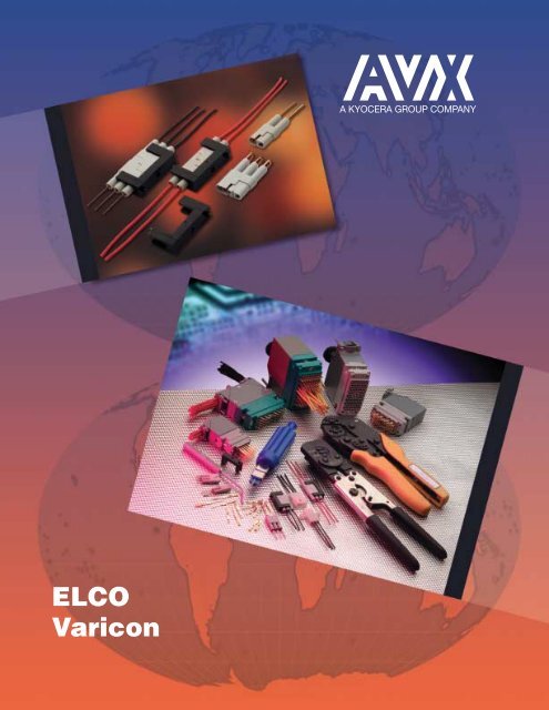
ELCO Varicon
ELCO Varicon
ELCO Varicon
- No tags were found...

You also want an ePaper? Increase the reach of your titles
YUMPU automatically turns print PDFs into web optimized ePapers that Google loves.
Portable Rent Supplement Program2010 Rent Ceiling GuidePosted: June 2010Lower Mainland Bachelor 1 Bed 2 Bed 3 Bed 4 Bed 5 BedVan. – W. End/Downtown 1015 1201 1863 2773Van. – S. Granville/Oak 873 1177 1570 2019Van. – Kitsilano/Point Grey 908 1119 1562 2147Van. – Westside/Kerrisdale 883 1167 1801 2757Van. – Marpole 752 880 1143 1201Van. – Mount Pleasant /Renfrew Heights793 876 1144 1573Van. – E. Hastings 807 899 1194 1426Van. – Southeast Vancouver 828 934 1289 1276Version 11780 (Mar09) 2550 (Sep09)Burnaby 781 930 1177 1436 1760 (Mar09) 2390 (Jul08)Delta 645 801 1025 1231 * *New Westminster 697 831 1059 1334 * 1910 (Jul08)North Vancouver City 879 989 1228 1623 *North Vancouver District 903 1053 1345 16492610 (Nov09)Richmond 789 983 1207 1502 1730 (Jan09) *Surrey 644 778 976 1224 * *Tri-Cities 703 832 1058 1510 * *West Vancouver 1010 1283 1959 2637 2810 (Nov09) *White Rock 767 877 1082 1473 * *Abbotsford 578 613 697 715Chilliwack 525 659 831 985Langley City/Dist. 683 822 960 1184 1670 (Apr10)Maple Ridge/Pitt Meadows 600 737 942 1189*2190 (Jun09)6 bedroomMission 552 No Data * 635 682Squamish 579 785 922 1048 * *Gibsons * 678 795 1018 1184 * *Sechelt * 608 728 854 1058 * *Bachelor, 1, 2, & 3 Bedroom rates are determined by adding 10% to the average value for the communities found in the CMHC Rental MarketReports for Fall/December 2009.Figures shown in italics are calculated by BC Housing for areas and/or bedroom sizes where CMHC provides no current data. These figuresreflect an average rate based on a survey of rents conducted by BC Housing. These calculations will not be reviewed in less than 12 months. All4 & 5 bedroom rates fall into this category.Figures shown on gray background reflect latest available data, collected prior to 2004. CMHC no longer publishes for these municipalities.* If you need data for an area or bedroom size highlighted in gray, not listed or shown as “No data”, contact BC Housing for assistance withdetermining an appropriate rent ceiling.Page 1 of 4g:\windata\rsupplem\lists\cmhc rates\2009\2010ceilings~v1.doc
The <strong>Varicon</strong> RangePitchNumber of Body Termination Current SeriesContacts Style Types Rating Number(Amps)Staggered, Fixed:0.050" 2 to 152 Plugs and Receptacles5 8218Solder, Eyelet0.050" 18, 30, 36, 42, 54, 72 Plugs and ReceptaclesStaggered, Fixed: Straight &Right Angle Solder, Eyelet5 8219Staggered,0.075" x 0.130" Removable: Taper Tab,& 20, 38, 56, 90, 120 Plugs and Receptacles Eyelet, 880160.075" x 0.150" Wire Wrap,75, 100, 130 Crimp 80170.100" 17, 23, 29, 35, 41 Receptacles As Series 7024 8 70080.100" 17, 23, 29, 35, 41, 47 PlugsStaggered,Fixed: Solder6 70220.100" 17, 23, 29, 35, 41, 47 ReceptaclesStaggered,Fixed: Solder6 7023Staggered,Fixed: Solder,0.100" 17, 23, 29, 35, 41 Receptacles Taper Tab, 8 7024Eyelet,Wire Wrap,Bus LineStaggered,Removable: Taper Tab,0.100" 17, 23, 29, 35, 41, 47 Receptacles Eyelet, 8 7038Wire Wrap,Crimp0.100" 33, 75, 117, 165 Plugs and ReceptaclesWire Wrap,Crimp5 8026Square Grid Dual Row,Fixed: Straight and Right0.100" 24, 48, 72, 96 Plugs and ReceptaclesAngle Solder,Eyelet,5 8223Wire Wrap, CrimpWrappable Removable4mm 50, 64 Plug and Receptacle Crimp 2 8014In-line0.200" 2, 3 Plugs and Receptacles Fixed: Solder 8.5 8020CrimpIn-line0.200" 3 Plug and Receptacle Fixed: Solder 8.5 8022Crimp2 <strong>ELCO</strong>
<strong>Varicon</strong> ®IntroductionElco’s <strong>Varicon</strong> product range is available as two-piece input /output and board level connectors (intermateable plugs andreceptacles). <strong>Varicon</strong> contacts are also available in strips, ondisposable carriers, ready for staking to p.c. cards. They alluse the famous, fork-like <strong>Varicon</strong> ® (fixed) or Varilok ®(insertable / removable) hermaphroditic contact design.VARICON DESIGN ADVANTAGESElco’s hermaphroditic <strong>Varicon</strong> contact utilizes a fork-likedesign incorporating four large mating surfaces that arecoined to achieve exceptional hardness and smoothness.The mating surfaces are wedged together by the spring-likedesign of the contact and by the innate properties of thecontact material. The <strong>Varicon</strong> contact has proven its reliabilityin innumerable applications and with over one-million contactsbeing produced daily, billions of successful, trouble-freeoperating hours have been logged.FEATURES• Four intimate contact areas, electrically parallel• High current carrying capability, excellent heat dissipation• Self-cleaning, wiping action burnishes contacting surfacesreducing constrictive resistance• Low contact resistance 3 to 4 milliohms• Stable in vibration and adverse environments• High contact normal pressure achieved at low stresslevelsHIGH RELIABILITYThe mating surfaces provide a gas-tight connection andresists corrosion caused by adverse environments. This sealis made possible by the spring-like properties of the <strong>Varicon</strong>contact and by the smoothness of the coined matingsurfaces. After being mated for years, the contacts still retainclean, unoxidized mating surfaces.LOW RESISTANCEBecause of the spring-like properties of the <strong>Varicon</strong> contact,both sides of the contact are always under considerablepressure when mated. Their sliding and wiping actionburnishes the surfaces in a self-cleaning action reducing anyconstrictive resistance. The low contact resistance remainsa permanent feature of the <strong>Varicon</strong> contact even after thousandsof mating and unmating cycles.HIGH CURRENT CAPACITYThe low contact resistance contributes substantially to<strong>Varicon</strong>’s high current-carrying capacitor. Also, its heat-dissipatingcharacteristics are enhanced by its flat configuration.SHOCK AND VIBRATION RESISTANCEShould external forces cause any decrease in contact pressurebetween two of the four mating surfaces, it is automaticallycompensated by redistributing the contact pressurebetween the other two mating surfaces.ECONOMY<strong>Varicon</strong> contacts are stamped from sheet stock instead ofscrew-machined. Consequently, this production method notonly increases the production capacity but decreases productioncost as there is little waste.VERSATILITYThe <strong>Varicon</strong> concept can be used in a card-mounted plugthat mates with a receptacle, or <strong>Varicon</strong> contacts can bestaked directly to a pc board and soldered into place. Thislatter method eliminates the need for a conventional plugreducing the cost of the connection system while retainingthe proven reliability of the <strong>Varicon</strong> interconnection.CONTACT TYPESTwo basic sizes of our <strong>Varicon</strong> contact are available: standardand miniature <strong>Varicon</strong>. And each size has two majorvariations: the fixed <strong>Varicon</strong> contact and the Varilokinsertable / removable version. The standard size is rated at8 amps and has a withdrawal force range of 2 to 16 ouncesper contact. The miniature size is specifically for high densityapplications and is rated at 5 amps with a withdrawal forceof 2 to 8 ounces per contact. (For exact specifications, checkthe individual series listing.)Miniature <strong>Varicon</strong> ®Approx. 2X Actual SizeStandard <strong>Varicon</strong> ® 3<strong>ELCO</strong>
<strong>Varicon</strong> ®IntroductionCONTACT MATERIALThe primary contact material used is phosphor bronze. Theelectrical conductivity of copper alloys are extremely good.Within the <strong>Varicon</strong> concept, the contacts must also performas springs and these alloys offer the elastic properties andthe endurance required by today’s rugged applications.CONTACT PLATINGA nickel underplate of 50 to 100 microinches, followed by aminimum of 10 microinches of gold plate is Elco’s standardcontact plating. The gold plate prevents the formation ofinsulating oxide films while the nickel plate provides a hardbacking. It, in turn, reduces wear on the gold and preventsdiffusion between the gold and base metal. Other platingthicknesses, such as those required by military specifications,can be supplied on request.VARILOK CRIMP-AND-INSERTCONTACTSThe crimp-termination, insertable / removable Varilok contactoffers a solderless connection between wire and contact aswell as strain relief for the wire. This contact snaps into theinsulator quickly and easily. With our simple tool it can beremoved without difficulty, yet it locks securely into place andcannot twist or bend out of alignment.Loose Varilok ContactsReel-Mounted Varilok ContactsVarilok contacts also are available with wire-wrappable, solderand taper-tab tail configurations. Available loose for smallscale production and replacement purposes, the Varilokcontact is also supplied on reels for use with fast, economicalautomatic crimping machines reducing man-hourrequirements and production costs in medium and largescaleproduction runs. Because the contact can be crimpedto the wire and installed into the insulator at any point duringthe manufacturing operation, it offers the user convenienceand flexibility. Reels contain 1800 standard contacts or 3000miniature contacts.4 <strong>ELCO</strong>
<strong>Varicon</strong> ®IntroductionMINI-VARILOKThe Mini-Varilok is half the size of the standard Varilokcontact. It’s designed for hand or machine crimping to solidor stranded AWG #22 to #30 wire. Its basic features areidentical to the standard Varilok however it also incorporatesa decreased insertion force and is used for high densityapplications. Production methods for the Mini-Varilok are thesame as the standard Varilok.CONTACT RETENTIONThe Varilok contact, after undergoing five insertion / extractioncycles and being subjected to the vibration and shocktests of MIL-C-28731, still withstands an axial load in excessof 10 pounds (6 for mini-varilok).WIRE SIZEThe Varilok contact with its open crimp barrel conforms topractically all specifications written for screw-machined contactswith closed crimp barrels. The crimp barrel of theVarilok contact is designed to accommodate wire sizes AWG#18 to #26. It’s also possible to crimp together two stranded#22 or smaller wires. The Mini-Varilok accommodateswire sizes AWG #22 to #30. Table I lists the various sizes ofwire to which Varilok contacts can be crimped, and indicatesthe minimum conductor diameter and the maximum insulatordiameter that can be accommodated by the contacts.The crimp barrel is also crimped to the wire’s insulation forstrain relief and the large, overlapping ears of the barrelaccommodate a wide range of wire insulation sizes (Table I).For an optimum crimp connection, the insulation is strippedone-eighth inch from the end of the conductor.Table IWire Sizes(AWG)(Ref: MIL-W-16878/4 – Type E wire)Conductor InsulatorSingle Varilok Mini-Varilok Diameter DiameterWire (Nominal) (Max. Overall)#18 Yes No .048 .074#20 Yes No .038 .062#22 Yes Yes .030 .054#24 Yes Yes .024 .048#26 Yes Yes .019 .043#28 No Yes .015 .039#30(Stranded) No Yes .012 .036CRIMP CHARACTERISTICSThe illustration shows an enlarged cross-section of a typicalVarilok crimp on a #22 stranded wire. No significant voidsare visible. The complete deformation of the wire strandsindicates optimum contact between the contact barrel andthe conductors.TENSILE STRENGTHTable II lists the values, in pounds, of tensile strength (wirepull-out force) for Varilok and Mini-Varilok contacts crimpedto stranded AWG #18 to #30 wires.Wire Size(AWG)StrandedWireTable IITensile Strength(In Pounds)#18 #20 #22 #24 #26 #28 #3040 25 15 10 5 3 1.5CRIMPING EQUIPMENTAll equipment needed to crimp Varilok and Mini-Varilokcontacts is normally available from stock. Crimping equipmentfor production crimping as well as hand-operatedcrimping pliers are designed to realize the full electrical,mechanical and economical advantages of the Varilok andMini-Varilok contact.<strong>ELCO</strong>5
<strong>Varicon</strong> ®Series 8014Elco has introduced a new, metric version of the famous<strong>Varicon</strong> connector. The wire to board 8014 series is availablein 50 or 64 positions and suitable for use in a VME front plate.The <strong>Varicon</strong> contact is well known for high reliability anddurability under all conditions. Contacts are specified at 2amps and low contact resistance. In the 8014 series, thefamiliar hermaphroditic contact is shrouded on both sides toprotect and guide the contact to a perfect mating. Boardtermination is right angle or vertical to plated through holes.The connectors have actuating screws to assist mating andunmating and to provide secure attachment. The covershave integral cable clamps. The 50 position cover is plasticand 64 position is die cast aluminum.TECHNICAL SPECIFICATIONSNumber of Contacts:50, 64Contact Spacing:4.0mmCurrent Rating:2Amp/pinVoltage Rating:125VDielectric WithstandingVoltage:2000V rms/min.Durability:200 cycleApplicable Wire Size:AWG #18~#26Operating Temperature:-55~+105°CMATERIAL / FINISHInsulator:Plug PBTRec. PBTContact:Phosphor BronzeFinish / Gold over NickelHardware:see individual drawing6 <strong>ELCO</strong>
<strong>Varicon</strong> ®Series 8014ORDERING CODE (64 pos. Center-Screw Type Plug)10 8014 264 XXXXXXVariation 1 /Variation 2 /Contact CodeFinish, Color000 = No contact loaded 000 = without cover, centerscrew,green insulator100 = Wire crimp contact(loose pieces attached) 100 = with cover, centerscrew,green 200 = Straight through holeinsulator<strong>ELCO</strong>7
<strong>Varicon</strong> ®Series 8014ORDERING CODE (64 pos. Center-Screw Type Receptacle)20 8014 264 XXXXXXVariation 1 /Variation 2 /Contact CodeFinish, Color000 = No contact loaded 000 = R/A through hole,100 = Wire crimp contact center lock nut,(loose pieces attached) green insulator200 = Straight through hole 100 = ST through hole,999 = Right angle through center lock nut,holegreen insulator8 <strong>ELCO</strong>
<strong>Varicon</strong> ®Series 8014ORDERING CODE (50 pos. Side-Screw, Plug)10 8014 350 XXXXXXVariation 1 /Variation 2 /Contact CodeFinish, Color000 = No contact loaded 028 = Side-screw,100 = Wire crimp contact gray insulator(loose pieces attached) 128 = Side-screw,200 = Straight through hole gray insulatorwith cover(038 = Side-short-screw,gray insulator. . . .special)<strong>ELCO</strong>9
<strong>Varicon</strong> ®Series 8014ORDERING CODE (50 pos. Side-Screw Receptacle)20 8014 350 999028Variation 1 /Contact Code999 = Right angle throughholeVariation 2 /Finish, Color028 = Side-screw,gray insulatorORDERING CODE (Crimp Contact)70 8014 000 000 858Finish Code858 = 10 microinchesGold over Nickel Plate10 <strong>ELCO</strong>
<strong>Varicon</strong> ®Series 8014ORDERING CODE (Cover, 64 pos. Center-Screw, Aluminum Die Cast)30 8014 001 000 225ORDERING CODE (50 pos. Side-Screw, Plastic (gray))30 8014 001 003 008<strong>ELCO</strong>11
<strong>Varicon</strong> ®Series 8016 – .075" x .130" x .150" Grid PatternFEATURES• Available in five sizes: 20, 38, 56, 90 and 120 contacts• Insertable / removable Varilok contacts• Crimp, solder, solderless wrap, and taper tab terminations• Exceptional versatility: all hardware can be mounted onplug or receptacle (see ordering code)• Actuating screw facilitates mating and unmating, locksmated connectors together• Polarizing hardware can be set to any of six positions atfactory; can also be reset by user (see polarizing code)• Optional cover with top or side cable entry and clamp• Optional cable strain relief clamp with adjustable strapfor large or small cable bundles (fits on sizes 38 and 56)• Plug and receptacle contacts are protected from mishandling• Guide pins and sockets ensure correct alignment whenmating• U.L. recognized polyester material• Aluminum covers• CSA acceptable polyester material• QPL approved polyester materialCABLE STRAIN RELIEF CLAMP• Adjustable for large or small cable bundles• Versatile clamp assembly permits mounting in variousdirections. Can be mounted on plug and/or receptacle.• Order Number 30-8026-9601 for plug and cable-tocableapplications• Order Number 30-8026-9602 for receptacle applications• Available for sizes 38 and 56.300.400.300.025TECHNICAL SPECIFICATIONSCurrent Rating:8 amperes, maximumContact Resistance:6 milliohms, maximumContact Material:Phosphor bronzeContact Plating:Gold, 10 microinches min.,over Nickel,50-100 microinchesInsulator Material:Thermoplastic 94V-O glassfilled polyesterInsulation Resistance:5,000 megohms, min.(polyester)Sea Level: 1250 volts RMS3.4" Hg: 625 volts RMSCover and Clamp Materialand Finish:Aluminum with clear chromateunder grey enamel finishCommercial Specification:Covered under the componentsrecognition program ofUnderwriters’ Laboratory, Inc.File No. E-2761012 <strong>ELCO</strong>
<strong>Varicon</strong> ®Series 8016 – Rectangular Connector – 20 WayPLUGActuatingScrewPLUGFixedNutSOCKETActuatingScrewSOCKETFixedNutPIN LAYOUT20WayORDERING CODE008016020217 001CONNECTOR PLUG ANDRECEPTACLE COMBINATIONSPrefixSeriesNumberNumber ofContactsContact TerminationSeeVariationCode*000 = Contacts not fitted and ordered separately,see page 23 for full list of optionsPlug001/501/601002/502/602Receptacle007/507/607008/508/608909/509/609910/510/610911/511/611912/512/612217 = Solder 0.098" x 2.49mm218 = Wire Wrap –0.025 x 0.050 x 0.567" / 0.64 x 1.27 x 14.4mm296 = Wire Wrap –0.025 x 0.026 x 0.579" / 0.64 x 1.27 x 19.3mm903/503/603904/504/604905/505/605906/506/606504 = Solder Tail –VARIATION CODE750 = Wire Wrap –0.025 x 0.050 x 0.760" / 0.64 x 1.27 x 19.3mm*Crimp contacts always ordered separately.See page 23 for details.Select variation code combinations marked with square in the table.European Version USA Versions CoverInsulator Grey Polyester Grey Polyester Green Polyester and Actu-Body Aluminum No No No Cable ating FixedType Cover Cover Cover Cover Cover Cover Entrance Screw Nut— 001 — 501 601 None Yes NoMale— 002 — 502 602 None No Yes(Exposed 903 — 503 603 Top* Yes NoContacts) 904 — 504 604 Side* Yes No905 — 505 605 Top* No Yes906 — 506 606 Side* No Yes— 007 507 607 None No YesFemale — 008 508 608 None Yes No(Recessed 909 — 509 — 609 — Top* Yes NoContacts) 910 — 510 — 610 — Side* Yes No911 — 511 — 611 — Top* No Yes912 — 512 — 612 — Side* No Yes*These covers should only be used with crimp contacts.<strong>ELCO</strong>13
<strong>Varicon</strong> ®Series 8016 – Rectangular Connector – 20 WayCLAMPING AND COVER DIMENSIONSRECOMMENDED LAYOUTFOR FRONT CHASSISMOUNTING & PCB LAYOUT3.816.3516.26Ø2.4432.3924.3810 AT 1.90= 19.004.77Ø3.5028.58 ±0.1310.41 ±0.13STANDARD COVERSCover Part NumberNumber Cable ClampMetric ScrewsImperial ScrewsEuropean VersionUSA Versionof Contacts Entrance Description Size mm (inches)30-8016-9829-20-000 30-8016-9829-00-000 20 Side Standard 11.53 (0.454) Dia.30-8016-9831-20-000 30-8016-9831-00-000 20 Top Standard 11.53 (0.454) Dia.REMOVABLE SIDE PLATE COVERS14 <strong>ELCO</strong>millimeters (inches)Cover Number of Cable ClampPart Number Contacts Entrance Description Minimum Size Maximum Size30-8016-020-000-413 20 Side/Top Standard 5 x 10 (0.197 x 0.394) 10 x 10 (0.394 x 0.394)30-8016-020-000-415 20 45° Standard 5 x 10 (0.197 x 0.394) 10 x 10 (0.394 x 0.394)30-8016-020-000-423 20 Dual 90° Side/Top Special 2 - 5 x 10 (0.197 x 0.394) 2 - 10 x 10 (0.394 x 0.394)30-8016-020-000-425 20 Dual 45° Entry Special 2 - 5 x 10 (0.197 x 0.394) 2 - 10 x 10 (0.394 x 0.394)
<strong>Varicon</strong> ®Series 8016 – Rectangular Connector – 38 WayPLUGActuatingScrewPLUGFixedNutSOCKETActuatingScrewSOCKETFixedNutPIN LAYOUT38WayORDERING CODE00Prefix8016SeriesNumber038Number ofContacts217 001Contact TerminationSeeVariationCode*000 = Contacts not fitted and ordered separately,see page 23 for full list of options217 = Solder 0.098" x 2.49mm218 = Wire Wrap –0.025 x 0.050 x 0.567" / 0.64 x 1.27 x 14.4mm296 = Wire Wrap –0.025 x 0.026 x 0.579" / 0.64 x 1.27 x 19.3mmCONNECTOR PLUG ANDRECEPTACLE COMBINATIONSPlugReceptacle001/501/601002/502/602903/503/603904/504/604905/505/605906/506/606919/519/619920/520/620921/521/621922/522/622007/507/607008/508/608909/509/609910/510/610911/511/611912/512/612923/523/623924/524/624925/525/625926/526/626935/535/635936/536/636937/537/637938/538/638504 = Solder Tail –750 = Wire Wrap –0.025 x 0.050 x 0.760" / 0.64 x 1.27 x 19.3mm*Crimp contacts always ordered separately.See page 23 for details.VARIATION CODE931/531/631932/532/632933/533/633934/534/634Select variation code combinations marked with square in the table.European Version USA Version Cover & Actu-Insulator Grey Polyester Grey Polyester Green Polyester Cable ating FixedBody Type Aluminum Cover No Cover Aluminum Cover No Cover Aluminum Cover No Cover Entrance Screw NutStd. Large Ex-Large Std. Large Ex-Large Std. Large Ex-LargeClamp Clamp Clamp Clamp Clamp Clamp Clamp Clamp Clamp— — — 001 — — — 501 — — — 601 None Yes NoMale— — — 002 — — — 502 — — — 602 None No Yes(Exposed 903 919 931 — 503 519 531 — 603 619 631 — Top Yes NoContacts) 904 920 932 — 504 520 532 — 604 620 632 — Side Yes No905 921 933 — 505 521 533 — 605 621 633 — Top No Yes906 922 934 — 506 522 534 — 606 622 634 — Side No Yes— — 007 — — — 507 — — — 607 None No Yes— — 008 — — — 508 — — — 608 None Yes NoFemale 909 923 935 — 509 523 535 — 609 623 635 — Top Yes No(Recessed 910 924 936 — 510 524 536 — 610 624 636 — Side Yes NoContacts) 911 925 937 — 511 525 537 — 611 625 637 — Top No Yes912 926 938 — 512 526 538 — 612 626 638 — Side No Yes<strong>ELCO</strong>15
<strong>Varicon</strong> ®Series 8016 – Rectangular Connector – 56 WayPLUG - Actuating ScrewSOCKET - Actuating ScrewPIN LAYOUT56WayPLUG – Fixed NutSOCKET – Fixed NutORDERING CODE00Prefix8016SeriesNumber056Number ofContacts217 001SeeVariationCodeContact Termination*000 = Contacts not fitted and ordered separately,see page 23 for full list of options217 = Solder 0.098" x 2.49mm218 = Wire Wrap –0.025 x 0.050 x 0.567" / 0.64 x 1.27 x 14.4mm296 = Wire Wrap –0.025 x 0.026 x 0.579" / 0.64 x 1.27 x 19.3mm504 = Solder Tail –750 = Wire Wrap –0.025 x 0.050 x 0.760" / 0.64 x 1.27 x 19.3mm*Crimp contacts always ordered separately.See page 23 for details.CONNECTOR PLUG ANDRECEPTACLE COMBINATIONSPlugReceptacle001/501/601002/502/602903/503/603904/504/604905/505/605906/506/606919/519/619920/520/620921/521/621922/522/622007/507/607008/508/608909/509/609910/510/610911/511/611912/512/612923/523/623924/524/624925/525/625926/526/626935/535/635936/536/636937/537/637938/538/638931/531/631932/532/632933/533/633934/534/634Select variation code combinations marked with square in the table.VARIATION CODEEuropean Version USA Version Cover & Actu-Insulator Grey Polyester Grey Polyester Green Polyester Cable ating FixedBody Type Aluminum Cover No Cover Aluminum Cover No Cover Aluminum Cover No Cover Entrance Screw NutStd. Large Ex-Large Std. Large Ex-Large Std. Large Ex-LargeClamp Clamp Clamp Clamp Clamp Clamp Clamp Clamp Clamp— — — 001 — — — 501 — — — 601 None Yes NoMale— — — 002 — — — 502 — — — 602 None No Yes(Exposed 903 919 931 — 503 519 531 — 603 619 631 — Top Yes NoContacts) 904 920 932 — 504 520 532 — 604 620 632 — Side Yes No905 921 933 — 505 521 533 — 605 621 633 — Top No Yes906 922 934 — 506 522 534 — 606 622 634 — Side No Yes— — 007 — — — 507 — — — 607 None No Yes— — 008 — — — 508 — — — 608 None Yes NoFemale 909 923 935 — 509 523 535 — 609 623 635 — Top Yes No(Recessed 910 924 936 — 510 524 536 — 610 624 636 — Side Yes NoContacts) 911 925 937 — 511 525 537 — 611 625 637 — Top No Yes912 926 938 — 512 526 538 — 612 626 638 — Side No Yes<strong>ELCO</strong>17
<strong>Varicon</strong> ®Series 8016 – Rectangular Connector – 56 WayCLAMPING AND COVER DIMENSIONSRECOMMENDED LAYOUTFOR FRONT CHASSISMOUNTING & PCB LAYOUT19.816.351.68 Ø3.797.2464.3151.133.816 AT 3.30= 19.816 AT 3.30= 19.81Ø5.5057.91 ±0.13STANDARD COVERSOPTIONAL REMOVABLE SIDE PLATE COVER11.89 ±0.138 AT1.90 = 15.24Cover Part NumberNumber of Cable ClampMetric ScrewsImperial ScrewsEuropean VersionUSA VersionContacts Entrance Description Size mm (inches)30-8016-9823-20-000 30-8016-9823-00-000 56 Side Standard 16.51 X 12.70 (0.650 x 0.500)30-8016-9824-20-000 30-8016-9824-00-000 56 Top Standard 16.51 X 12.70 (0.650 x 0.500)30-8016-9827-20-000 30-8016-9827-00-000 56 Side Large 16.51 X 15.44 (0.650 x 0.608)30-8016-9828-20-000 30-8016-9828-00-000 56 Top Large 16.51 X 15.44 (0.650 x 0.608)30-8016-9840-20-000 30-8016-9840-00-000 56 Side Extra-Large 20.83 X 15.60 (0.820 x 0.614)30-8016-9842-20-000 30-8016-9842-00-000 56 Top Extra-Large 20.83 X 15.60 (0.820 x 0.614)REMOVABLE SIDE PLATE COVERS18 <strong>ELCO</strong>millimeters (inches)Cover Number of Cable ClampPart Number Contacts Entrance Description Minimum Size Maximum Size30-8016-056-000-413 56 Side/Top Standard 6 x 14 (0.236 x 0.551) 17 x 14 (0.669 x 0.551)30-8016-056-000-415 56 45° Standard 6 x 14 (0.236 x 0.551) 17 x 14 (0.669 x 0.551)30-8016-056-000-423 56 Dual 90° Side/Top Special 2 - 6 x 14 (0.236 x 0.551) 2 - 17 x 14 (0.669 x 0.551)30-8016-056-000-425 56 Dual 45° Entry Special 2 - 6 x 14 (0.236 x 0.551) 2 - 17 x 14 (0.669 x 0.551)
<strong>Varicon</strong> ®Series 8016 – Rectangular Connector – 90 WayPLUG - Actuating ScrewSOCKET - Actuating ScrewPIN LAYOUT90WayPLUG – Fixed NutSOCKET – Fixed NutORDERING CODE008016090217 001CONNECTOR PLUG ANDRECEPTACLE COMBINATIONSPrefixSeriesNumberNumber ofContactsContact TerminationSeeVariationCode*000 = Contacts not fitted and ordered separately,see page 23 for full list of options217 = Solder 0.098" x 2.49mm218 = Wire Wrap –0.025 x 0.050 x 0.567" / 0.64 x 1.27 x 14.4mm296 = Wire Wrap –0.025 x 0.026 x 0.579" / 0.64 x 1.27 x 19.3mmPlugReceptacle001/501/601002/502/602903/503/603904/504/604905/505/605906/506/606931/531/631932/532/632933/533/633934/534/634007/507/607008/508/608909/509/609910/510/610911/511/611912/512/612935/535/635936/536/636937/537/637938/538/638504 = Solder Tail –750 = Wire Wrap –0.025 x 0.050 x 0.760" / 0.64 x 1.27 x 19.3mm*Crimp contacts always ordered separately.See page 23 for details.Select variation code combinations marked with square in the table.VARIATION CODEEuropean Version USA Version Cover & Actu-Insulator Grey Polyester Grey Polyester Green Polyester Cable ating FixedBody Type Cover No Cover Cover No Cover Cover No Cover Entrance Screw NutLarge Ex-Large Large Ex-Large Large Ex-LargeClamp Clamp Clamp Clamp Clamp Clamp— — 001 — — 501 — — 601 None Yes NoMale— — 002 — — 502 — — 602 None No Yes(Exposed 903 931 — 503 531 — 603 631 — Top Yes NoContacts) 904 932 — 504 532 — 604 632 — Side Yes No905 933 — 505 533 — 605 633 — Top No Yes906 934 — 506 534 — 606 634 — Side No Yes— — 007 — — 507 — — 607 None No Yes— — 008 — — 508 — — 608 None Yes NoFemale 909 935 — 509 535 — 609 635 — Top Yes No(Recessed 910 936 — 510 536 — 610 636 — Side Yes NoContacts) 911 937 — 511 537 — 611 637 — Top No Yes912 938 — 512 538 — 612 638 — Side No Yes<strong>ELCO</strong>19
<strong>Varicon</strong> ®Series 8016 – Rectangular Connector – 90 WayCLAMPING AND COVER DIMENSIONSRECOMMENDED LAYOUTFOR FRONT CHASSISMOUNTING & PCB LAYOUT28.587.931.72 Ø3.795.8867.8152.0714 AT 3.30 = 46.20Ø6.7557.96 ±0.1319.43 ±0.1312 AT1.90 = 22.86STANDARD COVERSCover Part NumberNumber of Cable ClampMetric Screws Imperial ScrewsContacts EntranceEuropean VersionUSA VersionDescription Size mm (inches)30-8016-9832-20-000 30-8016-9832-00-000 90 Side Large 20.32 (0.800) Dia.30-8016-9833-20-000 30-8016-9833-00-000 90 Top Large 20.32 (0.800) Dia.30-8016-9843-20-000 30-8016-9843-00-000 90 Side Extra-Large 25.40 x 20.32 (1.00 x 0.008)30-8016-9844-20-000 30-8016-9844-00-000 90 Top Extra-Large 25.40 x 20.32 (1.00 x 0.008)OPTIONAL REMOVABLE SIDE PLATE COVERREMOVABLE SIDE PLATE COVERS20 <strong>ELCO</strong>millimeters (inches)Cover Number of Cable ClampPart Number Contacts Entrance Description Minimum Size Maximum Size30-8016-090-000-413 90 Side/Top Standard 7 x 21 (0.276) 21 x 21 (0.827 x 0.827)30-8016-090-000-415 90 45° Standard 7 x 21 (0.276) 21 x 21 (0.827 x 0.827)30-8016-090-000-423 90 Dual 90° Side/Top Special 2 - 7 x 21 (0.276) 2 - 21 x 21 (0.827 x 0.827)30-8016-090-000-425 90 Dual 45° Entry Special 2 - 7 x 21 (0.276) 2 - 21 x 21 (0.827 x 0.827)
<strong>Varicon</strong> ®Series 8016 – Rectangular Connector – 120 WayPLUG - Actuating ScrewSOCKET - Actuating ScrewPIN LAYOUT120WayPLUG – Fixed NutSOCKET – Fixed NutORDERING CODE00Prefix8016SeriesNumber120Number ofContacts217 001Contact TerminationSeeVariationCode*000 = Contacts not fitted and ordered separately,see page 23 for full list of options217 = Solder 0.098" x 2.49mm218 = Wire Wrap –0.025 x 0.050 x 0.567" / 0.64 x 1.27 x 14.4mm296 = Wire Wrap –0.025 x 0.026 x 0.579" / 0.64 x 1.27 x 19.3mmCONNECTOR PLUG ANDRECEPTACLE COMBINATIONSPlug001/501/601002/502/602503/603504/604505/605506/606531/631532/632533/633534/634Receptacle007/507/607008/508/608509/609510/610511/611512/612535/635536/636537/637538/638504 = Solder Tail –750 = Wire Wrap –0.025 x 0.050 x 0.760" / 0.64 x 1.27 x 19.3mm*Crimp contacts always ordered separately.See page 23 for details.Select variation code combinations marked with square in the table.VARIATION CODEEuropean Version USA Version Cover & Actu-Insulator Grey Polyester Grey Polyester Green Polyester Cable ating FixedBody Type Cover No Cover Cover No Cover Cover No Cover Entrance Screw NutLarge Ex-Large Large Ex-Large Large Ex-LargeClamp Clamp Clamp Clamp Clamp Clamp— — 001 — — 501 — — 601 None Yes NoMale— — 002 — — 502 — — 602 None No Yes(Exposed 503 531 — 503 531 — 603 631 — Top Yes NoContacts) 504 532 — 504 532 — 604 632 — Side Yes No505 533 — 505 533 — 605 633 — Top No Yes506 534 — 506 534 — 606 634 — Side No Yes— — 007 — — 507 — — 607 None No Yes— — 008 — — 508 — — 608 None Yes NoFemale 509 535 — 509 535 — 609 635 — Top Yes No(Recessed 510 536 — 510 536 — 610 636 — Side Yes NoContacts) 511 537 — 511 537 — 611 637 — Top No Yes512 538 — 512 538 — 612 638 — Side No Yes<strong>ELCO</strong>21
<strong>Varicon</strong> ®Series 8016 – Rectangular Connector – 120 WayCLAMPING AND COVER DIMENSIONSRECOMMENDED LAYOUTFOR FRONT CHASSISMOUNTING & PCB LAYOUT4.137.9336.07Ø3.797.0568.2352.0714 AT 3.30 = 46.2060.33 ±0.13Ø6.7522.23 ±0.1316 AT1.90 = 30.48STANDARD COVERSCover Part Number Number of Cable ClampImperial Screws Contacts Entrance Description Size mm (inches)30-8016-9834-00-000 120 Side Large 20.32 x 27.43 (0.800 x 1.080)30-8016-9835-00-000 120 Top Large 20.32 x 27.43 (0.800 x 1.080)30-8016-9845-00-000 120 Side Extra-Large 27.94 x 27.56 (1.100 x 1.085)30-8016-9846-00-000 120 Top Extra-Large 27.94 x 27.56 (1.100 x 1.085)NB: There are no removable side plate covers for the 120 Way version.22 <strong>ELCO</strong>
Varilok ®Loose ContactsVarilok ® connectors can be specified as either fully loaded, toinclude the connector body and a variety of pre-loadedcontact termination types or the empty body and a selectionof separately specified and ordered contacts. The tablebelow details the various loose contacts available.Contact Style Description Plating Specification Order Code*Ordered separatelyCrimp Contact 0.25µM Gold All Over (Standard) 60 8017 0313 00 339Loose 0.25µM Gold Nose & Tail (Optional) 60 8017 0313 00 042Ordered separatelyTail Section – 2.49 x 0.61 (0.098 x 0.024)Tail Section – 1.27 x 0.63 (0.025 x 0.005)If fitted type 218Tail Section – 1.27 x 0.63 (0.025 x 0.005)If fitted type 750Tail Section – 0.635 x 0.63 (0.025 x 0.005)If fitted type 296*If fitted type 217Crimp Contact End Carrier 0.25µM Gold All Over (Standard) 60 8017 0323 99 339(1800 Contacts per reel) 0.25µM Gold Nose & Tail (Optional) 60 8017 0323 99 0420.25µM Gold All Over (Standard) 60 8017 0323 00 339**0.25µM Gold Nose & Tail (Optional) 60 8017 0323 00 042**Solder Tag Contact 0.25µM Gold All Over (Standard) 60 8017 0513 00 33914.4mm Maxiwrap Contact 0.25µM Gold All Over (Standard) 60 8017 0613 00 33919.3mm Maxiwrap Contact 0.25µM Gold All Over (Standard) 60 8017 0623 00 33914.0 Miniwrap Contact 0.25µM Gold All Over (Standard) 60 8017 0633 00 339Tail Section – 0.635 x 0.63 (0.025 x 0.005)4.3mm PC Solder Contact*If fitted type 504for ø 1.00 mm P.T.H.* Indicates standard contact** Order code to be used when purchasing through a USA source.0.25µM Gold All Over (Standard) 60 8017 0663 00 339Plating code 343 conforms to MIL SPEC requirementCONNECTOR POLARIZATION<strong>Varicon</strong> ® 8016 Series connectors are designed with an integralpolarizing system to ensure in high density environmentsthat the correct halves are mated together.As a factory standard, male plugs are set to the codeP-G-1-G-1, with the female receptacles being set to theopposite matching code R-S-1-S-1.Customers who need to use this facility can either configurethe polarization codes themselves, or for an additionalcharge provide AVX with the required polarization codes forpresetting by the factory, which will be supplied as a specialpart 58-8016-XXX-000-XXX.ORDERING CODEPG1G1Type of Connector HalfPlug = PSocket = RLocation Side(Large Dia.)Guide Pin = GGuide Socket = SPositions1 through 6Location Side(Small Dia.)Guide Pin = GGuide Socket = SPositions1 through 6<strong>ELCO</strong>23
<strong>Varicon</strong> ®Series 801775/100/130 CONTACTSPlug withPlug withActuating Screw 001 Fixed Screw 00275 CONTACTSPlugReceptacle100 CONTACTSPlugReceptacleReceptacle withReceptacle withFixed Nut 007 Actuating Nut 008130 CONTACTSPlugReceptacleORDERING CODE008017XXXXXX0XXRECOMMENDED CHASSIS LAYOUTPrefixSeriesNumberNumber ofPositions75, 100, 130Contact Code217 = Solder 0.098" x 2.49mm –60 8017 0513 00 339218 = Wire Wrap –0.025 x 0.050 x 0.567" / 0.64 x 1.27 x 14.4mm60 8017 0613 00 339750 = Wire Wrap –0.025 x 0.050 x 0.760" / 0.64 x 1.27 x 19.3mm60 8017 0623 00 339296 = Wire Wrap –0.025 x 0.026 x 0.579" / 0.64 x 0.66 x 14.7mm60 8017 0633 00 339SeeVariationCode313 = Wire Crimp (Contacts Loose) –Must be ordered separately60 8017 0313 00 339No. of Front Chassis Mtg. Back Chassis Mtg.Pos. B C D B C D75 2.500/63.50 1.953/49.61 1.437/36.50 2.500/63.50 2.953/75.00 1.656/42.06100 3.100/78.74 2.546/64.67 1.437/36.50 3.100/78.74 3.562/90.47 1.656/42.06130 3.700/93.98 3.156/80.16 1.437/36.50 3.700/93.98 4.156/105.56 1.656/42.06Dimensions inches/mm323 = Wire Crimp (1800 Contacts on a Reel) –60 8017 0323 99 339Must be ordered separatelyCONNECTOR PLUGAND RECEPTACLECOMBINATIONSVARIATION CODEInsulator Variation Cover &Body Code Cable Actuating FixedType No. Entrance Screw Screw001 No Yes No002 No No YesPlug 003 Top Yes No004 Side Yes No005 Top No Yes006 Side No Yes24Insulator Variation Cover &Body Code Cable Fixed ActuatingType No. Entrance Nut Nut007 No Yes No008 No No YesReceptacle009 Top Yes No010 Side Yes No011 Top No Yes012 Side No Yes<strong>ELCO</strong>Plug001002003004005006Receptacle007008009010011012
<strong>Varicon</strong> ®ToolsCONTACT INSERTION TOOLSThese are small hand tools which provide a positive method forinserting contacts into the rear of the insulator by applying pressureon the contacts directly to the end of the insulation crimp.ToolContact Capability06 1742 0400 00 000 Varilok ®No. 60 8017 Family06 7698 01 000 0000 Mini Varilok ®No. 60 8216 FamilyContact Insertion ToolHAND CRIMP TOOLSThis tool is designed for hand crimping of contacts. The tool is well suited for maintenance,model shop, laboratory and small scale production purposes. Two crimping cavities areavailable; Upper Cavity will crimp wire 18-20 AWG and the Lower Cavity will crimp wire22-26 AWG.VARILOCK ® Hand Crimp ToolMINI VARILOCK ® Hand Crimp ToolPart No. Contact Capability Wire Type & Size06 7852 7002 01 000 Varilok ® Stranded AWGNo. 60 8017 0313 No. 18-26Mini Varilok ®Stranded AWG06 7858 01 000 0000 No. 60 8216 0313 No. 22-30CONTACT EXTRACTION TOOLSThis tool is designed to extract contacts from the front ofthe insulator quickly and easily, without damage to eithercontacts or insulator.Contact Extraction ToolToolContact Capability06 1877 0400 00 000 Varilok ®No. 60 8017 Family06 7699 01 000 0000 Mini Varilok ®No. 60 8216 FamilyCRIMPING MACHINESThese heavy duty crimping machinesare designed for fast and economicalproduction-line crimping of contactssupplied on reels. The machinesincorporate the unique DIALMATICcrimp adjustment which permits themachine operator to crimp contactsto wires of different sizes by simplyadjusting two knobs.SPECIFICATIONSPress Rating: 3 Ton CapacityPower: 240V AC, 50 CyclesPart No. Contact Wire SizeHR-1 06 1984 0100 Varilok ® AWG No. 18-26HR-3 06 7705 0100 Mini Varilok ® AWG No. 22-30<strong>ELCO</strong>25
<strong>Varicon</strong> ®Series 8026 – 0.100" Rectangular ConnectorFEATURES• Economical miniature high-density connectors suitable forhigh-reliability and military applications.• 0.100" (2.54mm) square grid rack and panel connectorswith male and female insulators are available in four sizes:33, 75, 117 and 165 contacts.• Insertable / removable mini-varilok and mini-wrap contacts.• Crimp and/or solderless wrap terminations.• Exceptional versatility: all hardware can be mounted onplug or receptacle (see ordering code).• Actuating screw facilitates mating and unmating; locksmated connectors together.• Keyed and shrouded insulator design prevents incorrectmating and protects contacts from mishandling.• Simplified polarizing hardware permits 36 polarizationcombinations per connector pair.• Optional covers with top or side cable entry and clamp.• Optional cable clamps.• Choice of any combination of hardware — or no hardware.• U.L. recognized-diallyl phthalate material.• QPL approved-diallyl phthalate material.TECHNICAL SPECIFICATIONSCONTACTSCurrent Rating:5 amperesContact Resistance:6 milliohmsWithdrawal Force:2 to 8 ounces max. per contactMaterial:Phosphor BronzeORDERING CODE00 8026 033Standard Plating:Gold, 10 microinches min.,over Nickel,50-100 microinchesSpacing:0.100" (2.54mm)INSULATORSInsulation Resistance:5,000 megohms, min.(diallyl phthalate insulators)5,000 megohms, min.(polycarbonate insulators)000Dielectric WithstandingVoltage:Sea Level: 1,000 Volts rmsMaterials:0.100" (2.54mm) spacing –diallyl phthalate, glass-filled,flame resistant803Number ofContacts033 = 33075 = 75117 = 117165 = 165Contact CodeOrder crimp contactsseparately by Part Number.Otherwise specify contact code 491.000 = Crimp (3000 - contact reel)Part Number60 8216 0323 00 339000 = Crimp (loose contact)Accepts #22-30 AWG wireVariation CodeAdd 050 to order alternativekeying (Pin & Socket)i.e. 701 = Standard hermaphroditickeying751 = Pin and socket keyingComplete a 15 digit assembly numberfor each mating part, male and female.26 <strong>ELCO</strong>Part Number60 8216 0313 00 339491 = Wire wrappable removable contact .025"(.635mm) sq. x .564" (14.33mm) tailPart Number60 8216 0413 00 339
<strong>Varicon</strong> ®Series 8026 – 0.100" Rectangular ConnectorVARIATION CODESInsulatorBodyTypeMale(ExposedContacts)Female(RecessedContacts)InsulatorBodyTypeVariationCodeNo.33 ContactsTable 1Actuating Fixed KeyingScrew Nut HardwareCover701 Yes No Yes No702 Yes No No No703 No Yes Yes No704 No Yes No No733 No No Yes No734 No No No No801 No Yes Yes No802 No Yes No No803 Yes No Yes No804 Yes No No No833 No No Yes No834 No No No NoVariationCodeNo.33 ContactsTable 2Actuating Fixed KeyingNut Nut HardwareCoverMale 501 Yes No Yes No(Exposed 502 Yes No No NoContacts) 503 No Yes Yes No504 No Yes No No601 No Yes Yes NoFemale602 No Yes No No(Recessed603 Yes No Yes NoContacts)604 Yes No No No75, 117 & 165 ContactsTable 3Variation Code No.Insulator Without Cover Cover Cable Actuating Fixed KeyingBody Cover Small Large Entrance Screw Nut HardwareTypeClamp Clamp701 — — No Yes No Yes702 — — No Yes No No703 — — No No Yes Yes704 — — No No Yes No733 — — No No No Yes734 — — No No No No— 705 713 Top Yes No Yes— 706 714 Side Yes No YesMale — 707 715 Top Yes No No(Exposed — 708 716 Side Yes No NoContacts) — 709 717 Top No Yes Yes— 710 718 Side No Yes Yes— 711 719 Top No Yes No— 712 720 Side No Yes No— 735 739 Top No No Yes— 736 740 Side No No Yes— 737 741 Top No No No— 738 742 Side No No No801 — — No No Yes Yes802 — — No No Yes No803 — — No Yes No Yes804 — — No Yes No No833 — — No No No Yes834 — — No No No No— 805 813 Top No Yes Yes— 806 814 Side No Yes YesFemale — 807 815 Top No Yes No(Recessed — 808 816 Side No Yes NoContacts) — 809 817 Top Yes No Yes— 810 818 Side Yes No Yes— 811 819 Top Yes No No— 812 820 Side Yes No No— 835 839 Top No No Yes— 836 840 Side No No Yes— 837 841 Top No No No— 838 842 Side No No No<strong>ELCO</strong>Table 4Variation Code No.Insulator Without Cover Cover Cable Actuating Fixed KeyingBody Cover Small Large Entrance Nut Screw HardwareTypeClamp Clamp501 — — No Yes No Yes502 — — No Yes No No503 — — No No Yes Yes504 — — No No Yes No— 505 513 Top Yes No Yes— 506 514 Side Yes No YesMale — 507 515 Top Yes No No(Exposed — 508 516 Side Yes No NoContacts) — 509 517 Top No Yes Yes— 510 518 Side No Yes Yes— 511 519 Top No Yes No— 512 520 Side No Yes No601 — — No No Yes Yes602 — — No No Yes No603 — — No Yes No Yes604 — — No Yes No No— 605 613 Top No Yes Yes— 606 614 Side No Yes YesFemale — 607 615 Top No Yes No(Recessed — 608 616 Side No Yes NoContacts) — 609 617 Top Yes No Yes— 610 618 Side Yes No Yes— 611 619 Top Yes No No— 612 620 Side Yes No No27
<strong>Varicon</strong> ®Series 8026 – 0.100" Rectangular Connector33 CONTACTSFemale Plug (Recessed Contacts)For variation code numberSee Table 1 See Table 2Page 27 Page 2775 CONTACTSFemale Plug (Recessed Contacts)For variation code numberSee Table 3 See Table 4Page 27 Page 27COVER CROSS REFERENCE, FOR DETAILS SEE 8016 CONNECTORClampCoverCableNumber Entrance Description8026/.100"(2.54mm) sq.30-8016-9821 Side Small 75 Pin30-8016-9822 Top Small 75 Pin30-8016-9823 Side Small 117 Pin30-8016-9824 Top Small 117 Pin30-8016-9825 Side Large 75 Pin30-8016-9826 Top Large 75 Pin30-8016-9827 Side Large 117 Pin30-8016-9828 Top Large 117 Pin30-8016-9832 Side Large 165 PinClampCoverCableNumber Entrance Description8026/.100"(2.54mm) sq.30-8016-9833 Top Large 165 Pin30-8016-9838 Side Ex-Large 75 Pin30-8016-9839 Top Ex-Large 75 Pin30-8016-9840 Side Ex-Large 117 Pin30-8016-9842 Top Ex-Large 117 Pin30-8016-9843 Side Ex-Large 165 Pin30-8016-9844 Top Ex-Large 165 Pin30-8016-9845 Side Ex-Large —30-8016-9846 Top Ex-Large —28 <strong>ELCO</strong>
<strong>Varicon</strong> ®Series 8026 – 0.100" Rectangular Connector117 CONTACTS Female Plug (Recessed Contacts)For variation code numberSee Table 3 See Table 4Page 27 Page 27165 CONTACTS Female Plug (Recessed Contacts)For variation code numberSee Table 3 See Table 4Page 27 Page 27POLARIZATION CODEPolarizing pins, when desired, are factory set in position #1.Customer can reset as shown below, use tool No. 06 198902. To order factory settings other than position #1, fill outPLS5the “Polarizing Code” below and submit it along with thecompleted connector ordering code.RS3Insulator Body TypeP = Male, R = FemaleLeft Side PinPOLARIZATION / KEYINGLeft Side Pin Position1 through 6Right Side PinALTERNATIVE KEYINGEXAMPLE (PIN & SOCKET)Right Side Pin Position1 through 6<strong>ELCO</strong>NOTE: Same size of pin and socket keying hardware are usedon all existing 8026 connectors (33, 75, 117, 165) – both sides29
<strong>Varicon</strong> ®Series 8223 – 0.100" Dual Row Square GridFEATURES• Wide range of contact terminations including wirewrapping, P.C. solder tail, wire hole, wire crimp• For 1 ⁄16", 3 ⁄32" P.C. card• Polarity and keying are built into the connector bodyto prevent mismating• Perpendicular or parallel connector mounting• Proven <strong>Varicon</strong> ® contact reliability• Protected male; recessed female contactsTECHNICAL SPECIFICATIONSCONTACTSCurrent Rating:5 amperes with 22 AWG wireContact Resistance:6 milliohms, maximumContact Material and Plating:Phosphor BronzeNickel plate, 50 to 100 microinches,followed by gold plate.10 microinches minimumORDERING CODE00 8223 024 000Number of Contacts024, 048, 072 & 096INSULATORSMaterial:Diallyl Phthalate, glass-filled,flame resistant, per MIL-M-14-F,Type SDGFInsulation Resistance:5,000 megohms, minimumContact Code001Variation CodeDielectric WithstandingVoltage:Sea Level: 1,000 Volts rmsInsertion/Withdrawal Force:2 to 8 ounces per contactUse three digit code number when contacts are tobe factory installed. If contacts are to be suppliedloose, or contact tails to be formed, use three zeros(000) in contact code section. Note that the wirecrimp tail contacts can only be ordered as separateitems by part numbers.Code Profile Description Part No.H BoardDim. Thk. Fig.Coined Tail Formed 60 8223 0223 .080 1000 90° after installing 60 8223 0213 .062(Max. 0236 Diag.)Coined Tail Formed 60 8223 0243000 90° after installing 60 8223 0253.093 1(Max. 0236 Diag.)473P.C. Tail Coined(Max. 0236 Diag.)60 8223 0233 .400 2519P.C. Tail Coined(Max. 0236 Diag.)60 8223 0213 .279 2520P.C. Tail Coined(Max. 0236 Diag.)60 8223 0223 .479 2558 P.C. Tail Coined 60 8223 0243 .309 2559 (Max. 0236 Diag.) 60 8223 0253 .509 2722Wire Hole Tail(.032 x .050)60 8200 1613 .162 3721 P.C. Tail .020 Sq. 60 8200 1623 .228 4736 P.C. Tail .020 Sq. 60 8200 1633 .259 4AccessoriesGuide Pins Sockets (R)ReferInsulator Variation Contact Style ThreadedTo BoardType Cover BracketKeying Figure ThicknessLocking Lkg. Kyg.001 Formed Contact Terminal X 1.080 2.03.062 1.57Male PC Terminal X 2(Exposed 002 Wire Hole Terminal X 3Contacts) PC Straight Terminal X 4003Crimp Contact X 5Wrappable Removable X 6004 Formed Contact Terminal X 1 .093 2.36901 Formed Contact Terminal X 1.080 2.03.062 1.57Female PC Terminal X 2(Exposed 902 Wire Hole Terminal X 3Contacts) PC Straight Terminal X 4903Crimp Contact X 5Wrappable Removable X 6904 Formed Contact Terminal X 1 .093 2.36737 P.C. Tail .020 Sq. 60 8200 1643 .541 4753 P.C. Tail .020 Sq. 60 8200 1653 .103 4771 P.C. Tail .020 Sq. 60 8200 1663 .462 4000Crimp Contact(Reel 3000) 60 8216 0323522-30 AWG000Crimp Contact (Loose)22-30 AWG60 8216 0313 5491Wrappable/Removable 60 8216 0413 .560 6Contact (.025 Sq.)30 <strong>ELCO</strong>
<strong>Varicon</strong> ®Series 8223 – 0.100" Dual Row Square GridMALE INSULATORSCRIMPTYPEFEMALE INSULATORSCRIMPTYPEMOUNTING LAYOUTPanel for Figures 2, 3, & 4 P.C. Board for Figure 1MOUNTING HARDWARE(See drawings for correct assembly of hardware.Hardware shown is supplied with each board mountedconnector.)Panel for Figures 5 & 6 P.C. Board for Figures 2, 3, & 4KEY TO DIAGRAMSNo. ofContactsA B C D E F G H S24 1.1 2.2 1.4 1.9 1.27 1.252 1.26 Pg. 26 1.23648 2.3 3.4 2.6 3.1 2.47 2.452 2.46 Pg. 26 2.43672 3.5 4.6 3.8 4.3 3.67 3.652 3.66 Pg. 26 3.63696 4.7 5.8 5.0 5.5 4.87 4.852 4.86 Pg. 26 4.836Item Size Part # Unified Thread55 #2 90-0502-0031-11-05356 #2-5 90-0602-0121-11-05358 #2-5 90-0902-0136-11-053Item Size Part #70 #2-5 60-8223-4562-11-06271 #2-5 60-8223-4522-11-06272 #2-5 60-8223-4662-11-06273 #2-5 60-8223-4662-11-062<strong>ELCO</strong>31
Varilok ®Series 8020 – Cable ConnectorAPPLICATIONIn line connection of 2 or 3 wire of 18-26 AWG, insulationø1.03 mm to 1.88 mm.FEATURES AND BENEFITS• 2 and 3 position in single row• Uses identical molding for plug and socket• Uses identical contact for plug and socket• Uses standard <strong>Varicon</strong> 8016 contacts• Uses standard <strong>Varicon</strong> Crimping Tools, ContactExtraction Tools and Insertion Tools• Has combined nylon mounting and locking clipcommon to both sizes• Contacts for both solder and crimp terminationTECHNICAL SPECIFICATIONSContact:Single row of 2 or 3 Varilok contactsConfiguration:On a 0.200 inch pitch, 5.08 mmCONNECTOR DIMENSIONS (mm)Contact Rating:8.5 amperesContact Resistance:6 milliohms (max)Insulation Resistance:5,000 megohms (min)Voltage Proof:2,500 volts R.M.S. Sea LevelLOCKING CLIP DIMENSIONS (mm)2 way connector 3 way connectorhousinghousing00Locking clip2 way assemblyORDERING CODEFOR COMPLETE CONNECTORS WITH NON-CRIMP CONTACTS FITTED80200022173 way assembly001PrefixSeries NumberNumber of Contacts002 = Two way003 = Three way*Contact terminations should be insulated because they may protrude from the insulator.NB: See page 23 for details of contacts.32 <strong>ELCO</strong>*Contact Termination217 = Solder Tag218 = Wire Wrap(0.61 x 1.27 x 14.4mm)296 = Mini Wire Wrap(0.61 x 0.66 x 4.73mm)504 = Solder Tail(0.61 x 0.66 x 4.32mm)Variation CodeORDERING CODE FOR HOUSINGS AND CRIMP CONTACTSDescription Part Number Description Part Number2 way connector: Housing only 60-8020-3117-00-000 0.25µM Gold reeled crimp contacts (gold all over) 60-8017-0323-99-3393 way connector: Housing only 60-8020-3317-00-000 0.25µM Gold reeled crimp contacts (selective) 60-8017-0323-99-0420.25µM Gold loose crimp contacts (gold all over) 60-8017-0313-00-339 NB: See page 23 for details of crimp contacts0.25µM Gold loose crimp contacts (selective) 60-8017-0313-00-042 Locking clip 60-8020-3210-00-000
Varilok ®Series 8022 – Cable ConnectorAPPLICATIONIn line connection of 3 wires of 18-26 AWG, insulation ø1.03mm to 1.88 mm.FEATURES• 3 position in single row• Male insulator incorporates two positive locking armsfor up to 1.6 mm thick panel mount• Uses identical contact for plug and socket• Uses standard <strong>Varicon</strong> 8016 contacts (8017 Series)• Uses standard <strong>Varicon</strong> Crimping Tools, ContactExtraction Tools and Insertion Tools• Has mounting and locking clip mechanism• Contacts for both solder and crimp terminationTECHNICAL SPECIFICATIONSContact Spacing:5.08 mmContact Rating:8.5 amperesContact Resistance:6 milliohms (max)Insulation Resistance:5K megohmsVoltage Proof:2.5K volts R.M.S. Sea LevelOperating Temperature:-55°C to 125°CPlugPanel CutoutPART NUMBERSPlug Molding: 60 8022 3218 00 000Socket Molding: 60 8022 3318 00 000Crimp Contacts (loose): 60 8017 0313 00 339 See page 23 for detailsCrimp Contacts (reel): 60 8017 0323 00 339 of crimp contacts<strong>ELCO</strong>Socket33
<strong>Varicon</strong> ®Series 8218 – 0.050" Staggered Dual RowFEATURES• High contact density• For parallel or perpendicular p.c. card mounting• High mounting density (.050" centers, minimum)• Nylon end sections for mounting and card guidance• Mounting hardware supplied with connector• Mates with 8219 SeriesTECHNICAL SPECIFICATIONSCurrent Rating:5 amperes, maximumContact Resistance:0.005 ohm, maximumContact Material and Plating:Phosphor Bronzenickel plate, 30 to 50 microinches followed bygold plate, 10 to 20 microinchesInsulator Material:Diallyl phthalate, glass-filled, flame resistant,end guides: nylonInsulation Resistance:5,000 megohms, minimumORDERING CODE00 8218 100 000Dielectric Withstanding Voltage:Sea Level: 1000 Volts rms3.4" Hg: 500 Volts rmsInsertion/Withdrawal Force:2 to 16 ounces per contact004Number of Contacts002 to 076 for connectorswithout center guideContact CodeVariant 002 right angled contacts000 = 60 8200 16 33P.C. Tail000 = 60 8200 16 63P.C. TailVariants 001 and 005722 = 60 8200 16 13Wire Hole Tailwith keying pins011 = Receptacle012 = Plug-Card/pininserted inodd position013 = Plug-Card/pininserted in evenposition017 = Plug-BoardVariation Code001 = Receptacle002 = Plug-Card005 = Plug-Boardwith keying holes021 = Receptacle022 = Plug-Card/pininserted inodd position023 = Plug-Card/pininserted in evenposition027 = Plug-Board736 = 60 8200 16 33P.C. Tail (X = 9/32", Y = 1/4")753 = 60 8200 16 53P.C. Tail (X = 1/8", Y = 3/32")771 = 60 8200 16 63P.C. Tail (X = 31/64", Y = 29/64")34 <strong>ELCO</strong>
<strong>Varicon</strong> ®Series 8218 – 0.050" Staggered Dual RowReceptacle Variation 001 Plug Variation 002 Plug Variation 005RECEPTACLE 001 – MATES WITH PLUGS 002 AND 005MOUNTING LAYOUTVariation 001 and 005 Variation 002Minimum Center to CenterSpacing for Adjustment PlugsDIMENSIONSA B C D E(inches)(No. of contacts x “A” dimension “A” dimension “A” dimension “A” dimension0.050") - 0.050" + 0.300" + 0.440" + 0.550" + 0.690"POLARIZATIONKeying Ordering No.60-8218-4715-00-148Determine polarization pin location from views.P = Specify location by contact # where polarizing pin must be inserted.H = Specify location by contact # where contact must be omitted for mating.Typical Example: 00-8218-024-721-001-P-17 (polarizing pin mtd. in position 17)00-8218-024-721-005-H-17 (polarizing hole is in position 17)<strong>ELCO</strong>35
<strong>Varicon</strong> ®Series 8219 – 0.050" Staggered Dual RowFEATURES• For p.c. card-to-card applications• High contact density• Low withdrawal force contacts• Rugged, color coded end guides• Parallel or perpendicular p.c. board mounting• Mates with Series 8218TECHNICAL SPECIFICATIONSCurrent Rating:5 amperes, maximumContact Resistance:6 milliohms, maximumContact Material and Plating:Phosphor BronzeGold, 10 microinches minimum,over nickel, 50 to 100 microinchesInsulator Material:Diallyl phthalate, glass-filled, flame resistantper MIL-M-14F, Type SDGF.Guidance Hardware:Left hand guides: Metal, gold colorRight hand guides: Metal, silver colorInsulation Resistance:5,000 megohms, minimumDielectric Withstanding Voltage:Sea Level: 1000 Volts rms3.4" Hg: 500 Volts rmsInsertion/Withdrawal Force:2 to 8 ounces per contactORDERING CODE00 8219 042722001Number of Contacts018, 030, 036, 042, 054, 072Contact Code(see below)Variation CodeFor Variation = 001Code “X”No. Contact Type Dim.722 Wire hole tail .187721 P. C. solder tail .250736 P. C. solder tail .281737 P. C. solder tail .562753 P. C. solder tail .125771 P. C. solder tail .484CodeNo.For Variation = 002Contact Type000 P. C. solder tails formed722 Wire hole tail unformedFor Variation = 005CodeNo. Contact Type“Y”Dim.722 Wire hole tail .157721 P. C. solder tail .219736 P. C. solder tail .250737 P. C. solder tail .531753 P. C. solder tail .093771 P. C. solder tail .453POLARIZING SYSTEMWithoutKeying001 = Receptacle002 = Plug, parallel board mounting005 = Plug, perpendicular board mountingNOTE: Connector is supplied withmounting screws or eyelets, as applicable(see drawings).Contact Factory for Special Variations.36 <strong>ELCO</strong>When Keying is ordered with part number, the Key is installed at the factory.
<strong>Varicon</strong> ®Series 8219 – 0.050" Staggered Dual RowDIMENSIONS:millimeters (inches)NumberRef.Ref.of A B CE F GDKContacts18 17 .850 (0.033) 1.150 (0.045) 1.290 (0.051) 1.400 (0.055) 1.540 (0.061) .964 (0.038) 1.300 (0.051)30 29 1.450 (0.057) 1.750 (0.069) 1.890 (0.075) 2.000 (0.079) 2.140 (0.084) 1.564 (0.061) 1.900 (0.075)36 35 1.750 (0.069) 2.050 (0.080) 2.190 (0.086) 2.300 (0.091) 2.440 (0.096) 1.864 (0.073) 2.220 (0.087)42 41 2.050 (0.080) 2.350 (0.093) 2.490 (0.098) 2.600 (0.102) 2.740 (0.108) 2.164 (0.085) 2.500 (0.098)54 53 2.650 (0.104) 2.950 (0.116) 3.090 (0.122) 3.200 (0.126) 3.340 (0.131) 2.764 (0.109) 3.100 (0.122)72 71 3.550 (0.140) 3.850 (0.152) 3.990 (0.157) 4.100 (0.161) 4.240 (0.167) 3.664 (0.144) 4.000 (0.157)RECEPTACLE 001 MATES WITH PLUGS 002 AND 005MOUNTING LAYOUTS*When used in metal panel with Code Contact 722 cut out diam. Is .210".<strong>ELCO</strong>37
<strong>Varicon</strong> ®Series 7008 – 0.100" Staggered Dual RowFEATURES• Available with or without card guides• Many sizes• Wide range of contact terminations• For 1 ⁄16" thick PCB• Polarization insert• Mates with Series 7000 and 7022 PlugsTECHNICAL SPECIFICATIONSCurrent Rating:10 amperesContact Resistance:6 milliohms, maximumContact Material and Plating:Phosphor Bronze per QQ-B-750,Composition A.Gold, 10 microinches minimum,over nickel, 30 to 100 microinchesInsulator Material:Diallyl phthalate, glass-filled,flame resistant, per MIL-M-14F,Type SDGF.Insulation Resistance:25,000 megohms, minimumDielectric Withstanding Voltage:Sea Level: 2000 Volts rms3.4" Hg: 675 Volts rmsInsertion/Withdrawal Force:2 to 16 ounces per contactORDERING CODE00 7008 017146001Number of Contacts017, 023, 029, 035, 041Contact CodeSee table.Variation Code141 = 60 7001 06 33P.C. Termination for 1/8" Card146 = 60 7001 13 13.078" Base Taper Tab156 = 60 7001 18 13Wire wrapping (.026 x .062 x .600")163 = 60 7001 19 13.098" Base Taper Tab w/Wire Hole165 = 60 7001 20 13Forked Tail Solder Termination for Bus Line Connection(.056 x .125" Slot)Card Card CodeSlot Guides1/16" Yes 001No 002AvailabilityConnectorNo. of ContactsDescription 17 23 29 35 41With Guides – for 1/16" Card X X X X XWithout Guides – for 1/16" Card X X X X X166 = 60 7001 20 23Dual Solder Termination for 2 Wires or Bus Line(.056 x .125" Slot)189 = 60 7004 02 13Conventional Solder Termination for 3 Wires38 <strong>ELCO</strong>
<strong>Varicon</strong> ®Series 7008 – 0.100" Staggered Dual RowDIMENSIONS:NumberLA B C D E FG* HN*of+.010Contacts Bottom 1/16" Card Con. N-Con. ±.003 –.000 Con. N-Con. .17 1.920 (0.076) 2.134 (0.084) 2.40 (0.094) 1.835 (0.072) .074 (0.003) .531 (0.021) .468 (0.018) .343 (0.014) 1.600 (0.063) 1.900 (0.075) .210 (0.008) .148 (0.006)23 2.520 (0.099) 2.734 (0.108) 3.00 (0.118) 2.435 (0.096) .074 (0.003) .531 (0.021) .468 (0.018) .343 (0.014) 2.200 (0.087) 2.500 (0.098) .210 (0.008) .148 (0.006)29 3.120 (0.123) 3.334 (0.131) 3.60 (0.142) 3.035 (0.119) .074 (0.003) .531 (0.021) .468 (0.018) .343 (0.014) 2.800 (0.110) 3.100 (0.122) .210 (0.008) .148 (0.006)35 3.270 (0.129) 3.934 (0.134) 4.20 (0.165) 3.635 (0.143) .074 (0.003) .531 (0.021) .468 (0.018) .343 (0.014) 3.400 (0.134) 3.700 (0.146) .210 (0.008) .148 (0.006)41 4.320 (0.170) 4.534 (0.179) 4.80 (0.190) 4.235 (0.167) .074 (0.003) .531 (0.021) .468 (0.018) .343 (0.014) 4.000 (0.157) 4.300 (0.169) .210 (0.008) .148 (0.006)*N-CON = Non-Conductive Chassis(1/16" Clearance Around Contacts)P.C. CARD LAYOUTCON = Conductive Chassis(1/8" Clearance Around Contacts)millimeters (inches)CHASSIS MOUNTING<strong>ELCO</strong>39
<strong>Varicon</strong> ®Series 7022 – 0.100" Staggered Dual RowFEATURES• Insulator rigidity reduces p.c. card warp• Insulator maintains exact spacing between contacts• Reduces cost of card punching operation (fewer holes)• Reduces cost of contact staking operation (oneoperation instead of two)• Reduces assembly time (no plastic strip to remove)• For 1 ⁄16" or 3 ⁄32" p.c. card• Mates with Series 7000 Receptacles with or withoutcard guidesTECHNICAL SPECIFICATIONSCurrent Rating:10 amperesContact Resistance:6 milliohms, maximumContact Material and Plating:Phosphor Bronze per QQ-B-750,Composition A.Gold, 10 microinches minimum,over nickel, 30 to 100 microinchesInsulator Material:Diallyl phthalate, glass-filled, perMIL-M-14F, Type SDGF.Variation 001/002Thermoplastic PolycarbonateVariation 003Insulation Resistance:25,000 megohms, minimumDielectric Withstanding Voltage:Sea Level: 2000 Volts rms3.4" Hg: 675 Volts rmsInsertion/Withdrawal Force:2 to 16 ounces per contactORDERING CODE00 7022 023000 001Number of Contacts017, 023, 029, 035, 041For Series 7008 receptacleVariation Code001 = 1/16" Module Card Thickness002 = 3/32" Module Card Thickness003 = 1/16" Module Card ThicknessMOUNTING LAYOUT60 7001 2913 for 1/16" Card 60 7001 2813 for 1/16" Card60 7001 2923 for 3/32" Card 60 7001 2823 for 3/32" Card40 <strong>ELCO</strong>
<strong>Varicon</strong> ®Series 7023 – 0.100" Staggered Dual RowFEATURES• Guide pins facilitate mating, ensure correct alignment• Insulator rigidity reduces p.c. card warp• Insulator maintains exact spacing between contacts• Reduces cost of card punching operation (fewer holes)• Reduces cost of contact staking operation (oneoperation instead of two)• Reduces assembly time (no plastic strip to remove)• For 1 ⁄16" or 3 ⁄32" p.c. card• Mates with Series 7024 and 7038 ReceptaclesTECHNICAL SPECIFICATIONSCurrent Rating:10 amperesContact Resistance:6 milliohms, maximumContact Material and Plating:Phosphor Bronze per QQ-B-750,Composition A.Gold, 10 microinches minimum,over nickel, 30 to 100 microinchesInsulator Material:Diallyl phthalate, glass-filled, flame resistantper MIL-M-14F, Type SDGF.Variation 001/002/110/111Thermoplastic PolycarbonateVariation 003Insulation Resistance:25,000 megohms, minimumDielectric Withstanding Voltage:Sea Level: 1800 Volts rms3.4" Hg: 675 Volts rmsInsertion/Withdrawal Force:2 to 16 ounces per contactORDERING CODE00 7023 023000 001MOUNTING LAYOUTNumber of Contacts017, 023, 029, 035, 041, 047Diallyl PhthalateGlass Filled1/16" Card 3/32" Card 1/16" Card001 002 003110 111Contacts used in this connector:Card Upper Card Lower CardContacts Contacts1/16" 60 7001 29 13 60 7001 28 133/32" 60 7001 29 23 60 7001 28 23DIMENSIONS:millimeters (inches)NumberCof B Max. HContacts17 2.200 (0.087) 2.470 (0.097) 1.600 (0.063)23 2.800 (0.110) 3.070 (0.121) 2.200 (0.087)29 3.400 (0.134) 3.670 (0.144) 2.800 (0.110)35 4.000 (0.157) 4.270 (0.168) 3.400 (0.134)41 4.600 (0.181) 4.870 (0.192) 4.000 (0.157)47 5.200 (0.205) 5.470 (0.215) 4.600 (0.181)<strong>ELCO</strong>41
<strong>Varicon</strong> ®Series 7024 – 0.100" Staggered Dual RowFEATURES• Guide sockets facilitate mating, ensure correct alignment• Open-ended card slot; use with p.c. card of any width• Wide range of contact terminations• Many sizes available• For 1 ⁄16" or 3 ⁄32" p.c. card• Mates with Series 7023 PlugTECHNICAL SPECIFICATIONSCurrent Rating:10 amperesContact Resistance:6 milliohms, maximumContact Material and Plating:Phosphor Bronze per QQ-B-750,Composition A.Gold, 10 microinches minimum,over nickel, 30 to 100 microinchesInsulator Material:Diallyl phthalate, glass-filled,flame resistant, per MIL-M-14F,Type SDGF.Insulation Resistance:25,000 megohms, minimumDielectric Withstanding Voltage:Sea Level: 1800 Volts rms3.4" Hg: 675 Volts rmsInsertion/Withdrawal Force:2 to 16 ounces per contactORDERING CODE00 7024 023163001Number of Contacts017, 023, 029, 035, 041Contact CodeSee table.Variation Code001 = 1/16" Thick Card002 = 3/32" Thick Card110 = 1/16" Thick Card111 = 3/32" Thick Card141 = 60 7001 06 33P.C. Termination for 1/8" Card146 = 60 7001 13 13.078" Base Taper Tab156 = 60 7001 18 13Wire wrapping (.026 x .062 x .600")AvailabilityConnectorNo. of ContactsDescription 17 23 29 35 41For 1/16" Card X X X X XFor 3/32" Card X X X X X163 = 60 7001 19 13.098" Base Taper Tab w/Wire Hole165 = 60 7001 20 13Forked Tail Solder Termination for Bus Line Connection(.056 x .125" Slot)166 = 60 7001 20 23Dual Solder Termination for 2 Wires or Bus Line(.056 x .125" Slot)189 = 60 7004 02 13Conventional Solder Termination for 3 Wires42 <strong>ELCO</strong>
<strong>Varicon</strong> ®Series 7024 – 0.100" Staggered Dual RowDIMENSIONS:millimeters (inches)Number ±.003E ±.002G††of A B C DF HN††Contacts Max. 1/16" Card 3/32" Card Con. N-Con. Con. N-Con.17 1.900 (0.075) 2.300 (0.091) 2.570 (0.101) 1.185 (0.072) .074 (0.003) .105 (0.004) 17/32" .468 (0.018) .343 (0.014) 1.600 (0.063) .208 (0.008) .146 (0.006)23 2.500 (0.098) 2.900 (0.114) 3.170 (0.125) 2.435 (0.096) .074 (0.003) .105 (0.004) 17/32" .468 (0.018) .343 (0.014) 2.200 (0.087) .208 (0.008) .146 (0.006)29 3.100 (0.122) 3.500 (0.138) 3.770 (0.148) 3.035 (0.119) .074 (0.003) .105 (0.004) 17/32" .468 (0.018) .343 (0.014) 2.800 (0.110) .208 (0.008) .146 (0.006)35 3.700 (0.146) 4.100 (0.161) 4.370 (0.172) 3.635 (0.143) .074 (0.003) .105 (0.004) 17/32" .468 (0.018) .343 (0.014) 3.400 (0.134) .208 (0.008) .146 (0.006)41 4.300 (0.169) 4.700 (0.185) 4.970 (0.196) 4.235 (0.167) .074 (0.003) .105 (0.004) 17/32" .468 (0.018) .343 (0.014) 4.000 (0.157) .208 (0.008) .146 (0.006)†† N-CON = Non-Conductive Chassis(1/16" Clearance Around Contacts)CON = Conductive Chassis(1/8" Clearance Around Contacts)MOUNTING LAYOUT<strong>ELCO</strong>43
<strong>Varicon</strong> ®Series 7038 – 0.100"Staggered Dual Row, Crimp ContactsFEATURES• Varilok ® contacts are insertable and removableby user• Crimp, solderless wrap, tapered tab, and wire holeterminations available• All crimping, insertion, and extraction equipmentavailable• Guide sockets facilitate mating, ensure correctalignment• Open-ended card slot; no p.c. card notchingnecessary• Mates with Series 7023 PlugTECHNICAL SPECIFICATIONSCurrent Rating:8 amperesContact Resistance:6 milliohms, maximumContact Material and Plating:Phosphor BronzeGold, 10 microinches minimum,over nickel, 50 to 100 microinchesInsulator Material:Diallyl phthalate, glass-filled,flame resistant, per MIL-M-14F,Type SDGF.Insulation Resistance:5,000 megohms, minimumDielectric Withstanding Voltage:Sea Level: 1800 Volts rms3.4" Hg: 675 Volts rmsInsertion/Withdrawal Force:2 to 16 ounces per contactORDERING CODE00 7038 023000001Number of Contacts017, 023, 029,035, 041, 047217 = 60 8017 05 13Wire HoleContact CodeSee table.Variation Code001 = 1/16" Thick Card002 = 3/32" Thick Card110 = 1/16" Thick Card111 = 3/32" Thick Card218 = 60 8017 06 13Solderless Wrap Tail – .025" x .050" x .567"750 = 60 8017 06 23Solderless Wrap Tail – .025" x .050" x .760"296 = 60 8017 06 33Solderless Wrap Tail – .025" x .025" x .580"504 = 60 8017 06 63Solderless Wrap Tail – .025" x .025" x .170"*000 = 60 8017 03 13Wire Crimp Tail (Contacts Loose) 18-26 AWG*000 = 60 8017 03 23Wire Crimp Tail(Contacts on a Reel) 18-26 AWG*Order separately by part number, refer to page 2344 <strong>ELCO</strong>
<strong>Varicon</strong> ®Series 7038 – 0.100"Staggered Dual Row, Crimp ContactsDIMENSIONS:millimeters (inches)Numberof A B C D E F G JContacts Max. 1/16" Card 3/32" Card17 1.900 (0.075) 2.300 (0.091) 2.570 (0.101) 1.890 (0.075) .074 (0.003) .105 (0.004) 17/32" .571 (0.022) 1.850 (0.073)23 2.500 (0.099) 2.900 (0.114) 3.170 (0.125) 2.490 (0.098) .074 (0.003) .105 (0.004) 17/32" .571 (0.022) 2.450 (0.096)29 3.100 (0.122) 3.500 (0.138) 3.770 (0.148) 3.090 (0.121) .074 (0.003) .105 (0.004) 17/32" .571 (0.022) 3.050 (0.120)35 3.700 (0.146) 4.100 (0.161) 4.370 (0.172) 3.690 (0.145) .074 (0.003) .105 (0.004) 17/32" .571 (0.022) 3.650 (0.144)41 4.300 (0.169) 4.700 (0.185) 4.970 (0.196) 4.290 (0.169) .074 (0.003) .105 (0.004) 17/32" .571 (0.022) 4.250 (0.167)47 4.900 (0.193) 5.300 (0.209) 5.570 (0.219) 4.890 (0.193) .074 (0.003) .105 (0.004) 17/32" .634 (0.025) 4.850 (0.191)MOUNTING LAYOUT<strong>ELCO</strong>45
<strong>Varicon</strong> ®Series 7000 – Contact StripFEATURES• Plug consists only of contacts staked andsoldered to p.c. card; no other insulator needed• For 1 ⁄16" thick p.c. cards• Contacts supplied imbedded in vinyl strips,correctly spaced and ready for insertion andstaking into p.c. card• Mates with Series 7000 ReceptaclesTECHNICAL SPECIFICATIONSCurrent Rating:10 amperesContact Resistance:6 milliohms, maximum†<strong>ELCO</strong> Standard Plating shown. Otherplating may be supplied on request.Contact Material and Plating:Phosphor Bronze per QQ-B-750,Composition A.†Gold, 10 microinches minimum,over nickel, 30 to 100 microinchesInsertion/Withdrawal Force:2 to 16 ounces per contactORDERING CODE020001475200000ContactStripNumber of Contactson Strip1 (001) to 60 (060)Contact StyleSee table.ContactPatternContactSpacingContact ContactContact Code Part No.SilhouetteUpper Tier and Lower TierContacts on Separate Strips1/16" Thick CardLower Tier 147 60 7001 15 13Lower Tierwith Wire 135 60 7001 04 13HoleUpper Tierwith Wire 137 60 7001 05 13HoleLower Tierwith Wire 144 60 7001 11 13HoleFor loose contacts, order by individual part numberstabulated on page 53.46 <strong>ELCO</strong>
<strong>Varicon</strong> ®Series 5101 – Contact StripTandem Cards – Pad Spacings .125"/.150"/.200"HOLE LAYOUTTECHNICAL SPECIFICATIONSContacts:Contacts on .125", .150" or .200" CentersContacts supplied on disposable plasticcarrier strips.Current Rating:8 amperesContact Resistance:0.006 Ohm, maximumContact Material and Plating:Phosphor BronzeGold, 10 microinches minimum,over nickel, 50 to 100 microinchesInsertion/Withdrawal Force:2 to 16 ounces per contactCONTACTSContacts are available on three spacings; each spacinghas a corresponding maximum number of contacts. Fewercontacts can be ordered..200" spacing with a max. of 60 contacts..150" spacing with a max. of 80 contacts..125" spacing with a max. of 90 contacts.ORDERING CODE02 0000005000000Number of Contactson Strip001 to 090according to spacingContact Style046 1/16"cardContactPatternContactSpacing125, 150 or 200For loose contacts, order by individual part numbers tabulated on page 53.<strong>ELCO</strong>47
<strong>Varicon</strong> ®Series 5203 – Contact StripPerpendicular Cards – Pad Spacing .100"FEATURES• For 1 ⁄16" and 3 ⁄32" thick p.c. cards• Contacts supplied imbedded in vinyl strips, correctlyspaced and ready for insertion and staking into p.c. card• Complete set of plug contacts supplied on twodisposable plastic strips, one for upper-tier contacts,the other for lower-tier contacts• Efficient and economical installation equipment includesstaking and strip removal tools for all applicationsHole LayoutRIGHTAll hole diameters are .052 +.000Hole locations to be within –.004.006" diameter of true locationTECHNICAL SPECIFICATIONSCurrent Rating:8 amperesContact Resistance:0.006 Ohm, maximum†<strong>ELCO</strong> Standard Plating shown. Other plating may be supplied on request.Contact Material and Plating:Phosphor Bronze†Gold, 10 microinches minimum,over nickel, 50 to 100 microinchesORDERING CODE – BASE CARD CONTACTS02 0000001 200Contact “X”113 .060114 .060121 .281122 .250Insertion/Withdrawal Force:2 to 16 ounces per contact000Number of Contactson Strip1 (001) to 125Contact Style113 1/16" card114 3/32" card121 3/32" card122 1/8" cardORDERING CODE – MODULE CARD CONTACTSUpper-tier and Lower-Tier Contacts on Separate Strips02 0000005 200000Number of Contactson Strip1 (001) to 63 (063)Contact StyleLower Tier:135 1/16" card144 1/16" card147 1/16" card228 1/16" cardUpper Tier:137 1/16" cardLower and upper tier contacts are ordered separately.Order one extra lower tier contact when pattern is to startand end with a lower tier contact (example – 9 lower tierand 8 upper tier).For loose contacts, order by individual part numbers tabulated on page 53.48 <strong>ELCO</strong>
<strong>Varicon</strong> ®Series 5204 – Contact StripPerpendicular Cards – Pad Spacing .100" (In-Line or Offset)Contact “X”323 .125327 .131TECHNICAL SPECIFICATIONSContacts:Supplied on disposable plasticcarrier stripsCurrent Rating:5 amperesContact Resistance:0.006 Ohm, maximumContact Material and Plating:Phosphor Bronze†Gold, 10 microinches minimum,over nickel, 50 to 100 microinchesInsertion/Withdrawal Force:2 to 16 ounces per contact†<strong>ELCO</strong> Standard Plating shown. Other plating may be supplied on request.ORDERING CODE – BASE CARD CONTACTS02 000000• Guide Pin – 62 5204 41 12 00 062• Guide Socket – 62 5204 40 12 00 062• Contacts3000000Number of Contactson Strip1 to 123Contact Style323 1/16" card327 3/32" cardPattern3 – for In-Line Pattern9 – for Offset PatternSpacing Code100 – for In-Line Pattern200 – for Offset PatternVariation000 – for In-Line Pattern009 – for Offset Pattern010 – for Offset PatternFor loose contacts, orderby individual part numberstabulated on page 53.ORDERING CODE – MODULE CARD CONTACTSUpper-tier and Lower-Tier Contacts on Separate Strips02 0000005 000000Number of Contactson Strip1 – 120 for In-Line Pattern1 – 60 for Offset PatternContact StyleIn-Line:332 1/16" cardOffset:332 1/16" card, Lower Tier372 1/16" card Upper TierFor loose contacts, order by individualpart numbers tabulated on page 53.Spacing Code100 – for In-Line Pattern200 – for Offset PatternLower and upper tier contacts of the offset patternassembly are ordered separately. Order one extralower tier contact when pattern is to start and endwith a lower tier contact (example – 9 lower tier and 8upper tier).<strong>ELCO</strong>49
<strong>Varicon</strong> ®Series 5208 – Contact StripPerpendicular Cards – Pad Spacing .200"Contact “X”113 .060114 .060115 .060121 .281122 .250HOLE LAYOUTMODULE CARDAll hole diameters are .052 +.000Hole locations to be within –.004.006" diameter of true locationTECHNICAL SPECIFICATIONSContacts:Supplied on disposable plasticcarrier strips.Current Rating:8 amperesContact Resistance:0.006 Ohm, maximumContact Material and Plating:Phosphor BronzeGold, 10 microinches minimum,over nickel, 50 to 100 microinchesInsertion/Withdrawal Force:2 to 16 ounces per contactORDERING CODE – BASE CARD CONTACTS02 000000• Card Guides: See top drawing for appropriate part number• Contacts3 200 000Number of Contactson Strip1 to 63Contact Style113 1/16" card114 3/32" card121 3/32" card122 1/8" cardORDERING CODE – MODULE CARD CONTACTS02 0000005 200 000Number of Contactson Strip1 to 63Contact StyleIn-Line:013 1/16" card014 3/32" cardFor loose contacts, order by individualpart numbers tabulated on page 53.50 <strong>ELCO</strong>
<strong>Varicon</strong> ®Series 5301 – Contact StripParallel Cards – .438" Between CardsContact “X”113 .060114 .060121 .281122 .250TECHNICAL SPECIFICATIONSContacts:Supplied on disposable plasticcarrier stripsCurrent Rating:8 amperesContact Resistance:0.006 Ohm, maximumContact Material and Plating:Phosphor BronzeGold, 10 microinches minimum,over nickel, 50 to 100 microinchesInsertion/Withdrawal Force:2 to 16 ounces per contactORDERING CODE• Guide Pin – 62 5301 41 12 00 062 (1/16" card)62 5301 41 22 00 062 (3/32" card)• Guide Socket – 62 5301 40 12 00 062 (1/16" card)62 5301 40 22 00 062 (3/32" card)• Contacts – Contacts are available on four spacings;each spacing has a correspondingmaximum number of contacts.Fewer contacts can be ordered..200" spacing with a max. of 60 contacts per strip.150” spacing with a max. of 80 contacts per strip.125" spacing with a max. of 90 contacts per strip02 0000006 000000Number of Contactson Strip001 to 090according to spacingContact Style113 1/16" card114 3/32" cardContactSpacing125, 150 or 200121 3/32" card122 1/8" cardFor loose contacts, order by individualpart numbers tabulated on page 53.<strong>ELCO</strong>51
<strong>Varicon</strong> ®Series 5304 – Contact StripParallel Cards – .213" Between CardsContact “X”323 .125327 .131TECHNICAL SPECIFICATIONSContacts:Contacts on .100 CentersSupplied on disposable plasticcarrier stripsCurrent Rating:5 amperesContact Resistance:0.006 Ohm, maximumContact Material and Plating:Phosphor BronzeGold, 10 microinches minimum,over nickel, 50 to 100 microinchesInsertion/Withdrawal Force:2 to 16 ounces per contactORDERING CODE• Guide Pin – 62 8202 40 12 00 062 (1/16" card)• Guide Socket – 62 5304 40 12 00 062 (1/16" card)62 5301 40 12 00 062 (3/32" card)020000006 100 000Number of Contactson Strip001 to 120Contact Style323 1/16" card327 3/32" cardFor loose contacts, order by individualpart numbers tabulated on page 53.52 <strong>ELCO</strong>
<strong>Varicon</strong> ®Installation EquipmentContacts can be fastened to the p.c. card by staking or solderingand by the combination of staking and soldering.Contact retention tests indicate that it requires 25 lbs.of force to pull out a soldered contact, 45 lbs. for a stakedcontact and 65 lbs. for a staked and soldered contact.Staking is accomplished with a knife-like tool which shavesa portion of the contact leg against the p.c. card. Elcocan furnish the necessary staking equipment for both highquantity production and laboratory experimentation.Once the contacts are fastened to the board it is generallynecessary to remove the plastic carrier strip. The plasticshould be softened prior to removal to avoid the possibilityof inadvertently bending the contacts.HAND STAKER MODEL NO. 06 1856 01Hand staker 06 1856 01 is designed for use as a multipurposelaboratory tool. This versatile tool enables you tostake most contacts presently available. The hand stakerand replacement staking punches are available.SPECIFICATIONS• Rating – 1/4 ton capacity• Ram Dimensions – 1 ⁄2" x 1 ⁄2" x 2 1 ⁄2"• Ram Stroke – 13 ⁄16"• Height of Opening – under punch 1"• Throat depth from center of ram – 1"• Working Surface – 2" x 2 7 ⁄8"• Weight – 3 lbs.• Size – 4" wide x 5" deep x 4" highORDERING CODE FORLOOSE CONTACTSContactCodeLoose Contact Staking PunchNumberPart Number Part Number013 60 5001 19 13 00 339 66 1280 02014 60 5001 19 23 00 339 66 1280 02046 62 5101 06 43 00 339 66 1280 02113 62 5201 02 13 00 339 66 1280 02114 62 5201 02 23 00 339 66 1280 02121 62 5201 05 23 00 339 66 1280 19122 62 5201 05 33 00 339 66 1280 19135 60 7001 04 13 00 339 66 1280 02137 60 7001 05 13 00 339 66 1280 02144 60 7001 11 13 00 339 66 1280 02147 60 7001 15 13 00 339 66 1280 02228 60 7001 15 93 00 339 66 1280 02332 60 8240 03 13 00 339 66 1280 17371 60 8240 26 13 00 339 66 1280 17372 60 8240 26 23 00 339 66 1280 17323 60 8240 02 13 00 339 66 1280 17327 60 8240 02 43 00 339 66 1280 17<strong>ELCO</strong>Contacts supplied embedded in disposable plastic strips,correctly spaced and ready for insertion andstaking into p.c. card.Laboratory Tool for Contact Staking Model 06 1856 01(Staking Punch Not Included)ORDERING CODE FORCARD GUIDE STAKING EQUIPMENTCard GuideNumber62 5204 41 12 00 06262 5204 40 12 00 06262 8202 40 12 00 06262 8202 40 02 00 06262 5304 40 12 00 06262 5304 40 02 00 06262 5301 41 12 00 06262 5301 41 22 00 06262 5301 41 32 00 06262 5301 40 12 00 06262 5301 40 22 00 06262 5301 40 32 00 06253
<strong>Varicon</strong> ®QPL Cross ReferenceFUNCTIONAL EQUIVALENT TO:Military Part No. <strong>ELCO</strong>M21097/2 -01 00-5007-012-163-110-04 00-5007-012-235-110M21097/3 -01 02-012-013-5200-110-02 02-012-014-5200-110-03 02-015-013-5200-110-04 02-015-014-5200-110-05 02-018-013-5200-110-06 02-018-014-5200-110-07 02-022-013-5200-110-08 02-022-014-5200-110-09 02-026-013-5200-110-10 02-026-014-5200-110M21097/4 -01 00-7024-017-163-110-02 00-7024-017-163-111-04 00-7024-017-235-110-07 00-7024-017-235-111-09 00-7024-023-163-110-10 00-7024-023-163-111-12 00-7024-023-235-110-15 00-7024-023-235-111-17 00-7024-029-163-110-18 00-7024-029-163-111-20 00-7024-029-235-110-23 00-7024-029-235-111-25 00-7024-035-163-110-26 00-7024-035-163-111-28 00-7024-035-235-110-31 00-7024-035-235-111-33 00-7024-041-163-110-34 00-7024-041-163-111-36 00-7024-041-235-110-39 00-7024-041-235-111M21097/5 -01 00-7023-017-000-110-02 00-7023-017-000-111-03 00-7023-023-000-110-04 00-7023-023-000-111-05 00-7023-029-000-110-06 00-7023-029-000-111-07 00-7023-035-000-110-08 00-7023-035-000-111-09 00-7023-041-000-110-10 00-7023-041-000-111M28731/9 -0109 53-8016-020-199-109-0110 53-8016-020-199-110-0111 53-8016-020-199-111-0112 53-8016-020-217-112-0114 53-8016-020-217-114-0115 53-8016-020-296-115-0116 53-8016-020-296-116M28731/9 -C 53-8016-020-000-122-F 53-8016-020-000-158M28731/10 -0109 53-8016-020-199-112-0110 53-8016-020-199-113-0111 53-8016-020-199-114-0112 53-8016-020-217-115-0113 53-8016-020-217-116-0114 53-8016-020-217-117-0115 53-8016-020-296-117M28731/10 -C 53-8016-020-000-193-F 53-8016-020-000-229-H 53-8016-020-000-265M28731/11 -0073 53-8016-038-199-103-0074 53-8016-038-199-104-0075 53-8016-038-217-108-0076 53-8016-038-217-109-0077 53-8016-038-296-107-0078 53-8016-038-199-466-0079 53-8016-038-217-466-0080 53-8016-038-296-466Military Part No. <strong>ELCO</strong>M28731/11 -C 53-8016-038-000-221-E 53-8016-038-000-466-F 53-8016-038-000-257M28731/12 -0073 53-8016-038-199-105-0074 53-8016-038-199-106-0075 53-8016-038-217-110-0076 53-8016-038-217-111-0077 53-8016-038-296-108-0078 53-8016-038-199-465-0079 53-8016-038-217-465M28731/12 -C 53-8016-038-000-293-F 53-8016-038-000-329-H 53-8016-038-000-465M28731/13 -0073 53-8016-056-199-100-0074 53-8016-056-199-101-0075 53-8016-056-217-104-0076 53-8016-056-217-105-0077 53-8016-056-296-106-0078 53-8016-056-199-465-0079 53-8016-056-217-465-0080 53-8016-056-296-465M28731/13 -C 53-8016-056-000-201-E 53-8016-056-000-465-F 53-8016-056-000-237M28731/14 -0073 53-8016-056-199-102-0074 53-8016-056-199-103-0075 53-8016-056-217-106-0076 53-8016-056-217-107-0077 53-8016-056-296-108-0078 53-8016-056-199-466-0079 53-8016-056-217-466M28731/14 -C 53-8016-056-000-273-F 53-8016-056-000-309-H 53-8016-056-000-465M28731/15 -0073 53-8016-090-199-100-0074 53-8016-090-199-101-0075 53-8016-090-217-105-0076 53-8016-090-217-106-0077 53-8016-090-296-107-0078 53-8016-090-199-275-0079 53-8016-090-217-275-0080 53-8016-090-296-275M28731/15 -E 53-8016-090-000-275-F 53-8016-090-000-157-G 53-8016-090-000-121M28731/16 -0073 53-8016-090-199-102-0074 53-8016-090-199-103-0075 53-8016-090-217-107-0076 53-8016-090-217-108-0077 53-8016-090-296-109-0078 53-8016-090-199-276-0079 53-8016-090-217-276M28731/16 -F 53-8016-090-000-229-G 53-8016-090-000-193-H 53-8016-090-000-276M28731/17 -0109 53-8016-120-199-100-0110 53-8016-120-199-101-0111 53-8016-120-199-102-0112 53-8016-120-217-121-0113 53-8016-120-217-122-0114 53-8016-120-217-123-0115 53-8016-120-296-107-0116 53-8016-120-296-108M28731/17 -E 53-8016-120-000-266-F 53-8016-120-000-157-G 53-8016-120-000-12154 <strong>ELCO</strong>Military Part No. <strong>ELCO</strong>M28731/18 -0109 53-8016-120-199-103-0110 53-8016-120-199-104-0111 53-8016-120-199-105-0112 53-8016-120-217-124-0113 53-8016-120-217-125-0114 53-8016-120-217-126-0115 53-8016-120-296-109M28731/18 -F 53-8016-120-000-229-G 53-8016-120-000-193-H 53-8016-120-000-265M28731/19 -0001 30-8016-98-29-03-000-0002 30-8016-98-31-03-000-0003 30-8016-98-21-03-000-0004 30-8016-98-22-03-000-0005 30-8016-98-25-03-000-0006 30-8016-98-26-03-000-0007 30-8016-98-23-03-000-0008 30-8016-98-24-03-000-0009 30-8016-98-27-03-000-0010 30-8016-98-28-03-000-0011 30-8016-98-32-03-000-0012 30-8016-98-33-03-000-0013 30-8016-98-34-03-000-0014 30-8016-98-35-03-000-0015 30-8016-98-38-03-000-0016 30-8016-98-39-03-000-0017 30-8016-98-40-03-000-0018 30-8016-98-42-03-000-0019 30-8016-98-43-03-000-0020 30-8016-98-44-03-000-0021 30-8016-98-45-03-000-0022 30-8016-98-46-03-000M28731/20 -0001 60-8017-0313-00-343-0002 60-8017-0323-00-343M28731/23 -0001 30-7015-9610-00-000M28731/25 -0001 60-8017-0513-00-343M28731/26 -0001 60-8017-0633-00-343-0002 60-8017-0663-00-343M28731/27 -0001 00-8026-033-580-101-0002 00-8026-033-580-102-0003 00-8026-033-580-103-0004 00-8026-033-580-104-0005 00-8026-033-491-105-0006 00-8026-033-491-106M28731/27 -C 00-8026-033-000-106-D 00-8026-033-000-107-E 00-8026-033-000-109-F 00-8026-033-000-108M28731/28 -0001 00-8026-033-580-107-0002 00-8026-033-580-108-0003 00-8026-033-580-109-0004 00-8026-033-580-110-0005 00-8026-033-491-111-0006 00-8026-033-491-112M28731/28 -C 00-8026-033-000-151-D 00-8026-033-000-152-E 00-8026-033-000-154-F 00-8026-033-000-153M28731/29 -0001 00-8026-075-580-101-0002 00-8026-075-580-102-0003 00-8026-075-580-103-0004 00-8026-075-580-104-0005 00-8026-075-491-105-0006 00-8026-075-491-106M28731/29 -D 00-8026-075-000-190-E 00-8026-075-000-192-F 00-8026-075-000-191-G 00-8026-075-000-189
<strong>Varicon</strong> ®QPL Cross ReferenceFUNCTIONAL EQUIVALENT TO:Military Part No. <strong>ELCO</strong>M28731/30 -0001 00-8026-075-580-107-0002 00-8026-075-580-108-0003 00-8026-075-580-109-0004 00-8026-075-580-110-0005 00-8026-075-491-111-0006 00-8026-075-491-112M28731/30 -D 00-8026-075-000-194-E 00-8026-075-000-196-F 00-8026-075-000-195-G 00-8026-075-000-193M28731/31 -0001 00-8026-117-580-101-0002 00-8026-117-580-102-0003 00-8026-117-580-103-0004 00-8026-117-580-104-0005 00-8026-117-491-105-0006 00-8026-117-491-106M28731/31 -D 00-8026-117-000-106-E 00-8026-117-000-108-F 00-8026-117-000-107-G 00-8026-117-000-105M28731/32 -0001 00-8026-117-580-107-0002 00-8026-117-580-108-0003 00-8026-117-580-109-0004 00-8026-117-580-110-0005 00-8026-117-491-111-0006 00-8026-117-491-112-0007 00-8026-117-580-265*M28731/32 -D 00-8026-117-000-158-E 00-8026-117-000-160-F 00-8026-117-000-159-G 00-8026-117-000-157-H 00-8026-117-000-265*M28731/33 -0001 00-8026-165-580-101-0002 00-8026-165-580-102-0003 00-8026-165-580-103-0004 00-8026-165-580-104-0005 00-8026-165-491-105-0006 00-8026-165-491-106M28731/33 -D 00-8026-165-000-104-E 00-8026-165-000-106-F 00-8026-165-000-105-G 00-8026-165-000-103M28731/34 -0001 00-8026-165-580-107-0002 00-8026-165-580-108-0003 00-8026-165-580-109-0004 00-8026-165-580-110-0005 00-8026-165-491-111-0006 00-8026-165-491-112-0007 00-8026-165-580-265M28731/34 -D 00-8026-165-000-108-E 00-8026-165-000-110-F 00-8026-165-000-109-G 00-8026-165-000-107-H 00-8026-165-000-265M55302/52 -01 00-8219-018-722-111-02 00-8219-018-721-111-03 00-8219-018-736-111-04 00-8219-018-737-111-05 00-8219-018-753-111-06 00-8219-018-771-111-07 00-8219-030-722-111-08 00-8219-030-721-111-09 00-8219-030-736-111-10 00-8219-030-737-111-11 00-8219-030-753-111-12 00-8219-030-771-111-13 00-8219-036-722-111-14 00-8219-035-721-111-15 00-8219-036-736-111Military Part No. <strong>ELCO</strong>M55302/52 -16 00-8219-036-737-111-17 00-8219-036-753-111-18 00-8219-036-771-111-19 00-8219-042-722-111-20 00-8219-042-721-111-21 00-8219-042-736-111-22 00-8219-042-737-111-23 00-8219-042-753-111-24 00-8219-042-771-111M55302/52 -25 00-8219-054-722-111-26 00-8219-054-721-111-27 00-8219-054-736-111-28 00-8219-054-737-111-29 00-8219-054-753-111-30 00-8219-054-771-111-31 00-8219-072-722-111-32 00-8219-072-721-111-33 00-8219-072-736-111-34 00-8219-072-737-111-35 00-8219-072-753-111-36 00-8219-072-771-111M55302/53 -01 00-8219-018-722-112-02 00-8219-018-000-112-03 00-8219-030-722-112-04 00-8219-030-000-112-05 00-8219-036-722-112-06 00-8219-036-000-112-07 00-8219-042-722-112-08 00-8219-042-000-112-09 00-8219-054-722-112-10 00-8219-054-000-112-11 00-8219-072-722-112-12 00-8219-072-000-112M55302/54 -01 00-8219-018-722-115-02 00-8219-018-721-115-03 00-8219-018-736-115-04 00-8219-018-737-115-05 00-8219-018-753-115-06 00-8219-018-771-115-07 00-8219-030-722-115-08 00-8219-030-721-115-09 00-8219-030-736-115-10 00-8219-030-737-115-11 00-8219-030-753-115-12 00-8219-030-771-115-13 00-8219-036-722-115-14 00-8219-036-721-115-15 00-8219-036-736-115-16 00-8219-036-737-115-17 00-8219-036-753-115-18 00-8219-036-771-115-19 00-8219-042-722-115-20 00-8219-042-721-115-21 00-8219-042-736-115-22 00-8219-042-737-115-23 00-8219-042-753-115-24 00-8219-042-771-115-25 00-8219-054-722-115-26 00-8219-054-721-115-27 00-8219-054-736-115-28 00-8219-054-737-115-29 00-8219-054-753-115-30 00-8219-054-771-115-31 00-8219-072-722-115-32 00-8219-072-721-115-33 00-8219-072-736-115-34 00-8219-072-737-115-35 00-8219-072-753-115-36 00-8219-072-771-115<strong>ELCO</strong>Military Part No. <strong>ELCO</strong>M55302/89 -01 00-8223-024-000-100-02 00-8223-048-000-100-03 00-8223-072-000-100-04 00-8223-096-000-100-05 00-8223-024-000-110-06 00-8223-048-000-113-07 00-8223-072-000-119-08 00-8223-096-000-117M55302/90 -01 00-8223-024-000-101-02 00-8223-048-000-101-03 00-8223-072-000-101-04 00-8223-096-000-101-05 00-8223-024-000-108-06 00-8223-048-000-111-07 00-8223-072-700-117-08 00-8223-096-000-11500-8223-024-000-109M55302/91 -01 00-8223-024-473-100-02 00-8223-024-722-100-03 00-8223-024-753-100-04 00-8223-024-721-100-05 00-8223-024-736-100-06 00-8223-024-771-100-07 00-8223-024-737-100-08 00-8223-048-473-100-09 00-8223-048-722-100-10 00-8223-048-753-100-11 00-8223-048-721-100-12 00-8223-048-736-100-13 00-8223-048-771-100-14 00-8223-048-737-100-15 00-8223-072-473-100-16 00-8223-072-722-100-17 00-8223-072-753-100-18 00-8223-072-721-100-19 00-8223-072-736-10055
Internet/FAX/CD Rom/SoftwareNeed Additional Information on AVX ProductsInternet –For more information visit us on theworldwide web athttp://www.avxcorp.comFAX Back Service –Just dial 1-800-879-1613 and requestthe index for additional cataloginformation faxed to your FAX number.CD ROM –Or get in touch with your AVXrepresentative for a CD Rom or copies ofthe catalogs and technical papers.Software –Comprehensive capacitor applicationsoftware library which includes:SpiCap (for MLC chip capacitors)SpiTan (for tantalum capacitors)SpiCalci (for power supply capacitors)SpiMic (for RF-Microwave capacitors)AVX ProductsPASSIVESCapacitorsMultilayer CeramicTantalumMicrowaveGlassFilmPower FilmPower CeramicCeramic DiscTrimmersResistorsChipNetworks/ArraysPotentiometersTiming DevicesResonatorsOscillatorsCrystalFiltersEMIBulkSawDielectricThin FilmInductorsFusesCapacitorsIntegrated PassiveComponentsLow Inductance Chip Arrays“Z” ChipsCapacitor ArraysDual Resonance ChipsVoltage Suppressor,Varistors and ThermistorsAcoustical PiezosFerritesCONNECTORSAutomotive ConnectorsBoard to Board Connectors –SMT and Through-HoleCard EdgeCustom Designed ConnectorsCustomized Backpanel, Racking andHarnessing ServicesDIN 41612 ConnectorsInsulation Displacement ConnectorsI/O ConnectorsMemory Card Headers and SocketsMOBO TM , I/O, Board to Board andBattery ConnectorsPress-fit ConnectorsTorson, 1.27mm (.050") Board toBoard ConnectorsWire to Board, Crimp or IDCNOTICE: Specifications are subject to change without notice. Contact your nearest AVX Sales Office for the latest specifications. Allstatements, information and data given herein are believed to be accurate and reliable, but are presented without guarantee, warranty, orresponsibility of any kind, expressed or implied. Statements or suggestions concerning possible use of our products are made withoutrepresentation or warranty that any such use is free of patent infringement and are not recommendations to infringe any patent. The usershould not assume that all safety measures are indicated or that other measures may not be required. Specifications are typical and may notapply to all applications.56 <strong>ELCO</strong>
Elco - World Class ConnectionsUSAEUROPEASIA-PACIFICAVX Myrtle Beach, SCCorporate OfficesTel: 843-448-9411FAX: 843-626-5292AVX Northwest, WATel: 360-699-8746FAX: 360-699-8751AVX North Central, INTel: 317-848-7153FAX: 317-844-9314AVX Mid/Pacific, MNTel: 952-974-9155FAX: 952-974-9179AVX Southwest, AZTel: 480-539-1496FAX: 480-539-1501AVX Limited, EnglandEuropean HeadquartersTel: ++44 (0) 1252 770000FAX: ++44 (0) 1252 770001AVX S.A., FranceTel: ++33 (1) 69.18.46.00FAX: ++33 (1) 69.28.73.87AVX GmbH, Germany - AVXTel: ++49 (0) 8131 9004-0FAX: ++49 (0) 8131 9004-44AVX GmbH, Germany - ElcoTel: ++49 (0) 2741 2990FAX: ++49 (0) 2741 299133AVX srl, ItalyTel: ++390 (0)2 614571FAX: ++390 (0)2 614 2576AVX/Kyocera, SingaporeAsia-Pacific HeadquartersTel: (65) 258-2833FAX: (65) 350-4880AVX/Kyocera, Hong KongTel: (852) 2-363-3303FAX: (852) 2-765-8185AVX/Kyocera, KoreaTel: (82) 2-785-6504FAX: (82) 2-784-5411AVX/Kyocera, TaiwanTel: (886) 2-2696-4636FAX: (886) 2-2696-4237AVX/Kyocera, ChinaTel: (86) 21-6249-0314-16FAX: (86) 21-6249-0313AVX South Central, TXTel: 972-669-1223FAX: 972-669-2090AVX Southeast, NCTel: 919-878-6223FAX: 919-878-6462AVX CanadaTel: 905-564-8959FAX: 905-564-9728Contact:AVX Czech Republic, s.r.o.Tel: ++420 (0)467 558340FAX: ++420 (0)467 558345AVX/Kyocera, MalaysiaTel: (60) 4-228-1190FAX: (60) 4-228-1196Elco, JapanTel: 045-943-2906/7FAX: 045-943-2910Kyocera, Japan - AVXTel: (81) 75-604-3426FAX: (81) 75-604-3425Kyocera, Japan - KDPTel: (81) 75-604-3424FAX: (81) 75-604-3425A KYOCERA GROUP COMPANYhttp://www.avxcorp.comS-VAR10M602-C