Power Connection Systems Catalogue - F C Lane
Power Connection Systems Catalogue - F C Lane
Power Connection Systems Catalogue - F C Lane

You also want an ePaper? Increase the reach of your titles
YUMPU automatically turns print PDFs into web optimized ePapers that Google loves.
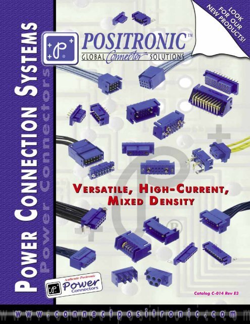
Catalog C-014 Rev E3
POSITRONIC INDUSTRIESAbout UsFounded in 1966, Positronic Industries is a vertically integrated manufacturer of high quality interconnect products.Positronic has earned the worldwide reputation as a service oriented, quick-reaction, top quality connector supplier. Weare committed to maintaining this reputation by continuous implementation of our Complete Capability concept.Complete CapabilityDesign & Development• Designs new connectors and modifies existing connectors to meet industry requirements• Continuously conducts marketing studies to identify industry needs for new products• Ongoing interest in unique connector designsToolingMachining• Tooling support for all manufacturing areas within company• Provides 80% of new tooling, punch press dies, molds, jigs and fixtures used at Positronic factory locations worldwideMachining• Automatic screw machines produce finely crafted contacts and hardware for connector bodies• Trained technicians operate machines from Tornos, Bechler and Brown & SharpeMolding• Molds all plastic connector components such as insulators, hoods, angle brackets and more• Overmold capability availablePlating• Applies gold and other metal finishes to connector components to any required thicknessMolding• Plating conforms to all military specificationsQuality Assurance Lab• Quality assurance system certified to ISO 9001• Maintains aggressive TQM program• Able to test to IEC, EIA, UL, MIL-DTL-24308, MIL-DTL-28748, SAE AS 39029 and MIL-C-85049 requirementsFinished Stock Inventory• Each main factory location maintains a large inventory of connector components and accessories• Same day shipments available on many standard connector products• Stocking agreements available for qualified customersWorldwide Sales & Service• Responsive attitude toward customer needs• Fully trained sales staff located worldwideFinished Stock Inventory• Facilities located in USA, France, India, Puerto Rico, and Singapore.Products described within this catalog may beprotected by one or more of the following US. patents:#4,900,261 #5,255,580 #5,329,697#6,260,268 #6,835,079 #7,115,002Patented in Canada, 1992Other Patents PendingUnless otherwise specified, dimensional tolerances are:1) ±0.001 inches [0.03 mm] for male contact mating diameters.2) ±0.003 inches [0.08 mm] for contact termination diameters.3) ±0.005 inches [0.13 mm] for all other diameters.4) ±0.015 inches [0.38 mm] for all other dimensions.Information in this catalog is proprietary to Positronic and its subsidiaries. Positronic believes the data contained herein to be reliable. Since thetechnical information is given free of charge, the user employs such information at his own discretion and risk. Positronic Industries assumes noresponsibility for results obtained or damages incurred from use of such information in whole or in part.Positronic Industries’ FEDERAL SUPPLY CODE (Cage Code) FOR MANUFACTURERS is 28198
P O S I T R O N I C I N D U S T R I E SProven PerformanceNEW!In 1989, Positronic Introduced the <strong>Power</strong><strong>Connection</strong> <strong>Systems</strong> series. Since that timePCS has been the power connector of choicein a wide variety of applications. Thepopularity of PCS is due to a growing list offeatures, they include:**Low Contact Resistance****Sequential Mating Options****Discriminating Locking System****Board to Board / Board -Cable / Cable - Cable****Size 12 Contacts withScrew Terminations****Safety Shrouded Options****Many Connector VariantsAvailable From Stock****Mixed Density Variants**NEW!RoHSCompliant• per EU Directive 2002/95/EC•RoHS Compliantoptions available!DIMENSIONS ARE IN INCHES [MILLIMETERS].ALL DIMENSIONS ARE SUBJECT TO CHANGE.i
GENERAL INFORMATION PCS SERIES SAFETY SHROUD POWER INPUTPositronic Industriesconnectpositronic.comTABLE OF CONTENTSG E N E R A L I N F O R M A T I O N<strong>Power</strong><strong>Connection</strong><strong>Systems</strong>Typical <strong>Connection</strong> <strong>Systems</strong> .............................................................................................................. 1-3Demystifying Current Ratings ............................................................................................................ 4Large Surface Area Contact Mating System ..................................................................................... 5Compliant Terminations...................................................................................................................... 6P C S S E R I E SCustomer Specified Arrangements .................................................................................................... 7Technical Information ......................................................................................................................... 8Temperature Rise Curves .................................................................................................................. 9Mating Dimensions............................................................................................................................. 10Straight Solder Printed Board Connectors......................................................................................... 11-12Compliant Press-Fit <strong>Power</strong> Connectors ............................................................................................. 13Straight Solder And Compliant Contact Hole Pattern........................................................................ 14-15Right Angle (90°) Solder Printed Board Connectors ......................................................................... 16-17Right Angle (90°) Press-Fit Connectors............................................................................................. 18Right Angle (90°) Printed Board Contact Hole Pattern...................................................................... 19-20Panel Mount Connectors with Solder Cup Contacts.......................................................................... NEW!20Cable Connectors with Removable Contacts..................................................................................... 21-22Panel Mount Connectors with Removable Contacts.......................................................................... 23-24Sequential Mating System ................................................................................................................. 25Ordering Information .......................................................................................................................... 26S A F E T Y S H R O U D S E R I E STechnical Information ......................................................................................................................... 27Connector <strong>Systems</strong> and Cable Connector......................................................................................... 28Panel Mount Connector ..................................................................................................................... 29Straight Solder and Right Angle (90°) Solder Printed Board Mount Connector ................................ 30Ordering Information .......................................................................................................................... 31P O W E R I N P U T S E R I E STechnical Information ......................................................................................................................... 32<strong>Connection</strong> <strong>Systems</strong> and Temperature Rises Curves ....................................................................... 33Cable and Panel Mount Connector.................................................................................................... 34Straight Solder Printed Board Mount,Compliant Press-Fit Connector, and Contact Hole Pattern ............................................................... 35Right Angle (90°) Printed Board Mount Connector and Contact Hole Pattern.................................. 36Screw Termination and Sequential Mating Contacts ......................................................................... 37Ordering Information .......................................................................................................................... 38iiDIMENSIONS ARE IN INCHES [MILLIMETERS].ALL DIMENSIONS ARE SUBJECT TO CHANGE.
<strong>Power</strong><strong>Connection</strong><strong>Systems</strong>TABLE OF CONTENTSPositronic Industriesconnectpositronic.comP C S M I X E D D E N S I T Y S E R I E STechnical Information ......................................................................................................................... 39-40Temperature Rises Curves................................................................................................................. 40Cable Connector ................................................................................................................................ 41NEW!Panel Mount Connector ..................................................................................................................... 42Straight Printed Board Mount Connector and Contact Hole Pattern ................................................. 43Right Angle (90°) Printed Board Mount Connector and Contact Hole Pattern.................................. 44Compliant Press-Fit Connector.......................................................................................................... 45Ordering Information .......................................................................................................................... 46R E M O V A B L E C O N T A C TRemovable Contact Technical Information......................................................................................... 47Removable Contact Technical Information and Removable Crimp Signal Contact Size 20 .............. 48Removable Crimp Contact and Solder Cup Contact Size 16 ............................................................ 49Removable Shielded Contact Size 16 and Removable Crimp Contact Size 12................................ 50Removable Solder Cup Contact Size 12 and Removable Crimp Contact Size 8.............................. NEW! 51Removable Solder Cup and Removable High Voltage Contact Size 8.............................................. 52Removable Shielded Contact Size 8.................................................................................................. 53A P P L I C A T I O N T O O L SCrimping Information for Removable Crimp Contacts ....................................................................... 54-55Soldering and Crimping Information for Shielded Contacts............................................................... 56Contact Crimp Tools and Accessories ............................................................................................... 57Contact Application Tools Cross Reference List ................................................................................ NEW!58-59Press-Fit User Information and Connector Installation Tooling.......................................................... 60Compliant Press-fit Connectors Printed Board Hole Sizes................................................................ 61PCS MIXED DENSITYREMOVABLE CONTACTAPPLICATION TOOLSA C C E S S O R I E SRight Angle (90°) Metal and Plastic Mounting Brackets .................................................................... 62Push-on Fasteners and Mounting Screws ......................................................................................... 63Connector Hoods ............................................................................................................................... 64Quick Release Mounting Clip and Panel Cutout................................................................................ NEW!65Fixed Style Mounting Clip and Panel Cutout ..................................................................................... 66Panel Mount Cutout ........................................................................................................................... 67Blind Mating System and Panel Cutout ............................................................................................. 68ACCESSORIESDIMENSIONS ARE IN INCHES [MILLIMETERS].ALL DIMENSIONS ARE SUBJECT TO CHANGE.iii
POSITRONIC CABLIZED CONNECTORSSAVE TIME AND MONEY! Let Positronic support yourconnector requirements by cablizing your <strong>Power</strong> connectorselection. Positronic offers technical support andmanufacturing capability for cablized connectors. Contactyour factory direct sales representative for details!Quality AssuranceEngineering ManagementDesign and Testing ServicePositronic Industries’ Engineering Department:1. Works closely with customers.Springfield Cable AssemblyPuerto Rico Cable Assembly2. Prepares component and cablized connectorsystems, hardware design, and performancespecifications.3. Designs each system in accordance withapplicable customer, domestic, and internationalstandards.4. Defines and directs required performance andverification testing.Connectors Designed To Customer SpecificationsPositronic connectors can be modified to customers specifications.Examples: select loading of contacts for cost savings or to gain creepage andclearance distances; longer PCB terminations; customer specified hardware.Positronic can develop and tool new connector designswith reasonable price and delivery.Contact Technical Sales with your particular requirements.ivDIMENSIONS ARE IN INCHES [MILLIMETERS].ALL DIMENSIONS ARE SUBJECT TO CHANGE.
<strong>Power</strong><strong>Connection</strong><strong>Systems</strong>SYSTEM 1MOTHER BOARD-DAUGHTER BOARDPRINTED BOARD TO PRINTEDBOARD CONNECTION SYSTEMSPLB06M300A1 Straight solder orPLB06M92ST20A1 Complianttermination press-fitPositronic Industriesconnectpositronic.comGENERAL INFORMATIONPLB06F4BN0A1PLB06M4BN0A2SYSTEM 2SIDE TO SIDEBOARD MOUNTINGPLB06F300A1 Straightsolder orPLB06F94ST40A1Compliant terminationpress-fitPLB06F4BN0C1PLB06M4BN0C1SYSTEM 3STACKABLEBOARD MOUNTINGPLB06F42BN0C1SYSTEM 4SANDWICHBOARD MOUNTINGPLB06F32N0C1PLB06M300A1 Straightsolder or PLB06M93ST30A1Compliant termination press-fitPLB06F3N0C1PLB06F300A1 Straightsolder or PLB06F93ST30A1Compliant termination press-fit1
GENERAL INFORMATIONPositronic Industriesconnectpositronic.comSYSTEM 5CABLE TO RIGHT ANGLE(90°) BOARD MOUNTINGCABLECONNECTION SYSTEMSPLB06F4BN0A1PLB06M0000With contacts installed<strong>Power</strong><strong>Connection</strong><strong>Systems</strong>Crimp or solder terminationPLB06F0000With contacts installedPLB06M4BN0A2Crimp or solder terminationLock holeLock tabTypical for connectionsystems 5, 6, 7 and 8SYSTEM 6CABLE TO STRAIGHTBOARD MOUNTINGPLB06F300C1 Straight solder orPLB06F92ST20C1 Complianttermination press-fitPLB06M0000With contacts installedCrimp or solderterminationPLB06M300C1 Straight solder orPLB06M92ST20C1 Complianttermination press-fitPLB06F0000With contacts installedSYSTEM 7CABLE TO CABLECrimp or solder terminationPLB06F0000With contacts installedPLB06M0000With contacts installedCrimp or solder termination2
<strong>Power</strong><strong>Connection</strong><strong>Systems</strong>SYSTEM 8PANEL MOUNTED TO CABLECABLE AND INTEGRALFEED THROUGH CONNECTION SYSTEMSPLB06F206A1Mounting clipPANEL MOUNT AND CABLE ADAPTERSPositronic Industriesconnectpositronic.comSYSTEM 9CABLE CONNECTORWITH CABLE ADAPTERGENERAL INFORMATIONPLB06F0050Non-removable fixedcontacts with 18 AWG[1.0mm 2 ] solder wireterminations or crimpcontact terminations forwire sizes 12 AWG[4.0mm 2 ] through 32AWG [0.03mm 2 ]PLB06M0000With contactsinstalledCrimp or solderterminationINTEGRAL FEED THROUGH CONNECTION SYSTEMALLOWS THREE WAY INTERFACE• PCB FRONTSIDE TO A CONNECTOR• PCB BACKSIDE TO A CONNECTOR• PRESS-FIT CONNECTIONS WITH PCBFRONTSIDECONNECTORINTERFACESOLID FEEDTHROUGH CONTACTHAS A PRESS-FIT ZONE TOINTERFACE TO PCBCONTACT TECHNICALSALES FOR MOREINFORMATION.BACKSIDECONNECTORINTERFACEDIMENSIONS ARE IN INCHES [MILLIMETERS].ALL DIMENSIONS ARE SUBJECT TO CHANGE.3
GENERAL INFORMATIONPositronic Industriesconnectpositronic.comDEMYSTIFYING CURRENT RATINGS<strong>Power</strong><strong>Connection</strong><strong>Systems</strong>Connector current ratings seem to be shrouded in mystery at times. The user wonders how a listed current ratingis relevant to a particular application. Perhaps more mysterious is how similar connectors from various manufacturerslist different current rating values. While it is true that material choices and design can enhance a connector’s currentrating, the test method by which the rating was developed must be understood when evaluations are made.Users of connectors for power applications are entitled to current rating test details in order to make an informedchoice. Ideally, a connector’s current rating should be developed within the application for which it is being considered.Although ideal, this approach is not always practical given the many differing applications. In order for connector manufacturersto give potential product users an idea of what can be expected, connectors are given current ratings basedon a specific test method.A wide variety of test methods are employed in order to develop current ratings for connectors. Some of thesemethods come from standards that are recognized industry-wide, while others are unique to the manufacturer or user.These various test methods can produce different results for the same product. It is no wonder confusion sometimesresults.There are key factors that, when understood, can help in choosing the right power connector. All test methods usedto rate current have similarities; however, there are variables in applying the test methods which explain differingresults.Current ratings are usually established by first developing a temperature rise curve. This curve plots temperaturerise against increasing current levels. The curve is a reliable tool in understanding heat generation of the connector atvarious currents. When a defined failure is reached, the test ends. The highest current level achieved is usually listedas the current rating.The temperature rise curve, and therefore the current rating, will change when certain key factors are varied.These are:●DEMYSTIFYINGCURRENT RATINGSWhere is the temperature sensing probe placed? If placed on the contact in the matingarea (the hottest spot), the results will be quite different than if placed on the outside of theconnector body.●Are the contacts being tested and rated in free air or are they contained within theconnector housing? Contacts will obviously be cooler in free air.●Are all of the contacts in the connector under load? If only part of the contactsare under load, the temperature rise could be less.●What is the defined failure? Does the test end when the temperature rise reaches 30°C, 40°C,or some other number? Does it end when the temperature rise plus ambient temperatureequal the operating limit of the connector housing? The current rating will be fixed by thedefined failure point.●How were the test samples prepared? Were the samples energized through a P.C. board?How many layers? How large were the traces? What was the weight of the copper? Werethe samples energized through wire? What size was the wire? How long was the wire? Wasthe sample tested in static or forced air conditions? All of these factors can affect coolingcharacteristics.Clearly, a current rating value alone is not enough, and must be viewed in the context of the test used to developthe rating. When the test method is understood, evaluating and comparing power connectors for specific applicationsbecomes much less of a mystery.4DIMENSIONS ARE IN INCHES [MILLIMETERS].ALL DIMENSIONS ARE SUBJECT TO CHANGE.
<strong>Power</strong><strong>Connection</strong><strong>Systems</strong>THE PCS SERIES utilizes Positronic Industries’LARGE SURFACE AREA CONTACT MATING SYSTEM●●●●●LARGE SURFACE AREACONTACT MATING SYSTEMSeparates mechanical and electrical functions for superior performanceLow contact resistance provides minimized voltage drop across the contact“Closed Entry” design prevents damage to female contacts and will not allowmisaligned or bent contacts to enterPrecision machined from solid, high conductivity copper alloyUniform insertion/withdrawal forces through repeated mating cyclesPositronic Industriesconnectpositronic.comGENERAL INFORMATIONWHY IS THE L.S.A. SYSTEM SUPERIOR?The primary function of connector contact is electricalconductivity. Also, a mechanical function is required toprovide normal force between male and female contacts.In order to provide for proper mechanical characteristics,material that has good memory or “springiness” mustbe chosen. This will ensure contact normal force in a coupledcondition and allow for repeated coupling and uncoupling.Unfortunately, many materials that have good memorycharacteristics have low electrical conductivity. Forinstance, beryllium copper is a good choice for mechanicalfunction; however, some beryllium copper alloys are poorconductors and have relatively low conductivity rates.The conductivity path of many contact designsgoes directly through materials that have been chosenbased on mechanical need. If these materials havea low conductivity rating, increased contact resistance willresult.Positronic Industries Large Surface Area ContactSystem separates the mechanical and electrical functions.A spring retention member provides normal forces,while the electrical conductivity path is through highlyconductive contact material. See above detail.DIMENSIONS ARE IN INCHES [MILLIMETERS].ALL DIMENSIONS ARE SUBJECT TO CHANGE.5
GENERAL INFORMATIONPositronic Industriesconnectpositronic.comCOMPLIANT TERMINATIONSReliable, solderless connections from connectors tobackplanes started with solid press-fit technology.Although these are still used today, concerns about boarddamage led to the use of compliant press-fit technology.This technology allows the connection to be made throughcompliance of the contact termination along with P.C.board hole deformation. Although risk of damaged P.C.boards and backplanes is lessened, damage can still<strong>Power</strong><strong>Connection</strong><strong>Systems</strong>POSITRONIC INDUSTRIES’ BI-SPRING POWERPRESS-FIT TERMINATIONSThe Next Evolution In Compliant Technology. Fully Compliant, Fully Reliable.occur due to relatively high insertion and extraction forces.The next step in press-fit technology is a highly reliableconnection between the contact termination andbackplane that is accomplished with reduced insertionand extraction forces. This eliminates risk of P.C. boardand backplane damage. This technology exists todaywith Positronic Industries Bi-Spring <strong>Power</strong> Press-Fit termination.Bi-Spring <strong>Power</strong>Press-Fit CompliantTerminations●●●Average insertion and extraction forces of size 16 contacts are 22N [5 lbs.] percontact and do not produce stresses in P.C. boards and backplanes that can occurwith higher insertion forces. These stresses can cause board warpage and holedamage.Connector systems utilizing Bi-Spring terminations use mounting screws to securethe connector to the P.C. board or backplane. Stresses that occur during coupling,uncoupling or shock and vibration of systems are not transferred to the P.C. boards orbackplanes through the press-fit connection. The electrical integrity of the connectorto board interface is maintained; this is particularly important in power applications.Bellcore GR1217 details a preference for mounting hardware when using press-fit terminations.Size 16 Bi-Spring terminations are designed to meet the performance requirementsand hole diameters as listed in the internationally recognized specificationIEC60352-5.●Lower insertion and extraction forces eliminate the need for expensive pressing equipment.COMPLIANT TERMINATION PRESS-FIT CONNECTOR0.155 [3.94]dp. x ø0.076 [1.93]mounting holetyp.Polarizing grooveFixed member ordiscriminatinglocking systemAB#2 self tapping mounting screwsSteel, zinc plate or stainless steel, passivatedContact lead-in diameter 0.047 [1.19]Contact termination diameter 0.069 [1.76]6DIMENSIONS ARE IN INCHES [MILLIMETERS].ALL DIMENSIONS ARE SUBJECT TO CHANGE.
<strong>Power</strong><strong>Connection</strong><strong>Systems</strong>CUSTOMER SPECIFIEDARRANGEMENTSPositronic Industriesconnectpositronic.comThe design of <strong>Power</strong> <strong>Connection</strong> <strong>Systems</strong> Series connectors allows for the development of application specificcontact arrangements in a timely manner and at a reasonable price. Thirteen connector housing sizes exist that mayaccommodate size 20, size 16, size 12, or size 8 contacts (see the <strong>Power</strong> <strong>Connection</strong> <strong>Systems</strong> catalog for connectorhousing dimensions). After reviewing the dimensions and the following basic information, contact Technical Sales withyour current, voltage, and safety requirements. We look forward to working with you to develop a connector for yourspecific needs.BASIC CONNECTOR DIMENSIONSMale Connector DimensionsPART NUMBERAFemale Connector DimensionsA±0.020 [0.51]0.408[10.36]PLA03**00A1PLAH03**00A1PLA04**00A1PLAH04**00A1PLA06**00A1PLAH06**00A1PLA08**00A1PLAH08**00A1PART NUMBER1.126[28.60]1.324[33.63]1.718[43.64]2.112[53.64]A0.408[10.36]A±0.020 [0.51]PCS SERIESA±0.020 [0.51]0.606[15.39]NEW!PLB06**00A1PLBH06**00A1PLB08**00A1PLBH08**00A1PLB12**00A1PLBH12**00A1PLB16**00A1PLBH16**00A1PLB20**00A1PLBH20**00A11.126[28.60]1.324[33.63]1.718[43.64]2.112[53.64]2.506[63.65]0.606[15.39]A±0.020 [0.51]PART NUMBERAA±0.020 [0.51]0.802[20.37]PLC09**00A1PLCH09**00A1PLC12**00A1PLCH12**00A1PLC18**00A1PLCH18**00A1PLC24**00A1PLCH24**00A1PLC30**00A1PLCH30**00A11.126[28.60]1.324[33.63]1.718[43.64]2.112[53.64]2.506[63.65]0.802[20.37]A±0.020 [0.51]Four Contact Sizes to Choose FromNEW!Size 8 contactØ0.142 [3.61]Ø0.094 [2.39]Many Termination Types Can Be SuppliedStraight Solder or Press-FitRight Angle (90°) SolderCrimp RemovableRemovable Solder CupSize 12 contactØ0.062 [1.57]Popular OptionsSequential MatingSelective LoadingSize 16 contactNEW!Size 20 contactØ0.040 [1.00]Contact sizes and termination types may bemixed within a single connector.DIMENSIONS ARE IN INCHES [MILLIMETERS].ALL DIMENSIONS ARE SUBJECT TO CHANGE.7
P O S I T R O N I C I N D U S T R I E SPositronic Industriesconnectpositronic.comTECHNICAL INFORMATION<strong>Power</strong><strong>Connection</strong><strong>Systems</strong>TECHNICAL CHARACTERISTICSPCS SERIESMATERIALS AND FINISHES:Insulator:Glass-filled polyester, UL 94V-0.Contact technical sales for availability ofhigh temperature insulator material.Contacts:Precision machined copper alloy with goldflash over nickel, or 0.000030 inch [0.76µ]gold over nickel, or 0.000050 [1.27µ] goldover nickel. Solder coated terminationsoptional.Mounting Clip:Beryllium copper with nickel plate.Hood:Glass filled polyester, UL 94V-0.Mounting Bracket:Brass with tin plate.Push-on Fastener:Spring tempered copper alloy, tin plateELECTRICAL CHARACTERISTICS:CONTACT CURRENT RATING:Standard Contact Material:High ConductivityContact Material:INITIAL CONTACT RESISTANCE:See page 9 for detail information.See page 9 for detail information.Standard Contact Material: 0.0016 ohms max. per IEC 512-2, Test 2b.High ConductivityContact Material: 0.0007 ohms max. per IEC 512-2, Test 2b.Insulation Resistance: 5 G ohms per IEC 512-2, Test 3a, Method A.Voltage Proof: 2000 V rms per IEC 512-2, Test 4a, Method C.Creepage Distance:0.157 inch [4 mm] minimum.Clearance Distance:0.125 inch [3.2 mm] minimum.Working Voltage:Designed to meet UL 600 VAC andCSA 600 VAC.Working Temperature:-55°C to +125°CContact technical sales for availability ofhigh temperature insulator material.ELECTRICAL CHARACTERISTICS OF COMPLIANTPRESS-FIT CONNECTION TO PLATED-THROUGH-HOLEOF PRINTED BOARD:0.064 inch [1.63mm] diameter hole of a0.125 inch [3.2mm] thick printed boardInitial Contact Resistanceof <strong>Connection</strong>: Less than 1.0 milliohms per IEC 512-2,Test 2a.Change in ContactResistance of <strong>Connection</strong>After Mechanical, Electricalor Climactic Conditioning:Gas Tight <strong>Connection</strong>sTest:SHIELDED CONTACT TECHNICALCHARACTERISTICS:See page 47.RoHSCompliant• per EU Directive 2002/95/EC•Less than 0.5 milliohms increase per IEC512-2, Test 2a.Less than 0.2 milliohms increase incontact resistance after 1 hour per EIA 364,TP36, Method One.For RoHS optionssee page 26.MECHANICAL CHARACTERISTICS:Removable Contacts:Insert contact to rear face of insulator,release from front face of insulator. Size16, 0.062 inch [1.57 mm] diameter malecontact. Female contact “closed entry”design for highest reliability.Removable Contact Retentionin Insulator: 15 lbs. [67N] per IEC 512-8, Test 15a.Fixed Contacts:Solder cup and printed board terminations.Size 16, 0.062 inch [1.57 mm] diametermale contact. Female contact has “closedentry” design for highest reliability.Fixed Contact Retentionin Insulator:6 lbs. [26N].Resistance to SolderIron Heat:Contact Terminations:Contact Insertion andWithdrawal Forces:<strong>Connection</strong> <strong>Systems</strong>:Sequential Mating System:500˚F [260°C] for 10 seconds duration perIEC 512-6, Test 12e, 25 watt soldering iron.Crimp or solder removable contacts from wiresizes 12 AWG [4.0 mm 2 ] through 24 AWG[0.25 mm 2 ]. Straight and Right Angle (90°)solder printed board mount, 0.062 inch [1.57mm] tail diameter. Compliant terminationpress-fit. Fixed contact solder cup termination,18 AWG [1.0 mm 2 ] maximum.8 oz. [2.2N] nominal per contact.Connector provides cable to cable, cable toprinted board, cable to panel mount andprinted board to printed board application.Cable and printed board mount connectors.Male contacts provide as many as three matinglengths.Locking System:Insulators provide locking between cable tocable, cable to printed board and cable topanel mount applications.Polarizations:Provided in insulator design. Further polarizationin cable connectors can be providedby mixing male contacts in female insulatorsand female contacts in male insulators.Mounting to Printed Board: Rapid installation push-on fasteners.Self-tapping screws for compliant connectors.Mechanical Operations: 500 operations per IEC 512-5.MECHANICAL CHARACTERISTICS OF COMPLIANTPRESS-FIT CONNECTORS:Press-Fit Contact Bi-SpringConstruction, CompliantTermination: 0.0695 inch [1.77mm] diameter with 0.050inch [1.27mm] lead-in diameter. Offeredwith two termination lengths.Contact Retention inInsulator and 0.125 inch[3.2mm] thick printed board:Vibration:Initial Press-In Forceof Individual Contactinto Plated-Through-Hole:Initial Push-Out Force ofIndividual Contact intoPlated-Through-Hole:5 lbs. [22N] minimum combined retentionforces per MIL-STD-2166, Type IIIcompliant contact classification, after thirdrepair- replacement of contact in insulatorand plated-through-hole, 0.064 inch[1.63mm] diameter in a 0.125 inch[3.2mm] thick printed board.No electrical discontinuity of 1µ second orgreater when tested per MIL-STD-1344,Method 2005, Test conditioning.10 lbs. [44N] average when pushed into a0.064 inch [1.63mm] Ø hole in a 0.125inch [3.2mm] thick printed board.8.5 lbs. [38N] average when pushed out ofan 0.064 inch [1.63mm] Ø hole in a 0.125inch [3.2mm] thick printed board.8DIMENSIONS ARE IN INCHES [MILLIMETERS].ALL DIMENSIONS ARE SUBJECT TO CHANGE.U.L. Recognized*File #E49351CSA RecognizedFile #LR54219*Note: U.L. Recognized all sizes, except PLB20, consult TechnicalSales for status.
<strong>Power</strong><strong>Connection</strong><strong>Systems</strong>TEMPERATURE RISE CURVETEMPERATURE RISE CURVEPositronic Industriesconnectpositronic.comRATED CURRENT (AMPS)48444036322824201612STANDARD CONTACT MATERIALSCONNECTORS WITH PL* PREFIX8400 10 20 30 40 50 60 70 80 90 100TEMPERATURE RISE (°C)PLA03PLB12PLC30RATED CURRENT (AMPS)HIGH CONDUCTIVITY CONTACT MATERIALSCONNECTORS WITH PL*H PREFIXOR “S” SUFFIX ON CRIMP CONTACTS48444036322824201612840010 20 30 40 50 60 70 80 90 100TEMPERATURE RISE (°C)PLAH03PLBH12PLCH30Updatedthis chartwith highconductivityinformationPCS SERIESTEST DETAIL: Each curve was developed using individual connector bodies fully loaded with contacts. All powercontacts energized through 12 awg wire. Temperature rise was measured in the contact mating area. Test wasconducted with connectors in static air. Terminations of test connectors were straight compliant press-fit to right angle(90°) solder. See page 4 for more information.CONTACT CURRENT RATINGSCONNECTORVARIANTSTANDARDCONTACTSCONNECTORVARIANTHIGHCONDUCTIVITYCONTACTSPLA03 32 amps PLAH03 42 ampsPLB12 25 amps PLBH12 32 ampsPLC30 18 amps PLCH30 24 ampTemperature rise curves and contact current ratings were developed for the specific connector variants shownwhen tested in accordance with UL1977.This information is provided so that the user can make comparisons between various connector sizes andcontact materials.C-014 Rev E3DIMENSIONS ARE IN INCHES [MILLIMETERS].ALL DIMENSIONS ARE SUBJECT TO CHANGE.9
Positronic Industriesconnectpositronic.comMATING DIMENSIONS<strong>Power</strong><strong>Connection</strong><strong>Systems</strong>MATING DIMENSIONS(FULLY MATED)0.830 [21.08]0.830 [21.08] 0.830 [21.08] 0.830 [21.08]Straight Board Mount Maleto Straight Board MountFemaleStraight Board Mount Maleto Right Angle (90°) BoardMount FemaleRight Angle (90°) BoardMount Male to StraightBoard Mount FemaleRight Angle (90°) BoardMount Male to Right Angle(90°) Board Mount FemalePCS SERIES0.790 [20.07] 0.790 [20.07]0.790 [20.07]Straight Board Mount Maleto Panel MountFemalePanel Mount Maleto Straight BoardMount FemaleRight Angle (90°) BoardMount Male to PanelBoard Mount Female0.790 [20.07]0.750[19.05]Panel Mount Maleto Right Angle (90°) BoardMount FemalePanel Mount Maleto Panel MountFemale1.100 [27.94]1.150 [29.21] 1.110 [27.94] 1.150 [29.21]Cable Mount Maleto Straight BoardMount FemaleStraight Board MountMale to CableMount FemaleCable Mount Maleto Right Angle (90°)Board Mount FemaleRight Angle (90°) Board MountMale to Cable MountFemale1.060 [26.92]1.110 [28.19]1.420 [36.07]10Cable Mount MaletoPanel Mount FemalePanel Mount Maleto Cable MountFemaleCable Mount MaletoCable Mount Female
<strong>Power</strong><strong>Connection</strong><strong>Systems</strong>STRAIGHT SOLDER PRINTEDBOARD CONNECTORPositronic Industriesconnectpositronic.comA±0.020 [0.51]PLA STRAIGHT PRINTED BOARD MOUNT CONNECTORSCODE 3, 0.146 [3.71] CONTACT EXTENSIONMALE0.600[15.24]0.146 [3.71]0.146 [3.71]0.600[15.24]FEMALEA±0.020 [0.51]Typical part number:PLA03M300A1PLAH03M300A10.408[10.36]ø0.062 [1.57]ø0.062 [1.57]0.230 [5.84]0.408[10.36]Typical part number:PLA03F300A1PLAH03F300A1*Asterisk determinesgender of connector,M for male,F for female.PLB STRAIGHT PRINTED BOARD MOUNT CONNECTORSCODE 3, 0.146 [3.71] CONTACT EXTENSIONMALEPART NUMBER A PART NUMBER APLA03*300A1PLAH03*300A1PLA04*300A1PLAH04*300A11.126[28.60]1.324[33.63]PLA06*300A1PLAH06*300A1PLA08*300A1PLAH08*300A11.718[43.64]2.112[53.64]Plating- See ordering informationfor contact plating options.For connection systems 1, 4 and 6.FEMALE0.6000.600[15.24][15.24]A±0.020 [0.51]0.146 [3.71]0.146 [3.71]A±0.020 [0.51]PCS SERIESTypical part number:PLB06M300A1PLBH06M300A1*Asterisk determinesgender of connector,M for male,F for female.0.606[15.39]ø0.062 [1.57]ø0.062 [1.57]PART NUMBER A PART NUMBER APLB06*300A1PLBH06*300A1PLB08*300A1PLBH08*300A1PLB12*300A1PLBH12*300A11.126[28.60]1.324[33.63]1.718[43.64]PLB16*300A1PLBH16*300A1PLB20*300A1PLBH20*300A12.112[53.64]2.506[63.65]0.230 [5.84]NEW!0.606[15.39]Typical part number:PLB06F300A1PLAH06F300AIPlating- See ordering informationfor contact plating options.For connection systems 1, 4 and 6.PLC STRAIGHT PRINTED BOARD MOUNT CONNECTORSCODE 3, 0.146 [3.71] CONTACT EXTENSIONFEMALEMALE0.600[15.24]0.600[15.24]A±0.020 [0.51]0.146 [3.71]0.146 [3.71]A±0.020 [0.51]0.802[20.37]ø0.062 [1.57]ø0.062 [1.57]0.802[20.37]Typical part number:PLC09M300A1PLCH09M300A1*Asterisk determinesgender of connector,M for male,F for female.PART NUMBER A PART NUMBER APLC09*300A1PLCH09*300A1PLC12*300A1PLCH12*300A1PLC18*300A1PLCH18*300A11.126[28.60]1.324[33.63]1.718[43.64]PLC24*300A1PLCH24*300A1PLC30*300A1PLCH30*300A12.112[53.64]2.506[63.65]0.230 [5.84]Typical part number:PLC09F300A1PLCH09F300A1Plating- See ordering informationfor contact plating options.For connection systems 1, 4 and 6.DIMENSIONS ARE IN INCHES [MILLIMETERS].ALL DIMENSIONS ARE SUBJECT TO CHANGE.11
Positronic Industriesconnectpositronic.comSTRAIGHT SOLDER PRINTEDBOARD CONNECTOR<strong>Power</strong><strong>Connection</strong><strong>Systems</strong>A±0.020 [0.51]PLA STRAIGHT PRINTED BOARD MOUNT CONNECTORSCODE 32, 0.377 [9.58] CONTACT EXTENSIONMALE0.600[15.24]0.377 [9.58] 0.377 [9.58]0.600[15.24]FEMALEA±0.020 [0.51]Typical part number:PLA03M3200A1PLAH03M3200A10.408[10.36]ø0.062 [1.57]ø0.062 [1.57]0.230 [5.84]0.408[10.36]Typical part number:PLA03F3200A1PLAH03F3200A1PCS SERIES*Asterisk determinesgender of connector,M for male,F for female.PART NUMBER A PART NUMBER APLA03*3200A1PLAH03*3200A1PLA04*3200A1PLAH04*3200A11.126[28.60]1.324[33.63PLA06*3200A1PLAH06*3200A1PLA08*3200A1PLAH08*3200A11.718[43.64]2.112[53.64]PLB STRAIGHT PRINTED BOARD MOUNT CONNECTORSCODE 32, 0.377 [9.58] CONTACT EXTENSIONPlating- See ordering informationfor contact plating options.For connection systems 1, 3, 4 and 6.MALEFEMALE0.600[15.24]0.600[15.24]A±0.020 [0.51] 0.377 [9.58] 0.377 [9.58]A±0.020 [0.51]Typical part number:PLB06M3200A1PLBH06M3200A1*Asterisk determinesgender of connector,M for male,F for female.0.606[15.39]ø0.062 [1.57]ø0.062 [1.57]PART NUMBER A PART NUMBER APLB06*3200A1PLBH06*3200A1PLB08*3200A1PLBH08*3200A1PLB12*3200A1PLBH12*3200A11.126[28.60]1.324[33.63]1.718[43.64]PLB16*3200A1PLBH16*3200A1PLB20*3200A1PLBH20*3200A12.112[53.64]2.506[63.65]NEW!0.230 [5.84]0.606[15.39]Typical part number:PLB06F3200A1PLBH06F3200A1Plating- See ordering informationfor contact plating options.For connection systems 1, 3, 4 and 6.PLC STRAIGHT PRINTED BOARD MOUNT CONNECTORSMALECODE 32, 0.377 [9.58] CONTACT EXTENSIONFEMALE0.600[15.24]0.600[15.24]A±0.020 [0.51] 0.377 [9.58] 0.377 [9.58]A±0.020 [0.51]0.802[20.37]ø0.062 [1.57]ø0.062 [1.57]0.802[20.37]Typical part number:PLC09M3200A1PLCH09M3200A10.230 [5.84]Typical part number:PLC09F3200A1PLCH09F3200A112*Asterisk determinesPLC09*3200A1gender of connector, PLCH09*3200A1M for male,PLC12*3200A1F for female. PLCH12*3200A1PLC18*3200A1PLCH18*3200A1DIMENSIONS ARE IN INCHES [MILLIMETERS].ALL DIMENSIONS ARE SUBJECT TO CHANGE.PART NUMBER A PART NUMBER A1.126[28.60]1.324[33.63]1.718[43.64]PLC24*3200A1PLCH24*3200A1PLC30*3200A1PLCH30*3200A12.112[53.64]2.506[63.65]Plating- See ordering informationfor contact plating options.For connection systems 1, 3, 4 and 6.
<strong>Power</strong><strong>Connection</strong><strong>Systems</strong>A±0.020 [0.51]Typical part number:PLA03M93ST30A1PLAH03M93ST30A1**Asterisks determinegender of connector,M for male,F for female andcontact code 92 or 93.MALE0.408[10.36]MALEPLA COMPLIANT PRESS-FIT CONNECTORSCODE 92 OR CODE 93FEMALE0.600[15.24]PARTNUMBERPLA03**00A1PLAH03**00A1PLA04**00A1PLAH04**00A1PLA06**00A1PLAH06**00A1PLA08**00A1PLAH08**00A1A1.126[28.60]1.324[33.63]1.718[43.64]2.112[53.64]COMPLIANT PRESS-FITCONNECTORPositronic Industriesconnectpositronic.com0.600[15.24]L LA±0.020 [0.51]See page 60for Installation Tooling.Plating- See ordering information forcontact plating options.For connection systems 1,4 and 6.* MOUNTING SCREWS CAN BE SUP-PLIED WITH CONNECTORS USINGSTEP 5 IN ORDERING INFORMATIONON PAGE 26. MOUNTING SCREWSCAN ALSO BE ORDERED SEPARATELYBY PART NUMBER. SEE PAGE 63.0.408[10.36]0.6000.600[15.24][15.24]A±0.020 [0.51] LLA±0.020 [0.51]0.230[5.84]CONTACTCODEPLB COMPLIANT PRESS-FIT CONNECTORSCODE 92 OR CODE 93FEMALE9293Typical part number:PLA03F93ST30A1PLAH03F93ST30A1PCB SCREWLTHICKNESS CODE *0.183[4.65]0.218[5.54]0.093[2.36]0.125[3.18]ST2SS2ST3SS3ST4SS4NEW!GENERAL INFORMATIONPCS SERIES0.606[15.39]0.606[15.39]Typical part number:PLB06M93ST30A1PLBH06M93ST30A1**Asterisks determinegender of connector,M for male,F for female andcontact code 92 or 93.NEW!PARTNUMBERPLB06**00A1PLBH06**00A1PLB08**00A1PLBH08**00A1PLB12**00A1PLBH12**00A1PLB16**00A1PLBH16**00A1PLB20**00A1PLBH20**00A1A1.126[28.60]1.324[33.63]1.718[43.64]2.112[53.64]2.506[63.65]See page 60for Installation Tooling.Plating- See ordering information forcontact plating options.For connection systems 1,4 and 6.* MOUNTING SCREWS CAN BE SUP-PLIED WITH CONNECTORS USINGSTEP 5 IN ORDERING INFORMATIONON PAGE 26. MOUNTING SCREWSCAN ALSO BE ORDERED SEPARATELYBY PART NUMBER. SEE PAGE 63.0.230[5.84]CONTACTCODE9293L0.183[4.65]0.218[5.54]Typical part number:PLB06F93ST30A1PLBH06F93ST30A1PCBTHICKNESS0.093[2.36]0.125[3.18]SCREWCODE *ST2SS2ST3SS3ST4SS4NEW!MALEPLC COMPLIANT PRESS-FIT CONNECTORSCODE 92 OR CODE 93FEMALE0.600[15.24]0.600[15.24]A±0.020 [0.51] LLA±0.020 [0.51]0.802[20.37]0.802[20.37]Typical part number:PLC09M93ST30A1PLCH09M93ST30A1**Asterisks determinegender of connector,M for male,F for female andcontact code 92 or 93.PARTNUMBERPLC09**00A1PLCH09**00A1PLC12**00A1PLCH12**00A1PLC18**00A1PLCH18**00A1PLC24**00A1PLCH24**00A1PLC30**00A1PLCH30**00A1A1.126[28.60]1.324[33.63]1.718[43.64]2.112[53.64]2.506[63.65]See page 60for Installation Tooling.Plating- See ordering information forcontact plating options.For connection systems 1,4 and 6.* MOUNTING SCREWS CAN BE SUP-PLIED WITH CONNECTORS USINGSTEP 5 IN ORDERING INFORMATIONON PAGE 26. MOUNTING SCREWSCAN ALSO BE ORDERED SEPARATELYBY PART NUMBER. SEE PAGE 63.0.230[5.84]CONTACTCODE9293L0.183[4.65]0.218[5.54]Typical part number:PLC09F93ST30A1PLCH09F93ST30A1PCBTHICKNESS0.093[2.36]0.125[3.18]SCREWCODE *ST2SS2ST3SS3ST4SS4NEW!C-014 Rev E3DIMENSIONS ARE IN INCHES [MILLIMETERS].ALL DIMENSIONS ARE SUBJECT TO CHANGE.13
Positronic Industriesconnectpositronic.comSTRAIGHT SOLDER AND COMPLIANTCONTACT HOLE PATTERN<strong>Power</strong><strong>Connection</strong><strong>Systems</strong>0.441±0.002[11.20±0.05]0.882±0.005[22.40±0.13]0.197±0.002[5.00±0.05]TYP.0.540±0.002[13.72±0.05]1.080±0.005[27.43±0.13]0.197±0.002[5.00±0.05]0.099±0.002[2.51±0.05]TYP.PLA 03PLA 04PCS SERIES0.737±0.002[18.72±0.05]1.474±0.005[37.44±0.13]PLA 060.197±0.002[5.00±0.05]0.099±0.002[2.51±0.05]TYP.0.934±0.002[23.72±0.05]1.868±0.005[47.45±0.13]PLA 080.197±0.002[5.00±0.05]0.099±0.002[2.51±0.05]TYP.0.441±0.002[11.20±0.05]0.882±0.005[22.40±0.13]0.197±0.002[5.00±0.05]TYP.0.540±0.002[13.72±0.05]1.080±0.005[27.43±0.13]0.197±0.002[5.00±0.05]0.099±0.002[2.51±0.05]TYP.0.099±0.002[2.51±0.05]0.197±0.002[5.00±0.05]PLB 060.099±0.002[2.51±0.05]0.197±0.002[5.00±0.05]PLB 080.737±0.002[18.72±0.05]1.474±0.005[37.44±0.13]0.197±0.002[5.00±0.05]0.099±0.002[2.51±0.05]TYP.0.934±0.002[23.72±0.05]1.868±0.005[47.45±0.13]0.197±0.002[5.00±0.05]0.099±0.002[2.51±0.05]TYP.0.099±0.002[2.51±0.05]0.197±0.002[5.00±0.05]PLB 120.099±0.002[2.51±0.05]0.197±0.002[5.00±0.05]PLB 16NEW!0.099±0.002[2.51±0.05]0.197±0.002[5.00±0.05]1.131±0.002[28.73±0.05]2.262±0.005[57.45±0.13]PLB 200.197±0.002[5.00±0.05]0.099±0.002[2.51±0.05]TYP.SUGGESTED PRINTED BOARD HOLE SIZES:Suggest 0.080 [2.03] Ø holes in printed board for solder contacttermination positions.Suggest 0.100 [2.54] Ø holes in printed board when mountingconnectors with # 2 thread forming screws.Suggest 0.123±0.003 [3.15±0.08] Ø holes in printed board whenmounting connector with push-on fasteners.NOTE: See page 61 for suggested printed board drill hole sizes,recommended plating and finished hole sizes for compliantcontact termination positions.14DIMENSIONS ARE IN INCHES [MILLIMETERS].ALL DIMENSIONS ARE SUBJECT TO CHANGE.
<strong>Power</strong><strong>Connection</strong><strong>Systems</strong>STRAIGHT SOLDER AND COMPLIANTCONTACT HOLE PATTERNPositronic Industriesconnectpositronic.com0.441±0.002[11.20±0.05]0.882±0.005[22.40±0.13]0.197±0.002[5.00±0.05]TYP.0.540±0.002[13.72±0.05]1.080±0.005[27.43±0.13]0.197±0.002[5.00±0.05]0.099±0.002[2.51±0.05]TYP.0.394±0.002[10.01±0.05]0.394±0.002[10.01±0.05]0.197±0.002[5.00±0.05]PLC 09 0.197±0.002 PLC 12[5.00±0.05]0.737±0.002[18.72±0.05]0.394±0.002[10.01±0.05]0.197±0.002[5.00±0.05]1.474±0.005[37.44±0.13]0.197±0.002[5.00±0.05]0.099±0.002[2.51±0.05]TYP.0.934±0.002[23.72±0.05]0.394±0.002[10.01±0.05]1.868±0.005[47.45±0.13]PLC 18 0.197±0.002PLC 24[5.00±0.05]0.197±0.002[5.00±0.05]0.099±0.002[2.51±0.05]TYP.PCS SERIES0.394±0.002[10.01±0.05]0.197±0.002[5.00±0.05]1.131±0.002[28.73±0.05]2.262±0.005[57.45±0.13]PLC 300.197±0.002[5.00±0.05]0.099±0.002[2.51±0.05]TYP.SUGGESTED PRINTED BOARD HOLE SIZES:Suggest 0.080 [2.03] Ø holes in printed board for solder contacttermination positions.Suggest 0.100 [2.54] Ø holes in printed board when mountingconnectors with # 2 thread forming screws.Suggest 0.123±0.003 [3.15±0.08] Ø holes in printed board whenmounting connector with push-on fasteners.NOTE: See page 61 for suggested printed board drill hole sizes,recommended plating and finished hole sizes for compliant contacttermination positions.Connectors Designed To Customer SpecificationsPositronic connectors can be modified to customers specifications.Examples: select loading of contacts for cost savings or to gain creepage andclearance distances; longer PCB terminations; customer specified hardware.Positronic can develop and tool new connector designswith reasonable price and delivery.Contact Technical Sales with your particular requirements.DIMENSIONS ARE IN INCHES [MILLIMETERS].ALL DIMENSIONS ARE SUBJECT TO CHANGE.15
Positronic Industriesconnectpositronic.comRIGHT ANGLE (90°) SOLDER PRINTEDBOARD CONNECTORPLA RIGHT ANGLE (90°) PRINTED BOARD MOUNTCODE 4, 0.146 [3.71] CONTACT EXTENSION<strong>Power</strong><strong>Connection</strong><strong>Systems</strong>0.408[10.36]0.146 [3.71]0.600[15.24]A±0.020 [0.51] 0.098 [2.49]0.098 [2.49]A±0.020 [0.51]Typical part number:PLA03M4BN0A1PLAH03M4BN0A1MALEø0.062 [1.57]ø0.062 [1.57]0.600[15.24]0.146 [3.71]FEMALE0.408[10.36]Typical part number:PLA03F4BN0A1PLAH03F4BN0A1PCS SERIES*Asterisk determinesgender of connector,M for male,F for female.A±0.020 [0.51]MALEPART NUMBER A PART NUMBER APLA03*400A1PLAH03*400A1PLA04*400A1PLAH04*400A1PLB RIGHT ANGLE (90°) PRINTED BOARD MOUNTCODE 4, 0.146 [3.71] CONTACT EXTENSION0.600[15.24]1.126[28.60]1.324[33.630.098 [2.49]PLA06*400A1PLAH06*400A1PLA08*400A1PLAH08*400A10.098 [2.49]0.197 [5.00] 0.197 [5.00]1.718[43.64]2.112[53.64]0.600[15.24]Plating- See ordering information forcontact plating options.For connection systems 1, 2 and 5.FEMALEA±0.020 [0.51]Typical part number:PLB06M4BN0A1PLBH06B4BN0A10.606[15.39]*Asterisk determinesgender of connector,M for male,F for female.0.146 [3.71]ø0.062 [1.57]ø0.062 [1.57]PART NUMBER A PART NUMBER APLB06*400A1PLBH06*400A1PLB08*400A1PLBH08*400A1PLB12*400A1PLBH12*400A11.126[28.60]1.324[33.63]1.718[43.64]PLB16*400A1PLBH16*400A1PLB20*400A1PLBH20*400A12.112[53.64]2.506[63.65]NEW!0.146 [3.71]0.606[15.39]Typical part number:PLB06F4BN0A1PLBH06F4BN0A1Plating- See ordering information forcontact plating options.For connection systems 1, 2 and 5.A±0.020 [0.51]MALEPLC RIGHT ANGLE (90°) PRINTED BOARD MOUNTCODE 4, 0.146 [3.71] CONTACT EXTENSION0.600[15.24]0.197 [5.00]0.098 [2.49]0.197 [5.00]0.197 [5.00]0.098 [2.49]0.197 [5.00]0.600[15.24]FEMALEA±0.020 [0.51]0.802[20.37]0.802[20.37]Typical part number:PLC09M4BN0A1PLCH09M4BN0A1*Asterisk determinesgender of connector,M for male,F for female.0.146 [3.71]ø0.062 [1.57]ø0.062 [1.57]PART NUMBER A PART NUMBER APLC09*400A1PLCH09*400A1PLC12*400A1PLCH12*400A1PLC18*400A1PLCH18*400A11.126[28.60]1.324[33.63]1.718[43.64]PLC24*400A1PLCH24*400A1PLC30*400A1PLCH30*400A12.112[53.64]2.506[63.65]0.146 [3.71]Typical part number:PLC09F4BN0A1PLCH09F4BN0A1Plating- See ordering information forcontact plating options.For connection systems 1, 2 and 5.16DIMENSIONS ARE IN INCHES [MILLIMETERS].ALL DIMENSIONS ARE SUBJECT TO CHANGE.
<strong>Power</strong><strong>Connection</strong><strong>Systems</strong>RIGHT ANGLE (90°) SOLDER PRINTEDBOARD CONNECTORPositronic Industriesconnectpositronic.comA±0.020 [0.51]PLA RIGHT ANGLE (90°) PRINTED BOARD MOUNTCODE 42, 0.377 [9.58] CONTACT EXTENSIONMALEFEMALE0.408[10.36]0.600[15.24]0.098 [2.49]0.098 [2.49]0.600[15.24]0.408[10.36]A±0.020 [0.51]0.377 [9.58]0.377 [9.58]Typical part number:PLA03M42BN0A1PLAH03M42BN0A1*Asterisk determinesgender of connector,M for male,F for female.A±0.020 [0.51]MALE0.600[15.24]ø0.062 [1.57]0.197 [5.00]0.098 [2.49]ø0.062 [1.57]PART NUMBER A PART NUMBER APLA03*4200A1PLAH03*4200A1PLA04*4200A1PLAH04*4200A11.126[28.60]1.324[33.63]PLA06*4200A1PLAH06*4200A1PLA08*4200A1PLAH08*4200A11.718[43.64]2.112[53.64]PLB RIGHT ANGLE (90°) PRINTED BOARD MOUNTCODE 42, 0.377 [9.58] CONTACT EXTENSION0.197 [5.00]0.098 [2.49]0.600[15.24]Typical part number:PLA03F42BN0A1PLAH03F42BN0A1Plating- See ordering information forcontact plating options.For connection systems 1,2,3 and 5.FEMALEA±0.020 [0.51]PCS SERIES0.606[15.39]0.606[15.39]0.377 [9.58]0.377 [9.58]Typical part number:PLB06M42BN0A1PLBH06M42BN0A1*Asterisk determinesgender of connector,M for male,F for female.ø0.062 [1.57]ø0.062 [1.57]PART NUMBER A PART NUMBER APLB06*4200A1PLBH06*4200A1PLB08*4200A1PLBH08*4200A1PLB12*4200A1PLBH12*4200A11.126[28.60]1.324[33.63]1.718[43.64]PLB16*4200A1PLBH16*4200A1PLB20*4200A1PLBH20*4200A12.112[53.64]2.506[63.65]NEW!Typical part number:PLB06F42BN0A1PLBH06F42BN0A1Plating- See ordering information forcontact plating options.For connection systems 1,2,3 and 5.A±0.020 [0.51]PLC RIGHT ANGLE (90°) PRINTED BOARD MOUNTCODE 42, 0.377 [9.58] CONTACT EXTENSIONMALEFEMALE0.802[20.37]0.600[15.24]0.197 [5.00]0.098 [2.49]0.197 [5.00]0.197 [5.00]0.098 [2.49]0.197 [5.00]0.600[15.24]0.802[20.37]A±0.020 [0.51]0.377 [9.58]0.377 [9.58]Typical part number:PLC09M42BN0A1PLCH09M42BN0A1*Asterisk determinesgender of connector,M for male,F for female.ø0.062 [1.57]ø0.062 [1.57]PART NUMBER A PART NUMBER APLC09*4200A1PLCH09*4200A1PLC12*4200A1PLCH12*4200A1PLC18*4200A1PLCH18*4200A11.126[28.60]1.324[33.63]1.718[43.64]PLC24*4200A1PLCH24*4200A1PLC30*4200A1PLCH30*4200A12.112[53.64]2.506[63.65]Typical part number:PLC09F42BN0A1PLCH09F42BN0A1Plating- See ordering information forcontact plating options.For connection systems 1,2,3 and 5.DIMENSIONS ARE IN INCHES [MILLIMETERS].ALL DIMENSIONS ARE SUBJECT TO CHANGE.17
Positronic Industriesconnectpositronic.comRIGHT ANGLE (90°) PRESS-FIT CONNECTORFOR USE WITH “FLAT ROCK” TOOLING<strong>Power</strong><strong>Connection</strong><strong>Systems</strong>PCS SERIESA±0.020 [0.51]Typical part number:PLA03M63B30A1PLAH03M63B30A1A±0.020 [0.51]PLA RIGHT ANGLE (90°) PRESS-FIT CONNECTORCODE 62 OR CODE 63MALEFor connection systems 1,2 and 5.FEMALE0.408[10.36]0.606[15.39]L0.560[14.22]PART NUMBER A PART NUMBER APLA03**B30A1PLAH03**B30A1PLA04**B30A1PLAH04**B30A11.126[28.60]1.324[33.63]0.560[14.22]0.138 [3.51] 0.138 [3.51]Plating- See orderinginformation forcontact platingoptions.**Asterisk determines gender of connector, M for male, F for female, and contact code 62 or 63.MALEPLA06**B30A1PLAH06**B30A1PLA08**B30A1PLAH08**B30A11.718[43.64]2.112[53.64]0.560[14.22]PLB RIGHT ANGLE (90°) PRESS-FIT CONNECTORCODE 62 OR CODE 63For connection systems 1,2 and 5.Plating- See orderinginformation forcontact platingoptions.CONNECTORS AREDESIGNED TO BEMOUNTED TO THE PCBWITH SCREWS, SEESCREW CODE.0.560[14.22]0.408[10.36]0.606[15.39]A±0.020 [0.51]LTypical part number:PLA03F63B30A1 PLAH03F63B30A1CONTACTCODE6263L0.183[4.65]0.219[5.56]FEMALEPCBTHICKNESS0.093[2.36]0.125[3.18]A±0.020 [0.51]SCREWP/N *Mountingscrews areorderedseparately.See page63.Typical part number:PLB06M63B30A1PLBH06M63B30A1L0.138 [3.51]0.197 [5.00]PART NUMBER A PART NUMBER APLB06**B30A1PLBH06**B30A1PLB08**B30A1PLBH08**B30A11.126[28.60]1.324[33.63]PLB12**B30A1PLBH12**B30A1PLB16**B30A1PLBH16**B30A11.718[43.64]2.112[53.64]CONNECTORS AREDESIGNED TO BEMOUNTED TO THE PCBWITH SCREWS, SEESCREW CODE.**Asterisk determines gender of connector, M for male, F for female, and contact code 62 or 63.L0.138 [3.51]0.197 [5.00]CONTACTCODE6263L0.183[4.65]0.219[5.56]Typical part number:PLB06F63B30A1PLBH06F63B30A1PCBTHICKNESS SCREWP/N *0.093[2.36]0.125[3.18]Mountingscrews areorderedseparately.See page63.PLC RIGHT ANGLE (90°) PRESS-FIT CONNECTORCODE 62 OR CODE 63MALEFor connection systems 1,2 and 5.FEMALEA±0.020 [0.51]0.560[14.22]Plating- See orderinginformation forcontact platingoptions.0.560[14.22]A±0.020 [0.51]0.802[20.37]0.802[20.37]LLTypical part number:PLC09M63B30A1PLCH09M63B30A10.138 [3.51]0.197 [5.00]0.197 [5.00]0.138 [3.51]0.197 [5.00]0.197 [5.00]Typical part number:PLC09F63B30A1PLCH09F63B30A118PART NUMBER A PART NUMBER APLC09**B30A1PLCH09**B30A1PLC12**B30A1PLCH12**B30A1PLC18**B30A1PLCH18**B30A11.126[28.60]1.324[33.63]1.718[43.64]PLC24**B30A1PLCH24**B30A1PLC30**B30A1PLCH30**B30A112.112[53.64]2.506[63.65]CONNECTORS AREDESIGNED TO BEMOUNTED TO THE PCBWITH SCREWS, SEESCREW CODE.**Asterisk determines gender of connector, M for male, F for female, and contact code 62 or 63.CONTACTCODE6263L0.183[4.65]0.219[5.56]PCBTHICKNESS SCREWP/N *0.093[2.36]0.125[3.18]Mountingscrews areorderedseparately.See page63.C-014 Rev E3
<strong>Power</strong><strong>Connection</strong><strong>Systems</strong>RIGHT ANGLE (90°) PRINTED BOARDCONTACT HOLE PATTERNPositronic Industriesconnectpositronic.com0.441±0.002[11.20±0.05]0.882±0.005[22.40±0.13]0.197±0.002[5.00±0.05]TYP.0.540±0.002[13.72±0.05]1.080±0.005[27.43±0.13]0.197±0.002[5.00±0.05]0.099±0.002[2.51±0.05]TYP.0.237±0.015[6.02±0.38]PLA 030.237±0.015[6.02±0.38]PLA 040.737±0.002[18.72±0.05]0.237±0.015[6.02±0.38]1.474±0.005[37.44±0.13]PLA 060.197±0.002[5.00±0.05]0.099±0.002[2.51±0.05]TYP.0.934±0.002[23.72±0.05]0.237±0.015[6.02±0.38]1.868±0.005[47.45±0.13]PLA 080.197±0.002[5.00±0.05]0.099±0.002[2.51±0.05]TYP.PCS SERIES0.441±0.002[11.20±0.05]0.882±0.005[22.40±0.13]0.197±0.002[5.00±0.05]TYP.0.540±0.002[13.72±0.05]1.080±0.005[27.43±0.13]0.197±0.002[5.00±0.05]0.099±0.002[2.51±0.05]TYP.0.040±0.015[1.02±0.38]0.237±0.015[6.02±0.38]PLB 060.040±0.015[1.02±0.38]0.237±0.015[6.02±0.38]PLB 080.737±0.002[18.72±0.05]1.474±0.005[37.44±0.13]0.197±0.002[5.00±0.05]0.099±0.002[2.51±0.05]TYP.0.934±0.002[23.72±0.05]1.868±0.005[47.45±0.13]0.197±0.002[5.00±0.05]0.099±0.002[2.51±0.05]TYP.0.040±0.015[1.02±0.38]0.197±0.015[5.00±0.38]PLB 120.040±0.015[1.02±0.38]0.237±0.015[6.02±0.38]PLB 16NEW!1.131±0.002[28.73±0.05]2.262±0.005[57.45±0.13]0.197±0.002[5.00±0.05]0.099±0.002[2.51±0.05]TYP.0.441±0.002[11.20±0.05]0.882±0.005[22.40±0.13]0.197±0.002[5.00±0.05]TYP.0.040±0.015[1.02±0.38]0.237±0.015[6.02±0.38]PLB 200.157±0.015[3.99±0.38]0.040±0.015[1.02±0.38]0.237±0.015[6.02±0.38]PLC 09See page 20 for suggested printed board hole sizes.DIMENSIONS ARE IN INCHES [MILLIMETERS].ALL DIMENSIONS ARE SUBJECT TO CHANGE.19
Positronic Industriesconnectpositronic.comRIGHT ANGLE (90°) PRINTED BOARD CONTACTHOLE PATTERN AND PANEL MOUNT CONNECTORWITH SOLDER CUP CONTACTS<strong>Power</strong><strong>Connection</strong><strong>Systems</strong>0.540±0.002[13.72±0.05]1.080±0.005[27.43±0.13]0.197±0.002[5.00±0.05]0.099±0.002[2.51±0.05]TYP.0.737±0.002[18.72±0.05]1.474±0.005[37.44±0.13]0.197±0.002[5.00±0.05]0.099±0.002[2.51±0.05]TYP.0.157±0.002[3.99±0.05]0.040±0.002[1.02±0.05]0.237±0.002[6.02±0.05]PLC 120.157±0.002[3.99±0.05]0.040±0.002[1.02±0.05]0.237±0.002[6.02±0.05]PLC 18PCS SERIES0.934±0.002[23.72±0.05]1.868±0.005[47.45±0.13]0.197±0.002[5.00±0.05]0.099±0.002[2.51±0.05]TYP.1.131±0.002[28.73±0.05]2.262±0.005[57.45±0.13]0.197±0.002[5.00±0.05]0.099±0.002[2.51±0.05]TYP.0.157±0.002[3.99±0.05]0.040±0.002[1.02±0.05]0.237±0.002[6.02±0.05]PLC 240.157±0.002[3.99±0.05]0.040±0.002[1.02±0.05]0.237±0.002[6.02±0.05]PLC 30SUGGESTED PRINTED BOARD HOLE SIZES:Suggest 0.080 [2.03] Ø holes in printed board for solder contact termination positions.Suggest 0.123±0.003 [3.15±0.08] Ø holes in printed board when mounting connector with push-on fasteners.NOTE: See page 61 for suggested printed board drill hole sizes, recommended plating and finished hole sizesfor compliant contact termination positions.200.600[15.24]B0.200[5.08]NEW!MALEA±0.020 [0.51]PANEL MOUNT CONNECTORS WITH SOLDER CUP CONTACTS18 AWG max.[1.0 mm 2]TYPICAL PART NUMBER:PLB06M200A1DIMENSIONS ARE IN INCHES [MILLIMETERS].ALL DIMENSIONS ARE SUBJECT TO CHANGE.For connection system 8.CODE 2, 18 AWG [1.00mm 2 ] MAX.18 AWG max.[1.0 mm 2]FEMALEA±0.020 [0.51]0.600[15.24]TYPICAL PART NUMBER:PLB06F200A1B0.200[5.08]NEW!CONNECTORVARIANTSPLA03PLA04PLA06PLA08PLB06PLB08PLB12PLB16PLB20PLC09PLC12PLC18PLC24PLC30A1.126[28.60]1.324[33.63]1.718[43.64]2.112[53.64]1.126[28.60]1.324[33.63]1.718[43.64]2.112[53.64]2.506[63.65]1.126[28.60]1.324[33.63]1.718[43.64]2.112[53.64]2.506[63.65]B0.408[10.36]0.408[10.36]0.408[10.36]0.408[10.36]0.606[15.39]0.606[15.39]0.606[15.39]0.606[15.39]0.606[15.39]0.802[30.37]0.802[30.37]0.802[30.37]0.802[30.37]0.802[30.37]
<strong>Power</strong><strong>Connection</strong><strong>Systems</strong>MALE INSULATOR DIMENSIONSFOR CABLE CONNECTORSPositronic Industriesconnectpositronic.comMALE INSULATOR DIMENSIONSFOR CABLE CONNECTORS WITH SIZE 16 REMOVABLE CONTACTSCODE 0 OR CODE 7CONTACTS ARE NOT SUPPLIED WITH CONNECTOR AND MUST BE ORDERED SEPARATELY0.500 [12.70]0.870±0.020[22.10±0.51]12345 67 80.986±0.020[25.04±0.51]1.184±0.020[30.07±0.51]1.578±0.020[40.08±0.51]1.972±0.020[50.09±0.51]PCS SERIES1230.408±0.015[10.36±0.38]0.408±0.015[10.36±0.38]0.408±0.015[10.36±0.38]1 2 3 4 1 2 34 5 6 1 2 3 4 5 6 7 80.408±0.015[10.36±0.38]PLA 03 PLA 04 PLA 06 PLA 080.986±0.020[25.04±0.51]1.184±0.020[30.07±0.51]1.578±0.020[40.08±0.51]1.972±0.020[50.09±0.51]1425360.606±0.015[15.39±0.38]1 23 40.606±0.015[15.39±0.38]1 2 34 5 60.606±0.015[15.39±0.38]1 2 3 45 6 7 85 6 7 8 7 8 910 11 129 10 11 12 13 14 15 160.606±0.015[15.39±0.38]PLB 06PLB 08PLB 12PLB 160.986±0.020[25.04±0.51]1.184±0.020[30.07±0.51]1.578±0.020[40.08±0.51]1.972±0.020[50.09±0.51]14 5 67 8 9230.802±0.015[20.37±0.38]12340.802±0.015[20.37±0.38]1 234 5 60.802±0.015[20.37±0.38]1 2 3 455 67 8 7 8 9 10 11 129 10 11 12 13 14 15 169 1011 1213 14 1516 17 1817 18 19 20 21 22 23 246780.802±0.015[20.37±0.38]PLC 09 PLC 12 PLC 18PLC 24For information regardingsize 16 removable contacts,see Removable Contact section,pages 47-53.1 2 3 4 5 6 711 12 13 14 1521 22 23 24 252.366±0.020[60.10±0.51]1626PLC 3017278 9 1018 19 2028 29 300.802±0.015[20.37±0.38]DIMENSIONS ARE IN INCHES [MILLIMETERS].ALL DIMENSIONS ARE SUBJECT TO CHANGE.21
Positronic Industriesconnectpositronic.comFEMALE INSULATOR DIMENSIONSFOR CABLE CONNECTORS<strong>Power</strong><strong>Connection</strong><strong>Systems</strong>FEMALE INSULATOR DIMENSIONSFOR CABLE CONNECTORS WITH SIZE 16 REMOVABLE CONTACTSCODE 0 OR CODE 7CONTACTS ARE NOT SUPPLIED WITH CONNECTOR AND MUST BE ORDERED SEPARATELY0.550 [13.97]0.920±0.020[23.37±0.51]4 3 218 7 6 5PCS SERIES0.876±0.020[22.25±0.51]1.074±0.020[27.28±0.51]1.468±0.020[37.29±0.51]1.862±0.020[47.29±0.51]32 1 0.408±0.015[10.36±0.38]4 3 2 10.408±0.015[10.36±0.38]6 5 4 3 2 10.408±0.015[10.36±0.38]8 7 6 5 4 3 2 10.408±0.015[10.36±0.38]PLA 03 PLA 04 PLA 06 PLA 080.876±0.020[22.25±0.51]1.074±0.020[27.28±0.51]1.468±0.020[37.29±0.51]1.862±0.020[47.29±0.51]3 216 5 40.606±0.015[15.39±0.38]438 7216 50.606±0.015[15.39±0.38]6 5 43 2 112 11 109 8 70.606±0.015[15.39±0.38]8 7 6 5 4 3 2 116 15 14 1312 11 10 90.606±0.015[15.39±0.38]PLB 06PLB 08PLB 12PLB 160.876±0.020[22.25±0.51]1.074±0.020[27.28±0.51]1.468±0.020[37.29±0.51]1.862±0.020[47.29±0.51]3692581470.802±0.015[20.37±0.38]4 32 18 76 512 110.802±0.015[20.37±0.38]6 5 43 2 112 11 109 8 710 918 17 1615 14 130.802±0.015[20.37±0.38]8 716 1524 236 54 3 2 114 1312 11 10 922 2120 19 18 170.802±0.015[20.37±0.38]PLC 09PLC 12 PLC 18PLC 242.256±0.020[57.30±0.51]10 9 8 7 6 5 4 3 2 120 19 18 17 1615 14 13 12 1130 29 28 27 26 25 24 23 22 21PLC 300.802±0.015[20.37±0.38]For information regardingsize 16 removable contacts,see Removable Contact section,pages 47-53.22DIMENSIONS ARE IN INCHES [MILLIMETERS].ALL DIMENSIONS ARE SUBJECT TO CHANGE.
<strong>Power</strong><strong>Connection</strong><strong>Systems</strong>MALE INSULATOR DIMENSIONSFOR PANEL MOUNT CONNECTORSPositronic Industriesconnectpositronic.comMALE INSULATOR DIMENSIONSFOR PANEL MOUNT CONNECTORS WITH SIZE 16 REMOVABLE CONTACTSCODE 1 OR CODE 8CONTACTS ARE NOT SUPPLIED WITH CONNECTOR AND MUST BE ORDERED SEPARATELY0.190±0.020[4.83±0.51]0.560±0.020[14.22±0.51]0.870±0.020[22.10±0.51]12 341.126±0.020[28.60±0.51]1.324±0.020[33.63±0.51]5 67 81.718±0.020[43.64±0.51]2.112±0.020[53.64±0.51]PCS SERIES0.408±0.015[10.36±0.38]0.408±0.015[10.36±0.38]0.408±0.015[10.36±0.38]1 2 3 1 2 3 4 1 2 3 4 5 6 1 2 3 45 6 7 80.408±0.015[10.36±0.38]PLA 03 PLA 04 PLA 06 PLA 081.126±0.020[28.60±0.51]1.324±0.020[33.63±0.51]1.718±0.020[43.64±0.51]2.112±0.020[53.64±0.51]1 2 345 60.606±0.015[15.39±0.38]1 2 35 67480.606±0.015[15.39±0.38]1 2 34 5 61 27 891011120.606±0.015[15.39±0.38]9103114125136147158160.606±0.015[15.39±0.38]PLB 06PLB 08PLB 12PLB 161.126±0.020[28.60±0.51]1.324±0.020[33.63±0.51]1.718±0.020[43.64±0.51]2.112±0.020[53.64±0.51]1 2 34 5 67 8 90.802±0.015[20.37±0.38]1 2 3 45 67 89 1011 120.802±0.015[20.37±0.38]1 2 34 5 67 8 9 10 11 1213 14 15 16 17 180.802±0.015[20.37±0.38]1 2 3 45 6 7 89 10 11 12 13 14 15 1617 18 19 20 21 22 23 240.802±0.015[20.37±0.38]PLC 09 PLC 12 PLC 18PLC 242.506±0.020[63.65±0.51]For informationregarding panelcutouts, seepage 67.1 2 3 411 12 13 1421 22 23 245 6 7 8 915 162526PLC 3017 18 1927 28 291020300.802±0.015[20.37±0.38]For information regardingsize 16 removable contacts,see Removable Contact section,pages 47-53.DIMENSIONS ARE IN INCHES [MILLIMETERS].ALL DIMENSIONS ARE SUBJECT TO CHANGE.23
Positronic Industriesconnectpositronic.comFEMALE INSULATOR DIMENSIONSFOR PANEL MOUNT CONNECTORS<strong>Power</strong><strong>Connection</strong><strong>Systems</strong>FEMALE INSULATOR DIMENSIONSFOR PANEL MOUNT CONNECTORS WITH SIZE 16 REMOVABLE CONTACTSCODE 1 OR CODE 8CONTACTS ARE NOT SUPPLIED WITH CONNECTOR AND MUST BE ORDERED SEPARATELY0.190±0.020[4.83±0.51]0.560±0.020[14.22±0.51]0.920±0.020[23.37±0.51]PCS SERIES1.126±0.020[28.60±0.51]1.324±0.020[33.63±0.51]4 38 726151.718±0.020[43.64±0.51]2.112±0.020[53.64±0.51]0.408±0.015[10.36±0.38]0.408±0.015[10.36±0.38]0.408±0.015[10.36±0.38]3 214 3 2 1 6 5 4 3 2 18 7 6 54 3 2 10.408±0.015[10.36±0.38]PLA 03 PLA 04 PLA 06 PLA 081.126±0.020[28.60±0.51]1.324±0.020[33.63±0.51]1.718±0.020[43.64±0.51]2.112±0.020[53.64±0.51]3 216 5 40.606±0.015[15.39±0.38]483726150.606±0.015[15.39±0.38]6 5 412 11 103928170.606±0.015[15.39±0.38]8 7 6 54 3 2 116 15 14 13 12 11 10 90.606±0.015[15.39±0.38]PLB 06PLB 08PLB 12PLB 161.126±0.020[28.60±0.51]1.324±0.020[33.63±0.51]1.718±0.020[43.64±0.51]2.112±0.020[53.64±0.51]3 216 5 49 8 70.802±0.015[20.37±0.38]4 3 2 18 7 6 50.802±0.015[20.37±0.38]6 5 43 2 112 11 109 8 712 11 10 9 18 17 161514 130.802±0.015[20.37±0.38]8 716 1524 23614225132141220311192101819170.802±0.015[20.37±0.38]PLC 09 PLC 12 PLC 18PLC 242.506±0.020[63.65±0.51]For informationregarding panelcutouts, seepage 67.10 9 8 7 620 19 18 17 1630 29 28 27 2651525PLC 30414243 2 113 12 1123 22 210.802±0.015[20.37±0.38]For information regardingsize 16 removable contacts,see Removable Contact section,pages 47-53.24DIMENSIONS ARE IN INCHES [MILLIMETERS].ALL DIMENSIONS ARE SUBJECT TO CHANGE.
<strong>Power</strong><strong>Connection</strong><strong>Systems</strong>SEQUENTIAL CONTACTMATING CONNECTORPositronic Industriesconnectpositronic.comSEQUENTIAL MATING SYSTEM*REMOVABLE CONTACTS FOR CABLE CONNECTORS MUST BE ORDERED SEPARATELYFOR CONTACT SELECTION, SEE SIZE 16 CONTACTS ON PAGE 49EXAMPLE 1 EXAMPLE 21 2 3 4 5 6 1 2 3 4 5 6 7 8"X"LENGTHCODE“X”CONTACT LENGTHA 0.370 [9.40]B 0.330 [8.38]C 0.310 [7.87]D 0.290 [7.37]E 0.250 [6.35]POSITIONNUMBER"X"Typical Part Number:PLA06M300A1-E1B2BMATINGCONNECTOR TYPE CONTACTOPTIONSBoard to BoardBoard to Cable*Cable to Cable*B, D, EA, C, EA, DTypical Part Number:PLA08M4B0C1-D8BPCS SERIESWIRE SIZEAWG/[mm 2 ]12 - 14[4.0 - 2.5]16 - 18 - 20[1.5 - 1.0 - 0.5]LENGTHCODE “A”SEQUENTIAL MATING SYSTEMCRIMP REMOVABLE CONTACT PART NUMBERSLENGTHCODE “C”LENGTHCODE “D”LENGTHCODE “E”MC112N-133.3 MC112N-133.2 MC112N-133.1 MC112N-133.0MC116N-133.3 MC116N-133.2 MC116N-133.1 MC116N-133.0For information regardingsize 16 removable contacts,see Removable Contact section,pages 47-53.SELECTION GUIDE FOR ORDERING DIFFERENT CONTACT LENGTHSSTEP 9 OF ORDERING INFORMATIONSELECT CONNECTOR USING ORDERING INFORMATION ON PAGE 26THEN CHOOSE STEPS BELOW FOR SEQUENTIAL MATING SYSTEM CONTACTSSTEPEXAMPLESTEP 1Specify code for most frequentlyused contact mating length. Thislength is used for all contacts notspecified in steps 2 through 9.STEP 2Position number for first speciallength contact.STEP 3Length of contact specified in step 2.(Choose from length code chart)STEP 4Position number for second speciallength contact.1 2 3 4 5 6 7 8 9E 1 B 2 B 3 D 4 DSTEP 9Length of contact specified in step 8(Choose from length code chart).STEP 8Position number for fourth special lengthcontact.STEP 7Length of contact specified in step 6 (Choosefrom length code chart).STEP 6Position number for third special length contact.STEP 5Length of contact specified in step 4 (Choose fromlength code chart).DIMENSIONS ARE IN INCHES [MILLIMETERS].ALL DIMENSIONS ARE SUBJECT TO CHANGE.25
P O S I T R O N I C I N D U S T R I E SPositronic Industriesconnectpositronic.comPCS SERIES CONNECTORORDERING INFORMATION<strong>Power</strong><strong>Connection</strong><strong>Systems</strong>PCS SERIESSTEP 1 - BASIC SERIESPLA - 1 RowPLAH - 1 Row High conductivity contactsPLB - 2 RowPLBH - 2 Row High conductivity contactsPLC - 3 RowPLCH - 3 Row High conductivity contactsSTEP 2 - CONNECTOR VARIANTS1 Row - 03, 04, 06, 082 Row - 06, 08, 12, 16, **203 Row - 09, 12, 18, 24, 30STEP 3 - CONNECTOR GENDERM - MaleF - FemaleSTEP 5 - MOUNTING STYLE0 - None,B - Metal Right Angle (90°) Mounting Bracket.BN - Metal Right Angle (90°) Mounting Bracket with Push-on Fastener.B3 - Plastic Right Angle (90°) Mounting Bracket with Cross Bar.B3N - Plastic Right Angle (90°) Mounting Bracket with Cross Bar and Push-onFastener.N - Push-On Fastener For Straight Printed Board Mount ConnectorsST2 - Self-tapping steel screws 2-28 x 0.250±0.030 [6.35±0.76] length for 0.093[2.36] thick board. Use with contact code 62, 63, 92 or 93.ST3 - Self-tapping steel screws 2-28 x 0.312±0.030 [7.92±0.76] length for 0.125[3.18] thick board. Use with contact code 62, 63, 92 or 93.ST4 - Self-tapping steel screws 2-28 x 0.375±0.030 [9.53±0.76] length for 0.175[4.45] thick board. Use with contact code 62, 63, 92 or 93.SS2 - Self-tapping stainless steel screws 2-28 x 0.250±0.030 [6.35±0.76] lengthfor 0.093 [2.36] thick board. Use with contact code 62, 63, 92 or 93.SS3 - Self-tapping stainless steel screws 2-28 x 0.312±0.030 [7.92±0.76] lengthfor 0.125 [3.18] thick board. Use with contact code 62, 63, 92 or 93.SS4 - Self-tapping stainless steel screws 2-28 x 0.375±0.030 [9.53±0.76] lengthfor 0.175 [4.45] thick board. Use with contact code 62, 63, 92 or 93.26ORDERING INFORMATION - CODE NUMBERING SYSTEMSpecify Complete Connector By Selecting An Option From Step 1 Through 7STEPEXAMPLEDIMENSIONS ARE IN INCHES [MILLIMETERS].ALL DIMENSIONS ARE SUBJECT TO CHANGE.1 2 3 4 5 6 7 8PLB 06 F 3 0 0 A1 /AASTEP 4 - CONTACT TERMINATION TYPE* 0 - Order contacts separately for cable connectors forconnection systems 5, 6, 7, 8 and 9, see pages 47-53.* 1 - Removable contact, panel mounted connector for connectionsystem 8. Order contacts separately, see pages 47-53.2 - Solder Cup, 18 AWG [1.0mm 2 ] max. for panel mount connector,for connection system 8. Not available as PL*H.3 - Solder, Straight Printed Board Mount with 0.146 [3.71] tail extensionfor connection systems 1, 4 and 6.32 - Solder, Straight Printed Board Mount with 0.377 [9.58] tail extensionfor connection system 3 and systems 1, 4 and 6.4 - Solder, Right Angle (90°) Printed Board Mount with 0.146 [3.71]tail extension for connection systems 1, 2 and 5.42 - Solder, Right Angle (90°) Printed Board Mount with 0.377 [9.58]tail extension for connection system 3 and systems 1,2 and 5.***62- Press-fit, compliant Termination Right Angle (90°) Printed BoardMount, termination length 0.183 [4.65]. Must select “B3” in step 5.***63- Press-fit, compliant Termination Right Angle (90°) Printed BoardMount, termination length 0.219 [5.56]. Must select “B3” in step 5.* 7 - Order contacts separately for cable connectors for connectionsystems 5, 6, 7, 8 and 9, see pages 47-53. Terminating side ofinsulator has 0.165 [4.19] ø cʼbore for large wire sizes.* 8 - Removable contact, panel mounted connector for connectionsystem 8. Order contacts separately, see pages 47-53.Terminating side of insulator has 0.165 [4.19] ø cʼbore for largewire sizes.92 - Straight PCB Mount, Press-Fit, length 0.183 [4.65] for 0.093inch [2.36] thick board.93 - Straight PCB Mount, Press-Fit, length 0.218 [5.54] for 0.125inch [3.18] thick board.C-014 Rev E3RoHSSTEP 8 - ENVIRONMENTALCOMPLIANCEOPTIONSCompliant/AA - Compliant per EU Directive2002/95/EC (RoHS)NOTE: If compliance to environmental legislationis not required, this step will not be used.Example: PLB06F300A1• per EU Directive 2002/95/EC•STEP 7 - CONTACT PLATING FOR PRINTEDBOARD CONNECTORS0 - Crimp Contacts ordered separately, see pages 47-53.A1 - Gold flash over nickel on mating end and termination end.A2 - Gold flash over nickel on mating end and 0.00020 inch[5.00μ] tin-lead solder coat on termination end. Not availablewith code 62, 63, 92 or 93 in step 4.C1 - 0.000030 inch [0.76μ] gold over nickel on mating end andtermination end.C2 - 0.000030 inch [0.76μ] gold over nickel on mating end and0.00020 inch [5.00μ] tin-lead solder coated terminationend. Not available with code 62, 63, 92 or 93 in step 4.D1 - 0.000050 inch [1.27μ] gold over nickel on mating end andtermination end.D2 - 0.000050 inch [1.27μ] gold over nickel on mating end and0.00020 inch [5.00μ] tin-lead solder coated terminationend. Not available with code 62, 63, 92 or 93 in step 4.STEP 6 - HOODS AND PANEL MOUNT0 - None.5 - Top Opening Hood.6 - Panel Mount, quick release.81 - Panel Mount, fixed for 0.040 [1.02] thick panel.82 - Panel Mount, fixed for 0.060 [1.52] thick panel.83 - Panel Mount, fixed for 0.090 [2.29] thick panel.11 - Blind Mating System for 0.040 [1.02] thick panel.12 - Blind Mating System for 0.060 [1.52] thick panel.13 - Blind Mating System for 0.090 [2.29] thick panel.14 - Blind Mating System for 0.120 [3.05] thick panel.NOTE: Once you have made a connector selection, contactTechnical Sales if you would like to receive a drawing in DXF,PDF format or a 3-dimensional IGES file.SK Drawing* For high conductivity contact connectors, order PL*H connectorsand *C112N(2)S contacts** PLB20 variant available with code 2, 3, 32, 4, 42, 92, and 93 only in Step 4.*** Mounting screws are ordered separately. See page 63 for part numbers.9STEP 9 - SPECIAL OPTIONSSequential Mating <strong>Systems</strong>refer to page 25.CONTACT TECHNICAL SALESFOR SPECIAL OPTIONS3-dimensional model
P O S I T R O N I C I N D U S T R I E S<strong>Power</strong><strong>Connection</strong><strong>Systems</strong>SAFETY SHROUDCONNECTORPositronic Industriesconnectpositronic.comSafety Shrouded Connectorto Prevent Unsafe Exposureto High Energy Circuits* Size 12 <strong>Power</strong> Contacts* Large Surface Area Mating System* Discriminating Locking System* Contact Current Rating to40 Amperes*Board - Cable / Cable - CableTECHNICAL CHARACTERISTICSMATERIALS AND FINISHES:Insulator:Glass-filled polyester, UL 94V-0.Contact technical sales for availabilityof high temperature insulator material.Contacts:Precision machined copper alloy withgold flash over nickel, or 0.000030 inch[0.76µ] gold over nickel, or 0.000050[1.27µ] gold over nickel. Solder coatedterminations optional.Push-on Fastener: Spring tempered copper alloy, tin plate.ELECTRICAL CHARACTERISTICS:Contact Current Rating: 40 amperes continuous,derated per IEC 512-3, test 5b.Higher currents available with highconductivity contacts, contactTechnical SalesInitial Contact Resistance: 0.001 ohms max. per IEC 512-2,test 2b.Insulation Resistance: 5 G ohms per IEC 512-2, test 3a.Voltage Proof:3,000 minimum V r.m.s. per IEC512-2, test 4a, method A.Clearance andCreepage Distance: 0.220 [5.60] minimumWorking Voltage:600 minimum V. r.m.s.Hot Pluggable [50couplings per UL 1977paragraph 15]:250 VAC at 20 amperesWorking Temperature: -55˚C to +125˚CContact technical sales for availabilityof high temperature insulator material.MECHANICAL CHARACTERISTICS:Removable Contacts: Rear insertion/ front release. Femalecontact features “Closed Entry” designfor highest reliability. 0.094 [2.39] diametermale contact.Removable ContactRetention in Insulator: 15 lbs. [67N] per IEC 512-8, test 15a.Fixed Contacts:Printed board terminations, bothstraight and 90˚. Female contactfeatures “Closed Entry” design forhighest reliability. 0.094 [2.39] diametermale contact.Fixed ContactRetention in Insulator: 15 lbs. [67N], minimum.Resistance to SolderingIron Heat:500˚F [260˚C] for 10 seconds durationper IEC 512-6, test 12e, 25 wattsoldering iron.Contact Terminations: Crimp removable contacts for wire size12 AWG [4.0 mm 2 ]. Straight and rightangle (90°)solder printed board mount,0.090 [2.29] tail diameter.<strong>Connection</strong> <strong>Systems</strong>: Cable to cable, cable to printed boardand cable to panel mount.Locking System:Insulators provide locking betweencable to cable, cable to printed boardand cable to panel mount applications.Polarization:Provided in insulator design.Mounting to P.C. Board: Rapid installation push-onfasteners.Mechanical Operations: 500 operationsSAFETY SHROUDRoHSCompliant• per EU Directive 2002/95/EC•For RoHS optionssee page 31.DIMENSIONS ARE IN INCHES [MILLIMETERS].ALL DIMENSIONS ARE SUBJECT TO CHANGE.27
Positronic Industriesconnectpositronic.comCONNECTION SYSTEMSAND CABLE CONNECTOR<strong>Power</strong><strong>Connection</strong><strong>Systems</strong>CONNECTION SYSTEMSSystem 5Cable to RightAngle (90°)Board MountSystem 6Cable to StraightBoard MountSystem 7Cable to CableSystem 8Panel Mountingto CableCONNECTOR VARIANTSFACE VIEW OF MALE OR REAR VIEW OF FEMALE CONNECTOR32 14 3 2 1547 65SAFETY SHROUDPLS5W5PLS7W7FEMALE CABLE CONNECTORFOR CABLE CONNECTORS WITH SIZE 12 REMOVABLE CONTACTSCODE 0CONTACTS ARE NOT SUPPLIED WITH CONNECTOR AND MUST BE ORDERED SEPARATELYPART NUMBERAPLS5W5F00001.655[42.04]0.494 [12.54]0.913 [23.19]PLS7W7F00002.072[52.64]Typical part number:PLS5W5F00000A ±0.020 [0.51]0.802 [20.38]For information regarding size 12 removable contacts, see Removable Contact section, pages 47-53.28DIMENSIONS ARE IN INCHES [MILLIMETERS].ALL DIMENSIONS ARE SUBJECT TO CHANGE.
<strong>Power</strong><strong>Connection</strong><strong>Systems</strong>PANEL MOUNTCONNECTORPositronic Industriesconnectpositronic.comMALE PANEL MOUNT CONNECTORFOR PANEL MOUNT CONNECTORS WITH SIZE 12 REMOVABLE CONTACTSCODE 1CONTACTS ARE NOT SUPPLIED WITH CONNECTOR AND MUST BE ORDERED SEPARATELY0.802 [20.38]0.401 [10.19]Typical part number:PLS5W5M100002X ø0.100 [ø2.54]THRUBA±.020 [0.51]PART NUMBER A B1.013 [25.73]0.446 [11.33]PLS5W5M10000PLS7W7M100001.795[45.60]2.213[56.20]1.295[32.90]1.713[43.50]FEMALE PANEL MOUNT CONNECTORFOR PANEL MOUNT CONNECTORS WITH SIZE 12 REMOVABLE CONTACTSCODE 1CONTACTS ARE NOT SUPPLIED WITH CONNECTOR AND MUST BE ORDERED SEPARATELYTypical part number:PLS5W5F100000.494 [12.54]1.295 [32.90]0.952 [24.18]SAFETY SHROUD*CONTACT TECHNICAL SALESFOR AVAILABILITY OF 7W7 VARIANT.ø0.100 [2.54] THRU1.795 [45.60]0.802 [20.38]0.352 [8.94]For information regarding size 12 removable contacts, see Removable Contact section, pages 47-53.DIMENSIONS ARE IN INCHES [MILLIMETERS].ALL DIMENSIONS ARE SUBJECT TO CHANGE.29
Positronic Industriesconnectpositronic.comSTRAIGHT SOLDER AND RIGHT ANGLE (90°)SOLDER PRINTED BOARD CONNECTOR<strong>Power</strong><strong>Connection</strong><strong>Systems</strong>MALE STRAIGHT PRINTED BOARD MOUNT CONNECTORCODE 3, 0.146 [3.71] CONTACT EXTENSION0.401 [10.19]0.802 [20.38]ø0.090±0.003[2.29±0.08]2X ø0.100 [ø2.54]THRUBA±.020 [0.51]0.146 [3.71]Typical part number:PLS5W5M300A10.446 [11.33]PART NUMBER A B1.013 [25.73]PLS5W5M300A1PLS7W7M300A11.795[45.60]2.213[56.20]1.295[32.90]1.713[43.50]MALE RIGHT ANGLE (90°) PRINTED BOARD MOUNT CONNECTORCODE 4, 0.146 [3.71] CONTACT EXTENSION0.275 [6.98]0.386 [9.80]0.802 [20.38]0.146 [3.71]Typical part number:PLS5W5M400A1A±0.020 [0.51]ø0.090±0.003[2.29±0.08]SAFETY SHROUD1.013 [25.73]0.264 [6.70]0.446 [11.33]ø0.100 [ø2.54]X 0.348 [8.83] DEEPPART NUMBER A BPLS5W5M400A1PLS7W7M400A1PRINTED BOARD CONTACT HOLE PATTERNS1.795[45.60]2.213[56.20]1.295[32.90]1.713[43.50]STRAIGHT SOLDER2X 0.209 [5.30]2X 0.417 [10.60]3X 0.386 [9.80]PLS5W52X 0.209 [5.30]5X ø0.114 [2.90]2X 0.417 [10.60]3X 0.386 [9.80]PLS5W52X 0.193 [4.90]5X ø0.114 [2.90]2X 0.648 [16.45]2X ø0.123±0.003[3.12±0.08]2X 0.578 [14.69]2X ø0.123±0.003[3.12±0.08]2X 0.648 [16.45]2X 0.626 [15.90]2X 0.209 [5.30]4X 0.386 [9.80]PLS7W77X ø0.114 [2.90]2X 0.626 [15.90]2X 0.209 [5.30]4X 0.386 [9.80]PLS7W73X 0.193 [4.90]7X ø0.114 [2.90]2X 0.856 [21.75] 2X 0.417 [10.60]2X ø 0.123±0.003[3.12±0.08]2X 0.578 [14.69]2X ø0.123±0.003[3.12±0.08]2X 0.856 [21.75] 2X 0.417 [10.60]30DIMENSIONS ARE IN INCHES [MILLIMETERS].ALL DIMENSIONS ARE SUBJECT TO CHANGE.
P O S I T R O N I C I N D U S T R I E S<strong>Power</strong><strong>Connection</strong><strong>Systems</strong>SAFETY SHROUD CONNECTORORDERING INFORMATIONPositronic Industriesconnectpositronic.comORDERING INFORMATION - CODE NUMBERING SYSTEMSpecify Complete Connector By Selecting An Option From Step 1 Through 7STEPEXAMPLE1 2 3 4 5 6 7 8PLS 5W5 M 4 0 0 A1 /AA9STEP 1 - BASIC SERIESPLS - PLS SeriesPLSH - High conductivitycontactsSTEP 9 - SPECIAL OPTIONSCONTACT TECHNICAL SALESFOR SPECIAL OPTIONSSTEP 2 - CONNECTOR VARIANTS5W5 - Five size 12 contacts7W7 - Seven size 12 contactsSTEP 3 - CONNECTOR GENDERM - MaleF - FemaleSTEP 4 - CONTACT TERMINATION TYPE0 - Order contacts separately for cable connectors forconnection systems 5, 6, 7 and 8, see pages 47-53.Female connectors only. **1 - Order contacts separately for Panel Mount connectorsfor connection system 7, see pages 47-53.For 7W7 female variant consult technical sales.3 - Solder, Straight Printed Board Mount with 0.146[3.71] tail extension for connection system 6.Male connectors only. ***4 - Solder, Right Angle (90°) Printed Board Mount with0.146 [3.71] tail extension for connection system 5.Male connectors only. ***STEP 5 - MOUNTING STYLE0 - None.N - Push-on Fastener for Straight PrintedBoard Mount ConnectorsRoHSCompliant• per EU Directive 2002/95/EC•STEP 8 - ENVIRONMENTALCOMPLIANCEOPTIONS/AA - Compliant per EU Directive2002/95/EC (RoHS)NOTE: If compliance to environmentallegislation is not required, this step will notbe used. Example: PLS5W5M400A1STEP 7 - CONTACT PLATING FOR PRINTEDBOARD CONNECTORS0 - Crimp Contacts ordered separately, seepages 47-53.A1 - Gold flash over nickel on mating end andtermination end.A2 - Gold flash over nickel on mating end and0.00020 inch [5.00µ] tin-lead solder coat ontermination end.C1 - 0.000030 inch [0.76µ] gold over nickel on matingend and termination end.C2 - 0.000030 inch [0.76µ] gold over nickel on matingend and 0.00020 inch [5.00µ] tin-leadsolder coated termination end.D1 - 0.000050 inch [1.27µ] gold over nickel on matingend and termination end.D2 - 0.000050 inch [1.27µ] gold over nickel on matingend and 0.00020 inch [5.00µ] tin-leadsolder coated termination end.SAFETY SHROUDNOTE: Once you have made a connector selection,contact Technical Sales if you would like to receive adrawing in DXF, PDF format or a 3-dimensional IGES file.STEP 6 - CABLE ADAPTER0 - None5 - Top Opening Hood, see accessories section page 64.** Consult technical sales for availability of maleversion of contact type 0.*** Consult technical sales for availability of female versionof contact type 3 and 4.SK Drawing3-dimensional modelDIMENSIONS ARE IN INCHES [MILLIMETERS].ALL DIMENSIONS ARE SUBJECT TO CHANGE.31
P O S I T R O N I C I N D U S T R I E SPositronic Industriesconnectpositronic.comPOWER CONNECTION SYSTEMSFOR A.C. / D.C. INPUT<strong>Power</strong><strong>Connection</strong><strong>Systems</strong>A.C. / D.C. INPUT CONNECTOR* Hot Plug Capability*Screw Termination Contacts* Size 12 <strong>Power</strong> Contacts* Large Surface Area Mating System* Contact Current Rating to 40 Amperes* Sequential Mating Options* Discriminating Locking SystemTECHNICAL CHARACTERISTICSPOWER INPUT32MATERIALS AND FINISHES:Insulator:Glass-filled polyester, UL 94V-0.Contact technical sales for availability ofhigh temperature insulator material.Contacts:Precision machined copper alloy with goldflash over nickel, or 0.000030 inch [0.76µ]gold over nickel, or 0.000050 [1.27µ] goldover nickel. Solder coated terminationsoptional.Hood:Glass-filled polyester, UL 94V-0.Mounting Bracket: Brass, tin plate.Push-on Fastener: Spring tempered copper alloy, tin plate.Mounting Screw:Steel, zinc plate, or stainless steelpassivated.ELECTRICAL CHARACTERISTICS:CONTACT CURRENT RATING:Standard Contact Material: 40 amperes. See page 33 for details.High ConductivityContact Material: 55 amperes. See page 33 for details.INITIAL CONTACT RESISTANCE:Standard Contact Material: 0.001 ohms max. per IEC 512-2,Test 2b.High ConductivityContact Material: 0.00037 ohms max. per IEC 512-2, Test 2b.Insulation Resistance: 5 G ohms per IEC 512-2, test 3a.Voltage Proof: 3,750 V r.m.s. per IEC 512-2,test 4a, method A.Clearance andCreepage Distance: 0.125 [3.18] minimumWorking Voltage:1,250 V. r.m.s.Hot Pluggable [50couplings per UL 1977paragraph 15]:Contact technical salesWorking Temperature: -55˚C to +125˚CContact technical sales for availability ofhigh temperature insulator material.DIMENSIONS ARE IN INCHES [MILLIMETERS].ALL DIMENSIONS ARE SUBJECT TO CHANGE.MECHANICAL CHARACTERISTICS:Removable Contacts: Rear insertion/ front release. Femalecontact features “Closed Entry” designfor highest reliability. 0.094 [2.39]Removable ContactRetention in Insulator: 20 lbs. [89N] per IEC 512-8, test 15a.Fixed Contacts:Printed board terminations, bothstraight and right angle (90°). Femalecontact features “Closed Entry” designfor highest reliability. 0.094 [2.39]diameter male contact.Fixed ContactRetention in Insulator: 10 lbs. [44N], minimum.Resistance to SolderingIron Heat:Contact Terminations:<strong>Connection</strong> <strong>Systems</strong>:Sequential Mating<strong>Systems</strong>:Locking System:Polarization:Mounting to P.C. Board:Mechanical Operations:RoHSCompliant• per EU Directive 2002/95/EC260˚C [500˚F] for 10 seconds durationper IEC 512-6, test 12e, 25 wattsoldering iron.Crimp removable contacts and soldercup removable contacts for wire size12 AWG [4.0 mm 2 ]. Straight and rightangle (90°) solder printed board mount,0.090 [2.29] tail diameter. Complianttermination press-fit.Cable to cable, cable to printed board,cable to panel mount, and printedboard to printed board.Male contacts can provide two matinglengths.Insulators provide locking betweencable to cable, cable to printed board,and cable to panel mount applications.Provided in insulator design.Rapid installation push-on fasteners.500 operations•For RoHS optionssee page 38.
<strong>Power</strong><strong>Connection</strong><strong>Systems</strong>CONNECTION SYSTEMAND TEMPERATURE RISE CURVEPositronic Industriesconnectpositronic.comSystem 1Mother Board -Daughter BoardSystem 2Side to SideBoard MountingCONNECTION SYSTEMSSystem 4Sandwich BoardMountingSystem 5Cable to RightAngle (90°)Board MountSystem 6Cable to StraightBoard MountSystem 7Cable to Cable System 8Panel Mountingto Cable System 9Cable Connector withCable AdapterSTANDARD CONTACT MATERIALSCONNECTORS WITH PLB PREFIXTEMPERATURE RISE CURVEHIGH CONDUCTIVITY CONTACT MATERIALSCONNECTORS WITH PLBH PREFIXOR “S” SUFFIX ON CRIMP CONTACTSRATED CURRENT (AMPS)TEMPERATURE RISE (˚C)Test conducted per IEC Publication 512-3, Test 5a.All power contacts under load.Standard Density: Curve developed using PLB3W3M4BN0A1 and PLB3W3F300A1 matedconnector terminated to 12 AWG wire.High Conductivity: Curve developed using PLBH3W3M9300A1 and PLBH3W3F9300A1 matedconnector terminated to 12 AWG wireRATED CURRENT (AMPS)TEMPERATURE RISE (˚C)POWER INPUTDIMENSIONS ARE IN INCHES [MILLIMETERS].ALL DIMENSIONS ARE SUBJECT TO CHANGE.33
Positronic Industriesconnectpositronic.comCABLE ANDPANEL MOUNT CONNECTOR<strong>Power</strong><strong>Connection</strong><strong>Systems</strong>CONNECTOR VARIANTFACE VIEW OF MALE CONNECTOR1 23PLB3W3CABLE CONNECTOR FOR USE WITH SIZE 12 REMOVABLE CONTACTSCODE 0CONTACTS ARE NOT SUPPLIED WITH CONNECTOR AND MUST BE ORDERED SEPARATELYMALEFEMALE0.606 [15.39]0.606 [15.39]1.184±0.020[30.07±0.51]1.074±0.020[27.28±0.51]0.870±0.020[22.10±0.51]0.920±0.020[23.37±0.51]Part Number: PLB3W3M0000Part Number: PLB3W3F0000PANEL MOUNT CONNECTOR FOR USE WITH SIZE 12 REMOVABLE CONTACTSCODE 1CONTACTS ARE NOT SUPPLIED WITH CONNECTOR AND MUST BE ORDERED SEPARATELYMALEFEMALE0.606 [15.39] 0.606 [15.39]1.324±0.020[33.63±0.51]1.324±0.020[33.63±0.51]POWER INPUT0.870±0.020[22.10±0.51]Part Number: PLB3W3M10000.920±0.020[23.37±0.51]Part Number: PLB3W3F1000For information regarding size 12 removable contacts, see Removable Contact section, pages 47-53.34DIMENSIONS ARE IN INCHES [MILLIMETERS].ALL DIMENSIONS ARE SUBJECT TO CHANGE.
<strong>Power</strong><strong>Connection</strong><strong>Systems</strong>STRAIGHT SOLDER PRINTED BOARD MOUNT,COMPLIANT PRESS-FIT CONNECTORAND CONTACT HOLE PATTERNPositronic Industriesconnectpositronic.comSTRAIGHT PRINTED BOARD MOUNT CONNECTORCODE 3, 0.146 [3.71] CONTACT EXTENSION0.606 [15.39]0.606 [15.39]1.324±0.020[33.63±0.51]1.324±0.020[33.63±0.51]0.600 [15.24]0.600 [15.24]0.146 [3.71] 0.146 [3.71]Ø0.090 [2.29] Ø0.090 [2.29]Part Number: PLB3W3M300A1Part Number: PLB3W3F300A1COMPLIANT PRESS-FIT CONNECTORCODE 93, 0.225 [5.72] CONTACT EXTENSION0.606 [15.39]0.606 [15.39]1.324±0.020[33.63±0.51]See page 57for InstallationTooling.1.324±0.020[33.63±0.51]0.600 [15.24]0.600 [15.24]0.225 [5.72] 0.225 [5.72]Part Number: PLB3W3M93ST30A1Part Number: PLB3W3F93ST30A1CONTACT HOLE PATTERNFOR STRAIGHT PRINTED BOARD MOUNT AND COMPLIANT PRESS-FIT CONNECTORS3X Contact holes0.159 [4.04] 0.276 [7.01] Typ.2X Mounting holes0.080 [2.02]0.540 [13.72]1.080 [27.43]SUGGESTED PRINTED BOARD HOLE SIZES:Suggest Ø 0.114 [2.90] finished holes in printed board for straightsolder printed board mount contacts.Suggest Ø 0.123±0.003 [3.15±0.08] holes in printed board formounting connector with push-on fasteners or 0.100 [2.54] formounting connector with #2 screws.NOTE: See page 61 for suggested printed board drill hole sizes,recommended plating and finished hole sizes for compliant contacttermination positions.POWER INPUTDIMENSIONS ARE IN INCHES [MILLIMETERS].ALL DIMENSIONS ARE SUBJECT TO CHANGE.35
Positronic Industriesconnectpositronic.comRIGHT ANGLE (90°) SOLDER PRINTED BOARDCONNECTOR AND CONTACT HOLE PATTERN<strong>Power</strong><strong>Connection</strong><strong>Systems</strong>RIGHT ANGLE (90°) PRINTED BOARD MOUNT CONNECTORCODE 4, 0.146 [3.71] CONTACT EXTENSIONMALEFEMALE0.600 [15.24]0.600 [15.24]0.159 [4.04]0.275 [6.99]1.324±0.020[33.63±0.51]0.606 [15.39]1.324±0.020[33.63±0.51]0.159 [4.04]0.275 [6.99]0.606 [15.39]0.146 [3.71]Ø0.090 [2.29]Ø0.090 [2.29]0.146 [3.71]Part Number:PLB3W3M4BN0A1Part Number:PLB3W3F4BN0A1CONTACT HOLE PATTERNRIGHT ANGLE (90°) ANGLE PRINTED BOARD MOUNT CONNECTORS3X Contacts holes0.159 [4.04]1.080 [27.43]0.540 [13.72]0.276 [7.01] Typ.2X Mounting holes0.060 [1.52]POWER INPUTSUGGESTED PRINTED BOARD HOLE SIZES:Suggest Ø 0.114 [2.90] finished holes in printed board for right angle(90°) solder printed board mount contacts.Suggest Ø 0.123±0.003 [3.15±0.08] holes in printed board formounting connector with push-on fasteners.36DIMENSIONS ARE IN INCHES [MILLIMETERS].ALL DIMENSIONS ARE SUBJECT TO CHANGE.C-014 Rev E3
<strong>Power</strong><strong>Connection</strong><strong>Systems</strong>SCREW TERMINATIONAND SEQUENTIAL MATING CONTACTSPositronic Industriesconnectpositronic.comSCREW TERMINATION CONNECTORSCREW TERMINATIONS ALLOWS FOR CONVENIENT FIELD INSTALLATION WHEN REQUIREDCODE 71CONTACTS MAY BE SUPPLIED WITH CONNECTOR OR ORDERED SEPARATELY0.616 [15.65]1.074±0.020[27.28±0.508]Typical Part Number:PLB3W3F7100A1supplied with 3 contacts[23.37] 0.920 [23.37]REPLACEMENT CONTACTFor use with wire2size 12 awg [4.0mm ]or smaller2+130.823 [20.90]Typical Part Number:FST612N2SEQUENTIAL MATING CONTACTSBOARDMOUNT CONNECTORS0.330 [8.38] NOMINALCRIMP AND PANELMOUNT CONNECTORS0.330 [8.38] NOMINAL0.250 [6.35] NOMINAL0.250 [6.35] NOMINALModification number -338.0 (see step 8 of the orderinginformation) allows for board mount connector tohave position 3 loaded with a 0.330 [8.38] nominalmating length contact and positions 1 and 2 loadedwith 0.250 [6.35] nominal mating length contacts.Contact technical sales for additional sequencingoptions.MC610NS and MC612N crimp contacts andMC610NS and MC612N solder cup contacts tobe used for 0.330 [8.38] nominal mating length.MC610NS-228.2 and MC612N-228.2 crimpcontacts and MS610NS-228.2 and MS612N-228.2solder cup contacts to be used for 0.250 [6.35]nominal mating length.POWER INPUTDIMENSIONS ARE IN INCHES [MILLIMETERS].ALL DIMENSIONS ARE SUBJECT TO CHANGE.37
P O S I T R O N I C I N D U S T R I E SPositronic Industriesconnectpositronic.comPOWER INPUT CONNECTORORDERING INFORMATION<strong>Power</strong><strong>Connection</strong><strong>Systems</strong>ORDERING INFORMATION - CODE NUMBERING SYSTEMSpecify Complete Connector By Selecting An Option From Step 1 Through 7STEPEXAMPLE1 2 3 4 5 6 7 8PLB 3W3 F 3 0 0 A1 /AA9POWER INPUTSTEP 1 - BASIC SERIESPLB - PLB SeriesPLBH - High conductivitycontacts.STEP 2 - CONNECTOR VARIANTS3W3 - Three size 12 contactsSTEP 3 - CONNECTOR GENDERM - MaleF - FemaleSTEP 4 - CONTACT TERMINATION TYPE0 - Order contacts separately for cable connectors forconnection systems 5, 6, 7, 8 and 9, see pages 47-53.1 - Removable contact, panel mount connector forconnection system 8. Order contacts separately,see pages 47-53.3 - Solder, Straight Printed Board Mount with 0.146 [3.71]tail extension for connection systems 1, 4, and 6.4 - Solder, Right Angle (90°) Printed Board Mount with0.146 [3.71] tail extension for connection systems 1,2 and 5.71 - Screw termination cable connector. Supplied with 3contacts.93 - Press-Fit, Compliant Termination for 0.090 [2.29] to0.175 [4.45] thick P.C. board, for connector systems1, 4, and 6.STEP 5 - MOUNTING STYLE0 - NoneB - Metal Right Angle (90°) Mounting Bracket.BN - Metal Right Angle (90°) Mounting Bracket with Push-onFastener.N - Push-On Fastener For Straight Printed Board MountConnectorsST2 - Self-tapping steel screws 2-28 x 0.250±0.030 [6.35±0.76]length for 0.093 [2.36] thick board. Use with contact code93.ST3 - Self-tapping steel screws 2-28 x 0.312±0.030 [7.92±0.76]length for 0.125 [3.18] thick board. Use with contact code93.ST4 - Self-tapping steel screws 2-28 x 0.375±0.030 [9.53±0.76]length for 0.175 [4.45] thick board. Use with contact code93.SS2 - Self-tapping stainless steel screws 2-28 x 0.250±0.030[6.35±0.76] length for 0.093 [2.36] thick board. Use withcontact code 93.SS3 - Self-tapping stainless steel screws 2-28 x 0.312±0.030[7.92±0.76] length for 0.125 [3.18] thick board. Use withcontact code 93.SS4 - Self-tapping stainless steel screws 2-28 x 0.375±0.030[9.53±0.76] length for 0.175 [4.45] thick board. Use withcontact code 93.RoHSCompliant• per EU Directive 2002/95/EC•STEP 9 - SPECIAL OPTIONS-338.0 - Sequential mating.Position 3 first mate,last break. Availableon 3, 4, and 93 only.CONTACT TECHNICAL SALESFOR SPECIAL OPTIONSSTEP 8 - ENVIRONMENTALCOMPLIANCEOPTIONS/AA - Compliant per EU Directive2002/95/EC (RoHS)NOTE: If compliance to environmentallegislation is not required, this step will notbe used. Example: PLB3W3F300A1STEP 7 - CONTACT PLATING FOR PRINTEDBOARD CONNECTORS0 - Crimp Contacts ordered separately, seepages 47-53.A1 - Gold flash over nickel on mating end andtermination end.A2 - Gold flash over nickel on mating end and0.00020 inch [5.00μ] tin-lead solder coat ontermination end. Not available with contactcode 71 or 93.C1 - 0.000030 inch [0.76μ] gold over nickel onmating end and termination end.C2 - 0.000030 inch [0.76μ] gold over nickel onmating end and 0.00020 inch [5.00μ] tin-leadsolder coated termination end. Not availablewith contact code 71 or 93.D1 - 0.000050 inch [1.27μ] gold over nickel onmating end and termination end.D2 - 0.000050 inch [1.27μ] gold over nickel onmating end and 0.00020 inch [5.00μ] tin-leadsolder coated termination end. Not availablewith contact code 71 or 93.STEP 6 - CABLE ADAPTER AND BLIND MATE SYSTEM0 - None.5 - Top Opening Hood.11 - Blind Mating System for 0.040 [1.02] thick panel.12 - Blind Mating System for 0.060 [1.52] thick panel.13 - Blind Mating System for 0.090 [2.29] thick panel.14 - Blind Mating System for 0.120 [3.05] thick panel.38DIMENSIONS ARE IN INCHES [MILLIMETERS].ALL DIMENSIONS ARE SUBJECT TO CHANGE.C-014 Rev E3
P O S I T R O N I C I N D U S T R I E S<strong>Power</strong><strong>Connection</strong><strong>Systems</strong>NEW!PCS MIXED DENSITYPOWER CONNECTORSPositronic Industriesconnectpositronic.comPCS SERIES POWER CONNECTORSWITH MIXED DENSITY CONTACTS* Mixed density contacts• <strong>Power</strong> contacts have a resistanceas low as 0.0003 ohms andcarry up to 85 amps per U.L. 1977PCS MIXED DENSITY• Available with two powercontacts and eight signal; or fourpower contacts and twelve signal• Solder, press-fit or cable terminations• Integral locking on cable connectorsMATERIALS AND FINISHES:Insulator:Glass-filled polyester, UL 94V-0.Contact technical sales for availabilityof high temperature insulatormaterial.Contacts:Precision machined copper alloy withgold flash over nickel, or 0.000030inch [0.76μ] gold over nickel, or0.000050 [1.27μ] gold over nickel.Solder coated terminations optional.Mounting Clip:Beryllium copper with tin plate.Hood:Glass filled polyester, UL 94V-0.Mounting Bracket:Brass with tin plate.Push-on Fastener:Spring tempered copper alloy, tin plateTECHNICAL CHARACTERISTICSELECTRICAL CHARACTERISTICS, CONTINUED:HIGH VOLTAGE CONTACTSFlash over Voltage: 3600 V r.m.s.Proof Voltage:2700 V r.m.s.Initial Contact Resistance: 0.008 ohms maximum.CONNECTORInsulation Resistance: 5 G ohms per IEC 512-2, Test 3a,Method A.Working Voltage:600 V rms.Voltage Proof: 2200 V rms per IEC 512-2, Test 4a,Method C.Clearance andCreepage Distance: 0.080 inch [2.03 mm]Working Temperature: -55°C to +125°C.ELECTRICAL CHARACTERISTICS:SIGNAL CONTACTSContact Current Rating: 7.5 amperes nominal.Initial Contact Resistance: 0.007 ohms max. per IEC 512-2,Test 2bPOWER CONTACTSContact Current Rating:See temperature rise curves on page40. For additional information seepages 47-53.Initial Contact Resistance:Standard Conductivity: 0.0005 ohms max. per IEC 512-2,Test 2b.High Conductivity: 0.0003 ohms max. per IEC 512-2,Test 2b.SHIELDED CONTACTSInitial Contact Resistance:Nominal Impedance:Insertion Loss:VSWR:0.008 ohms maximum.50 ohms.-0.46 dB at 1 GHz-1.5 dB at 2 GHz1.15 average at 1 GHz1.56 average at 2 GHzAbove values measured using frequency domain techniques.Proof Voltage:1000 V r.m.s.C-014 Rev E3MECHANICAL CHARACTERISTICS:SIGNAL CONTACTSRemovable:Insert contact to rear face of insulator,release from front face of insulator.Size 20 contacts, 0.040 inch[1.02 mm] diameter male contacts,closed entry design female contacts.Fixed:Straight solder, right angle (90°) solderand straight compliant press-fitprinted board mount terminations.Size 20 contacts, 0.040 inch [1.02mm] diameter male contacts, openentry design female contacts.RoHSCompliant• per EU Directive 2002/95/EC•. . . Continued on next pageFor RoHS optionssee page 46.UL AND CSA RECOGNIZED FILE# E49351DIMENSIONS ARE IN INCHES [MILLIMETERS].ALL DIMENSIONS ARE SUBJECT TO CHANGE.39
PCS MIXED DENSITYPositronic Industriesconnectpositronic.comContinued from previous page . . .NEW!MECHANICAL CHARACTERISTICS, CONTINUED:POWER CONTACTS:Removable:Insert contact to rear face of insulator,release from front face of insulator.Size 8 contacts, 0.142 inch [3.61mm] diameter male contacts, closedentry design female contacts.Printed Board Mount: Straight solder, right angle (90°)solder and straight compliant pressfitprinted board mount terminations.Size 8 contacts, 0.142 inch [3.61mm] male contacts, closed entrydesign female contacts.SHIELDED CONTACTS:Removable:Insert contact to rear face of insulator,release from front face of insulator.Size 8 contacts. See page 53table of cable sizes for contact terminationdimensions.HIGH VOLTAGE CONTACTS:Removable:Insert contact to rear face ofinsulator, release from front face ofinsulator.Size 8 contacts. Straight and rightangle (90°) terminations. 0.041 inch[1.04 mm] minimum hole diameter.Contact Terminations: 20-24 AWG [0.5-0.25mm 2 ] removablecrimp signal, 0.028 inch [0.71 mm]diameter straight and right angle (90°)solder printed board mount, 8-16TECHNICAL INFORMATION ANDTEMPERATURE RISE CURVESContact Retentionin Insulator:Resistance toSolder Iron Heat:<strong>Power</strong><strong>Connection</strong><strong>Systems</strong>AWG [10.0-1.0mm 2 ] removable solderand crimp power, 0.125 inch [3.18mm] diameter straight and right angle(90°) solder printed board mount,power, shielded, high voltage cable,and straight compliant press-fit terminations.Fixed signal - 9 lbs. [40 N].Removable Signal - 10 lbs. [44N].<strong>Power</strong>, shielded and high voltage -22 lbs. [98 N].500° F [260° C] for 10 second durationper IEC 512-6, test 12e, 25 wattsoldering iron.<strong>Connection</strong> <strong>Systems</strong>: Connector provides cable to cable,cable to printed board, cable to panelmount and printed board to printedboard application.Locking System:Insulators provide locking betweencable to cable, cable to printed boardand cable to panel mount applications.Polarizations:Provided in insulator design.Mounting to Printed Board: Rapid installation push-on fasteners.Self-tapping screws for compliantconnectors.Mechanical Operations: 500 operations per IEC 512-5.TEMPERATURE RISE CURVES10090STANDARD CONTACT MATERIAL10090HIGH CONDUCTIVITY CONTACT MATERIALRATED CURRENT (AMPS)8070605040302010PLB10W2STANDARDCONTACTSPLC16W4STANDARDCONTACTSRATED CURRENT (AMPS)8070605040302010PLBH10W2HIGH CONDUCTIVITYCONTACTSPLCH16W4HIGH CONDUCTIVITYCONTACTS00 10 20 30 40 50 60 70 80 90 100 110 12000 10 20 30 40 50 60 70 80 90 100 110 120TEMPERATURE RISE (ºC)TEMPERATURE RISE (ºC)Test conducted in accordance with UL1977.All power contacts under load.10W2: Curve developed using PLB10W2F9300A1 andPLB10W2M0000 connectors with MC4008D contactsterminated to 8 AWG wire .16W4: Curve developed using PLC16W4F9300A1 andPLC16W4M0000 connectors with MC4008D contactsterminated to 8 AWG wire.Test conducted in accordance with UL1977.All power contacts under load.10W2: Curve developed using PLBH10W2F9300A1 andPLBH10W2M0000* connectors with MC4008DS contactsterminated to 8 AWG wire .16W4: Curve developed using PLCH16W4F9300A1 andPLCH16W4M0000* connectors with MC4008DS contactsterminated to 8 AWG wire.40DIMENSIONS ARE IN INCHES [MILLIMETERS].ALL DIMENSIONS ARE SUBJECT TO CHANGE.C-014 Rev E3* Note: in the above part numbers PLBH10W2M0000and PLCH16W4M0000, the “H” should not beincluded in the part number.
<strong>Power</strong><strong>Connection</strong><strong>Systems</strong>NEW!CABLE CONNECTORPositronic Industriesconnectpositronic.comPLB(H)10W2 CABLE CONNECTORFOR USE WITH SIZE 20 AND SIZE 8 REMOVABLE CONTACTSCODE 0CONTACTS ARE NOT SUPPLIED WITH CONNECTOR AND MUST BE ORDERED SEPARATELYMALEFEMALEPCS MIXED DENSITYPart Number:PLB10W2M0000PLBH10W2M0000Part Number:PLB10W2F0000PLBH10W2F0000PLC(H)16W4 CABLE CONNECTORFOR USE WITH SIZE 20 AND SIZE 8 REMOVABLE CONTACTSCODE 0CONTACTS ARE NOT SUPPLIED WITH CONNECTOR AND MUST BE ORDERED SEPARATELYMALEFEMALEPart Number:PLC16W4M0000PLCH16W4M0000Part Number:PLC16W4F0000PLCH16W4F0000For information regarding size 20 and size 8 removable contacts, see Removable Contact section, pages 47-53.C-014 Rev E3DIMENSIONS ARE IN INCHES [MILLIMETERS].ALL DIMENSIONS ARE SUBJECT TO CHANGE.41
PCS MIXED DENSITYPositronic Industriesconnectpositronic.comNEW!<strong>Power</strong><strong>Connection</strong><strong>Systems</strong>PLB(H)10W2 PANEL MOUNT CONNECTORFOR USE WITH SIZE 20 AND SIZE 8 REMOVABLE CONTACTSCODE 1CONTACTS ARE NOT SUPPLIED WITH CONNECTOR AND MUST BE ORDERED SEPARATELYMALEPANEL MOUNT CONNECTORFEMALEPart Number:PLB10W2M1000PLBH10W2M1000Part Number:PLB10W2F1000PLBH10W2F1000For panel cutout, see chart on page 67.PLC(H)16W4 PANEL MOUNT CONNECTORFOR USE WITH SIZE 20 AND SIZE 8 REMOVABLE CONTACTSCODE 1CONTACTS ARE NOT SUPPLIED WITH CONNECTOR AND MUST BE ORDERED SEPARATELYMALEFEMALEPart Number:PLC16W4M1000PLCH16W4M1000For panel cutout, see chart on page 67.Part Number:PLC16W4F1000PLCH16W4F1000For information regarding size 20 and size 8 removable contacts, see Removable Contact section, pages 47-53.42DIMENSIONS ARE IN INCHES [MILLIMETERS].ALL DIMENSIONS ARE SUBJECT TO CHANGE.C-014 Rev E3
<strong>Power</strong><strong>Connection</strong><strong>Systems</strong>NEW!STRAIGHT PRINTED BOARD CONNECTORAND CONTACT HOLE PATTERNPLB(H)10W3 STRAIGHT PRINTED BOARD MOUNT CONNECTORCODE 3, 0.146 [3.71] CONTACT EXTENSIONMALETypical part numbers:PLB10W2M300A1PLBH10W2M300A1Typical part numbers:PLB10W2F300A1PLBH10W2F300A1FEMALEPositronic Industriesconnectpositronic.comPCS MIXED DENSITYPLC(H)16W4 STRAIGHT PRINTED BOARD MOUNT CONNECTORCODE 3, 0.146 [3.71] CONTACT EXTENSIONMALEFEMALETypical part numbers:PLC16W4M300A1PLCH16W4M300A1Typical part numbers:PLC16W4F300A1PLCH16W4F300A1STRAIGHT SOLDER AND COMPLIANT CONTACT HOLE PATTERNPLB10W2PLC16W4SUGGESTED PRINTED BOARD HOLE SIZES:Suggest 0.145 [3.68] Ø hole in printed board for power contact termination positions.Suggest 0.045 [1.14] Ø hole for signal solder contact termination positions.Suggest 0.100 [2.54] Ø hole in printed board when mounting connectors with #2 thread forming screws.Suggest 0.123±0.003 [3.12±0.08] Ø hole in printed board for mounting connector with push-on fasteners.NOTE: See page 61 for suggested printed board drill hole sizes, recommended plating and finished hole sizesfor compliant contact termination positions.DIMENSIONS ARE IN INCHES [MILLIMETERS].ALL DIMENSIONS ARE SUBJECT TO CHANGE.43
PCS MIXED DENSITYPositronic Industriesconnectpositronic.comNEW!RIGHT ANGLE (90°)PRINTED BOARD CONNECTORAND CONTACT HOLE PATTERNPLB(H)10W3 RIGHT ANGLE (90°) PRINTED BOARD MOUNT CONNECTORCODE 4, 0.146 [3.71] CONTACT EXTENSIONMALETypical part numbers:PLB10W2M400A1PLBH10W2M400A1FEMALETypical part numbers:PLB10W2F400A1PLBH10W2F400A1<strong>Power</strong><strong>Connection</strong><strong>Systems</strong>PLC(H)16W4 RIGHT ANGLE (90°) PRINTED BOARD MOUNT CONNECTORCODE 4, 0.146 [3.71] CONTACT EXTENSIONMALETypical part numbers:PLC16W4M400A1PLCH16W4M400A1FEMALETypical part numbers:PLC16W4F400A1PLCH16W4F400A1RIGHT ANGLE (90°) PRINTED BOARD MOUNT CONTACT HOLE PATTERNPLB10W244 DIMENSIONS ARE IN INCHES [MILLIMETERS].ALL DIMENSIONS ARE SUBJECT TO CHANGE.PLC16W4
<strong>Power</strong><strong>Connection</strong><strong>Systems</strong>MALENEW!COMPLIANT PRESS-FITCONNECTORPLB(H)10W2 COMPLIANT PRESS-FIT CONNECTORCODE 93FEMALEPositronic Industriesconnectpositronic.comPCS MIXED DENSITYTypical part numbers:PLB10W2M9300A1PLBH10W2M9300A1Typical part numbers:PLB10W2F9300A1PLBH10W2F9300A1NOTE:Connectors are designed to be mounted to the PCB with screws, see page 63 for mounting screw information.See page 43 for contact hole pattern.PLC(H)16W4 COMPLIANT PRESS-FIT CONNECTORCODE 93MALEFEMALETypical part numbers:PLC16W4M9300A1PLCH16W4M9300A1Typical part numbers:PLC16W4F9300A1PLCH16W4F9300A1NOTE:Connectors are designed to be mounted to the PCB with screws, see page 63 for mounting screw information.See page 43 for contact hole pattern.DIMENSIONS ARE IN INCHES [MILLIMETERS].ALL DIMENSIONS ARE SUBJECT TO CHANGE.45
P O S I T R O N I C I N D U S T R I E SPCS MIXED DENSITYPositronic Industriesconnectpositronic.comORDERING INFORMATION - CODE NUMBERING SYSTEMSpecify Complete Connector By Selecting An Option From Step 1 Through 7STEPEXAMPLENEW!PCS MIXED DENSITY CONNECTORORDERING INFORMATION1 2 3 4 5 6 7 8PLC 16W4 F 4 B3N 0 A1 /AA9<strong>Power</strong><strong>Connection</strong><strong>Systems</strong>STEP 1 - BASIC SERIESPLB - 2 RowPLBH - 2 Row High conductivity contactsPLC - 3 RowPLCH - 3 Row High conductivity contactsSTEP 2 - CONNECTOR VARIANTS2 Row - 10W23 Row - 16W4STEP 3 - CONNECTOR GENDERM - MaleF - FemaleSTEP 4 - CONTACT TERMINATION TYPE0 - Removable contact, cable connector. Order contactsseparately, see pages 47-53.1 - Removable contact, panel mounted connector.Order contacts separately, see pages 47-53.3 - Solder, Straight Printed Board Mount with 0.146 [3.71]tail extension.4 - Solder, Right Angle (90°) Printed Board Mount with0.146 [3.71] tail extension.93 - Straight PCB Mount, Press-Fit, length 0.218 [5.54] for0.125 inch [3.18] thick board.STEP 5 - MOUNTING STYLE0 - None.B - Metal Right Angle (90°) Mounting Bracket.BN - Metal Right Angle (90°) Mounting Bracket with Push-on Fastener.B3 - Plastic Right Angle (90°) Mounting Bracket with Cross Bar.B3N - Plastic Right Angle (90°) Mounting Bracket with Cross Bar andPush-on Fastener.N - Push-On Fastener For Straight Printed Board Mount ConnectorsST2 - Self-tapping steel screws 2-28 x 0.250+0.030 [6.35+0.76] length for0.093 [2.36] thick board. Use with contact code 93.ST3 - Self-tapping steel screws 2-28 x 0.312+0.030 [7.92+0.76] length for0.125 [3.18] thick board. Use with contact code 93.ST4 - Self-tapping steel screws 2-28 x 0.375+0.030 [9.53+0.76] length for0.175 [4.45] thick board. Use with contact code 93.SS2 - Self-tapping stainless steel screws 2-28 x 0.250+0.030 [6.35+0.76]length for 0.093 [2.36] thick board. Use with contact code 93.SS3 - Self-tapping stainless steel screws 2-28 x 0.312+0.030 [7.92+0.76]length for 0.125 [3.18] thick board. Use with contact code 93.SS4 - Self-tapping stainless steel screws 2-28 x 0.375+0.030 [9.53+0.76]length for 0.175 [4.45] thick board. Use with contact code 93.NOTE: Once you have made a connector selection, contactTechnical Sales if you would like to receive a drawing in DXF, PDFformat or a 3-dimensional IGES, STEP, or SOLIDWORKS file.RoHSCompliant• per EU Directive 2002/95/EC•STEP 9 - SPECIAL OPTIONSCONTACT TECHNICAL SALESFOR SPECIAL OPTIONSSTEP 8 - ENVIRONMENTALCOMPLIANCEOPTIONS/AA - Compliant per EU Directive2002/95/EC (RoHS)NOTE: If compliance to environmental legislationis not required, this step will not be used.Example: PLC16W4F4B3N0A1STEP 7 - CONTACT PLATING FOR PRINTEDBOARD CONNECTORS0 - Crimp Contacts ordered separately, see page 47-53.A1 - Gold flash over nickel on mating end andtermination end.A2 - Gold flash over nickel on mating end and 0.00020inch [5.00μ] tin-lead solder coat on termination end.Not available with code 93 in step 4.C1 - 0.000030 inch [0.76μ] gold over nickel on matingend and termination end.C2 - 0.000030 inch [0.76μ] gold over nickel on mating endand 0.00020 inch [5.00μ] tin-lead solder coatedtermination end. Not available with code 93 in step 4.D1 - 0.000050 inch [1.27μ] gold over nickel on matingend and termination end.D2 - 0.000050 inch [1.27μ] gold over nickel on mating endand 0.00020 inch [5.00μ] tin-lead solder coatedtermination end. Not available with code 93 in step 4.STEP 6 - HOODS AND PANEL MOUNT0 - None.51 - Top Opening Hood.6 - Panel Mount, quick release.81 - Panel Mount, fixed for 0.040 [1.02] thick panel.82 - Panel Mount, fixed for 0.060 [1.52] thick panel.83 - Panel Mount, fixed for 0.090 [2.29] thick panel.11 - Blind Mating System for 0.040 [1.02] thick panel.12 - Blind Mating System for 0.060 [1.52] thick panel.13 - Blind Mating System for 0.090 [2.29] thick panel.14 - Blind Mating System for 0.120 [3.05] thick panel..SK Drawing3-dimensional model46DIMENSIONS ARE IN INCHES [MILLIMETERS].ALL DIMENSIONS ARE SUBJECT TO CHANGE.
<strong>Power</strong><strong>Connection</strong><strong>Systems</strong>NEW!REMOVABLE CONTACTTECHNICAL INFORMATIONPositronic Industriesconnectpositronic.comREMOVABLE CONTACT TECHNICAL CHARACTERISTICSSIZE 20 REMOVABLE CONTACTMATERIALS AND FINISHES:STANDARD:Precision machined copper alloy with gold flashover nickel. Other finishes are available, seeoptional finishes for -14 and -15.MECHANICAL CHARACTERISTICS:STANDARD:Insert contact to rear face of insulator, releasefrom front face of insulator. Size 20 contacts,0.040 inch [1.02 mm] diameter male contacts,closed entry design female contacts.ELECTRICAL CHARACTERISTICS:Contact Current Rating: 7.5 amperes nominal.Initial Contact Resistance: 0.007 ohms max. per IEC 512-2, test 2b.SIZE 16 REMOVABLE CONTACTMATERIALS AND FINISHES:STANDARD:Precision machined copper alloy with gold flashover nickel. Other finishes are available, seeoptional finishes for -14 and -15.HIGH CONDUCTIVITY:Tellurium copper, gold flash over nickel. Otherfinishes are available, see optional finishes for-14 and -15.SHIELDED:Dielectric Material: PCTFEInner Contacts: Phosphor bronze, 0.000030 inch [0.76µ] goldover nickel. Other finishes are available, seeoptional finishes for -15.Outer Contacts: Brass and beryllium copper, gold flash overnickel. Other finishes are available, see optionalfinishes for -14.MECHANICAL CHARACTERISTICS:STANDARD ANDHIGH CONDUCTIVITY:SHIELDED:Contact RetentionIn Insulator:Removable Contacts:Insertion ForcePer Contact:Durability:Vibration:Shock:Insert contact to rear face of insulator, releasefrom front face of insulator. Size 16 contacts,0.062 inch [1.57 mm] diameter male contacts.Female contact closed entry for highest reliability.18 lbs. [80N].Rear insertion, front removable.8 oz. [2.2N] per contact maximum100 cycles minimum.20g from 10 Hz to 500 Hz30g - 11 msNEW!ELECTRICAL CHARACTERISTICS:STANDARD:Contact Current Rating: See page 9 for detail information.Initial Contact Resistance: 0.0016 ohms max. per IEC 512-2, test 2b.HIGH CONDUCTIVITY:Contact Current Rating: See page 9 for detail information.Initial Contact Resistance: 0.0007 ohms max. per IEC 512-2, test 2b.SHIELDED:Dielectric StrengthAt Sea Level:600 V rmsInitial Contact Resistance: 0.012 ohms maximumInsulator Resistance:Insertion Loss:VSWR:5 G ohms0.2 dB at 500 MHz for 126N contacts1.0 dB at 500 MHz for 226N contacts170 at 0 to 200 MHz2.25 at 200 to 500 MHzSIZE 12 REMOVABLE CONTACTMATERIALS AND FINISHES:STANDARD:Precision machined copper alloy with gold flashover nickel. Other finishes are available, seeoptional finishes for -14 and -15.HIGH CONDUCTIVITY:MECHANICAL CHARACTERISTICS:STANDARD ANDHIGH CONDUCTIVITY:Tellurium copper, gold flash over nickel. Otherfinishes are available, see optional finishes for-14 and -15.Insert contact to rear face of insulator, releasefrom front face of insulator. Size 12 contacts,0.094 inch [2.39 mm] diameter male contacts.Female contact closed entry for highest reliability.ELECTRICAL CHARACTERISTICS:STANDARD:Contact Current Rating: 40 amperes continuous, derated perIEC 512-3, test 5b.Initial Contact Resistance: 0.001 ohms max. per IEC 512-2, test 2b.HIGH CONDUCTIVITY:Contact Current Rating: See page 33 for detail information.Initial Contact Resistance: 0.0007 ohms max. per IEC 512-2, test 2b.SIZE 8 REMOVABLE CONTACTMATERIALS AND FINISHES:STANDARD:HIGH CONDUCTIVITY:HIGH VOLTAGE:Insulator Material:Contacts:NEW!Precision machined copper alloy with gold flashover nickel. Other finishes are available, seeoptional finishes for -14 and -15.Tellurium copper, gold flash over nickel. Other finishesare available, see optional finishes for -14and -15.PTFE teflonMale contacts, brass. Female contacts, phosphorbronze. Male and female contacts, 0.000030 inch[0.76µ] gold over nickel. Other finishes are available,see optional finishes for -15.. . . Continued on next pageREMOVABLE CONTACTFor information regarding crimp tool and crimping tool techniques, see Application Tools section, pages 54-61.DIMENSIONS ARE IN INCHES [MILLIMETERS].ALL DIMENSIONS ARE SUBJECT TO CHANGE.47
Positronic Industriesconnectpositronic.comREMOVABLE CONTACT TECHNICALINFORMATION AND REMOVABLECRIMP SIGNAL CONTACT, SIZE 20<strong>Power</strong><strong>Connection</strong><strong>Systems</strong>REMOVABLE CONTACT TECHNICAL CHARACTERISTICSREMOVABLE CONTACTContinued from previous page . . .SIZE 8 REMOVABLE CONTACTMATERIALS AND FINISHES, CONTINUEDSHIELDED:Dielectric Material: PTFE teflonInner Contacts: Phosphor bronze, 0.000030 inch [0.76µ] goldover nickel. Other finishes are available, seeoptional finishes for -15.Outer Contacts: Brass and beryllium copper, gold flash overnickel. Other finishes are available, seeoptional finishes for -14.MECHANICAL CHARACTERISTICS:STANDARD ANDHIGH CONDUCTIVITY:HIGH VOLTAGE:Durability:Vibration:Shock:NEW!Insert contact to rear face of insulator, releasefrom front face of insulator. Size 8 contacts,0.142 inch [3.61 mm] diameter male contacts,closed entry design female contacts.Insert contact to rear face of insulator, releasefrom front face of insulator. Size 8 contacts.Straight and right angle (90°) terminations.0.041 inch [1.04 mm] minimum hole diameter.500 cycles minimum.20g from 10 Hz to 500 Hz.30g-11ms.SHIELDED:Insert contact to rear face of insulator, releasefrom front face of insulator. Size 8 contacts.See page 53 table of cable sizes for contactTermination dimensions.ELECTRICAL CHARACTERISTICS:STANDARD:Contact Current Rating: See temperature rise curves on page 40.For additional information see page 51-52.Initial Contact Resistance: 0.001 ohms max. per IEC 512-2, test 2b.HIGH CONDUCTIVITY:Contact Current Rating: See temperature rise curves on page 40.Initial Contact Resistance: 0.0003 ohms max. per IEC 512-2, test 2b.HIGH VOLTAGE:Flash over Voltage: 3600 V r.m.s.Proof Voltage:2700 V r.m.s.Initial Contact Resistance: 0.008 ohms maximum.SHIELDED:Initial Contact Resistance: 0.008 ohms maximum.Nominal Impedance: 50 ohms.Insertion Loss: -0.46 dB at 1 GHz-1.5 dB at 2 GHzVSWR:1.15 average at 1 GHz1.56 average at 2 GHzAbove values measured using frequency domain techniques.Proof Voltage: 1000 V r.m.s.OPTIONAL PLATING FINISHES-14 0.000030 [0.76 µ] gold over nickel by adding “-14”suffix onto part number. Example: FC720N2-14.-15 0.000050 inch [1.27µ] gold over nickel by adding“-15”. Example: FC720N2-15.RoHS OPTIONS:/AANEW!NEW!Environmental Compliance Option (RoHS),compliant per EU Directive 2002/95/EC can beachieved by adding “/AA” suffix onto part number.Examples: FC720N2/AA or for optional finishesuse FC720N2/AA-14.NEW!REMOVABLE CRIMP SIGNAL CONTACTFOR USE WITH PCS MIXED DENSITY SERIES CONNECTORSCONTACTS MUST BE ORDERED SEPARATELYSIZE 20FEMALE CONTACTMALE CONTACTØB0.764 [19.41]0.255 [6.48]0.255 [6.48]0.649 [16.48]ØAØAØ0.040[1.00]ØBPART NUMBERWIRE SIZEAWG/[mm 2 ]ØAØBPART NUMBERWIRE SIZEAWG/[mm 2 ]ØAØBFC720N220 / 22 / 24[0.5 / 0.3 / 0.25]0.045[1.14]0.068[1.73]MC720N320 / 22 / 24[0.5 / 0.3 / 0.25]0.045[1.14]0.068[1.73]For information regarding crimp tool and crimping tool techniques, see Application Tools section, pages 54-61.48DIMENSIONS ARE IN INCHES [MILLIMETERS].ALL DIMENSIONS ARE SUBJECT TO CHANGE.
<strong>Power</strong><strong>Connection</strong><strong>Systems</strong>See page 9 forcurrent ratings.ØB±0.003[0.08]REMOVABLE CRIMP ANDSOLDER CUPCONTACTSIZE 16REMOVABLE CRIMP CONTACTFOR USE WITH PCS SERIES CONNECTORSCONTACTS MUST BE ORDERED SEPARATELYFEMALE CONTACTSIZE 16MALE CONTACT“CLOSED ENTRY” DESIGN0.764±0.020 [19.41±0.51]0.255±0.020[6.48±0.51]O.A.L.±0.020[±0.51]0.255±0.020[6.48±0.51]Positronic Industriesconnectpositronic.comØB±0.003[0.08]PARTNUMBERSØA±0.003[0.08]WIRE SIZEAWG/[mm 2 ]0.065 [1.65]ØAØBFC112N2 12 [4.0] 0.098 [2.49] N/AFC112N2S 12 [4.0] 0.098 [2.49] N/AFC114N2 14-16 [2.5-1.5] 0.081 [2.06] 0.105 [2.67]FC116N2 16-18 [1.5-1.0] 0.067 [1.70] 0.093 [2.36]FC120N220-22-24[0.5-0.3-0.25]0.045 [1.14] 0.065 [1.65]“S” inpart numberindicates highconductivitymaterial.Compatiblewith PL*HPCB mountconnectors.See orderinginformation.* indicates Sequential mate contacts,see page 25 for more informationregarding Sequential Mating System.Ø0.062[1.57]PARTNUMBERS0.065 [1.65]WIRE SIZEAWG/[mm 2 ]ØA±0.003[0.08]ØA ØB OALMC112N 12 [4.0] 0.098 [2.49] N/A 0.764 [19.41MC112NS 12 [4.0] 0.098 [2.49] N/A 0.764 [19.41*MC112N-133.0 12 [4.0] 0.098 [2.49] N/A 0.684 [17.37]*MC112N-.133.1 12 [4.0] 0.098 [2.49] N/A 0.724 [18.39]*MC112N-133.2 12 [4.0] 0.098 [2.49] N/A 0.744 [18.90]*MC112N-133.3 12 [4.0] 0.098 [2.49] N/A 0.804 [20.42]MC114N 14-16 [2.5-1.5] 0.081 [2.06] 0.105 [2.67] 0.764 [19.41MC116N 16-18 [1.5-1.0] 0.067 [1.70] 0.093 [2.36] 0.764 [19.41*MC116N-133.0 16-18 [1.5-1.0] 0.067 [1.70] 0.093 [2.36] 0.684 [17.37]*MC116N-.133.1 16-18 [1.5-1.0] 0.067 [1.70] 0.093 [2.36] 0.724 [18.39]*MC116N-133.2 16-18 [1.5-1.0] 0.067 [1.70] 0.093 [2.36] 0.744 [18.90]*MC116N-133.3 16-18 [1.5-1.0] 0.067 [1.70] 0.093 [2.36] 0.804 [20.42]MC120N20-22-24[0.5-0.3-0.25]0.045 [1.14] 0.065 [1.65] 0.764 19.41]REMOVABLE CONTACTSee page 9 forcurrent ratings.REMOVABLE SOLDER CUP CONTACTFOR USE WITH PCS SERIES CONNECTORSCONTACTS MUST BE ORDERED SEPARATELYSIZE 16FEMALE CONTACTMALE CONTACT“CLOSED ENTRY” DESIGN0.255±0.020[6.48±0.51]0.764±0.020 [19.41±0.51]0.764±0.020 [19.41±0.51]0.255±0.020[6.48±0.51]ØB±0.003[0.08]ØB±0.003[0.08]ØA±0.003[0.08]0.065 [1.65]Ø0.062[1.57]0.065 [1.65]ØA±0.003[0.08]NEW!PARTNUMBERSWIRE SIZEAWG/[mm 2 ]ØAØBFS112N2 12 [4.0] 0.098 [2.49] N/AFS112N2S 12 [4.0] 0.098 [2.49] N/AFS114N2 14 [2.5] 0.081 [2.06] 0.105 [2.67]FS116N2 16 [1.5] 0.067 [1.70] 0.093 [2.36]FS120N2 20 [0.5] 0.045 [1.14] 0.065 [1.65]“S” inpart numberindicates highconductivitymaterial.Compatiblewith PL*HPCB mountconnectors.See orderinginformation.PARTNUMBERSNEW!WIRE SIZEAWG/[mm 2 ]ØAØBMS112N 12 [4.0] 0.098 [2.49] N/AMS112NS 12 [4.0] 0.098 [2.49] N/AMS114N 14 [2.5] 0.081 [2.06] 0.105 [2.67]MS116N 16 [1.5] 0.067 [1.70] 0.093 [2.36]MS120N 20 [0.5] 0.045 [1.14] 0.065 [1.65]For information regarding crimp tool and crimping tool techniques, see Application Tools section, pages 54-61.C-014 Rev E3DIMENSIONS ARE IN INCHES [MILLIMETERS].ALL DIMENSIONS ARE SUBJECT TO CHANGE.49
Positronic Industriesconnectpositronic.comREMOVABLE SHIELDED ANDCRIMP CONTACTSIZE 16 AND SIZE 12<strong>Power</strong><strong>Connection</strong><strong>Systems</strong>REMOVABLE CRIMP SHIELDED CONTACTFOR USE WITH PCS SERIES CONNECTORSCONTACTS MUST BE ORDERED SEPARATELYSIZE 16MALE CONTACTFEMALE CONTACTAAØ0.121[3.07]ØBØBØ0.121[3.07]REMOVABLE CONTACTPARTNUMBERSMCS126NMCS226NCABLESIZERG 178 B/URG 196 B/URG 179 B/URG 316 /UCHARACT.IMPED.50 ohms50 ohms75 ohms50 ohmsA0.993[25.22]1.022[25.96]ØB0.045[1.14]0.070[1.78]Ø0.078[1.98]PARTNUMBERSFCS126N2FCS226N2CABLESIZERG 178 B/URG 196 B/URG 179 B/URG 316 /UNote: the above charts were placed under the wrong drawings in the printed catalog,this has now been fixed with this supplement.CHARACT.IMPED.50 ohms50 ohms75 ohms50 ohmsA0.967[24.56]1.022[25.96]ØB0.045[1.14]0.070[1.78]See page 33for current ratings.REMOVABLE CRIMP CONTACTFOR USE WITH SHROUDED AND POWER INPUT CONNECTORSCONTACTS MUST BE ORDERED SEPARATELYSIZE 12FEMALE CONTACT0.786 [19.96]MALE CONTACTOALDDØBØAØAØBCØ0.094[2.39]CPARTNUMBERFC610N2SFC612N2WIRE SIZE ØA ØB C DAWG/[mm 2 ]10[6.0]12[4.0]0.147[3.73]0.100[2.54]N/A N/A 0.254[6.45]0.165[4.19]0.042[1.06]0.309[7.85]“S” inpart numberindicates highconductivitymaterial.Compatible withPLBH3W3or PLSHPCB mountconnecto rs.See orderinginformation.PARTNUMBERMC610NSMC610NS-228.2MC612NMC612N-228.2WIRE SIZEAWG/[mm 2 ] ØA ØB C D OAL10[6.0]10[6.0]12[4.0]12[4.0]0.147[3.73]0.147[3.73]0.100[2.54]0.100[2.54]N/A N/A 0.254[6.45]N/A N/A 0.254[6.45]0.165[4.19]0.165[4.19]0.042[1.06]0.042[1.06]0.309[7.85]0.309[7.85]0.795[20.19]0.714[18.14]0.795[20.19]0.714[18.14]For information regarding crimp tool and crimping tool techniques, see Application Tools section, pages 54-61.50DIMENSIONS ARE IN INCHES [MILLIMETERS].ALL DIMENSIONS ARE SUBJECT TO CHANGE.C-014 Rev E3
<strong>Power</strong><strong>Connection</strong><strong>Systems</strong>REMOVABLE SOLDER CUP ANDCRIMP CONTACTSIZE 12 AND SIZE 8Positronic Industriesconnectpositronic.comSee page 33for current ratings.REMOVABLE SOLDER CUP CONTACTFOR USE WITH SHROUDED AND POWER INPUT CONNECTORSCONTACTS MUST BE ORDERED SEPARATELYSIZE 12FEMALE CONTACTD0.786 [19.96]MALE CONTACTOALDØBØAØAØBPARTNUMBERFS610N2SFS612N2WIRE SIZEAWG/[mm 2 ]10[6.0]12[4.0]CØA ØB C D0.147[3.73]0.100[2.54]N/A N/A 0.254[6.45]0.165[4.19]0.042[1.06]0.309[7.85]Ø0.094[2.39]“S” inpart numberindicates highconductivitymaterial.Compatible withPLBH3W3or PLSHPCB mountconnecto rs.See orderinginformation.PARTNUMBERMS610NSMS610NS-228.2MS612NMS612N-228.2WIRE SIZEAWG/[mm 2 ]10[6.0]10[6.0]12[4.0]12[4.0]CØA ØB C D OAL0.147[3.73]0.147[3.73]0.100[2.54]0.100[2.54]N/A N/A 0.254[6.45]N/A N/A 0.254[6.45]0.165[4.19]0.165[4.19]0.042[1.06]0.042[1.06]0.309[7.85]0.309[7.85]0.795[20.19]0.714[18.14]0.795[20.19]0.714[18.14]REMOVABLE CONTACTNEW!REMOVABLE CRIMP CONTACTFOR USE WITH PCS MIXED DENSITY SERIES CONNECTORSCONTACTS MUST BE ORDERED SEPARATELYSIZE 8* FEMALE CONTACTCLOSED ENTRY, L.S.A.0.858 [21.79]MALE CONTACT0.882 [22.40]ØBØB0.354 [8.99]Ø0.142[3.61]0.354 [8.99]PART NUMBERFC4008DFC4008DSCURRENTRATINGWIRE SIZEAWG/[mm 2 ]See Temp. RiseCurve, page 40. 8 / [10.0]See Temp. RiseCurve, page 40. 8 / [10.0]FC4010D 30 amps 10 / [6.0]FC4012D 20 amps 12 / [4.0]FC4016D 10 amps 16 / [1.5]ØB0.181[4.60]0.181[4.60]0.122[3.10]0.101[2.57]0.067[1.70]“S” inpart numberindicates highconductivitymaterial.Compatiblewith PL*HPCB mountconnectors.See orderinginformation.PART NUMBERMC4008DMC4008DSCURRENTRATINGWIRE SIZEAWG/[mm 2 ]See Temp. RiseCurve, page 40. 8 / [10.0]See Temp. RiseCurve, page 40. 8 / [10.0]MC4010D 30 amps 10 / [6.0]MC4012D 20 amps 12 / [4.0]MC4016D 10 amps 16 / [1.5]ØB0.181[4.60]0.181[4.60]0.122[3.10]0.101[2.57]0.067[1.70]*NOTE: Female contacts feature Large Surface Area (L.S.A.) closed entry contact design which provides maximummating surfaces between male and female contact and reduced contact resistance during operation.For information regarding crimp tool and crimping tool techniques, see Application Tools section, pages 54-61.DIMENSIONS ARE IN INCHES [MILLIMETERS].ALL DIMENSIONS ARE SUBJECT TO CHANGE.51
Positronic Industriesconnectpositronic.comREMOVABLE HIGH VOLTAGE CONTACTSIZE 8<strong>Power</strong><strong>Connection</strong><strong>Systems</strong>NEW!REMOVABLE SOLDER CUP CONTACTFOR USE WITH PCS MIXED DENSITY SERIES CONNECTORSCONTACTS MUST BE ORDERED SEPARATELYSIZE 8* FEMALE CONTACTCLOSED ENTRY, L.S.A.MALE CONTACT0.858 [21.79]0.866 [22.00]ØBØCØCØBREMOVABLE CONTACTPARTNUMBER0.310 [7.87]CURRENTRATINGFS4008D 40 amps 8 / [10.0]FS4012D 20 amps 12 / [4.0]FS4016D 10 amps 16 / [1.5]WIRE SIZEAWG/[mm 2 ] ØB ØC0.219[5.56]0.143[3.63]0.100[2.54]0.188[4.78]0.112[2.84]0.069[1.75]Ø0.142[3.61]PARTNUMBERCURRENTRATING0.310 [7.87]MS4008D 40 amps 8 / [10.0]MS4012D 20 amps 12 / [4.0]MS4016D 10 amps 16 / [1.5]*NOTE: Female contacts feature Large Surface Area (L.S.A.) closed entry contact design which provides maximummating surfaces between male and female contact and reduced contact resistance during operation.WIRE SIZEAWG/[mm 2 ] ØB ØC0.219[5.56]0.143[3.63]0.100[2.54]0.188[4.78]0.112[2.84]0.069[1.75]NEW!REMOVABLE HIGH VOLTAGE CONTACTFOR USE WITH PCS MIXED DENSITY SERIES CONNECTORSCONTACTS MUST BE ORDERED SEPARATELYSIZE 8STRAIGHT SOLDER WIRE TERMINATIONMALE CONTACTFEMALE CONTACT20 AWG max. 20 AWG max.0.733 [18.62] Ref. 0.733 [18.62] Ref.MS4820DØ0.142[3.61]Ø0.040[1.02]RIGHT ANGLE (90°) SOLDER WIRE TERMINATIONMALE CONTACTFS4820DFEMALE CONTACT20 AWG max. 20 AWG max.0.694 [17.63] Ref. 0.694 [17.63] Ref.MS4920DØ0.142[3.61]Ø0.040[1.02]FS4920DFor information regarding crimp tool and crimping tool techniques, see Application Tools section, pages 54-61.52DIMENSIONS ARE IN INCHES [MILLIMETERS].ALL DIMENSIONS ARE SUBJECT TO CHANGE.C-014 Rev E3
<strong>Power</strong><strong>Connection</strong><strong>Systems</strong>REMOVABLE SHIELDED CONTACTSIZE 8Positronic Industriesconnectpositronic.comNEW!REMOVABLE SHIELDED CONTACTFOR USE WITH PCS MIXED DENSITY SERIES CONNECTORSCONTACTS MUST BE ORDERED SEPARATELYSIZE 8STRAIGHT SOLDER/CRIMP CONTACTSAAØBØBØBFEMALE CONTACTAFEMALE CONTACTØ0.040[1.02]Ø0.040[1.02]Ø0.152[3.86]STRAIGHT SOLDER/SOLDER CONTACTSØ0.152[3.86]MALE CONTACTAMALE CONTACTØBREMOVABLE CONTACTSTRAIGHT CRIMP/CRIMP CONTACTSAAØBØBFEMALE CONTACTØ0.040[1.02]Ø0.152[3.86]MALE CONTACTTYPE OF CONTACTPART NUMBERMALE FEMALEAØBRG CABLENUMBERSOLDER/CRIMP MC4101D FC4101D0.929[23.60]0.040[1.02]178 B/U196 B/USOLDER/CRIMP MC4102D FC4102D0.929[23.60]0.067[1.70]179 B/U316 /USOLDER/CRIMP MC4103D FC4103D1.037[26.34]0.108[2.74]180 B/USOLDER/CRIMP MC4104D FC4104D1.037[26.34]0.120[3.05]58 B/USOLDER/SOLDER MS4101D FS4101D0.929[23.60]0.040[1.02]178 B/U196 B/USOLDER/SOLDER MS4102D FS4102D0.929[23.60]0.067[1.70]179 B/U316 /USOLDER/SOLDER MS4103D FS4103D1.037[26.34]0.108[2.74]180 B/USOLDER/SOLDER MS4104D FS4104D1.037[26.34]0.120[3.05]58 B/UCRIMP/CRIMP MCC4101D FCC4101D0.929[23.60]0.040[1.02]178 B/U196 B/UCRIMP/CRIMP MCC4102D FCC4102DCRIMP/CRIMP MCC4103D FCC4103D0.929[23.60]1.037[26.34]0.067[1.70]0.108[2.74]179 B/U316 /U180 B/UTwo-step crimpingaction for signal andshielding conductors.CRIMP/CRIMP MCC4104D FCC4104D1.037[26.34]0.120[3.05]58 B/UFor information regarding crimp tool and crimping tool techniques, see Application Tools section, pages 54-61.DIMENSIONS ARE IN INCHES [MILLIMETERS].ALL DIMENSIONS ARE SUBJECT TO CHANGE.53
Positronic Industriesconnectpositronic.comCRIMPING INFORMATION FORREMOVABLE CRIMP CONTACTS<strong>Power</strong><strong>Connection</strong><strong>Systems</strong>CRIMPING INFORMATION FOR REMOVABLE CRIMP CONTACTSUSE INDICATED POSITRONIC TOOLS FOR BEST RESULTSSTEP 1: STRIP WIRE TO INDICATED LENGTH.Correctly Stripped WireTake Care Not To: - Damage or remove strands.- Untwist or overtwist strands.- Leave insulation particles on strands.- Damage insulation.Insulation“L”CONTACTSIZECONTACT PART NUMBERFEMALEMALE“L”±0.020 [±0.51]NEW!20 FC720N2 MC720N3 0.230 [5.84]Stranded Wire16 F*1**N2 M*1**N 0.230 [5.84]16 FC112N2S MC112NS 0.230 [5.84]12 F*610N2 M*610N 0.230 [5.84]12 - M*610N-228.2 0.230 [5.84]12 F*610N2S M*610NS 0.235 [5.37]12 - M*610NS-228.2 0.235 [5.37]12 F*612N2 M*612N 0.290 [7.37]12 - M*612N-228.2 0.290 [7.37]12 F*612N2S M*612NS 0.290 [7.37]12 - M*612NS-228.2 0.290 [7.37]NEW!8 F*40**D M*40**D 0.350 [8.89]NEW!8 FC4008DS MC4008DS 0.350 [8.89]APPLICATION TOOLSExamples of Stripping FaultsStrands damagedor removed bystripping tool.NEW!8 FS4*20D MS4*20D 0.100 [2.54]Strands overtwisted.Insulation cutincorrectly.Particles of insulationon the stripped partof the wire.Strands untwisted.Wire insulation damaged.54DIMENSIONS ARE IN INCHES [MILLIMETERS].ALL DIMENSIONS ARE SUBJECT TO CHANGE.C-014 Rev E3
<strong>Power</strong><strong>Connection</strong><strong>Systems</strong>CRIMPING INFORMATION FORREMOVABLE CRIMP CONTACTSPositronic Industriesconnectpositronic.comCRIMPING INFORMATION FOR REMOVABLE CRIMP CONTACTSUSE INDICATED POSITRONIC TOOLS FOR BEST RESULTSSTEP 2: CRIMP WIRE TO CONTACT.For Hand Crimp Tool:For Automatic Crimp Tool:STEP 3: INSPECT THE CRIMP.- Place contact into crimping tool.- Insert wire into contact.- Center contact by slowly closing the crimping tool until thecrimp indenters make contact with the crimp barrel.- Complete the cycle of the crimping tool in one smooth motion.- Remove the crimped contact.- Insert the wire into the contact, positioned in the crimptool by the plastic carrier.- Depress the activating device of the crimping tool to startthe crimping cycle.- Remove the crimped contact.Conductor tensile strengthvalues are derived usingsilver-tin plated copper wires.Values may change dependingupon what type of wire is used.Positronic RecommendedConductor Tensile StrengthWIRE SIZEAWG/[mm 2 ]8[10.0]10[5.3]12[4.0]14[2.5]16[1.5]18[1.0]20[0.5]22[0.3]24[0.25]AXIAL LOADPOUNDS/[N]110[489]110[489]110[489]70[311]50[222]28[125]20[89]12[53]8[36]Correctly Crimped ContactCrimp to meetrecommendedtensile strength.For All Tools: - Strands to be visible through the inspection hole.- Strands not to be visible beyond the insulation support.- Crimped contact to meet recommended conductor tensileforce shown in chart.- Check for peeled gold and bent contacts.Stripped wirescompressedfor improvedconduction.Cross Sectionof Correctly Crimped Contact8 CrimpIndentsAPPLICATION TOOLSExamples of Crimping FaultsStrands visiblebeyond insulationsupport.Strands notvisible throughinspection hole.Crimp indentstoo close toinspection hole.Stripped part ofthe wire too long.Stripped part ofthe wire too short.Crimp indentsincorrectly located.DIMENSIONS ARE IN INCHES [MILLIMETERS].ALL DIMENSIONS ARE SUBJECT TO CHANGE.55
Positronic Industriesconnectpositronic.comSOLDERING AND CRIMPING INFORMATIONFOR SHIELDED CONTACTS<strong>Power</strong><strong>Connection</strong><strong>Systems</strong>SOLDERING AND CRIMPING INFORMATION FORSHIELDED CONTACTSSTEP 1: STRIP WIRE TO INDICATED LENGTHBAInsulationBraidDielectricCenter conductorCShielded Contact Hand Crimp ToolFor crimp tool part numbers, see Contact Application ToolsCross Reference Chart on pages 58 & 59.CONTACTSIZEPARTNUMBERRG CABLENUMBERA B CTAKE CARE NOT TO:-Damage or remove strands.-Untwist or overtwist strands.-Leave insulation particles on strands.-Damage insulation.PCS SERIES16MCS126NFC126N2MCS226NFCS226N2178 B/U196 A/U179 B/U316 A/U0.190[4.83]0.160[4.06]0.175[4.45]APPLICATION TOOLSSTEP 2: CRIMP WIRE TO CONTACT- Trim cable.- Slide ferrule over jacket. Insertdielectric and center conductorinto barrel. Crimp center conductorinto contact.- Butt ferrule against shoulder.Crimp ferrule over braid.STEP 2: SOLDER WIRE TO CONTACT- Trim cable. Tin center conductor.- Slide ferrule over jacket. Insertdielectric and center conductor intobarrel. Solder center conductorinto contact.- Butt ferrule against shoulder.Solder cable to barrel through holein ferrule. Solder cap into body.NEW!PCS MIXED DENSITY SERIES8*C4101D*S4101D*C4102D*S4102D*C4103D*S4103D*C4104D*S4104D*CC4101D*CC4102D*CC4103D*CC4104D178 B/U179 B/U316 /U180 B/U58 B/U178 B/U179 B/U316 /U180 B/U58 B/U0.281[7.14]0.281[7.14]0.375[9.53]0.375[9.53]0.281[7.14]0.375[9.53]0.250[6.35]0.250[6.35]0.312[7.92]0.312[7.92]0.250[6.35]0.312[7.92]0.078[1.98]0.078[1.98]0.078[1.98]0.078[1.98]0.120[3.05]0.120[3.05]STEP 2: SOLDER/CRIMP WIRE TO CONTACT- Trim cable. Tin center conductor.- Slide ferrule over jacket. Insertdielectric and center conductor intobarrel. Solder center conductorinto contact.- Butt ferrule against shoulder.Crimp ferrule over braid. Soldercap into body.*Contact gender is designated by M for male contactsand F for female contacts.FerruleSolderor crimpTypical Part Number:FC4101DFerruleSolderJacketBarrelJacketBarrelCap56DIMENSIONS ARE IN INCHES [MILLIMETERS].ALL DIMENSIONS ARE SUBJECT TO CHANGE.
<strong>Power</strong><strong>Connection</strong><strong>Systems</strong>CRIMPING TOOLS AND ACCESSORIESPositronic Industriesconnectpositronic.comCYCLE-CONTROLLED HAND CRIMP TOOLS(SHOWN FOR REFERENCE ONLY)AUTOMATIC CRIMP TOOL,PNEUMATICALLY ACTUATED(SHOWN FOR REFERENCE ONLY)This fast cycling automatic crimp tool produces a four double-indentcrimp on wire sizes. For use with size 8, 12, 16 and 20 contacts.Contacts must be ordered on reels. Foot control valve is supplied as astandard accessory.For complete automatic crimp tool selection part numbers, seeContact Application Tools Cross Reference Chart on pages 58 & 59.Reel for holding plasticcontact carriersPlastic contactcarriersEnlarged section ofplastic contact carriersCONTACT REELS FORAUTOMATIC PNEUMATIC CRIMP TOOLSContacts may be supplied in plastic carriers, packaged in reels holding2,000 contacts for use with the automatic pneumatic crimp tools, catalogpart numbers 9550-0 and 9550-1; packaged in reels holding 1,000 contactsfor use with the automatic pneumatic crimp tools, catalog part number9555-0-2. The same type carrier is used for both male and femalecontacts.All male and female crimp contacts can be ordered in reels by addingletter “R” after the contact part number, such as MC6020DR for a malecontact and FC6026DR for a female contact.The hand crimp tool, pictured at the top of the image uses 8 AWG wirewith produces a hex shaped crimp.All other wire are eight step adjustable hand crimping tool producesa four double-indent crimp configuration. Each positioner is equippedwith a data plate which gives the correct crimp-depth setting for eachwire size.For complete crimp tool and positioner selection part numbers, seeContact Application Tools Cross Reference Chart on pages 58 & 59.REMOVAL TOOLFor size 12 and 8 contactsINSERTION TOOLFor size 20, 16and 12 contactsINSERTION AND REMOVAL TOOLS(SHOWN FOR REFERENCE ONLY)An easy-to-use contact insertion tool used for rear insertion of contactsinto connector, see illustration below.The contact removal tool is spring-loaded to simplify the extraction ofremovable contacts from the connector insulators. For contact removal,simply insert the hollow tool tip over the male or female contact from thefront face of the insulator, rotate the tool slightly while increasing thepushing force against the butt of the extraction tool. The contact will bereleased from the insulator retention system and will “pop out” of therear face of the insulator.For insertion and removal tool selection part numbers, seeContact Application Tools Cross Reference Chart on pages 58 & 59.CONTACT INSERTIONREMOVAL TOOLFor size 20, 16 and 12 contactsCONTACT REMOVALAPPLICATION TOOLSDIMENSIONS ARE IN INCHES [MILLIMETERS].ALL DIMENSIONS ARE SUBJECT TO CHANGE.57
Positronic Industriesconnectpositronic.comNEW!CONTACT APPLICATION TOOLSCROSS REFERENCE LIST<strong>Power</strong><strong>Connection</strong><strong>Systems</strong>CONTACT APPLICATION TOOLS CROSS REFERENCE LISTUSE INDICATED POSITRONIC TOOLS FOR BEST RESULTSP C S S E R I E SSIZE 16 CONTACTSSAFTEY SHROUD & POWER INPUT SERIESSIZE 12 CONTACTSPositronicContact P/NHandle & HandPositioner Crimp Tool Mfg.Mfg.P/N P/N Cross Mil Equiv Positioner Cross Mil EquivInsertionToolMfg.Cross Mil EquivRemovalToolMfg.Cross Mil EquivAutomaticCrimpToolFC610N2S 9509-6-0-0 9509-6-1-0 GS223 9509-6-2-0 TP-1386 9099-3-0-0 ITP 1168 2711-0-0-0 P+ 9555-0-2-0FC612N2 9501-0-0-0 AF8 M22520/1-01 9502-19-0-0 TP-1199 9099-3-0-0 ITP 1168 2711-0-0-0 P+ 9555-0-2-0FS610N2S 9099-3-0-0 ITP 1168 2711-0-0-0 P+FS612N2 9099-3-0-0 ITP 1168 2711-0-0-0 P+MC610NS 9509-6-0-0 9509-6-1-0 GS223 9509-6-2-0 TP-1386 9099-3-0-0 ITP 1168 2711-0-0-0 P+ 9550-0-0-0MC610NS-228.2 9509-6-0-0 9509-6-1-0 GS223 9509-6-2-0 TP-1386 9099-3-0-0 ITP 1168 2711-0-0-0 P+ 9550-0-0-0MC612N 9501-0-0-0 AF8 M22520/1-01 9502-19-0-0 TP1199 9099-3-0-0 ITP 1168 2711-0-0-0 P+ 9550-0-0-0MC612N-228.2 9501-0-0-0 AF8 M22520/1-01 9502-19-0-0 TP1199 9099-3-0-0 ITP 1168 2711-0-0-0 P+ 9550-0-0-0MS610NS 9099-3-0-0 ITP 1168 2711-0-0-0 P+MS610NS-228.2 9099-3-0-0 ITP 1168 2711-0-0-0 P+MS612N 9099-3-0-0 ITP 1168 2711-0-0-0 P+MS612N-228.2 9099-3-0-0 ITP 1168 2711-0-0-0 P+FST612N2 9099-3-0-0 ITP 1168 2711-0-0-0 P+FC11*N2 9501-0-0-0 AF8 M22520/1-01 9502-1-0-0 TH4 M22520/1-03 9099-0-0-0 ITH 1094 M81969/18-01 9081-0-0-0 RTG 2103 M81969/20-01 9550-0-0-0FC112N2S 9509-3-0-0 9509-4-0-0 GS222 9509-5-0-0 TP-1366 9099-0-0-0 ITH 1094 M81969/18-01 9081-0-0-0 RTG 2103 M81969/20-01 9550-0-0-0FC120N2 9501-0-0-0 AF8 M22520/1-01 9502-1-0-0 TH4 M22520/1-03 9099-0-0-0 ITH 1094 M81969/18-01 9081-0-0-0 RTG 2103 M81969/20-01 9550-0-0-0FCS*26N2 9506-0-0-0 9506-1-0-0 HX3 9506-2-0-0 X530 9099-0-0-0 ITH 1094 M81969/18-01 9081-0-0-0 RTG 2103 M81969/20-01FS11*N2 9099-0-0-0 ITH 1094 M81969/18-01 9081-0-0-0 RTG 2103 M81969/20-01FS112N2S 9099-0-0-0 ITH 1094 M81969/18-01 9081-0-0-0 RTG 2103 M81969/20-01FS120N2 9099-0-0-0 ITH 1094 M81969/18-01 9081-0-0-0 RTG 2103 M81969/20-01MC11*N 9501-0-0-0 AF8 M22520/1-01 9502-1-0-0 TH4 M22520/1-03 9099-0-0-0 ITH 1094 M81969/18-01 9081-0-0-0 RTG 2103 M81969/20-01 9550-0-0-0MC11*N-133.* 9501-0-0-0 AF8 M22520/1-01 9502-17-0-0 TP1110 9099-0-0-0 ITH 1094 M81969/18-01 9081-0-0-0 RTG 2103 M81969/20-01 9550-0-0-0MC112NS 9509-3-0-0 9509-4-0-0 GS222 9509-5-0-0 TP-1366 9099-0-0-0 ITH 1094 M81969/18-01 9081-0-0-0 RTG 2103 M81969/20-01 9550-0-0-0MC120N 9501-0-0-0 AF8 M22520/1-01 9502-1-0-0 TH4 M22520/1-03 9099-0-0-0 ITH 1094 M81969/18-01 9081-0-0-0 RTG 2103 M81969/20-01 9550-0-0-0MCS*26N 9506-0-0-0 9506-1-0-0 HX3 9506-2-0-0 X530 9099-0-0-0 ITH 1094 M81969/18-01 9081-0-0-0 RTG 2103 M81969/20-01MS11*N 9099-0-0-0 ITH 1094 M81969/18-01 9081-0-0-0 RTG 2103 M81969/20-01MS112NS 9099-0-0-0 ITH 1094 M81969/18-01 9081-0-0-0 RTG 2103 M81969/20-01MS120N 9099-0-0-0 ITH 1094 M81969/18-01 9081-0-0-0 RTG 2103 M81969/20-01APPLICATION TOOLS58DIMENSIONS ARE IN INCHES [MILLIMETERS].ALL DIMENSIONS ARE SUBJECT TO CHANGE.
<strong>Power</strong><strong>Connection</strong><strong>Systems</strong>NEW!CONTACT APPLICATION TOOLSCROSS REFERENCE LISTPositronic Industriesconnectpositronic.comCONTACT APPLICATION TOOLS CROSS REFERENCE LISTUSE INDICATED POSITRONIC TOOLS FOR BEST RESULTSP C S M I X E D D E N S I T Y S E R I E SSIZE 8 CONTACTS SIZE 20Handle & HandPositronic Positioner Crimp Tool Mfg.Mfg.Contact P/N P/N P/N Cross Mil Equiv Positioner Cross Mil EquivInsertionToolMfg.Cross Mil EquivRemovalToolMfg.Cross Mil EquivAutomaticCrimpToolFC720N2 9507-0-0-0 AFM8 M22520/2-01 9502-22-0-0 K1196 9099-4-0-0 ITP1076 9081-2-0-0 RNG2103 9550-1-0-0MC720N3 9507-0-0-0 AFM8 M22520/2-01 9502-27-0-0 K1506 9099-4-0-0 ITP1076 9081-2-0-0 RNG2103 9550-1-0-0*C4008D 9504-19-0-0 9504-1-0-0 HX4 9504-19-1-0 Y524 N/A 4311-0-0-0 P+ 9555-0-2-0*C4008DS 9504-19-0-0 9504-1-0-0 HX4 9504-19-1-0 Y524 N/A 4311-0-0-0 P+ 9555-0-2-0*C4010D 9509-0-0-0 9509-1-0-0 M310 9509-2-0-0 TP-974 N/A 4311-0-0-0 P+ 9555-0-2-0*C4012D 9509-0-0-0 9509-1-0-0 M310 9509-2-0-0 TP-974 N/A 4311-0-0-0 P+ 9555-0-2-0*C4016D 9509-0-0-0 9509-1-0-0 M310 9509-2-0-0 TP-974 N/A 4311-0-0-0 P+ 9555-0-2-0*S40**D N/A 4311-0-0-0 P+*S4*20D N/A 4311-0-0-0 P+*C4101D 9504-0-0-0 9504-1-0-0 HX4 M22520/5-01 9504-2-0-0 Y322 N/A 4311-0-0-0 P+*C4102D 9504-0-0-0 9504-1-0-0 HX4 M22520/5-01 9504-2-0-0 Y322 N/A 4311-0-0-0 P+*C4103D 9504-0-0-0 9504-1-0-0 HX4 M22520/5-01 9504-2-0-0 Y322 N/A 4311-0-0-0 P+*C4104D 9504-0-0-0 9504-1-0-0 HX4 M22520/5-01 9504-2-0-0 Y322 N/A 4311-0-0-0 P+*S4101D N/A 4311-0-0-0 P+*S4102D N/A 4311-0-0-0 P+*S4103D N/A 4311-0-0-0 P+*S4104D N/A 4311-0-0-0 P+*CC4101D 9504-14-0-0 9504-1-0-0 HX4 M22520/5-01 9504-14-1-0 Y878 N/A 4311-0-0-0 P+*CC4102D 9504-13-0-0 9504-1-0-0 HX4 M22520/5-01 9504-13-1-0 Y937 N/A 4311-0-0-0 P+*CC4103D 9504-15-0-0 9504-1-0-0 HX4 M22520/5-01 9504-15-1-0 Y877 N/A 4311-0-0-0 P+*CC4104D 9504-15-0-0 9504-1-0-0 HX4 M22520/5-01 9504-15-1-0 Y877 N/A 4311-0-0-0 P+APPLICATION TOOLSDIMENSIONS ARE IN INCHES [MILLIMETERS].ALL DIMENSIONS ARE SUBJECT TO CHANGE.59
Positronic Industriesconnectpositronic.comPRESS-FIT USER INFORMATION ANDCONNECTOR INSTALLATION TOOLING<strong>Power</strong><strong>Connection</strong><strong>Systems</strong>PRESS-FIT USER INFORMATIONWhen properly used, Positronic Industries' Bi-Spring <strong>Power</strong> Press-Fit terminations provide reliable service evenunder severe conditions.Connectors utilizing this leading technology press-fit contact are easy to install:1. Choose the proper tooling. Inexpensive insertion tooling and single contact repair tooling areavailable from Positronic.2. Insert the connector into the P.C. board or backplane and seat connector fully.3. Secure the connector to the P.C. board or backplane using two self-tapping screws. The screwsshould be #2 self-tapping screws for plastic.Need to repair a single contact because of damage in manufacturing, testing, or field use?1. Choose the proper contact extraction tool.2. Push the contact out with a firm, steady force. Remember, excessive force is not required.3. Install a new contact with the proper contact insertion tool. You are finished. Replacing asingle contact instead of an entire connector can allow considerable cost savings. This isparticularly true when considering the risk of damage to P.C. boards and backplanes that canoccur if the entire connector must be replaced.COMPLIANT TERMINATION PRESS-FIT CONNECTOR INSTALLATION TOOLSPOSITRONIC RECOMMENDED TOOLSCONNECTORVARIANTCONNECTOR SEATINGTOOL WITHARBOR PRESS SHAFTCONNECTOR SEATING TOOLWITHOUTARBOR PRESS SHAFTAPPLICATION TOOLS½ INCH SHAFT FORARBOR PRESSArbor PressNEW!MALE FEMALE MALE FEMALEPLA03 9513-1-0-41 9513-13-0-41 — —PLA04 9513-2-0-41 9513-14-0-41 — —PLA06 9513-3-0-41 9513-15-0-41 — —PLA08 9513-4-0-41 9513-16-0-41 — —PLB06 9513-5-0-41 9513-17-0-41 — —PLB08 9513-6-0-41 9513-18-0-41 — —PLB10W2 9513-7-0-41 9513-30-0-41 — —PLB12 9513-7-0-41 9513-19-0-41 — —PLB16 9513-8-0-41 9513-20-0-41 — —Support ToolNEW!NEW!PLB20 9513-33-0-41 9513-34-0-41 — —PLB3W3 9513-6-0-41 9513-18-1-41 9513-6-10-41 9513-18-11-41PLC09 9513-9-0-41 9513-21-0-41 — —PLC12 9513-10-0-41 9513-22-0-41 — —PLC16W4 9513-11-0-41 9513-31-0-41 — —Female ConnectorSeating Tool(Exploded view)Male ConnectorSeating Tool(Exploded view)ReplaceableSeatingPin2X 1/4-20 UNC-2BMOUNTING HOLESPLC18 9513-11-0-41 9513-23-0-41 — —PLC24 9513-12-0-41 9513-24-0-41 — —PLC30 9513-25-0-41 9513-26-0-41 — —Arbor press for connector seating tools:Replacementpins forconnectorseating tool9530-1-0-0 1 ton capacity 4 inch throatPCS Mixed Density Series Size 20 855-347-18-41PCS Series Size 16855-658-1-41 (female)PLB3W3 Series Size 12855-347-11-41 (female)PCS Mixed Density Series Size 8 855-347-19-41Support tool for PLB3W3: 9513-401-6-4160DIMENSIONS ARE IN INCHES [MILLIMETERS].ALL DIMENSIONS ARE SUBJECT TO CHANGE.C-014 Rev E3
<strong>Power</strong><strong>Connection</strong><strong>Systems</strong>NEW!COMPLIANT PRESS-FIT CONNECTORSPRINTED BOARD HOLE SIZESPositronic Industriesconnectpositronic.comSUGGESTED PRINTED BOARD HOLE SIZES FOR COMPLIANT PRESS-FIT CONNECTORSTraditionally, tin-lead has been a popular plating for PBC holes. However, many PCB hole platings must now be RoHSCompliant. Positronic is pleased to offer PCB HOLE SIZE FOR RoHS PCB plating as shown below.BOARDTYPEOMEGA & BI-SPRING COMPLIANT PRESS-FIT CONTACT HOLECONTACTSIZE / TYPERECOMMENDEDDRILL HOLE SIZERECOMMENDEDPLATINGFINISHEDHOLE SIZES“Omega” Termination20OMEGAø0.0453±0.0010[ø1.150±0.025]ø0.0394+0.0035-0.0024[ø1.000+0.090-0.060]TIN-LEADSOLDERPCB16BI-SPRING12BI-SPRINGø0.069±0.001[ø1.750±0.025]ø0.102±0.001[ø2.59±0.025]0.0006 [15μ]minimum solderover 0.0010 [25μ]min. copperø0.0630+0.0035-0.0024[ø1.600+0.090-0.060]ø0.096±0.002[ø2.44±0.05]“Bi-Spring” Termination8BI-SPRINGø0.125±0.001[ø3.180±0.025]ø0.119±0.002[ø3.02±0.05]RoHS PCB PLATING OPTIONS20OMEGAø0.047±0.001[ø1.19±0.025]ø0.043±0.002[ø1.09±0.05]COPPERPCB16BI-SPRING12BI-SPRINGø0.069±0.001[ø1.750±0.025]ø0.102±0.001[ø2.59±0.025]0.0010 [25μ]min. copperø0.0630+0.0035-0.0024[ø1.600+0.090-0.060]ø0.096±0.002[ø2.44±0.05]IMMERSIONTINPCB8BI-SPRING20OMEGA16BI-SPRING12BI-SPRING8BI-SPRING20OMEGAø0.125±0.001[ø3.180±0.025]ø0.047±0.001[ø1.19±0.025]ø0.069±0.001[ø1.750±0.025]ø0.102±0.001[ø2.59±0.025]ø0.125±0.001[ø3.180±0.025]ø0.047±0.001[ø1.19±0.025]0.000033±0.000006[0.85±0.15μ]immersion tinover 0.0010 [25μ]min. copperø0.119±0.002[ø3.02±0.05]ø0.043±0.002[ø1.09±0.05]ø0.0630+0.0035-0.0024[ø1.600+0.090-0.060]ø0.096±0.002[ø2.44±0.05]ø0.119±0.002[ø3.02±0.05]ø0.043±0.002[ø1.09±0.05]COMPLIANTPRESS-FIT TERMINATIONCONTACT HOLENOTE: For PCB platingcompositions not shown,consult Technical Sales.APPLICATION TOOLSIMMERSIONSILVERPCB16BI-SPRING12BI-SPRINGø0.069±0.001[ø1.750±0.025]ø0.102±0.001[ø2.59±0.025]0.000013±0.000007[0.34±0.17μ]immersion silverover 0.0010 [25μ]min. copperø0.0630+0.0035-0.0024[ø1.600+0.090-0.060]ø0.096±0.002[ø2.44±0.05]8BI-SPRINGø0.125±0.001[ø3.18±0.025]ø0.119±0.002[ø3.02±0.05]20OMEGAø0.047±0.001[ø1.19±0.025]ø0.043±0.002[ø1.09±0.05]ELECTROLESSNICKEL /IMMERSIONGOLDPCB16BI-SPRING12BI-SPRINGø0.069±0.001[ø1.750±0.025]ø0.102±0.001[ø2.59±0.025]0.000002 [0.05μ] min.immersion gold over0.000177±0.000059[4.5±1.5μ] electrolessnickel per IPC-4552over 0.0010 [25μ]min. copperø0.0630+0.0035-0.0024[ø1.600+0.090-0.060]ø0.096±0.002[ø2.44±0.05]8BI-SPRINGø0.125±0.001[ø3.180±0.025]ø0.119±0.002[ø3.02±0.05]DIMENSIONS ARE IN INCHES [MILLIMETERS].ALL DIMENSIONS ARE SUBJECT TO CHANGE.61
Positronic Industriesconnectpositronic.comRIGHT ANGLE (90°) METAL AND PLASTICMOUNTING BRACKETS<strong>Power</strong><strong>Connection</strong><strong>Systems</strong>ø0.100±0.005[ø2.54±0.13]RIGHT ANGLE (90°) METAL MOUNTING BRACKETSCODE B ON STEP 5 OF ORDERING INFORMATION PAGEB±0.005[0.13]A±0.005[0.13]D±0.020[0.51]C±0.020[0.51]SERIES A B C DPLAPLBPLC0.204[5.18]0.303[7.70]0.401[10.19]MATERIAL: Brass, tin plate.0.321[8.15]0.420[10.67]0.518[13.16]0.375[9.53]0.375[9.53]0.375[9.53]0.492[12.50]0.492[12.50]0.492[12.50]0.220±0.010[5.59±0.25]0.110±0.005[2.79±0.13]0.124±0.005[ø3.15±0.13]RIGHT ANGLE (90°) PLASTIC MOUNTING BRACKET WITH CROSS BARCODE B3 OR CODE B3N ON STEP 5 OF ORDERING INFORMATION PAGEACCESSORIESAB0.375 [9.53]0.517 [13.13]“N” push-onfastener shownfor referenceMATERIAL:MOUNTING BRACKET/CROSS BAR: Glass filled polyester, UL 94V-0.PUSH-ON FASTENERS: Copper alloy, tin plated.B3 style requiredfor right angle (90°)press-fit connectorsCONNECTORVARIANTPLA03PLA04PLA06PLA08PLB06PLB08PLB12PLB16PLC09PLC12PLC18PLC24PLC30A1.126[28.60]1.324[33.63]1.718[43.64]2.112[53.64]1.126[28.60]1.324[33.63]1.718[43.64]2.112[53.64]1.126[28.60]1.324[33.63]1.718[43.64]2.112[53.64]2.506[63.65]B0.882[22.40]1.080[27.43]1.474[37.44]1.868[47.45]0.882[22.40]1.080[27.43]1.474[37.44]1.868[47.45]0.882[22.40]1.080[27.43]1.474[37.44]1.868[47.45]2.262[57.45]62DIMENSIONS ARE IN INCHES [MILLIMETERS].ALL DIMENSIONS ARE SUBJECT TO CHANGE.
<strong>Power</strong><strong>Connection</strong><strong>Systems</strong>PUSH-ON FASTENERS ANDMOUNTING SCREWSPositronic Industriesconnectpositronic.comPUSH-ON FASTENERSCODE BN OR CODE N ON STEP 5 OF ORDERING INFORMATION PAGECODE BNFOR USE WITH RIGHT ANGLE (90°) CONNECTORCODE NFOR USE WITH STRAIGHT SOLDER CONNECTORConnectorSelf-tapping screwConnectorPrinted boardMounting BracketPrinted board0.131±0.020[3.33±0.51]0.131±0.020[3.33±0.51]Printed boardPrinted boardMATERIAL: Spring tempered copper alloy, tin plated.SUGGESTED PRINTED BOARD HOLE SIZES:Suggest 0.123 ±0.002 [3.12] Ø hole in printed board for mounting connector with push-on fasteners.MOUNTING SCREWSCODE ST2, ST3, ST4, SS2, SS3, OR SS4 ON STEP 5 OF ORDERING INFORMATION PAGENOTE: MOUNTING SCREWS FOR RIGHT ANGLE CONNECTORS ARE ORDERED SEPARATELYUSING PART NUMBERS SHOWN IN CHART BELOW.Stresses that occur during coupling and uncoupling of connectors or through shock and vibration of systems canbe transferred to backplanes or P.C. boards through press-fit connector terminations. Avoid concern over electricalintegrity of the connector to board interface by using mounting screws. Bellcore GR1217 details a preference for theuse of mounting hardware and we recommend this practice.SCREWS ARE #2 SELF-TAPPING FOR PLASTIC.MOUNTINGSTYLE OPTIONMATERIALOPTIONSPART NUMBERTHREADLENGTHP.C. BOAREDTHICKNESSST2 STEEL 4546-7-1-160.250±0.030[6.35±0.76]0.093[2.36]ST3 STEEL 4546-7-2-160.312±0.030[7.93±0.76]0.125[3.18]NEW!NEW!NEW!NEW!ST4 STEEL 4546-7-3-16SS2SS3SS4STAINLESSSTEELSTAINLESSSTEELSTAINLESSSTEEL4546-7-6-44546-7-7-44546-7-8-40.375±0.030[9.53±0.76]0.250±0.030[6.35±0.76]0.312±0.030[7.93±0.76]0.375±0.030[9.53±0.76]0.175[4.45]0.093[2.36]0.125[3.18]0.175[4.45]ACCESSORIESC-014 Rev E3CONSULT TECHNICAL SALES IF AN ALTERNATE SCREW IS REQUIRED.DIMENSIONS ARE IN INCHES [MILLIMETERS].ALL DIMENSIONS ARE SUBJECT TO CHANGE.63
Positronic Industriesconnectpositronic.comCONNECTOR HOODS<strong>Power</strong><strong>Connection</strong><strong>Systems</strong>POWER CONNECTION SYSTEMS HOODCODE 5 ON STEP 6 OF ORDERING INFORMATION PAGECONNECTORVARIANTA B CA±0.020 [0.51]Features internal cable clamp.B±0.020[0.51]C±0.020[0.51]PLA03PLA04PLA06PLA08PLB06PLB08PLB12PLB16PLB3W3PLC09PLC12PLC18PLC24PLC301.000[25.40]1.000[25.40]1.000[25.40]1.000[25.40]1.000[25.40]1.000[25.40]1.000[25.40]1.000[25.40]1.000[25.40]1.000[25.40]1.000[25.40]1.000[25.40]1.000[25.40]1.000[25.40]0.752[19.10]0.950[24.13]1.344[34.14]1.738[44.15]0.752[19.10]0.950[24.13]1.344[34.14]1.738[44.15]0.950[24.13]0.752[19.10]0.950[24.13]1.344[34.14]1.738[44.15]2.132[54.15]0.594[15.09]0.594[15.09]0.594[15.09]0.594[15.09]0.792[20.12]0.792[20.12]0.792[20.12]0.792[20.12]0.792[20.12]0.990[25.15]0.990[25.15]0.990[25.15]0.990[25.15]0.990[25.15]HOOD FOR USE WITH PLS5W5 CONNECTORCODE 5 ON STEP 6 OF ORDERING INFORMATION PAGE1.483±0.020 [37.67±0.51]0.990±0.020[25.15±0.51]1.260±0.020[32.00±0.51]POSITRONICINDUSTRIESFor PLS5W5Connector OnlyACCESSORIES0.804 [20.42]1.370 [34.80]Features internal cable clamp.CONTACT TECHNICAL SALESFOR AVAILABILITY OF 7W7 VARIANT.64DIMENSIONS ARE IN INCHES [MILLIMETERS].ALL DIMENSIONS ARE SUBJECT TO CHANGE.
<strong>Power</strong><strong>Connection</strong><strong>Systems</strong>QUICK RELEASE MOUNTING CLIPAND PANEL CUTOUTPositronic Industriesconnectpositronic.com0.600[15.24]PANEL MOUNT CONNECTORS WITH QUICK RELEASE MOUNTING CLIPCODE 6 IN STEP 6 OFORDERING INFORMATION PAGEMALEFEMALEA±0.020 [0.51]Mounting ClipFactory InstalledFor connection system 8Mounting ClipFactory InstalledA±0.020 [0.51]0.600[15.24]BBTypical part number: PLB06M206C1CONNECTORVARIANTSABCONNECTORVARIANTSPLA03 1.126 [28.60] 0.408 [10.36] PLB16 2.112 [53.64] 0.606 [15.39]PLA04 1.324 [33.63] 0.408 [10.36] NEW! PLB20 2.506 [63.65] 0.606 [15.39]PLA06 1.718 [43.64] 0.408 [10.36] PLC09 1.126 [28.60] 0.802 [30.37]PLA08 2.112 [53.64] 0.408 [10.36] PLC12 1.324 [33.63] 0.802 [30.37]PLB06 1.126 [28.60] 0.606 [15.39] PLC18 1.718 [43.64] 0.802 [30.37]PLB08 1.324 [33.63] 0.606 [15.39] PLC24 2.112 [53.64] 0.802 [30.37]PLB12 1.718 [43.64] 0.606 [15.39] PLC30 2.506 [63.65] 0.802 [30.37]ATypical part number: PLB06F206C1B0.870[22.10]PANEL MOUNT CONNECTORS WITH QUICK RELEASE MOUNTING CLIPFOR REMOVABLE CONTACTSCODE 6 IN STEP 6 OFORDERING INFORMATION PAGE*A±0.020 [0.51]MALEMounting ClipFactory InstalledFor connection system 8FEMALEMounting ClipFactory Installed*A±0.020 [0.51]0.920[23.37]*B*Note: See chartabove for connectordimensions.*BTypical part number: PLB06M1060Typical part number: PLB06F1060CONNECTORVARIANTSA B CPLA03 1.600 [40.64] 1.168 [29.67] 0.445 [11.30]PLA04 1.798 [45.67] 1.366 [34.70] 0.445 [11.30]PANEL CUTOUTFOR USE WITH QUICK RELEASEMOUNTING CLIPSNEW!PLA06 2.192 [55.68] 1.760 [44.70] 0.445 [11.30]PLA08 2.586 [65.68] 2.154 [54.71] 0.445 [11.30]PLB06 1.600 [40.64] 1.168 [29.67] 0.643 [16.33]PLB08 1.798 [45.67] 1.366 [34.70] 0.643 [16.33]PLB12 2.192 [55.68] 1.760 [44.70] 0.643 [16.33]PLB16 2.586 [65.68] 2.154 [54.71] 0.643 [16.33]PLB20 2.980 [75.69] 2.548 [64.72] 0.643 [16.33]PLC09 1.600 [40.64] 1.168 [29.67] 0.839 [21.31]PLC12 1.798 [45.67] 1.366 [34.70] 0.839 [21.31]PLC18 2.192 [55.68] 1.760 [44.70] 0.839 [21.31]0.415±0.005[10.54±0.13]A±0.010B±0.0050.015[0.38] R. MAX. TYP.C±0.005Maximum panel thickness: 0.063 [1.60] nominal.ACCESSORIESPLC24 2.586 [65.68] 2.154 [54.71] 0.839 [21.31]PLC30 2.980 [75.69] 2.548 [64.72] 0.839 [21.31]DIMENSIONS ARE IN INCHES [MILLIMETERS].ALL DIMENSIONS ARE SUBJECT TO CHANGE.65
Positronic Industriesconnectpositronic.comFIXED STYLE MOUNTING CLIPAND PANEL CUTOUT<strong>Power</strong><strong>Connection</strong><strong>Systems</strong>PANEL MOUNT CONNECTORS WITH *FIXED STYLE MOUNTING CLIPCODE 81, 82 AND 83 IN STEP 6 OF ORDERING INFORMATION PAGE0.870[22.10]MALEFEMALE0.920[23.37]A±0.020 [0.51]Mounting ClipFactory InstalledFor connection system 8Mounting ClipFactory InstalledA±0.020 [0.51]BBPARTNUMBERPL*****81*PL*****82*PL*****83*Typical part number:PLB06M10810CLIP MATERIAL: Beryllium copper, nickel platedPANELTHICKNESS0.040[1.02]0.060[1.52]0.090[2.29]* May be used witheither fixed solder orremovable contactconnector insulators.NEW!CONNECTORVARIANTSTypical part number:PLB06F10810APLA03 1.126 [28.60] 0.408 [10.36]PLA04 1.324 [33.63] 0.408 [10.36]PLA06 1.718 [43.64] 0.408 [10.36]PLA08 2.112 [53.64] 0.408 [10.36]PLB06 1.126 [28.60] 0.606 [15.39]PLB08 1.324 [33.63] 0.606 [15.39]PLB12 1.718 [43.64] 0.606 [15.39]PLB16 2.112 [53.64] 0.606 [15.39]PLB20 2.506 [63.65] 0.606 [15.39]BPLC09 1.126 [28.60] 0.802 [30.37]PLC12 1.324 [33.63] 0.802 [30.37]PLC18 1.718 [43.64] 0.802 [30.37]PLC24 2.112 [53.64] 0.802 [30.37]PLC30 2.506 [63.65] 0.802 [30.37]PANEL CUTOUTFOR USE WITHFIXED STYLE MOUNTING CLIPSCONNECTORVARIANTSA B C DPLA03 1.380 [35.05] 1.150 [29.21] 0.445 [11.30] 0.193 [4.90]PLA04 1.578 [40.08] 1.348 [34.24] 0.445 [11.30] 0.193 [4.90]PLA06 1.972 [50.09] 1.742 [44.25] 0.445 [11.30] 0.193 [4.90]PLA08 2.366 [60.10] 2.136 [54.25] 0.445 [11.30] 0.193 [4.90]PLB06 1.380 [35.05] 1.150 [29.21] 0.643 [16.33] 0.300 [7.62]PLB08 1.578 [40.08] 1.348 [34.24] 0.643 [16.33] 0.300 [7.62]ACCESSORIESD±0.010A±0.010B±0.0100.015[0.38]R. MAX. TYP.C±0.010NEW!PLB12 1.972 [50.09] 1.742 [44.25] 0.643 [16.33] 0.300 [7.62]PLB16 2.366 [60.10] 2.136 [54.25] 0.643 [16.33] 0.300 [7.62]PLB20 2.760 [70.10] 2.530 [64.26] 0.643 [16.33] 0.300 [7.62]PLC09 1.380 [35.05] 1.150 [29.21] 0.839 [21.31] 0.300 [7.62]PLC12 1.578 [40.08] 1.348 [34.24] 0.839 [21.31] 0.300 [7.62]PLC18 1.972 [50.09] 1.742 [44.25] 0.839 [21.31] 0.300 [7.62]PLC24 2.366 [60.10] 2.136 [54.25] 0.839 [21.31] 0.300 [7.62]66DIMENSIONS ARE IN INCHES [MILLIMETERS].ALL DIMENSIONS ARE SUBJECT TO CHANGE.PLC30 2.760 [70.10] 2.530 [64.26] 0.839 [21.31] 0.300 [7.62]
<strong>Power</strong><strong>Connection</strong><strong>Systems</strong>PANEL MOUNT CUTOUTPositronic Industriesconnectpositronic.comPANEL MOUNT CUTOUTABC2X ø0.096±0.003[ø2.44±0.08]NEW!CONNECTORVARIANTSPLA03PLA04PLA06PLA08PLB06PLB08PLB12PLB16PLB20PLB3W3PLB10W2PLC09PLC12PLC18PLC24PLC30PLC16W4A±0.0050.882[22.40]1.079[27.41]1.473[37.41]1.867[47.42]0.882[22.40]1.079[27.41]1.473[37.41]1.867[47.42]2.262[57.45]1.079[27.41]1.473[37.41]0.882[22.40]1.079[27.41]1.473[37.41]1.867[47.42]2.262[57.45]1.473[37.41]B±0.0050.650[16.51]0.847[21.51]1.241[31.52]1.635[41.53]0.650[16.51]0.847[21.51]1.241[31.52]1.635[41.53]2.029[51.54]0.847[21.51]1.241[31.52]0.650[16.51]0.847[21.51]1.241[31.52]1.635[41.53]2.029[51.54]1.241[31.52]C±0.0050.430[10.92]0.430[10.92]0.430[10.92]0.430[10.92]0.627[15.93]0.627[15.93]0.627[15.93]0.627[15.93]0.627[15.93]0.627[15.93]0.627[15.93]0.824[20.93]0.824[20.93]0.824[20.93]0.824[20.93]0.824[20.93]0.824[20.93]ACCESSORIESDIMENSIONS ARE IN INCHES [MILLIMETERS].ALL DIMENSIONS ARE SUBJECT TO CHANGE.67
Positronic Industriesconnectpositronic.comBLIND MATING SYSTEMAND PANEL CUTOUT<strong>Power</strong><strong>Connection</strong><strong>Systems</strong>0.320 [8.13]CABBLIND MATING SYSTEMCODE 11, 12, 13 AND 14IN STEP 6 OFORDERING INFORMATION PAGEFloating connector0.063 [1.60]2X0.500 [12.71] HEX0.100 [2.54]PANELTHICKNESS0.700 [17.78]Panel or PrintedCircuit Board2X0.250 [6.35]HEX1.535 [38.99]ø0.250 [6.35]Typical Part Number: PLB08F10120Fixed connectorPANEL CUTOUTFOR USE WITH FLOATING AND FIXED CONNECTOR BLIND MATING SYSTEMSFLOATING CONNECTORFIXED CONNECTOR2XØ0.400±0.003[10.16±0.08]FD 12XØ0.265±0.003[6.73±0.08]FBDE12XØ0.096±0.003[2.44±0.08]EACCESSORIESNOTE: Panel thickness may impact the orientation ofmating end of blind mate pin. Shimming between thepanel and the head of the blind mate pin may be necessaryto minimize tilt of the blind mate system.Contact technical sales for additional technical information.MATERIALS AND FINISHES:BLIND MATING PLATE: Stainless steel.BLIND MATING GUIDE: Stainless steel, passivated.FLOAT SCREW: Steel, zinc plate with chromate seal.Blind mating system provides lead in for0.100 [2.54] axial misalignment.Blind mating system sold in a kit containinga connector - plate assembly, Blind matingguides, and float screws.PART NUMBERPL*****11*PLB3W3*10110PL*****12*PLB3W3*10120PL*****13*PLB3W3*10130PL*****14*PLB3W3*10140PANEL THICKNESS0.040 [1.02]0.060 [1.52]0.090 [2.28]0.120 [3.05]CONNECTORVARIANTSPLA03PLA04PLA06PLA08PLB06PLB08PLB12PLB16PLB3W3PLC09PLC12PLC18PLC24PLC30A2.340[59.44]2.537[64.44]2.931[74.45]3.325[84.46]2.340[59.44]2.537[64.44]2.931[74.45]3.325[84.46]2.537[64.44]2.340[59.44]2.537[64.44]2.931[74.45]3.325[84.46]3.720[94.49]B±0.0050.882[22.40]1.079[27.41]1.473[37.41]1.867[47.42]0.882[22.40]1.079[27.41]1.473[37.41]1.867[47.42]1.079[27.41]0.882[22.40]1.079[27.41]1.473[37.41]1.867[47.42]2.262[57.45]C0.750[19.05]0.750[19.05]0.750[19.05]0.750[19.05]0.947[24.05]0.947[24.05]0.947[24.05]0.947[24.05]0.947[24.05]1.144[29.06]1.144[29.06]1.144[29.06]1.144[29.06]1.144[29.06]D±0.0050.650[16.51]0.847[21.51]1.241[31.52]1.635[41.53]0.650[16.51]0.847[21.51]1.241[31.52]1.635[41.53]0.847[21.51]0.650[16.51]0.847[21.51]1.241[31.52]1.635[41.53]2.029[51.54]D1±0.0050.860[21.84]1.057[26.85]1.451[36.86]1.845[46.86]0.860[21.84]1.057[26.85]1.451[36.86]1.845[46.86]1.057[26.85]0.860[21.84]1.057[26.85]1.451[36.86]1.845[46.86]2.239[56.87]E±0.0050.430[10.92]0.430[10.92]0.430[10.92]0.430[10.92]0.627[15.93]0.627[15.93]0.627[15.93]0.627[15.93]0.627[15.93]0.824[20.93]0.824[20.93]0.824[20.93]0.824[20.93]0.824[20.93]E1±0.0050.640[16.26]0.640[16.26]0.640[16.26]0.640[16.26]0.837[21.26]0.837[21.26]0.837[21.26]0.837[21.26]0.837[21.26]1.034[26.26]1.034[26.26]1.034[26.26]1.034[26.26]1.034[26.26]F±0.0051.522[38.66]1.719[43.66]2.113[53.67]2.507[63.68]1.522[38.66]1.719[43.66]2.113[53.67]2.507[63.68]1.719[43.66]1.522[38.66]1.719[43.66]2.113[53.67]2.507[63.68]2.902[73.71]68DIMENSIONS ARE IN INCHES [MILLIMETERS].ALL DIMENSIONS ARE SUBJECT TO CHANGE.
POSITRONIC INDUSTRIESPositronic ProductsContact Sizes: 0, 8, 12, 16,20 and 22Current Ratings: To 100 amperesTerminations: Crimp, wiresolder, straight solder, right anglesolder, straight press-fit and rightangle (90°) press-fitConfigurations: Multiple variantsin a variety of package sizesCompliance: PICMG 2.11,PICMG 3.0, VITA 41<strong>Power</strong>Contact Sizes: 8, 20 and 22Current Ratings: To 40 amperesnominalTerminations: Crimp, wiresolder, straight solder, right angle(90°) solder and straight press-fitConfigurations: Multiplevariants in both standardand high densitiesQualifications: MIL-DTL-24308,Goddard Space Flight S-311-P,SAE AS 39029, IP65, IP67D-subminiatureFEATURES: Hot swap capability • AC/DC operation in a singleconnector • Signal contacts for hardware management• Blind mating • Sequential mating • Large surface area contactmating system • Wide variety of accessories • Customer specifiedcontact arrangementsFEATURES: Three performance levels available:professional quality, military quality and space-flight qualityprovide multiple performance-to-cost choices • Optionsinclude thermocouple contacts, air coupling, environmentallysealed and dual port package including mixed density • Broadselection of accessoriesContact Sizes: 16, 20 and 22Current Ratings: To 13 amperesTerminations: Crimp, wiresolder, straight solder andright angle (90°) solderConfigurations: Multiplevariants in both standardand high densitiesQualifications: MIL-DTL-28748,SAE AS 39029, CCITT V.35RectangularContact Sizes: 12, 16, 20and 22Current Ratings: To 25 amperesnominalTerminations: Crimp, wiresolder, straight solder andright angle (90°) solderConfigurations: Multiple variantsQualifications: Environmentalprotection to IP67CircularFEATURES: Two performance levels available: industrialquality and military quality provide two performance to costchoices • Large surface area contact mating system• A wide variety of accessories • Broad selection of contactvariants and package sizesFEATURES: Non-corrodible / lightweight compositeconstruction • EMI/RFI shielded versions • Thermocouplecontacts • Environmentally sealed versions • Rear insertion/front release of removable contacts • Two level sequential mating• Overmolding available on full assembliesAll Positronic connector productscan be supplied as part of cableassemblies whose technicalcharacteristics would reflectthose of the connectors beingused within the assembly.CableContact Sizes: 8, 12, 16,20 and 22Current Ratings: To 40 amperesnominalTerminations: Feedthroughis standard; flying leads andboard mount available uponrequestConfigurations: SeeD-subminiature andcircular configurations aboveQualifications: Space-D32HermeticFEATURES: Shorten the supply chain and reduce additionalcosts and delays by “cablizing” • Overmolding available• Shielded and environmentally sealed versions available• <strong>Power</strong> cables and access boxes which meet the SAE J2496specificationFEATURES: Intended for use as an electrical feedthrough inhigh vacuum applications • Leakage rate: 5 x 10⁻⁹ mbar.l/s @vacuum 1.5 x 10⁻⁵ atm • Signal, power, coax and high voltageversions available • Connectors can be mountedon flange assembly per customer specificationFor more information, visit www.connectpositronic.com or call your nearestPositronic sales office as given on the back of this catalog.
NORTH AMERICAN LOCATIONSUNITED STATES, Springfield, Missouri, Corporate HeadquartersFactory Sales and Engineering Offices (800) 641-4054PUERTO RICO, Ponce FactoryFactory Sales and Engineering Offices (800) 641-4054MEXICOFactory Sales and Engineering Offices (800) 872-7674CANADAFactory Sales and Engineering Offices (800) 327-8272ASIA/PACIFIC LOCATIONSSINGAPORE, Asia/Pacific HeadquartersFactory Sales and Engineering Offices (65) 6842 1419 singapore@connectpositronic.comASIA, Direct Sales OfficesChina -Shenzhen Sales Office (86) 755 2643 7578 shenzhen@connectpositronic.comChina -Shanghai Sales Office (86) 158 2907 9779 shanghai@connectpositronic.comChina -Xian/Beijing Sales Office (86) 29 8839 5306 xian@connectpositronic.comKorea Sales Office (82) 31 909 8047 or 8 korea@connectpositronic.comTaiwan Sales Office (88) 62 2937 8775 taiwan@connectpositronic.comJAPAN, Direct Sales OfficesSales and Engineering Offices (81) 3 5812 7720 japan@connectpositronic.comINDIA, Direct Sales OfficesFactory Sales and Engineering Offices (91) 20 2439 4810 india@connectpositronic.comBangalore Sales Officebangalore@connectpositronic.comNew Delhi Sales Officedelhi@connectpositronic.comASIA/PACIFIC, Technical AgentsTechnical Agents in Malaysia, Australia, New Zealand, Philippines, Hong Kong, Vietnam, ThailandEUROPEAN LOCATIONSFRANCE, Auch Factory, European HeadquartersFactory Sales and Engineering Offices 33 5 62 63 44 91 contact@connectpositronic.comEUROPE, Direct Sales OfficesNorthern France Sales Office 33 1 45 88 13 88 jchalaux@connectpositronic.comSouthern France Sales Office 33 5 62 63 44 91 plafon@connectpositronic.comItaly Sales Office 39 02 54 1161 06 rmagni@connectpositronic.comGermany Sales Office 49 2351 63 47 39 cbouche@connectpositronic.comUK Sales Office 44 1993 831 939 lbridwell@connectpositronic.comEUROPE, Technical AgentsTechnical Agents in Austria, Benelux, Eastern Europe Countries, Greece, Ireland, Scandinavia, Spain,Switzerland and the United KingdomMIDEAST, Technical AgentsTechnical Agents in Israel and TurkeyPOSITRONIC INDUSTRIES, INC.423 N Campbell Avenue • PO Box 8247 • Springfield, MO 65801Tel (417) 866-2322 • Fax (417) 866-4115 • Toll Free (800) 641-4054info@connectpositronic.comPOSITRONIC INDUSTRIES, S.A.S.Zone Industrielle d’Engachies • 46 Route d’EngachiesFrance 32020 Auch Cedex 9Telephone 33 5 62 63 44 91 • Fax 33 5 62 63 51 17contact@connectpositronic.comPOSITRONIC ASIA PTE LTD.3014A Ubi Road 1 #07-01 • Singapore 408703Telephone (65) 6842 1419 • Fax (65) 6842 1421singapore@connectpositronic.com