Product Information VEGABAR 14 / VEGABAR 17 - Tablar.de
Product Information VEGABAR 14 / VEGABAR 17 - Tablar.de
Product Information VEGABAR 14 / VEGABAR 17 - Tablar.de
- No tags were found...

You also want an ePaper? Increase the reach of your titles
YUMPU automatically turns print PDFs into web optimized ePapers that Google loves.
ContentsContents1 Description of the measuring principle. ................................................. 32 Type overview. .................................................................... 43 Mounting information ............................................................... 54 Electrical connection4.1 General requirements ............................................................. 64.2 Voltage supply .................................................................. 64.3 Connection cable ................................................................ 64.4 Cable screening and grounding. ..................................................... 64.5 Wiring plans - <strong>VEGABAR</strong> <strong>14</strong> ........................................................ 64.6 Wiring plans - <strong>VEGABAR</strong> <strong>17</strong> ........................................................ 75 Adjustment5.1 Zero point correction on <strong>VEGABAR</strong> <strong>14</strong> ................................................ 85.2 Zero/span adjustment with <strong>VEGABAR</strong> <strong>17</strong>. .............................................. 86 Technical data. .................................................................... 97 Dimensions ...................................................................... 138 <strong>Product</strong> co<strong>de</strong>. .................................................................... <strong>14</strong>Take note of safety instructions for Ex applicationsWith Ex applications, please note the Ex-specific safety information on our homepage www.vega.com\services\downloadsand in the documentation that comes with every instrument. In hazardous areas you should take note of the appropriateregulations, conformity and type approval certificates of the sensors and power supply units. The sensors must only beoperated on intrinsically safe circuits. The permissible electrical values are stated in the certificate.29730-EN-0604112 Process pressure – Pressure measurement
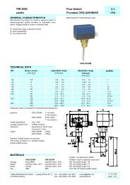
Description of the measuring principle1 Description of the measuring principleMeasuring principle<strong>VEGABAR</strong> <strong>14</strong>The sensor element of <strong>VEGABAR</strong> <strong>14</strong> is the dry ceramic-capacitiveCERTEC ® measuring cell. Base element and diaphragmconsist of high purity sapphire-ceramic ® .The process pressure causes via the diaphragm a change in anelec. parameter of the measuring cell. This change is convertedinto an appropriate output signal.Wi<strong>de</strong> application range16 µmFig. 1: Configuration of the CERTEC ® measuring cell in <strong>VEGABAR</strong> <strong>14</strong>1 Diaphragm2 Sol<strong>de</strong>red glass bond3 Base elementThe advantages of the CERTEC ® measuring cell are:l Very high overload resistancel No hysteresisl Excellent long-term stabilityl Completely front flush installationl Good corrosion resistancel Very high abrasion resistance123<strong>VEGABAR</strong> <strong>14</strong> and <strong>17</strong> pressure transmitters are suitable for processpressure measurement of gases, vapours and liquids. Suitableversions are also available for viscous liquids and corrosiveor aggressive products. The main area of application is mechanicalengineering and plant construction.<strong>VEGABAR</strong> <strong>14</strong> and <strong>17</strong> pressure transmitters are cost-effectiveinstruments with small dimensions for standard applications with4 … 20 mA signal output. They offer sufficient accuracy as well asflush process fittings, but have limited adjustment options.<strong>VEGABAR</strong> <strong>17</strong>In <strong>VEGABAR</strong> <strong>17</strong>, a measuring cell with piezoresistive sensorelement containing an internal transmission liquid is used formeasuring ranges up to 16 bar. The process diaphragm is ma<strong>de</strong>of stainless steel.For measuring ranges from 25 bar, there is a dry strain gauge(DMS) mounted on the back si<strong>de</strong> of the stainless steel processdiaphragm.The process pressure causes via the diaphragm a change in anelec. parameter of the measuring cell. This change is convertedinto an appropriate output signal.124 3Fig. 2: Configuration of a piezoresistive measuring cell with <strong>VEGABAR</strong> <strong>17</strong>1 Sensor element2 Base element3 Diaphragm4 Silicone oil29730-EN-060411The advantages of the piezoresistive measuring cell are:l Elastomere-freel Wetted parts of stainless steell small diameter, therefore small process fittings possiblel small hysteresisProcess pressure – Pressure measurement 3
Type overview2 Type overview<strong>VEGABAR</strong> <strong>14</strong> <strong>VEGABAR</strong> <strong>17</strong>Measuring cell: CERTEC ® Piezoresistive/DMSDiaphragm: Ceramic Metal<strong>Product</strong>s: Gases, vapours and liquids gases, vapours and liquids, also viscous products andfoodstuffsProcess fitting:G½ A or M20x1.5 acc. to EN 837, G½ A inner G¼ A, ½ NPTinner ¼ NPTMaterial: 316L 316TiOil and grease-free/foroxygen applicationsMeasuring range:Process temperature: -40 … +100 °C(-40 … +212 °F)--/-- yes/yes-1 … 0.6 bar up to 0 … 60 bar (-<strong>14</strong>.5 … 8.7 psi up to0 … 870 psi)Deviation in characteristics:
Mounting information3 Mounting informationInstallation position<strong>VEGABAR</strong> functions in any installation position. Depending onthe measuring system, the installation position can influence themeasurement. This can be compensated by a position correction.The instruments with manometer connection acc. to EN 837 aremounted acc. to the directives for manometers (DIN EN 839-2).<strong>Information</strong>:We recommend using lock fittings, measuring instrumenthol<strong>de</strong>rs and siphons from the line of VEGA accessories.29730-EN-060411Process pressure – Pressure measurement 5
Electrical connection4 Electrical connection4.1 General requirementsThe supply voltage range can differ <strong>de</strong>pending on the instrumentversion. The exact range is stated in the "Technical data".Take note of country-specific installation standards (e.g. the VDEregulations in Germany) as well as prevailing safety regulationsand acci<strong>de</strong>nt prevention rules.In hazardous areas you should take note of the appropriateregulations, conformity and type approval certificatesof the sensors and power supply units.4.5 Wiring plans - <strong>VEGABAR</strong> <strong>14</strong>Angle plug connector acc. to DIN 43650A+132-<strong>14</strong>.2 Voltage supplyPower supply and current signal are carried over the same twowireconnection cable. The requirements on the power supply arestated in the Technical Data of this <strong>Product</strong> <strong>Information</strong> manual.The VEGA power supply units VEGATRENN <strong>14</strong>9AEx, VEGAS-TAB 690, VEGADIS 371 as well as the VEGAMET signal conditioninginstruments are suitable for power supply. When one ofthese instruments is used, a reliable separation of the supplycircuit from the mains circuits acc. to DIN VDE 0106 part 101and the protection class is ensured.4.3 Connection cableGeneralThe sensors are connected with standard two-wire cable withoutscreen. An outer cable diameter of 5 … 9 mm ensures the sealeffect of the cable entry.If electromagnetic interference is expected, screened cableshould be used for the signal lines.Ex applicationsIn Ex applications, the corresponding installation regulationsmust be noted for the connection cable.4.4 Cable screening and groundingThe cable screen must be connected on both ends to groundpotential.If potential equalisation currents are expected, the connection onthe evaluation si<strong>de</strong> must be provi<strong>de</strong>d via a ceramic capacitor (e.g.1 nF, 1500 V).Fig. 3: Wiring plan, angle plug connector acc. to DIN 43650A, bottom view of theplug1 Power supply and signal outputRound plug connector M12x1Fig. 4: Wiring plan circular plug connector M12x11 Power supply and signal outputCable outletFig. 5: Wiring plan cable outlet 1)1 br (+) power supply and signal output2 bl (-) power supply and signal output3 Cable screen4 Breather capillaries34341212+-11)The cables bl, ge, sw, ws are not connected.29730-EN-0604116 Process pressure – Pressure measurement
Electrical connection4.6 Wiring plans - <strong>VEGABAR</strong> <strong>17</strong>Angle plug connector acc. to DIN 43650ATerminal housing+12Fig. 6: Wiring plan, angle plug connector acc. to DIN 43650A, bottom view of theplug1 Power supply and signal outputRound plug connector M12x13-11234 5Fig. 9: Wiring plan, terminal housing1 To power supply or processing system2 Control instrument (4 … 20 mA measurement)+––+12+43121-Fig. 7: Wiring plan circular plug connector M12x11 Power supply and signal outputCable outlet3412Fig. 8: Wiring plan cable outlet 2)1 br (+) power supply and signal output2 gn (-) power supply and signal output3 Cable screen4 Breather capillaries29730-EN-0604112)The cables bl, ge, sw, ws are not connected.Process pressure – Pressure measurement 7
Adjustment5 Adjustment5.1 Zero point correction on <strong>VEGABAR</strong> <strong>14</strong><strong>VEGABAR</strong> <strong>14</strong> with angled plug connector enables a zero pointadjustment ±1 mA via an integrated potentiometer.Terminal housingFig. 12: Adjustment zero and spanZSzerospanFig. 10: Adjustment of the zero point5.2 Zero/span adjustment with <strong>VEGABAR</strong> <strong>17</strong><strong>VEGABAR</strong> <strong>17</strong> offers a zero/span adjustment ±10 % via two integratedpotentiometers.Angle and circular plug connector, cable outletFig. 11: Adjustment zero and spanSZspanzero29730-EN-0604118 Process pressure – Pressure measurement
Technical data6 Technical dataGeneral data<strong>VEGABAR</strong> <strong>14</strong>Materials, wetted parts- Process fitting 316L- Diaphragm sapphire ceramic ® (99.9 % oxi<strong>de</strong> ceramic)- Process seal Viton, EPDMMaterials, non-wetted parts- Housing brass nickel-platedMaterials, non-wetted parts, plug connector DIN 43650A- Contact, housing plug PA- Contact surface Sn- Plug seal NBRMaterials, non-wetted parts, plug connector M12x1- Carrier material for contacts PA- Contact CuZn, nickel layer and 0.8 µm gold-plated- Plug seal FKMMaterials, non-wetted parts, cable outlet- Cable gland PA- Cable PURWeightapprox. 0.5 kg (1.1 lbs)<strong>VEGABAR</strong> <strong>17</strong>Materials, wetted parts- Process fitting 316Ti- Diaphragm 316Ti- Diaphragm with front flush version 316Ti, Hastelloy C4- Seal ring, O-ring Viton, EPDM, NBRMaterials, non-wetted parts- Internal transmission liquid Synthetic oil, Halocarbon oil 3)4)- Housing 316Ti- Terminal housing 316Ti- Ground terminal 316Ti- Plug PA- Cable gland PA, 316Ti- Plug seal silicone- Connection cable PURWeight- Version with plug connector, cable outlet approx. 0.2 kg (approx. 0.44 lbs)- Version with terminal housing approx. 0.35 kg (approx. 0.77 lbs)Output variable29730-EN-0604113)4)5)<strong>VEGABAR</strong> <strong>14</strong>Output signalZero point adjustable 5)RangeCurrent limitationRise time (0 … 63 %)<strong>VEGABAR</strong> <strong>17</strong>Output signal4 … 20 mA4 mA, ±1 mA3 … 23 mA23 mA5 ms4 … 20 mAZero and span adjustable via potentiometer ±10 %Adjustment time- Standard
Technical dataPermissible load- with 11 V 0 Ohm- with 30 V 950 OhmInput variableParameterMeasuring rangesPressuresee product co<strong>de</strong>Reference conditions and influencing variables (similar to DIN EN 60770-1)Reference conditions acc. to DIN EN 61298-1- Temperature +18 … +30 °C (+64 … +86 °F)- Relative humidity 45 … 75 %- Atmospheric pressure 860 … 1060 mbar/86 … 106 kPa (12.5 … 15.4 psi)Determination of characteristics limit point adjustment acc. to DIN 16086CharacteristicsLinearCalibration positionupright, diaphragm points downwardInfluence of the installation position<strong>de</strong>pending on the isolating diaphragm versionDeviation in characteristics<strong>VEGABAR</strong> <strong>14</strong>Deviation in characteristics 6)
Technical data<strong>VEGABAR</strong> <strong>17</strong>Ambient temperature- Standard -20 … +80 °C (-4 … +<strong>17</strong>6 °F)Storage and transport temperature-40 … +100 °C (-40 … +212 °F)Process conditions<strong>VEGABAR</strong> <strong>14</strong><strong>Product</strong> temperature with measuring cell seal- Viton -20 … +100 °C (-40 … +212 °F)- EPDM -40 … +100 °C (-40 … +212 °F)Vibration resistance mechanical vibrations with 4 g and 5 … 100 Hz 12)<strong>VEGABAR</strong> <strong>17</strong><strong>Product</strong> temperature- Standard -30 … +100 °C (-22 … +212 °F)- exten<strong>de</strong>d -40 … +125 °C (-40 … +257 °F)- with cooling element -20 … +150 °C (-4 … +302 °F)- EEx ia version -20 … +80 °C (-4 … +<strong>17</strong>6 °F)- Version for oxygen applications -30 … +60 °C (-22 … +<strong>14</strong>0 °F)Calibration positionupright, diaphragm points downwardShock resistance600 g acc. to IEC 60068-2-27 (mechanical shock)Vibration resistance10 g acc. to IEC 60068-2-6 (vibration at resonance)Electromechanical dataAngled plug connector4-pole acc. to DIN 43560ACable glandPG 9 (cable-ø 4.5 … 7 mm)Circular plug connector4-pole M12x1Cable outlet (<strong>VEGABAR</strong> <strong>14</strong> only 5 m)1.5 m; 3 m; 5 m; 10 m; cable with inner ventilationSpring-loa<strong>de</strong>d terminals (<strong>VEGABAR</strong> <strong>17</strong>) for wire cross-sections up to 2.5 mm 2Cable gland, terminal housing (<strong>VEGABAR</strong> <strong>17</strong>)M20x1.5 (cable-ø 5 … 9 mm)Voltage supply<strong>VEGABAR</strong> <strong>14</strong>Supply voltage12 … 30 VDC- Permissible residual ripple U ss
Technical dataApprovals 13)<strong>14</strong>)<strong>VEGABAR</strong> <strong>14</strong>PTB Ex-Zone 2<strong>VEGABAR</strong> <strong>17</strong>ATEXShip approvalATEX II 1/2G EExiaIIC T6; ATEX II 2G EExiaIIC T6; ATEX II 1/2G 2GEExiaIIC T6; ATEX II 1/2G 2GEExiaIIC T6 + ATEX II 1/2DIP6XT+ M1GLCE conformity<strong>VEGABAR</strong> <strong>14</strong>EMC (89/336/EWG) Emission EN 500081-1: 1992, Susceptibility EN 580082-2: 1995LVD (73/23/EWG) EN 61010-1: 1993<strong>VEGABAR</strong> <strong>17</strong>EMC (89/336/EWG) EN 61326: 2002DGRL (97/23/EG)Module HEnvironmental instructionsVEGA environment management system 15) certified acc. to DIN EN ISO <strong>14</strong>00113)<strong>14</strong>)15)Deviating data in Ex applications: see separate safety instructions.You can find <strong>de</strong>tailed information un<strong>de</strong>r www.vega.com.You can find <strong>de</strong>tailed information un<strong>de</strong>r www.vega.com.29730-EN-06041112 Process pressure – Pressure measurement
Dimensions7 Dimensions<strong>VEGABAR</strong> <strong>14</strong><strong>VEGABAR</strong> <strong>17</strong>, terminal housing49,5mm(1 61/64")36mm(1 27/64")25mm (63/64")45mm (1 3/4")max. 90mm (3 35/64")ø 61mm (2 13/32")151mm (5 15/16")34mm(1 11/32")SW27ø 38mm(1 1/2")G½A124mm (4 7/8")31mm(1 7/32")G½A<strong>14</strong>2mm (5 19/32")28mm(1 7/64")ø 27mm(1 1/16")SW41G1B138mm (5 7/16")20,5mm(13/16")138mm (5 7/16")20,5mm(13/16")G1BSW27G1/2B23mm (29/32")3mm (1/8")ø 3mm (1/8")ø 6mm (1/4")20mm (25/32")3mm (1/8")G1/4ø <strong>17</strong>,5mm(11/16")ø 30mm(1 3/16")841/84L/84B10mm(25/64")ø 30mm(1 3/16")851/85L/85B10mm(25/64")ø 18mm(45/64")861/86L/86BGVGP132mm (5 13/64")36mm (1 27/64")10mm (25/64")½"NPT25mm (63/64")M12x11/4"NPT15mm (19/32")20mm (25/32")36mm(1 27/64")25mm (63/64")5mm (13/64")M20x1,5ø 3mm (1/8")ø 6mm (1/4")~128mm (5 3/64")13mm(33/64")2mm~135mm (5 5/16")20mm(25/32")~ <strong>17</strong>,52mm(5/64")G1/4Bø 5mm(13/64")ø 9,5mm(3/8")GBX1 2~ <strong>17</strong>,53mm(1/8") 3mm~128mm (5 3/64")G1/2Bø 6mm(15/64")ø <strong>17</strong>,5mm(11/16")GDX13mm(33/64")NBX1/4NPT~134mm (5 9/32")19mm(3/4")NDX1/2NPTGNGBG1/2BG1BFig. 13: <strong>VEGABAR</strong> <strong>14</strong><strong>VEGABAR</strong> <strong>17</strong>, standard housingFig. 15: <strong>VEGABAR</strong>, terminal housing1 Cooling element G½ B2 Cooling element G1 B~116mm (4 9/16")13mm~135mm (5 5/16")(33/64")28mm(1 7/64")2mm~ <strong>17</strong>,52mm(5/64")ø 27mm(1 1/16")SW41G1Bø 30mm(1 3/16")841/84L/84BG1/4Bø 5mm(13/64")ø 9,5mm(3/8")GBX~ <strong>17</strong>,5~123mm (4 27/32") ~126mm (4 61/64")20,5mm10mm (13/16")(25/64")G1/2BG1BG1Bø 30mm(1 3/16")851/85L/85B~126mm (4 61/64")20,5mm10mm (13/16")(25/64")SW27G1/2Bø 18mm(45/64")20mm(25/32")~116mm (4 9/16")~123mm (4 27/32")3mm(1/8") 3mmø 6mm(15/64")ø <strong>17</strong>,5mm(11/16")GDXG1/2B1/4NPT~48mm(1 57/64")13mm(33/64")861/86L/86B27,5mm(1 5/64")13,5mm(<strong>17</strong>/32")19mm(3/4")NBXNDX1 2 3 4 512mm1/2NPT(15/32")29730-EN-060411Fig. <strong>14</strong>: <strong>VEGABAR</strong>, dimensions with * in brackets are valid for Ex versions1 Cooling element G½ B2 Cooling element G1 B3 Plug acc. to DIN 43650A4 Cable outlet5 M12x1 plug connectionProcess pressure – Pressure measurement 13
<strong>Product</strong> co<strong>de</strong>8 <strong>Product</strong> co<strong>de</strong><strong>VEGABAR</strong> <strong>14</strong>BAR<strong>14</strong>Approval.X withoutPressure / Measuring range1S rel. / 0...0.1 bar (0...10 kPa)1T rel. / 0...0.25 bar (0...25 kPa)1U rel. / 0...0.4 bar (0...40 kPa)1V rel. / 0...0.6 bar (0...60 kPa)1A rel. / 0...1 bar (0...100 kPa)1B rel. / 0...1.6 bar (0...160 kPa)1C rel. / 0...2.5 bar (0...250 kPa)1D rel. / 0...4 bar (0...400 kPa)1E rel. / 0...6 bar (0...600 kPa)1F rel. / 0...10 bar (0...1000 kPa)1G rel. / 0...16 bar (0...1600 kPa)1H rel. / 0...25 bar (0...2500 kPa)1I rel. / 0...40 bar (0...4000 kPa)1J rel. / 0...60 bar (0...6000 kPa)3T rel. / -0.1...+0.1 bar (-10...+10 kPa)3U rel. / -0.2...+0.2 bar (-20...+20 kPa)3A rel. / -0.5...+0.5 bar (-50...+50 kPa)3B rel. / -1...+0.6 bar (-100...+60 kPa)3W rel. / -1...+1 bar (-100...+100 kPa)3C rel. / -1...+1.5 bar (-100...+150 kPa)3D rel. / -1...+3 bar (-100...+300 kPa)3E rel. / -1...+5 bar (-100...+500 kPa)3F rel. / -1...+9 bar (-100...+900 kPa)3G rel. / -1...+15 bar (-100...+1500 kPa)2A abs. / 0...1 bar (0..100kPa)2B abs. / 0...1.6 bar (0...160kPa)2C abs. / 0...2.5 bar (0...250kPa)2D abs. / 0...4 bar (0...400kPa)2E abs. / 0...6 bar (0...600kPa)2F abs. / 0...10 bar (0...1000kPa)2G abs. / 0...16 bar (0...1600kPa)Electrical connection / ProtectionA1 4-pole plug connection DIN43650-A PG9 / IP65C1 Direct cable outlet with 5 m cable / IP67M1 Circular plug conn.,4-pole w.screwed plug M12x1 / IP65Process connection / MaterialGV G½A, manometer connec. EN837 PN60 / 316TiGP G½A, inner G¼A PN60 / 316TiGN ½NPT inner ¼NPT PN60 / 316TiGB M20x1,5 manometer connection EN837 PN60 / 316TiGG Thread G1½A PN60 / 316LSeal measuring cell1 FKM (Viton)3 EPDM<strong>VEGABAR</strong> <strong>17</strong>ApprovalZ withoutA ATEX II 1/2G, 2G EEx ia IIC T6D ATEX II 1/2G, 2G EEx ia IIC T6+ATEX II 1/2D IP6X T+M1 1)S ATEX II 1/2G, EEx ia IIC T6 + Ship approvalProcess connection / MaterialGDX G½B, manometer connection / 316TiTBX G½A inner G¼A / 1.4571(316Ti)861 Thread G½B, flush / 316Ti w. o-ring, >1,6 bar / NBR86L Thread G½B, flush / 316Ti w. o-ring, >1.6bar / Viton86B Thread G½B, flush / 316Ti w.o-ring, >1.6 bar / EPDM851 Thread G1B, flush / 316Ti w.o-ring, up to 1.6bar / NBR85L Thread G1B,flush/316Ti w.o-ring, up to 1.6bar / Viton85B Thread G1B, flush / 316Ti w.o-ring,up to 1.6bar / EPDM84L Thread G1B, hygienic / 316Ti, max.25 bar / Viton 2)84B Thread G1B, hygienic / 316Ti, max.25 bar / EPDM 2)GBX G¼B manometer connection / 316TiNBX Thread ¼NPT / 316TiNDX Thread ½NPT / 316TiPressureB Gauge pressureS Absolute pressure 3)Measuring rangeLA -0.1...0 bar (-10...0 kPa)KA -0.16...0 bar (-16...0 kPa)GA -0.25...0 bar (-25...0 kPa)FA -0.4...0 bar (-40...0 kPa)DA -0.6...0 bar (-60...0 kPa)CA -1...0 bar (-100...0 kPa)AL 0...0.1 bar (0...10 kPa)AM 0...0.16 bar (0...16 kPa)AN 0...0.25 bar (0...25 kPa)BB 0...0.4 bar (0...40 kPa)BC 0...0.6 bar (0...60 kPa)BD 0...1 bar (0...100 kPa)BE 0...1.6 bar (0...160 kPa)BF 0...2.5 bar (0...250 kPa)BG 0...4 bar (0...400 kPa)BH 0...6 bar (0...600 kPa)BI 0...10 bar (0...1000 kPa)BK 0...16 bar (0...1600 kPa)BL 0...25 bar (0...2500 kPa)BM 0...40 bar (0...4000 kPa)BN 0...60 bar (0...6000 kPa)BO 0...100 bar (0...10000 kPa)BP 0...160 bar (0...16000 kPa)BQ 0...250 bar (0...25000 kPa)BS 0...400 bar (0...40000 kPa)BT 0...600 bar (0...60000 kPa)Electrical connection / ProtectionA4 Angle plug connector DIN43650 / IP65M4 Circular plug connector, 4-pole w. screwed plug M12x1DL Cable outlet / IP67DM Cable outlet / IP68FW Terminal housing 316L, plastic cable gland / IP67FV Terminal housing 316L, stainless steel cable gland/IP67Cable lengthZ withoutC 1.5 mE 3 mG 5 mI 10 mFeatures / Cleaning procedureZ withoutE oil and grease-freeA oil and grease free for oxygen applications 4)G Fill fluid and materials suitable for foodstuffsTemperature rangeA -30...100°C (standard product temperature)B -40...125°C (product temperature)C -20...150°C (product temperature, with cooling element)U -20...80°C (ambient temperature with EEx ia) 5)Test certificateZ no1 yes 6)BR<strong>17</strong>.1) Only with Electrical connection/Protection "DM"2) Only with Temperature range " C "3) Only for Measuring ranges 0...0.25 bar up to 0...16 bar4) Medium temperature max. 60°C5) See EC type approval certificate6) Price and <strong>de</strong>livery time on request29730-EN-060411<strong>14</strong> Process pressure – Pressure measurement
29730-EN-060411Process pressure – Pressure measurement 15
29730-EN-060411