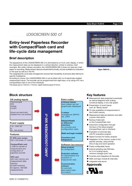
Entry-level Paperless Recorder with CompactFlash card and life ...
Entry-level Paperless Recorder with CompactFlash card and life ...
Entry-level Paperless Recorder with CompactFlash card and life ...

You also want an ePaper? Increase the reach of your titles
YUMPU automatically turns print PDFs into web optimized ePapers that Google loves.
JUMO GmbH & Co. KG • 36035 Fulda, Germany Data Sheet 70.6510 Page 2/10Technical dataAnalog inputsInput for DC voltage, DC currentBasic range Accuracy Input resistance-20 to +70mV-3 to +105mV-10 to +210mV-0.5 to +12V-0.05 to +1.2V-1.2 to +1.2V-10 to +12VShortest spanRange start/end-2 to +22mA-22 to +22mAShortest spanRange start/endThermocouple±80μV±100μV±240μV±6mV±1mV±2mV±12mV±20μA±44μA5mVR IN ≥ 1 MΩR IN ≥ 1 MΩR IN ≥ 1 MΩR IN ≥ 470 kΩR IN ≥ 470 kΩR IN ≥ 470 kΩR IN ≥ 470 kΩfreely programmable <strong>with</strong>in the limits in 0.01 mV steps0.5mAburden voltage ≤ 1Vburden voltage ≤ 1Vfreely programmable <strong>with</strong>in the limits in 0.01 mA stepsOverrange / underrange according to NAMUR NE 43Sampling cycleInput filterTest voltage for electrical isolationResolution3 or 6 channels 250msec2nd order digital filter; filter constant adjustable from 0 to 10.0sec350V (via optocoupler)>14 bitDesignation Type St<strong>and</strong>ard Meas. range Accuracy 1Fe-Con L DIN 43 710Fe-Con J EN 60 584Cu-Con U DIN 43 710Cu-Con T EN 60 584NiCr-Ni K EN 60 584NiCr-Con E EN 60 584NiCrSi-NiSi N EN 60 584Pt10Rh-Pt S EN 60 584Pt13Rh-Pt R EN 60 584Pt30Rh-Pt6Rh B EN 60 584W3Re/W25Re DW5Re/W26Re CChromel-Copel GOST R 8.585-2001Shortest spanRange start/endCold junction-200 to +900°C-210 to +1200°C-200 to +600°C-270 to +400°C-270 to +1372°C-270 to +1000°C-270 to +1300°C-50 to +1768°C-50 to +1768°C0 to 1820°C0 to 2400°C0 to 2320°C-200 to +800°CType L, J, U, T, K, E, N, chromel-copel:Type S, R, B, D, C:±0.1%±0.1% from -100°C±0.1% from -150°C±0.15% from -150°C±0.1% from -80°C±0.1% from -80°C±0.1% from -80°C±0.15% from 0°C±0.15% from 0°C±0.15% from 400°C±0.15% from 500°C±0.15% from 500°C±0.1%100°C500°Cfreely programmable <strong>with</strong>in the limits, in 0.1°C stepsPt100 internal or thermostat external constantCold junction accuracy (internal) ± 1°CCold junction temperature (external)Sampling cycleInput filterTest voltage for electrical isolationResolution-50 to +150°C, adjustable3 or 6 channels, 250msec2nd order digital filter; filter constant adjustable from 0 to 10.0sec350V (via optocoupler)>14 bitSpecial features also programmable in °F1 The accuracy refers to the maximum measuring range. The accuracy is reduced <strong>with</strong> short spans.2009-12-15/00467412
JUMO GmbH & Co. KG • 36035 Fulda, Germany Data Sheet 70.6510 Page 3/10RTDDesignation St<strong>and</strong>ard Connection circuit Meas. range Accuracy Measuring currentPt100 EN 60 751(TC = 3.85*10 -3 1/°C)Pt100 JIS 1604(TC = 3.917*10 -3 1/°C)Pt100 GOST 6651-94 A.1(TC = 3.91*10 -3 1/°C)Pt500 EN 60 751(TC = 3.85*10 -3 1/°C)Pt1000 EN 60 751(TC = 3.85*10 -3 1/°C)Ni100 DIN 43 760(TC = 6.18*10 -3 1/°C)Pt50 ST RGW 1057 1985(TC = 3.91*10 -3 1/°C)Cu 50 GOST 6651-94 A.3(TC = 4.28*10 -3 1/°C)Cu100 GOST 6651-94 A.4(TC = 4.26*10 -3 1/°C)Connection circuit2/3-wire2/3-wire4-wire4-wire2/3-wire2/3-wire4-wire4-wire2/3-wire2/3-wire4-wire4-wire2/3-wire2/3-wire4-wire4-wire2/3-wire2/3-wire4-wire4-wire2/3-wire4-wire2/3-wire2/3-wire4-wire4-wire2/3-wire2/3-wire4-wire4-wire2/3-wire4-wire-200 to +100°C-200 to +850°C-200 to +100°C-200 to +850°C-200 to +100°C-200 to +650°C-200 to +100°C-200 to +650°C-200 to +100°C-200 to +850°C-200 to +100°C-200 to +850°C-200 to +100°C-200 to +850°C-200 to +100°C-200 to +850°C-200 to +100°C-200 to +850°C-200 to +100°C-200 to +850°C-60 to +180°C-60 to +180°C-200 to +100°C-200 to +1100°C-200 to +100°C-200 to +1100°C-50 to +100°C-50 to +200°C-50 to +100°C-50 to +200°C-50 to +200°C-50 to +200°C±0.5°C±0.8°C±0.5°C±0.5°C±0,5°C±0.8°C±0.5°C±0.5°C±0.5°C±0.8°C±0.5°C±0.5°C±0.5°C±0.8°C±0.5°C±0.5°C±0.5°C±0.8°C±0.5°C±0.5°C±0.4°C±0.4°C±0.5°C±0.9°C±0.5°C±0.6°C±0.5°C±0.9°C±0.5°C±0.6°C±0.5°C±0.5°C2-, 3-, or 4-wire circuit500μA250μA500μA250μA500μA250μA500μA250μA500μA250μA500μA250μA250μA250μA250μA250μA500μA250μA500μA250μA500μA500μA500μA250μA500μA250μA500μA250μA500μA250μA500μA500μAShortest span 15°CSensor lead resistancemax. 30 Ω per conductor for 3-wire/4-wire circuitmax. 10Ω per conductor for 2-wire circuitRange start/endfreely programmable <strong>with</strong>in the limits in 0.1°C stepsSampling cycle3 or 6 channels, 250msecInput filter2nd order digital filter; filter constant adjustable from 0 to 10secTest voltage for electrical isolationResolution350V (via optocoupler)> 14bitTransducer short circuit/breakShort circuit 1 Break 1Thermocouple not detected detectedRTD detected detectedVoltage ≤ 210mV not detected detectedVoltage > 210mV not detected not detectedCurrent not detected not detected1 Programmable reaction of device, e.g. trigger an alarmBinary inputs (extra code)QuantityLevelSampling cycle(binary inputs, <strong>with</strong>out counter function)Count frequency(binary inputs, <strong>with</strong> counter function)Auxiliary voltage (output)4, to DIN 19 240; 1Hz max., 32V max.logic “0”: -3 to +5V, logic “1”: 12 — 30V1sec30Hz max.24V ±10%, 50mA (short-circuit proof)2009-12-15/00467412
JUMO GmbH & Co. KG • 36035 Fulda, Germany Data Sheet 70.6510 Page 4/10Outputs (extra code)3 relays changeover (SPDT) (3A, 230V)InterfacesSetup interface (st<strong>and</strong>ard)RS232 / RS485 (extra code)Ethernet (extra code)to read <strong>and</strong> write measurement, instrument, <strong>and</strong> configuration data (Modbus protocol)to read <strong>and</strong> write measurement, instrument, <strong>and</strong> configuration data (Modbus protocol)to read <strong>and</strong> write measurement, instrument <strong>and</strong> configuration data (Modbus-TCP protocol)ScreenResolutionElectrical dataHousing320 x 240 pixelsSize 5“Number of colorsScreen refresh rateContrast settingScreen saver (switch-off)Supply(switch-mode PSU)Test voltages (type test)- electrical supply to measuring circuit- electrical supply to housing(protective earth)- measuring circuits to othermeasuring circuits <strong>and</strong> housing- electrical isolation betweenthe analog inputsSupply voltage errorPower consumption27 colors≥150Hzadjustable on instrumentthrough waiting time or control signal110 — 240 V AC +10/-15%, 48 — 63Hz or20 — 53V AC/DC, 48 — 63Hzto EN 61 010, Part 1, March 1994overvoltage category II, pollution degree 2for supply voltage: AC 2.3kV/50Hz, 1min,for supply voltage: AC/DC 510V/50Hz, 1minfor supply voltage: AC 2.3kV/50Hz, 1min,for supply voltage: AC/DC 510V/50Hz, 1min350V/50Hz, 1minup to 30V AC <strong>and</strong> 50V DC< 0.1% of range spanapprox. 25VAData backup see page 6Electrical connectionElectromagnetic compatibility (EMC)- interference emission- interference immunityAt the back, via pluggable screw terminals,conductor cross-section ≤ 2.5mm 2 or 2 x 1.5mm 2 <strong>with</strong> core end ferrules.EN 61 326-1Class A - only for industrial use -to industrial requirementsSafety regulations to EN 61 010Enclosure protectionto EN 60 529 category 2, front IP54, back IP20Ambient temperature rangeAmbient temperature errorStorage temperature rangeHousing type- housing doorBezel sizeDepth behind panelPanel cut-outPanel thickness0 to +50°C0.03%/°C-20 to +60°Chousing for flush panel mounting to IEC 61 554, galvanized steel sheetzinc die-casting144mm x 144mm214mm, including connectors138 +1.0 mm x 138 +1.0 mm2 — 40mmHousing mounting in panel to DIN 43 834Climatic conditions≤ 75% relative humidity, no condensationOperating positionunrestricted, but taking into account the viewing angle of the screen,horizontally ±50°, vertically ±30°Enclosure protection to EN 60 529 Category 2,IP54 front (IP65 <strong>with</strong> extra code 266), IP20 backWeightapprox. 3.5kgApprovals/marks of conformityMark ofconformityc UL usTestinglaboratoryUnderwritersLaboratoriesCertificates /certification numbersTest basisE 201387 UL 61010-1CAN/CSA-C22.2 No. 61010-1valid forthe flush-mounted instrument;not in conjunction <strong>with</strong> extracode 3502009-12-15/00467412
JUMO GmbH & Co. KG • 36035 Fulda, Germany Data Sheet 70.6510 Page 7/10Presentation modes on the instrumentMain menuVisualizationVisualizationk Branching into the menus (<strong>level</strong>s)- visualization- parameterization- configuration- event list- CF <strong>card</strong> manager- device infoVisualizationk Analog channels <strong>and</strong> event tracesk In addition to the curves, measurementscan be made visible in numerical form,<strong>with</strong> scaling or as a bar graphs.k Softkeys can be made visible or hidden.Visualizationk Graphical presentation of the analogchannels (<strong>with</strong>out event traces)k Display of scaling <strong>and</strong>limit markers for the channelsHistory presentationk Display mode “Measurements”(numerical display)k Display mode “Scaling”including limit markersk Display mode “Bar graph”including limit markersConfigurationk The graphical presentation can beswitched off in favor of a larger numericaldisplay.Parameterizationk All measurement data stored in the mainmemory are shown as curves at differentzoom <strong>level</strong>s.k Numerical display of the measurementsfor the analog channels at the cursorposition.k Shifting of the visible section <strong>with</strong>in thestored measurement data.k When recorded as an envelope:the maximum or minimum value displaycan be changed <strong>with</strong>in the channel line.Event listk Configuration from instrument keysk Password-protectedk Configuration can be transferred to CF<strong>card</strong>k Configuration data can be read/alteredthrough the setup programk General settings <strong>with</strong>out passwordk Selection of the presentation mode,such as: analog data <strong>and</strong>/or event traces<strong>with</strong>/<strong>with</strong>out channel linek Important events in plain text(alarm messages, external textsor system messages)2009-12-15/00467412
JUMO GmbH & Co. KG • 36035 Fulda, Germany Data Sheet 70.6510 Page 8/10Connection diagramRear view of a 3/6-channel paperless recorder <strong>with</strong> pluggable screw terminals(L-) (L+)PE N L130.31.32.20.33.111121.Cut-outs for cables ties<strong>with</strong> foot for strain relief1 1 14. 5.6.1 1 11. 2.3.Terminal assignments for 3/6-channel paperless recorderDiagramAnalog inputsConnectorThermocouple 1 to 6RTD in 2-wire circuit 1 to 6RTD in 3-wire circuit 1 to 6RTD in 4-wire circuit 1 to 6Voltage input ≤ 210mV 1 to 6Voltage input > 210mV 1 to 6Current input 1 to 62009-12-15/00467412
JUMO GmbH & Co. KG • 36035 Fulda, Germany Data Sheet 70.6510 Page 9/10SupplySupplyPEN (L-)L1 (L+)Relay outputs (extra code)Relays K1, K2, K3changeover (SPDT)30, 31, 322 31Setup interface (included in delivery)The setup interface can be found behind a protective flapon the front of the instrument.Setup interfaceInterfaces (extra code)RS2329-pole SUB-D socket(switchable to RS485)RS4859-pole SUB-D socket(switchable to RS232)EthernetRJ45 socket20 2 RxD Received Data3 TxD Transmitted Data5 GND Ground20 3 TxD+/RxD+ Transmitted/Received Data +5 GND Ground8 TxD-/RxD- Transmitted/Received Data -21 1 TX+ Transmitted Data +2 TX- Transmitted Data -3 RX+ Received Data +6 RX- Received Data -Binary inputs (extra code)Supply voltage 24V/50mABinary inputsvoltage-controlledLOW = -3 to +5V DCHIGH = 12 to 30V DCDimensions336 +24V auxiliary supply5 GND4 binary input 13 binary input 22 binary input 31 binary input 46 5 4 3 2 1+ –Example: binary input 4, operated from theinternal supply voltageSize 26 increases to 27 if the IP65 seal is used.2009-12-15/00467412
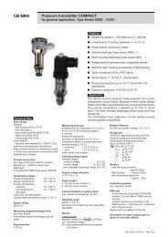
JUMO GmbH & Co. KG • 36035 Fulda, Germany Data Sheet 70.6510 Page 10/10Order details<strong>Entry</strong>-<strong>level</strong> <strong>Paperless</strong> <strong>Recorder</strong> <strong>with</strong> <strong>CompactFlash</strong> <strong>card</strong> as storage medium<strong>and</strong> <strong>life</strong>-cycle data management(1) Basic version706510/14 <strong>Paperless</strong> recorder <strong>with</strong> 3 analog inputs706510/24 <strong>Paperless</strong> recorder <strong>with</strong> 3 analog inputsincl. setup <strong>and</strong> PC evaluation program (PCA3000)706510/15 <strong>Paperless</strong> recorder <strong>with</strong> 6 analog inputs706510/25 <strong>Paperless</strong> recorder <strong>with</strong> 6 analog inputsincl. setup <strong>and</strong> PC evaluation program (PCA3000)(2) Supply voltagex x x x 22 20 — 53V AC/DC, 48 — 63Hzx x x x 23 110 — 240V AC +10/-15%, 48 — 63Hz(3) Extra codesx x x x 008 Ethernet interfacex x x x 020 Lithium battery for memory buffering (ex-factory)x x x x 021 Storage capacitor (instead of extra code 020)x x x x 260 Integrators <strong>and</strong> counters, as well as math <strong>and</strong>logic module (the math <strong>and</strong> logic module can onlybe configured through the setup program).x x x x 261 4 binary inputs, 3 relay outputs,serial interface RS232/RS485 (Modbus, Jbus)x x x x 265 Door <strong>with</strong> lock (IP54)x x x x 266 IP65 seal, wide mounting bracketsx x x x 350 Universal carrying case TG-35 1(1) (2) (3)Order code - / , ... 2Order example 706510/14 - 23 / 0201 This extra code is available in combination <strong>with</strong> supply voltage 110—240V AC, not <strong>with</strong> lowsupply voltage. UL approval is not available. The protection type in the carrying casecorresponds to IP20, outside IP20D.2 List extra codes in sequence, separated by commas.St<strong>and</strong>ard accessoriesUniversalcarrying case TG-35226373326366314- for the installation of a paperless recorder<strong>with</strong> bezel size 144mm x 144mm- 326mm x 226mm x 366mm (W x H x D)Cut-out: 138mm x 138mm- The paperless recorder is accessiblefrom the back- 1 Operating Manual B 70.6510.0- 2 mounting brackets- Cable tie <strong>with</strong> foot (can be released), for strain reliefof the connecting cables to the sensorsAccessories (Data Sheet 70.9700)Sales No.- Setup program, multilingual 70/00467262- PC evaluation software (PCA3000), multilingual 70/00431882- PCA communications software (PCC), multilingual 70/00431879- PC interface <strong>with</strong> TTL/RS232 converter <strong>and</strong> adapter (socket) 70/00350260- PC interface <strong>with</strong> USB/TTL converter, adapter (socket) <strong>and</strong>adapter (pins) 70/00456352- Enabling extra code 260(configuration of the math <strong>and</strong> logic moduleonly through the setup program)70/00393217- 256 MB <strong>CompactFlash</strong> memory <strong>card</strong>The CF <strong>card</strong>s specified by JUMO are tested <strong>and</strong> designedfor industrial applications. We do not accept anyresponsibility for other CF <strong>card</strong>s.70/004634622009-12-15/00467412