Young's modulus of elasticity of Schlemm's canal endothelial cells
Young's modulus of elasticity of Schlemm's canal endothelial cells
Young's modulus of elasticity of Schlemm's canal endothelial cells

Create successful ePaper yourself
Turn your PDF publications into a flip-book with our unique Google optimized e-Paper software.
Biomech Model Mechanobiol (2010) 9:19–33DOI 10.1007/s10237-009-0156-3ORIGINAL PAPERYoung’s <strong>modulus</strong> <strong>of</strong> <strong>elasticity</strong> <strong>of</strong> Schlemm’s <strong>canal</strong> <strong>endothelial</strong> <strong>cells</strong>Dehong Zeng · Taras Juzkiw · A. Thomas Read ·Darren W.-H. Chan · Matthew R. Glucksberg ·C. Ross Ethier · Mark JohnsonReceived: 8 July 2008 / Accepted: 2 April 2009 / Published online: 23 April 2009© Springer-Verlag 2009Abstract Schlemm’s <strong>canal</strong> (SC) <strong>endothelial</strong> <strong>cells</strong> are likelyimportant in the physiology and pathophysiology <strong>of</strong> the aqueousdrainage system <strong>of</strong> the eye, particularly in glaucoma.The mechanical stiffness <strong>of</strong> these <strong>cells</strong> determines, in part,the extent to which they can support a pressure gradient andthus can be used to place limits on the flow resistance thatthis layer can generate in the eye. However, little is knownabout the biomechanical properties <strong>of</strong> SC <strong>endothelial</strong> <strong>cells</strong>.Our goal in this study was to estimate the effective Young’s<strong>modulus</strong> <strong>of</strong> <strong>elasticity</strong> <strong>of</strong> normal SC <strong>cells</strong>. To do so, we combinedmagnetic pulling cytometry <strong>of</strong> isolated cultured humanSC <strong>cells</strong> with finite element modeling <strong>of</strong> the mechanicalresponse <strong>of</strong> the cell to traction forces applied by adherentbeads. Preliminary work showed that the immersion angles<strong>of</strong> beads attached to the SC <strong>cells</strong> had a major influence onbead response; therefore, we also measured bead immersionangle by confocal microscopy, using an empirical techniqueto correct for axial distortion <strong>of</strong> the confocal images. Ourresults showed that the upper bound for the effective Young’s<strong>modulus</strong> <strong>of</strong> <strong>elasticity</strong> <strong>of</strong> the cultured SC <strong>cells</strong> examined inthis study, in central, non-nuclear regions, ranged betweenD. Zeng · M. R. Glucksberg · M. Johnson (B)Department <strong>of</strong> Biomedical Engineering,Northwestern University, Evanston, USAe-mail: m-johnson2@northwestern.eduT. Juzkiw · A. T. Read · D. W.-H. Chan · C. R. EthierDepartment <strong>of</strong> Mechanical and Industrial Engineering,University <strong>of</strong> Toronto, Toronto, CanadaC. R. EthierInstitute <strong>of</strong> Biomaterials and Biomedical Engineering,University <strong>of</strong> Toronto, Toronto, CanadaC. R. EthierDepartment <strong>of</strong> Bioengineering, Imperial College London,London, UK1,007 and 3,053 Pa, which is similar to, although somewhatlarger than values that have been measured for other <strong>endothelial</strong>cell types. We compared these values to estimates <strong>of</strong>the <strong>modulus</strong> <strong>of</strong> primate SC <strong>cells</strong> in vivo, based on images<strong>of</strong> these <strong>cells</strong> under pressure loading, and found good agreementat low intraocular pressure (8–15 mm Hg). However,increasing intraocular pressure (22–30 mm Hg) appeared tocause a significant increase in the <strong>modulus</strong> <strong>of</strong> these <strong>cells</strong>.These moduli can be used to estimate the extent to which SC<strong>cells</strong> deform in response to the pressure drop across the innerwall endothelium and thereby estimate the extent to whichthey can generate outflow resistance.Keywords Magnetic bead pulling cytometry · Immersionangle · Cell stiffness · Glaucoma1 IntroductionGlaucoma describes a group <strong>of</strong> potentially blinding oculardisorders. Recent work estimates that worldwide there willbe approximately 60.5 million people with glaucoma in 2010,increasing to 79.6 million by 2020; <strong>of</strong> these, 8.4 million willbe bilaterally blind by 2010, increasing to 11.2 million by2020 (Quigley and Broman 2006). The primary risk factorfor the development <strong>of</strong> vision loss in glaucoma is elevatedpressure within the eye (intraocular pressure, or IOP), andlowering <strong>of</strong> IOP is currently the only therapeutic option withproven efficacy (Kass et al. 2002). IOP is generated as aqueoushumor drains out <strong>of</strong> the eye against the hydrodynamicresistance <strong>of</strong> a series <strong>of</strong> specialized tissues. Most causes <strong>of</strong>elevated IOP leading to glaucoma are due to an increase inflow resistance <strong>of</strong> these tissues, and there is therefore greatinterest in understanding the biomechanics <strong>of</strong> aqueous humordrainage.123
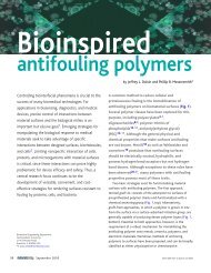
Young’s <strong>modulus</strong> <strong>of</strong> <strong>elasticity</strong> <strong>of</strong> Schlemm’s <strong>canal</strong> <strong>endothelial</strong> <strong>cells</strong> 21Fig. 2 Inverted motorizedmicroscope with bead-pullingsetup including video camera(A), electric micromanipulator(B) and magnetic microneedleassembly; inset shows details <strong>of</strong>(C) with cell culturethrough videomicroscopy (see Fig. 2). Displacements <strong>of</strong> thebeads as a function <strong>of</strong> time were obtained by analyzing thevideomicroscopy images.To estimate an effective Young’s <strong>modulus</strong> <strong>of</strong> <strong>elasticity</strong> <strong>of</strong>the SC <strong>cells</strong> from the results <strong>of</strong> these experiments, we used afinite element model to simulate the displacement <strong>of</strong> a magneticbead attached to a cultured SC cell. We estimated the<strong>modulus</strong> <strong>of</strong> the cell by finding the value that best matched themodel predictions to the experimental data. Bead displacementsin our numerical simulations strongly depended on thedepth to which the magnetic bead embedded in the cell, andthus fluorescence microscopy was used to estimate the depth<strong>of</strong> bead immersion.2.2 Cell cultureHuman SC <strong>cells</strong> were harvested from both eyes <strong>of</strong> a normalhuman donor (76-year-old male) supplied from the NationalDisease Research Interchange (Philadelphia, PA) within 40 hpost-mortem, using a CD31 immunopanning technique asdescribed by Karl et al. (2005). The SC <strong>cells</strong> were plated on60 mm culture dishes (product# 83-1801, Sarstedt, Montreal,Canada) and <strong>cells</strong> in each dish were maintained in 5 ml <strong>of</strong>DMEM with low glucose supplemented with 10% fetal bovineserum (FBS), penicillin (100 unit/ml), streptomycin(100 µg/ml), and L-glutamine (292 µg/ml). The mediumwas changed daily. The <strong>cells</strong> were passaged at confluencewith a 1:12 split ratio (around 4 × 10 4 <strong>cells</strong>/ml).Unlike trabecular meshwork <strong>cells</strong>, SC <strong>cells</strong> express thevon Willebrand factor–receptor complex (vWF) (Stamer et al.1998). Cells were tested for presence <strong>of</strong> vWF using immun<strong>of</strong>luorescenceto confirm that they were SC <strong>cells</strong>. The primaryantibody was rabbit anti-human (1:200 dilution, Sigma)and the secondary antibody was fluorescein isothiocyanateconjugatedgoat anti-rabbit IgG (1:1,000 dilution, Biosource).Cultured <strong>cells</strong> showed positive labeling, confirming that theywere in fact SC <strong>cells</strong>.2.3 Magnetic pulling cytometry2.3.1 Magnetic beadsWe generally followed the methods for magnetic bead pullingcytometry as described by Matthews et al. (2004). We used4.5 µm diameter superparamagnetic, tosyl-activated Dynabeads(product#140.13, Dynal Biotech, Brown Deer, USA).These polystyrene beads have a polyurethane layer embeddedwith p-toluenesulphonyl (tosyl) reactive groups. Thebeads contained iron oxide in the form <strong>of</strong> maghemite(γ -Fe 2 O 3 ) that gave them their superparamagnetic qualities.To promote specific attachment <strong>of</strong> the beads to the <strong>cells</strong>,a synthetic peptide (Peptite-2000, Integra LS, San Diego,USA) that contains the Arg-Gly-Asp (RGD) sequence wasadsorbed hydrophobically onto the bead. 100 µl <strong>of</strong> bead solutionand 10 µl <strong>of</strong> the peptide at a concentration <strong>of</strong> 50 µg/mlwere added to 900 µl <strong>of</strong> 0.1M sodium carbonate buffer (pH9.4). The solution was rotated in an end-over-end rotator for24 h at 4 ◦ C. The coated beads were washed twice in PBSand then stored in PBS at 4 ◦ C at concentration <strong>of</strong> 2 × 10 6beads/100 µl (Wang et al. 1993).2.3.2 Magnetic needle and magnetic force calibrationA magnetic microneedle assembly was the source <strong>of</strong> themagnetic field gradient used to pull the microbeads attachedto the <strong>cells</strong>. The magnetic microneedle assembly consisted<strong>of</strong> a 5-cm long stainless steel sewing needle glued to thetop <strong>of</strong> a permanent neodymium iron boron (NeFeB) disc123
22 D. Zeng et al.Force (pN)50004000300020001000025 50 75 100 125 150 175Distance from Tip (µm)Fig. 3 Horizontal magnetic force on bead as a function <strong>of</strong> distancefrom the tip <strong>of</strong> the microneedle. Solid line is best exponential fitmagnet (26 mm in diameter, 6 mm in height; EdmundIndustrial Optics) that was in turn glued to an aluminum rod(1.25 cm in diameter, 15 cm in length). This assembly wasmounted onto an electric micromanipulator (MP-285, SutterInstruments, California, USA) at an angle <strong>of</strong> 30 ◦ from thehorizontal.The magnitude <strong>of</strong> the horizontal magnetic force appliedto each bead was a function <strong>of</strong> the distance between the needletip and the bead. To calibrate the magnetic force, singlebeads were placed in a 100% glycerol solution (BDH, AnalaR;VWR Scientific) near the needle, and bead motion wastracked by video microscopy. The temperature <strong>of</strong> the glycerolwas measured with a thermocouple, allowing the viscosity <strong>of</strong>the glycerol to be calculated from standard tables (Gilmont2002). The instantaneous horizontal velocity <strong>of</strong> single beadswas obtained through analyzing video microscopic images,and the viscous force on a bead was calculated based onStokes Law (Yih 1988):F = 6πµRU (1)where F was the total viscous force on the bead, µ thedynamic viscosity <strong>of</strong> the glycerol, R the bead radius, andU the bead velocity. Magnetic force decayed as a function <strong>of</strong>distance from the needle tip. The calibration was performedeight times, and the force versus distance data were regressedto an exponential equation (Fig. 3).2.3.3 VideomicroscopyThe motions <strong>of</strong> the beads were imaged using a Zeiss Axiovert200 (Carl Zeiss, Jena Germany) motorized inverted microscopeequipped with a MS1000 camera (Canadian PhotonicsLaboratory Inc., Minnedosa, Canada). The microscope wasmounted on a 63-500 series TMC (Technical ManufacturingCorporation, Peabody, USA) air isolation table. The camerawas fitted with a 2× expanding lens (2-EX C80001,Cosmicar/Pentax) to image the region around a bead, witha spatial resolution <strong>of</strong> 0.1025 µm/pixel at a recording rate<strong>of</strong> 200 frames per second. A Hamamatsu ORCA ER camera(Bridgewater, USA) was also mounted to the microscope toacquire high-resolution still images <strong>of</strong> <strong>cells</strong> and beads forlocating the bead to be pulled. During a bead pulling experiment,the temperature <strong>of</strong> the culture dish was maintained at37 ◦ C by a Zeiss POC-R culture dish heater that was fittedonto the microscope stage.IPLab (v3.65, S<strong>canal</strong>ytics, Fairfax, USA) was used to controlthe motorized elements <strong>of</strong> the microscope and acquire thestill images. Image acquisition by the MS1000 camera wascontrolled by proprietary s<strong>of</strong>tware from Canadian PhotonicsLaboratory (Minnedos, Canada). The high-speed logger VIin Labview (v6.1, National Instruments) was used to recordthe voltage outputs <strong>of</strong> the camera and the micromanipulatorin order to synchronize image acquisition with micro-needlemotion.2.3.4 Magnetic bead pulling experimentSC <strong>cells</strong> in their fourth or fifth passages were grown until theywere 50–60% confluent before being used for bead pullingexperiments. Prior to bead pulling, <strong>cells</strong> were serum starvedfor 18–20 h to hinder cell migration, synchronize <strong>cells</strong> atG0 in the cell cycle, reduce serum-dependent pre-stress levels,and standardize the experimental conditions (Wang andIngber 1995).Suspended beads prepared as described above were sonicatedwith a Wand sonicator (Kontes probe sonicator, Vineland,New Jersey) for 3 s at low power to disperse any clumpsand were then added to the <strong>cells</strong> in a concentration thatallowed attachment <strong>of</strong> one to two beads per cell, typically100 µl <strong>of</strong> bead solution at 2×10 5 beads/100 µl. An example<strong>of</strong> a bead bound to a cell is shown in Fig. 4a. The <strong>cells</strong> withbeads were incubated for 10 min at 37 ◦ C to enhance attachment,then unbound beads were washed away with PBS andthe dish was topped up with 5 ml <strong>of</strong> serum-free medium.During the bead pulling experiment, the distance betweenthe bead and the needle tip was directly measured on theLive Image Preview window <strong>of</strong> the IPLab s<strong>of</strong>tware.A cell with one or two beads attached was first identifiedusing the ORCA camera. The tip <strong>of</strong> the micro-needle wasplaced 200 µm away from the bead to be pulled and verticallypositioned such that the needle tip was in the samehorizontal plane (within 2 µm or less) as the center <strong>of</strong> thebead (based on object focus). Typically the needle tip was5–15 µm <strong>of</strong>f the floor <strong>of</strong> dish, and a phase-contrast imagewas then taken to record the cell shape and bead location123
Young’s <strong>modulus</strong> <strong>of</strong> <strong>elasticity</strong> <strong>of</strong> Schlemm’s <strong>canal</strong> <strong>endothelial</strong> <strong>cells</strong> 23Two in-house Matlab (v6.5 R13, MathWorks, Natick,USA) programs were used to analyze the images to determinethe motion <strong>of</strong> the centroid <strong>of</strong> the bead caused by themagnetic force and hence deduce the displacement <strong>of</strong> thebead center as a function <strong>of</strong> time (Overby et al. 2005). Suchmethods allow nanometer resolution for determining beadlocation (Gelles et al. 1988; Cheezum et al. 2001). Measuredbead displacement data were regressed (KaleidaGraph,version 3.6, Synergy S<strong>of</strong>tware, Reading, PA, USA) to thefollowing visco-elastic response model:s = s ∞ − (s ∞ − s 0 ) e − tτ 0 (2)to obtain the long-time displacement s ∞ , the initial displacements 0 , and the relaxation time constant τ 0 . s 0 is a measure<strong>of</strong> the stiffness <strong>of</strong> the elastic components <strong>of</strong> a cell (Ethier andSimmons 2007) and hence we focused on this parameter inour finite element modeling studies (see below) to obtain anupper bound on SC cell stiffness. This bound may eventuallybe important for understanding the maximum pressureloading that inner wall <strong>cells</strong> can support (Ethier et al. 2008).For completeness, we also estimated the SC cell stiffness thatresulted from fitted values <strong>of</strong> s ∞ .2.3.5 Order <strong>of</strong> magnitude analysisFig. 4 a Phase contrast image <strong>of</strong> an SC cell with a bead (black arrow)attached to it. b fluorescence microscopy image <strong>of</strong> same cell showingactin labeling with rhodamine-phalloidin (Alexa Fluor 546, MolecularProbes). Note that there may be a second cell immediately adjacent tothe cell <strong>of</strong> interest in this imagebefore the experiment. The data acquisition program wasstarted to record the camera and micromanipulator outputs.The MS1000 camera was started to capture image frames andthe micromanipulator was set into motion. The micro-needletip was moved towards the bead at a speed <strong>of</strong> 2,545 µm/s andstopped after 0.055 s at a location 60 µm away from the beadfor 4 s, exerting a horizontal force <strong>of</strong> approximately 800 pNon the bead. The micro-needle was then moved away fromthe bead to a distance <strong>of</strong> 200 µm. The above manipulationwas repeated twice on each bead before the image acquisitionwas stopped.The needle tip was then manually moved up about 400 µmfrom the bottom <strong>of</strong> the dish to avoid interaction with neighboring<strong>cells</strong> while the next bead was being found. Once thenext bead was found, the needle tip was brought back downand the whole procedure was repeated. The experiment wascompleted within 1 h.It is important to understand that the parameters s ∞ and s 0obtained by fitting bead displacement data to Eq. (2) giveonly an indirect measure <strong>of</strong> cell stiffness. To obtain Young’s<strong>modulus</strong> <strong>of</strong> <strong>elasticity</strong> values, additional steps are required.Here we perform an order <strong>of</strong> magnitude analysis to estimateYoung’s <strong>modulus</strong> for SC <strong>cells</strong>. This analysis guided the selection<strong>of</strong> an appropriate parameter range for Young’s <strong>modulus</strong>for use in finite element parametric studies described below.It was also a necessary material parameter input for meshdependency tests for the finite element model.Considering purely elastic deformation, the work done bythe magnetic force on a bead is converted to elastic strainenergy in the cell surrounding the bead (Fung 1977), i.e.⇀F · ⇀s =∫∫∫ 12 σ ijε ij dv i, j = 1, 2, 3 (3)where F ⇀ and ⇀ s are the magnetic force acting on the bead andthe displacement <strong>of</strong> the bead center, respectively, and σ ij andε ij are the deviatoric stress and deviatoric strain tensors inthe surrounding cell, respectively. The volume integrationis over the region <strong>of</strong> the cell deformed by the bead pulling,which we roughly estimate as twice the volume <strong>of</strong> the bead.By considering the order <strong>of</strong> magnitude <strong>of</strong> each term in theabove equation for a linearly elastic and isotropic material,i.e. a material for which σ ij =(1+ν) E ε ij (Fung 1977), whereE is Young’s <strong>modulus</strong> <strong>of</strong> the cell and ν is the Poisson ratio,123
24 D. Zeng et al.we can write2Fs ∼ EVε 2 (4)where V is the volume <strong>of</strong> the cell mechanically influencedby the bead pulling and we set ν = 0.5 assuming incompressibility<strong>of</strong> the cell. If we further assume that the deformationvolume was proportional to the volume <strong>of</strong> the beadwith constant <strong>of</strong> proportionality k, i.e., V ∼ 4 3 kπ R3 , and themagnitude <strong>of</strong> strain was ε ∼R s , where R = 2.25 µm istheradius <strong>of</strong> the bead, then we can writeE ∼9F(5)4kπ RsThe above equation was convenient for estimating the order<strong>of</strong> magnitude <strong>of</strong> Young’s <strong>modulus</strong> <strong>of</strong> SC <strong>cells</strong> based on magneticforce, bead displacement, and bead radius. By substitutingthe pulling force F = 800 pN, and using a typicaldisplacement <strong>of</strong> s ≈ 0.1µm and assuming that the cell volumeinfluenced by the displacement <strong>of</strong> the bead is roughlytwice the volume <strong>of</strong> the bead (k = 2), we obtained an estimate<strong>of</strong> 1000 Pa for the Young’s <strong>modulus</strong> <strong>of</strong> these <strong>cells</strong>.2.4 Determination <strong>of</strong> bead half-immersion angleWhen beads attach to a cell, they become partially embeddedin the cell (Laurent et al. 2002). Studies using magneticbead twisting/pulling have shown that displacement <strong>of</strong> a beadembedded in a cell strongly depends on (1) half immersionangle <strong>of</strong> the bead and (2) the distance from the bottom <strong>of</strong>the bead to the basal surface <strong>of</strong> the cell (Laurent et al. 2002;Mijailovich et al. 2002; Karcher et al. 2003; Ohayon et al.2004; Ohayon and Tracqui 2005).Consider a coordinate system such that base <strong>of</strong> the cell isparallel to the xy plane and the z axis points from the cell’sbasal surface to its apical surface. The half immersion angle(α) is defined as the half angle <strong>of</strong> the cone formed by the beadcenter and the contact line <strong>of</strong> the bead with the cell’s surface(Fig. 5, left panel). Let z a and z c be the height (z coordinate)<strong>of</strong> the apical surface and bead center, respectively. Then, αcan be found as:)α = π (2 − arcsin zc − z a(6)RTo determine α, we conducted fluorescent confocal microscopicstudies on beads attached to SC <strong>cells</strong>. Briefly, 4 µmblue fluorescent FluoSpheres (Molecular Probes, Eugene,Oregon) coated with RGD synthetic peptide (Peptite-2000,Integra LS, San Diego, USA) in the manner as the magneticbeads were added to passage 4, 40–60% confluent SC<strong>cells</strong> that were harvested from a 53 year old human donoreye (courtesy <strong>of</strong> Dr. Daniel Stamer, University <strong>of</strong> Arizona).These <strong>cells</strong> were then labeled with PKH26 membrane label,a vital stain for cell membrane labeling (Sigma # MINI26,PKH26 Red Fluorescent Cell Linker Kit). After the beadswere attached to the <strong>cells</strong>, the <strong>cells</strong> were fixed with 2% formalinin PBS for 20 min, and then stored in 1% formalin.The total time for bead-cell exposure, binding and fixation<strong>of</strong> <strong>cells</strong> was less than 1 h.Confocal images <strong>of</strong> beads and the cytoplasm surroundingthe bead were obtained using a Zeiss LSM510 Meta ConfocalLaser Scanning Microscope (Carl Zeiss, Inc., Germany)and the confocal images were deconvolved to improve imageresolution using AxioVision (release 4.6, Carl Zeiss, Inc.,Germany). Confocal images <strong>of</strong> a bead and its surroundingcytoplasm were collected by optically sectioning from thetop <strong>of</strong> the bead to the basal surface <strong>of</strong> the cell, to obtain a z-stack <strong>of</strong> image slices with each slice being parallel to the xyplane (basal surface). The scanning z-step was z = 0.2 µm,with an in-plane resolution <strong>of</strong> 0.06–0.15 µm/pixel.The fluorescent images suffered from axial distortion, acommon problem with fluorescent images (Ferko et al. 2006),causing the image <strong>of</strong> a spherical bead to be distorted into anellipsoid (see schematic in Fig. 5, right panel). This resultedin inaccurate measurements <strong>of</strong> the height <strong>of</strong> the apical <strong>cells</strong>urface and bead center. We adopted the empirical approach<strong>of</strong> Ferko et al. (2006) to correct axial distortion <strong>of</strong> the image.There was little in-plane image distortion, i.e.in the x ory directions. For example, the nominal bead diameter specifiedby the manufacturer was 4.0 ± 0.14 µm, and the maximumsection diameters directly measured from the confocalimages in the x- and y-directions were 4.11 ± 0.13 µm and4.08 ± 0.13 µm, respectively (mean ± SD; n = 14), confirmingthat the image distortion in x and y directions wereindeed negligible and that correction was necessary in thez-direction only.Since the cell membrane was labeled, we defined the apicalsurface (z = z a ′ ) <strong>of</strong> the cell to be the location <strong>of</strong> theimage slice within the confocal image stack having peak fluorescenceintensity <strong>of</strong> the membrane, with the fluorescenceZ azxcellD aFig. 5 The left panel shows a schematic <strong>of</strong> an x − z plane <strong>of</strong> a beadpartially embedded in a cell, while the right panel shows the axiallydistorted view <strong>of</strong> this bead as imaged by confocal microscopy. α is thehalf immersion angle. D a is the section diameter <strong>of</strong> the bead. z c and z aare the z-coordinates <strong>of</strong> the bead center and the apical surface <strong>of</strong> thecell, respectively, while z a ′ is the distorted z-coordinate <strong>of</strong> the apicalsurface <strong>of</strong> the cellD a_’Z cZ' a123
Young’s <strong>modulus</strong> <strong>of</strong> <strong>elasticity</strong> <strong>of</strong> Schlemm’s <strong>canal</strong> <strong>endothelial</strong> <strong>cells</strong> 25intensity measured as a function <strong>of</strong> the z coordinate usingImageJ (1.38X, NIH, USA). The section diameter D a <strong>of</strong> thebead at this same location (z = z a ′ ) was measured from therelevant image slice, (Fig. 5, right panel). We then considereda spherical bead centered at the same location as the distortedbead (at z = z c ). We determined the corrected height (z a ) atwhich the section diameter <strong>of</strong> this spherical bead was D a byusing Eq. (7) (Ferko et al. 2006)z a = z c + √ R 2 − Da 2/4z a > z cz a = z c − √ R 2 − Da 2/4 z (7)a ≤ z cWe then used the corrected value <strong>of</strong> z a to compute α fromEq. (6).2.5 Finite element modeling2.5.1 Model <strong>of</strong> cell with beadFinite element modeling allows deformations and stressesin a solid body to be computed if the geometry, boundaryconditions and material properties <strong>of</strong> the deforming bodiesare known, or conversely, as we do in this study, to estimatethe material properties if the deformations and geometryare know. Magnetic cytometry can be combined with finiteelement models to estimate cellular mechanical properties(Mijailovich et al. 2002). We modeled beads that were atleast 10 µm away from the cell edge, and were not close tothe nucleus, as shown in Fig. 4a, to exclude the influence <strong>of</strong>the nucleus and the dense actin filament network at the edge<strong>of</strong> the cell (see Fig. 4b) (Ethier et al. 2004). A previous studyon magnetic beads attached to NIH 3T3 fibroblasts indicatedthat the stress and strain induced by pulling a 4.5 µm beadwere localized to a region <strong>of</strong> not more than 10 µm awayfrom the bead (Karcher et al. 2003). Similarly, Bausch et al.estimated that the radius <strong>of</strong> influence around a magneticallyperturbed 4.5 µm bead was less than 7 µm (Bausch et al.1998). This was consistent with our initial studies, in whichwe modeled approximately one quarter <strong>of</strong> a cell containinga bead, and found that the strain had dropped to 0.1% at aradius <strong>of</strong> 10 µm from the bead center as compared to roughly10% near the bead (Zeng et al. 2007). For the work reportedherein, we therefore restricted the computational domain sothat it consisted <strong>of</strong> a bead bound to a cell and a cylindricalcytoplasmic region within 10 µm <strong>of</strong> the bead center (Fig. 6).No significant differences were seen between the results fromthis model and those using a larger domain.In these simulations, the apical surface <strong>of</strong> the cell wasmodeled as horizontal, implying constant cell thickness; however,in reality, cell thickness decreased as the cell peripherywas approached. We used the confocal images to estimatethe slope <strong>of</strong> the apical surface towards the cell periphery, andfound it to be roughly 0.05. To examine the influence <strong>of</strong> thisslope on our results, we conducted one simulation in whichFig. 6 Domain used in finite element modeling showing a bead embeddedin a cylindrical region <strong>of</strong> cytoplasm with a radius <strong>of</strong> 10 µm. In thismodel shown, the half-immersion angle is 98 ◦the slope <strong>of</strong> the apical surface was set to 0.1, and comparedthe predicted bead displacement against that <strong>of</strong> a horizontalapical surface. The difference in bead displacement was only1.5%, leading to no appreciable influence on our estimates<strong>of</strong> cell <strong>modulus</strong>.We modeled the cell as having a uniform <strong>modulus</strong> <strong>of</strong> <strong>elasticity</strong>and did not consider separately the cell membrane,cortex and cytoskeleton. As such, the <strong>modulus</strong> that we determinedwas an aggregate quantity. The bead was modeled asa rigid body due to its having a much higher stiffness thanthe cell, and the bead was assumed fixed to the cell at theirmutual interface. The cell was modeled as a linearly elasticmaterial. Zero radial and axial displacement boundary conditionswere imposed at the basal surface <strong>of</strong> the cell and thecylindrical side surfaces <strong>of</strong> the domain, while a zero stressboundary condition was placed on the apical surface that wasnot in contact with the bead. A horizontal traction force <strong>of</strong>800 pN was applied at the bead center.The finite element model was developed using ABAQUSCAE/Standard (Version 6.7, ABAQUS Inc., Providence, RI,USA). We used 8-node hexahedral elements to discretize thecell, and there were typically 80,000 nodes in one model.Solution times were typically 900 seconds. A mesh refinementstudy was performed by using successively refinedhexahedral meshes with nodal spacing <strong>of</strong> h = 0.6, 0.3,0.15 µm. In these mesh refinement studies, Young’s <strong>modulus</strong><strong>of</strong> <strong>elasticity</strong> was assumed to be 1,000 Pa based on theresult <strong>of</strong> the order <strong>of</strong> magnitude analysis described above.Compared to the solution from the most refined mesh (nodalspacing 0.15 µm), displacement at the bead center obtainedfrom meshes with h = 0.6 and 0.3 µm differedby5and1.4%, respectively, confirming that the solution could be consideredconverged when the mesh was refined to h = 0.3 µm,which was the refinement used for all simulations reportedhere.Our goal was to determine bounds for the <strong>modulus</strong> <strong>of</strong>these SC <strong>cells</strong>. We did this in a two-step procedure. We firstperformed parametric studies on the effects <strong>of</strong> cell thickness123
26 D. Zeng et al.ranging between a minimum value (see below) and 10 µmwhile using a Young’s <strong>modulus</strong> <strong>of</strong> <strong>elasticity</strong> <strong>of</strong> 1,000 Pa incombination with each <strong>of</strong> the measured minimum, average,and maximum bead immersion angles. More specifically,the minimum cell thickness value was 1.5 µm forsimulationsdone with the minimum measured immersion angle,2.5 µm for simulations with the average measured immersionangle, and 3 µm for simulations with the maximummeasured immersion angle. This variation was necessary dueto differences in bead embedding depth and also difficultieswith mesh generation in the cytoplasm near the bottom <strong>of</strong>the bead for thin <strong>cells</strong>. The outcome measure <strong>of</strong> these studieswas computed bead displacement.This first step allowed us to determine that using the minimumhalf immersion angle and maximum cell thicknesswould lead to the maximum estimate for <strong>modulus</strong> (the upperbound case). Similarly, using the maximum half immersionangle and minimum cell thickness would lead to the minimum<strong>modulus</strong> estimate (the lower bound case). Importantly,these studies indicated that there was little difference in predictedbead displacement when cell thickness was changedfrom 5 to 10 µm, which justified 10 µm as the maximum cellthickness we investigated.In the second step, we performed parametric studies inwhich we varied the cellular Young’s <strong>modulus</strong> <strong>of</strong> <strong>elasticity</strong>,compared measured bead displacements with the calculatedbead displacements, and adjusted Young’s <strong>modulus</strong> tomatch simulation results to the measurements. The value <strong>of</strong>the Young’s <strong>modulus</strong> that gave the best match was taken asthe actual <strong>modulus</strong> <strong>of</strong> the cell. This procedure was done forboth the upper and lower bound cases, thus yielding a range<strong>of</strong> Young’s <strong>modulus</strong> <strong>of</strong> <strong>elasticity</strong> for SC <strong>cells</strong>.3 Results3.1 Experimental measurementsThe displacements <strong>of</strong> 12 beads attached to 10 SC <strong>cells</strong> weremeasured. A typical bead displacement response during amagnetic bead-pulling experiment is shown in Fig. 7. Therewas an elastic response corresponding to the initial jumpin displacement, followed by viscoelastic creep. We determineda best fit to these data using the regression techniquesdescribed above (Table 1). Typically smaller displacementswere seen for beads attached near the periphery <strong>of</strong> the cell ornear the nucleus as compared to those at other locations.To measure bead half immersion angles, 14 beads attachedto SC <strong>cells</strong>, at least 10 µm away from the cell edge, wereexamined using confocal microscopy. The half immersionangles were 84 ◦ ± 11.7 ◦ (mean ± SD) with a minimum <strong>of</strong>60 ◦ and a maximum <strong>of</strong> 100 ◦ (see Fig. 8). Most beads wereimbedded with half-immersion angles between 80 ◦ and 100 ◦ .Bead Displacement (nm)4003002001000-1 0 1 2 3 4Time (seconds)Fig. 7 Displacement (squares) <strong>of</strong> the bead attached to cell 2 resultingfrom magnetic pulling, initiated at time zero. The line isabestfittothese data for times >0usingEq.(2). The initial bead displacement dueto the pulling is approximately 200 nm, corresponding to the elasticresponse <strong>of</strong> the cell to the pulling. This is typical <strong>of</strong> the response <strong>of</strong> thebeads due to magnetic pullingThe uncertainty <strong>of</strong> measurement <strong>of</strong> this angle ranged between14 ◦ and 18 ◦ due to the uncertainty (±0.5 µm) in determiningthe location <strong>of</strong> the apical surface <strong>of</strong> the cell.3.2 SimulationsFigure 9 shows the results <strong>of</strong> numerical studies conductedto determine the sensitivity <strong>of</strong> predicted bead displacementto the thickness <strong>of</strong> the cytoplasm at the bead embeddingsite (since this parameter was not measured). The predicteddisplacements (s) were found to depend on cell thickness(w) according to an exponential function <strong>of</strong> the form s =A − Be −w/C , where A, B, and C were constants. Values<strong>of</strong> C were found to be 1.29, 2.15 and 2.22 µm fortheminimum,average, and the maximum half immersion angles,respectively (correlation coefficients <strong>of</strong> 0.9996, 0.985, and0.984). These results indicated that for cytoplasmic thicknessesgreater than approximately 5 µm, the predicted beaddisplacement was insensitive to cytoplasmic thickness.We then calculated bead displacements for the upperbound (half immersion angle <strong>of</strong> 60 ◦ and cell thickness 10 µm)and lower bound (half-immersion angle <strong>of</strong> 98 ◦ and cell thickness<strong>of</strong> 3 µm) cases. Figure 10 shows the two curves thatresult for these two bounding cases. By adjusting the cell<strong>modulus</strong> such that the measured bead initial displacement ismatched to the upper bound curve, an upper bound estimate<strong>of</strong> the <strong>modulus</strong> <strong>of</strong> this cell was obtained. A similar procedurewas used to establish a lower bound. An example is shownfor cell 2. We used this procedure for the initial displacement123
Young’s <strong>modulus</strong> <strong>of</strong> <strong>elasticity</strong> <strong>of</strong> Schlemm’s <strong>canal</strong> <strong>endothelial</strong> <strong>cells</strong> 27Table 1 Initial (s 0 ) and long-time displacements (s ∞ ) <strong>of</strong> beads that were (A) bound in the central, non-nuclear regions, (B) bound near the nucleusor (C) bound near the periphery <strong>of</strong> the cellBead s 0 (µm) SE s ∞ (µm) SE τ 0 (s) SE E 0 ,lower E 0 , upper E ∞ ,lower E ∞ , upper Beadbound (Pa) bound (Pa) bound (Pa) bound (Pa) position1 232 3 313 2 1.30 0.12 201 1,007 149 747 A2 201 2 370 2 1.48 0.06 232 1,165 126 632 A3 173 3 308 3 1.23 0.09 269 1,350 151 759 A4 157 5 539 6 1.80 0.07 297 1,489 86 434 A5 77 2 179 2 1.08 0.07 609 3,053 260 1,306 A6 59 2 143 2 1.42 0.12 790 3,961 326 1,634 B7 32 3 120 4 2.02 0.19 1,456 7,303 388 1,948 B8 29 4 282 4 1.97 0.08 1,607 8,059 165 829 B9 147 7 327 9 2.08 0.23 317 1,590 142 715 C10 97 2 214 2 1.05 0.049 480 2,409 218 1,092 C11 50 4 225 5 2.35 0.14 932 4,674 207 1,039 C12 32 2 75 2 0.85 0.14 1,456 7,303 621 3,116 Cτ 0 is the time constant (see Eq. 2) and SE is standard error <strong>of</strong> the measurement. Bounds on cell moduli, E 0 and E ∞ , are based on upon s 0 , and s ∞ ,respectively, and determined as described in the textBead displacement (nm)25020015010050minimumaveragemaximumFig. 8 Spectrum <strong>of</strong> half-immersion angles measured from fourteen4 µm fluorescent beads attached to SC <strong>cells</strong>. The beads selected for themeasurement were at least 10 µm from the edge <strong>of</strong> the cell, and werenot in the nuclear region<strong>of</strong> each bead (s 0 ) to place bounds on the initial displacement<strong>modulus</strong> (E 0 ), and used the long time displacement (s ∞ ) toplace bounds on E ∞ . The results are shown in Table 1.We estimated that the upper bound on E 0 for beads attachedin the central, non-nuclear regions <strong>of</strong> SC <strong>cells</strong> rangedbetween 1007 and 3053 Pa. We also estimated the modulifor perinuclear and peripheral regions <strong>of</strong> the SC <strong>cells</strong> andfound the values in these regions to be considerably higher.Note that we did not separately model the bead motion insuch regions, nor did we do studies to separately examinethe depth <strong>of</strong> bead embedding in these regions. Nonetheless,determination <strong>of</strong> the moduli <strong>of</strong> the cell attached to beads inthese peripheral and nuclear regions allowed relative comparisonswith the remainder <strong>of</strong> the cell.00 2 4 6 8 10 12Cell thickness (µm)Fig. 9 Results <strong>of</strong> parametric studies on cell thickness, showing computedbead displacements as a function <strong>of</strong> cell thickness. The halfimmersion angles (α) were 60 ◦ , 84 ◦ , and 98 ◦ , corresponding to the minimum,average and maximum measured values, respectively. Young’s<strong>modulus</strong> <strong>of</strong> the cell was assumed to be 1,000 Pa. Lines shown are bestfit to the equation s = A − Be −w/C , where w is cell thickness, s isbead displacement and A, B and C are fitting constantsA similar procedure, but using the measured long-timebead displacements (s ∞ ) gave a range <strong>of</strong> 149–260 Pa for thelower bound estimates <strong>of</strong> E ∞ for beads attached to SC <strong>cells</strong>in central, non-nuclear regions. The values were again higherin the periphery and near the nucleus than in the remainder<strong>of</strong> the cell.In all cases, the mechanical influence <strong>of</strong> the bead pull waslimited to the near vicinity <strong>of</strong> the bead, extending about 3 µm123
28 D. Zeng et al.Bead Displacement (s0: nm)600500400300200100Upper boundLower boundCell 200 500 1000 1500 2000 2500 3000 3500<strong>Young's</strong> <strong>modulus</strong> (E: Pa)Fig. 10 Results <strong>of</strong> parametric studies showing how computed initialbead displacement (s 0 ) varies with the Young’s <strong>modulus</strong> <strong>of</strong> the cell(E, in Pa), for both the upper and lower bound cases. The initial displacement(s 0 ) <strong>of</strong> cell 2 measured from bead pulling experiment is alsoindicated in the figure (horizontal line). From this measured displacement,we deduce an upper bound and lower bound on E for this cell.See text for definition <strong>of</strong> upper and lower bound casesfrom its edge (e.g. Fig. 11). There was considerable differencein local strain pattern between the shallow and deepimmersion angles. At the minimum immersion angle, deformationswere concentrated near the apical surface in contactwith the bead (Fig. 11, panel a). At the maximum immersionangle, maximum deformations shifted to the basal side <strong>of</strong> thecell, near the bottom <strong>of</strong> the bead (Fig. 11, panel b).3.3 In vivo estimatesWe next considered the possibility that SC <strong>cells</strong>, whensubjected to physiological loads, may exhibit different mechanicalproperties than they do in culture, where they areessentially unloaded. We examined data from Grierson andLee (1977), who characterized the change in volume <strong>of</strong> giantvacuoles in SC <strong>cells</strong> <strong>of</strong> live primate eyes as a function <strong>of</strong> perfusionpressure. Giant vacuoles (see Fig. 12) are outpouchings<strong>of</strong> SC <strong>cells</strong> thought to be caused by the pressure dropacross the inner wall endothelium (Johnson 2006). By assumingthese structures behave as thin-shelled spheres under theinfluence <strong>of</strong> the transcellular pressure drop, we can use theGrierson and Lee measurements to make a crude estimate <strong>of</strong>the <strong>modulus</strong> <strong>of</strong> these <strong>cells</strong> in vivo.A force balance on a thin-shelled sphere whose radius (R)is much greater than its wall thickness (δ) combined with theconstitutive law relating deviatoric strain to deviatoric stress(Fung 1977), with the hoop component <strong>of</strong> this strain definedas ε θ = (R − R 0 )/R (Oden 1967), yields the followingrelationship:E =R2 P(8)2δ(R − R 0 )where R 0 refers to reference conditions at zero pressure drop(P) across the wall <strong>of</strong> the sphere.Fig. 11 Section view <strong>of</strong> thecomputed strain field (maximumprincipal strain) around the beadfor the minimum half immersionangle (60 ◦ , a) and the maximumhalf immersion angle (98 ◦ , b).Black arrows indicate thedirection <strong>of</strong> pulling force in thissection. The section planepasses through the bead center,and is perpendicular to the <strong>cells</strong>urface. Cell thickness is 3 µm,and the Young’s <strong>modulus</strong> is1,000 Pa. The scale bar in b is3 µm in length123
Young’s <strong>modulus</strong> <strong>of</strong> <strong>elasticity</strong> <strong>of</strong> Schlemm’s <strong>canal</strong> <strong>endothelial</strong> <strong>cells</strong> 29Fig. 12 Inner wall <strong>of</strong> Schlemm’s <strong>canal</strong> <strong>of</strong> enucleated human eye perfusedat 8 mm Hg. GV giant vacuole; SC Schlemm’s <strong>canal</strong>; ECM extracellularmatrix; N cell nuclei. Reproduced from Ethier (2002) withpermission <strong>of</strong> ElsevierWe applied this equation to data from Grierson and Lee forthe volume <strong>of</strong> giant vacuoles as a function <strong>of</strong> P across thevacuole wall to estimate the <strong>modulus</strong> <strong>of</strong> SC <strong>cells</strong>. Consistentwith the data reported by Grierson and Lee, we computed aneffective radius <strong>of</strong> the vacuole from the reported giant vacuolevolume data using the formula V = 4/3π R 3 . R 0 was theradius <strong>of</strong> the vacuole at an IOP <strong>of</strong> 8 mm Hg. Since P wasnot directly measured in the original experiments, we consideredtwo cases: (i) the transcellular pressure drop was 10% <strong>of</strong>the pressure drop (IOP—episcleral venous pressure) acrossthe entire outflow pathway, consistent with the current conventionalwisdom (Bill and Svedbergh 1972; Johnson 2006),and (ii) the entire pressure drop occurred across SC endothelium.The thickness (δ = 0.13 µm, mean <strong>of</strong> 13 images) <strong>of</strong> thevacuole wall in Schlemm’s <strong>canal</strong> was measured from images<strong>of</strong> Grierson and Lee (1975). We also considered two casesfor the thickness <strong>of</strong> the vacuole wall: we allowed it to remainconstant as IOP increased, or we assumed that the volume <strong>of</strong>the vacuole wall remained constant, so that δ decreased asthe vacuole radius increased.The data could not be fit with a single value <strong>of</strong> the <strong>modulus</strong>,which we attributed to a nonlinear stiffening <strong>of</strong> the<strong>cells</strong> as their deformation increased with increasing IOP. Asa result, we considered three IOP ranges: 8–15, 15–22 and22–30 mm Hg, and calculated a value <strong>of</strong> E for each rangeusing Eq. (8). The results <strong>of</strong> these calculations are shown inTable 3. If we assumed that transcellular pressure drop acrossthe SC <strong>cells</strong> was 10% <strong>of</strong> the total pressure drop, we foundthat at low IOP, the calculated <strong>modulus</strong> <strong>of</strong> the SC <strong>cells</strong> inthese primate eyes showed reasonably good agreement withthe values we found in human SC <strong>cells</strong> in culture. However, ifwe assumed that the entire pressure drop across the outflowpathway was supported by these <strong>cells</strong>, very high <strong>modulus</strong>values were obtained that are inconsistent with our <strong>modulus</strong>measurements in cultured <strong>cells</strong> and previous measurementson other cell types (Table 2).4 DiscussionSchlemm’s <strong>canal</strong> <strong>endothelial</strong> <strong>cells</strong> have a relatively uniquephysiological requirement to support a basal to apical pres-Table 2 Young’s <strong>modulus</strong> <strong>of</strong> <strong>elasticity</strong> measured through a variety <strong>of</strong> experimental techniques on different types <strong>of</strong> <strong>endothelial</strong> <strong>cells</strong>Source Cell type Experimental Young’smethod<strong>modulus</strong> (Pa)Costa et al. (2006) Human aortic <strong>endothelial</strong> cell AFM 1,000–5,000Schrot et al. (2005) Porcine/murine cerebral AFM 5,000capillary <strong>endothelial</strong> <strong>cells</strong>Sato et al. (2004) Human umbilical vein <strong>endothelial</strong> cell AFM 5,000–10,000Mathur et al. (2001) Human umbilical vein <strong>endothelial</strong> cell AFM 1,400 (near edge);6,800 (over nucleus);3,300 (in between)Sato et al. (2000) Bovine aortic <strong>endothelial</strong> cell AFM 1,000–7,000Miyazaki and Hayashi (1999) Rabbit aortic <strong>endothelial</strong> cell AFM 600–10,000Braet et al. (1998) Rat liver <strong>endothelial</strong> cell AFM 2,000Feneberg et al. (2004) Human umbilical vein <strong>endothelial</strong> cell Magnetic twisting cytometry 400Deguchi et al. (2005) Bovine thoracic aortic <strong>endothelial</strong> cell Micropipette aspiration 400 (nucleus)Sato et al. (1990)) Porcine aortic <strong>endothelial</strong> cell Micropipette aspiration 150Theret et al. (1988) Bovine aortic <strong>endothelial</strong> cell Micropipette aspiration 300–800Caille et al. (2002) Bovine aortic <strong>endothelial</strong> cell Compression between microplates 300–700 (cytoplasm);4,000–8,000 (nucleus)AFM atomic force microscopy123
30 D. Zeng et al.Table 3 Estimated <strong>modulus</strong> <strong>of</strong>primate SC <strong>cells</strong> based onvacuolar volume as determinedby Grierson and Lee (1977)IOP (mm Hg)E (Pa)P = 10% <strong>of</strong> total pressure dropP = 100% <strong>of</strong> total pressure dropConstant wall δ Constant wall V Constant wall δ Constant wall VSee text for details. δ thickness,V volume8–15 1,722 3,922 17,220 39,22015–22 4,541 20,908 45,410 209,08022–30 8,004 74,165 80,040 741,650sure gradient. The extent to which these <strong>cells</strong> can supportsuch a load limits the flow resistance that this cell layercan generate under physiologic conditions. This suggeststhat the Young’s <strong>modulus</strong> <strong>of</strong> these <strong>cells</strong> is <strong>of</strong> considerablephysiological importance since the bulk <strong>of</strong> aqueous humoroutflow passes through this endothelium. In particular, anupper bound for the stiffness <strong>of</strong> these <strong>cells</strong> will allow anevaluation <strong>of</strong> the maximum pressure drop that this layercan support, and thereby allow a determination <strong>of</strong> the maximumflow resistance that this tissue might generate underphysiologic conditions. As the precise localization <strong>of</strong> theprincipal site <strong>of</strong> aqueous humor outflow resistance isunknown and is <strong>of</strong> importance to the understanding <strong>of</strong> thepathogenesis <strong>of</strong> glaucoma, the goal <strong>of</strong> the current study wasto determine an upper bound for the Young’s <strong>modulus</strong> <strong>of</strong>Schlemm’s <strong>canal</strong> <strong>cells</strong>.We examined the <strong>modulus</strong> <strong>of</strong> these <strong>cells</strong> in their periphery,in the perinuclear regions, and in central, non-nuclearregions. The latter measurements are likely most importantfor determining overall capacity <strong>of</strong> these <strong>cells</strong> to support apressure gradient as cell failure will be determined by thecell’s weakest aspect. We found that the nuclear and peripheralaspects <strong>of</strong> <strong>cells</strong> were typically stiffer than the remainder<strong>of</strong> the cell (Table 1), in agreement with findings in other<strong>endothelial</strong> cell types (Caille et al. 2002; Kataoka et al. 2002;Mathur et al. 2007). We found that in the central, non-nuclearregions <strong>of</strong> the <strong>cells</strong>, the upper bound for the <strong>modulus</strong> <strong>of</strong> these<strong>cells</strong> was in the range <strong>of</strong> 1,007–3,053 Pa.The question arises as to whether SC <strong>cells</strong>, due to their relativelyunique physiological requirements, have higher stiffnessas compared to other <strong>endothelial</strong> cell types. Table 2shows typical values for Young’s <strong>modulus</strong> in other <strong>endothelial</strong>cell types. Atomic force microscopy (AFM) giveshigher values for cell stiffness (average ∼ 3,000 Pa), as comparedwith other methods such as magnetic twisting cytometry,micropipette and microplate (average ∼ 400 Pa). Ofthese techniques, twisting cytometry is most comparable tothe pulling cytometry that we used in the current study. Theupper bound values we obtained for SC cell <strong>modulus</strong> are asomewhat higher but comparable to the values measured onother <strong>endothelial</strong> cell types using the other techniques withthe exception <strong>of</strong> the AFM measurements, which are mostlylarger. This suggests that SC <strong>cells</strong>, in culture, do not have aunique elastic <strong>modulus</strong> as compared to other <strong>endothelial</strong> celltypes.We also estimated SC cell <strong>modulus</strong> in vivo. Interestingly,the in vivo values <strong>of</strong> <strong>modulus</strong>, at low IOP, are close to thoseestimated in culture. The in vivo results showed evidence <strong>of</strong>cellular stiffening at higher IOP values, although we shouldemphasize that the in vivo stiffness values derived in thiswork are only rough estimates. These results also suggestedthat SC <strong>cells</strong> cannot support a significant fraction <strong>of</strong> the pressuredrop across the outflow system.Certain limitations existed in this investigation. First, wemade direct stiffness measurements only on <strong>cells</strong> in culture.SC cell in vivo are much thinner than in culture, and they aremore variable in shape, perhaps due to the geometric complexity<strong>of</strong> Schlemm’s <strong>canal</strong> compared to culture, coupledwith the necessity <strong>of</strong> SC <strong>cells</strong> conforming to the shape <strong>of</strong> theSchlemm’s <strong>canal</strong> in vivo. Another important difference is theabsence <strong>of</strong> giant vacuoles and pores in SC <strong>cells</strong> in culture.We have also noted that inner wall <strong>cells</strong> have more peripheralactin in vivo than in culture (Read et al. 2007).The substrate <strong>of</strong> <strong>cells</strong> in culture is also different than that<strong>of</strong> <strong>cells</strong> in vivo. We used our finite element model to examinethe influence <strong>of</strong> substrate stiffness on the magnetic beadpulling measurements (data not shown). We found that for<strong>cells</strong> in culture thicker than 4 µm, substrate stiffness comparableor larger than the cell <strong>modulus</strong> had only a very minoreffect. Modest effects on bead displacement (less than 25%)were seen for <strong>cells</strong> 2 or 3 µm in thickness. These findingssuggest that the substrate did not significantly affect our measurements.However, we cannot rule out the possibility thatsubstrate stiffness could have direct biological effects on cell<strong>modulus</strong> (Solon et al. 2007).Finally, it is important to note that the in vitro experimentswe conducted involved small deformations localizedto the immediate vicinity <strong>of</strong> the magnetic bead. It is possiblethat the <strong>cells</strong> respond differently to such localized deformationsas compared to large deformations <strong>of</strong> the entire cell(Humphrey 2002). Because <strong>of</strong> these differences, it wasimportant to estimate the <strong>modulus</strong> <strong>of</strong> SC <strong>cells</strong> in vivo. Thesevalues, at low IOP, are close to those measured in culture,suggesting that the differences between in vivo and culture123
Young’s <strong>modulus</strong> <strong>of</strong> <strong>elasticity</strong> <strong>of</strong> Schlemm’s <strong>canal</strong> <strong>endothelial</strong> <strong>cells</strong> 31conditions may not play a major role in influencing the estimated<strong>modulus</strong> <strong>of</strong> the SC <strong>cells</strong>. However, the significantincrease in our estimate <strong>of</strong> cell <strong>modulus</strong> in situ with increasingstrain indicates that it is important to characterize themechanical characteristics <strong>of</strong> these <strong>cells</strong> at physiological levels<strong>of</strong> strain. It would be beneficial to carry out future studieson the biomechanical characteristics <strong>of</strong> SC <strong>cells</strong> by quantifyingwhole-cell deformation under well-controlled conditions,e.g. through measurement <strong>of</strong> deformation <strong>of</strong> culturedSC <strong>cells</strong> subjected to a basal-to-apical pressure difference.A bead is bound to a cell through focal contacts, but wemodeled the contact as a surface to surface contact. Moreinformation on number and distribution <strong>of</strong> focal contactsbetween the bead and the cell, as well the strength <strong>of</strong> individualcontacts, would be useful for improving the currentmodel.Attached beads were quite deeply immersed into the SC<strong>cells</strong> in some cases, with a mean measured half immersionangle <strong>of</strong> 84 ◦ . This is somewhat larger than the average <strong>of</strong>67 ◦ measured on epithelial <strong>cells</strong> in a previous study (Laurentet al. 2002). One potential concern is that we were not ableto directly measure immersion angles <strong>of</strong> the 4.5 µm magneticbeads, since these beads were not fluorescently labeled.Instead, we used 4 µm fluorescently labeled beads for thispurpose. However, since both types <strong>of</strong> beads were functionalizedwith the same integrin-binding peptide (Peptite-2000),and the protocol for binding to the SC <strong>cells</strong> was nearly identical,the results <strong>of</strong> our fluorescently labeled bead experimentsshould be applicable to the magnetic beads.We did not measure cell thickness at the bead locationdue to difficulties in resolving the basal cell surface, andinstead performed parametric studies on cell thickness usingfinite element models. Bead displacement was found to beinfluenced by changes in cell thickness for <strong>cells</strong> less than5 µm thick, but cell thickness had little influence for <strong>cells</strong>thicker than this (Fig. 11), in agreement with previous magneticcytometry studies (Mijailovich et al. 2002; Karcheret al. 2003). Further studies should more closely examinecell thickness under beads bound to SC <strong>cells</strong>.5 ConclusionsThe combination <strong>of</strong> finite element modeling and magneticbead pulling measurements is a viable approach for determiningYoung’s <strong>modulus</strong> <strong>of</strong> <strong>elasticity</strong> <strong>of</strong> SC <strong>cells</strong> in culture.Our method for determining immersion angle can also beapplied to magnetic twisting cytometry studies. The upperbound for the Young’s <strong>modulus</strong> <strong>of</strong> the SC <strong>cells</strong> determinedin our study ranged from 1,007–3,053 Pa in the central, nonnuclearregions, and was higher on the periphery and in theperinuclear regions. This is comparable but somewhat higherthan the stiffness for other types <strong>of</strong> <strong>endothelial</strong> <strong>cells</strong> in culture.Using images from Grierson and Lee (1977), we wereable to estimate that, at low IOP, SC <strong>cells</strong> in vivo appear tohave stiffnesses similar to those in vitro, while at higher IOP,SC <strong>cells</strong> appear to stiffen significantly.The <strong>modulus</strong> for SC <strong>cells</strong> that we have determined in thiswork can be used in modeling studies to determine the extentto which SC <strong>cells</strong> deform in response to the pressure dropacross the inner wall endothelium. This in turn can be <strong>of</strong>use in making more precise estimates <strong>of</strong> the extent to whichthese <strong>cells</strong> can support a transmural pressure drop across thisendothelium (Ethier et al. 2008). It will be particularly interestingto determine if the Young’s moduli <strong>of</strong> SC <strong>cells</strong> fromglaucomatous eyes differ from those <strong>of</strong> normal eyes.Acknowledgments We appreciate the generous donation <strong>of</strong> Schlemm’s<strong>canal</strong> <strong>endothelial</strong> <strong>cells</strong> from the laboratory <strong>of</strong> Dr. Daniel Stamer,University <strong>of</strong> Arizona and the MatLab code for tracking bead positionfrom Dr. Darryl Overby <strong>of</strong> Imperial College London. This work wassupported by NIH EY09699 (MJ and CRE) and CIHR 10051 (CRE). Wethank the staff and donor families <strong>of</strong> the Eye Bank <strong>of</strong> Canada (OntarioDivision) for supplying eyes.ReferencesAllingham RR, de Kater AW, Ethier CR, Anderson PJ, HertzmarkE, Epstein DL (1992) The relationship between pore densityand outflow facility in human eyes. Invest Ophthalmol Vis Sci33(5):1661–1669Alvarado JA, Alvarado RG, Yeh RF, Franse-Carman L, Marcellino GR,Brownstein MJ (2005) A new insight into the cellular regulation <strong>of</strong>aqueous outflow:how trabecular meshwork <strong>endothelial</strong> <strong>cells</strong> drivea mechanism that regulates the permeability <strong>of</strong> Schlemm’s <strong>canal</strong><strong>endothelial</strong> <strong>cells</strong>. Br J Ophthalmol 89(11):1500–1505. doi:10.1136/bjo.2005.081307Bausch AR, Ziemann F, Boulbitch AA, Jacobson K, Sackmann E(1998) Local measurements <strong>of</strong> viscoelastic parameters <strong>of</strong> adherentcell surfaces by magnetic bead microrheometry. Biophys J 75(4):2038–2049. doi:10.1016/S0006-3495(98)77646-5Bill A, Svedbergh B (1972) Scanning electron microscopic studies <strong>of</strong>the trabecular meshwork and the <strong>canal</strong> <strong>of</strong> Schlemm—an attempt tolocalize the main resistance to outflow <strong>of</strong> aqueous humor in man.Acta Ophthalmol (Copenh) 50:295–320Braet F, Rotsch C, Wisse E, Radmacher M (1998) Comparison <strong>of</strong> fixedand living liver <strong>endothelial</strong> <strong>cells</strong> by atomic force microscopy. ApplPhys A Mater Sci Process 66:S575–S578Burke A, Roberts B, O’Brien E, Stamer W (2002) Effects <strong>of</strong> Na2EDTAand hydrostatic pressure on trans<strong>endothelial</strong> electrical resistancesand hydraulic conductivity <strong>of</strong> human Schlemm’s <strong>canal</strong> monolayers(in review)Caille N, Thoumine O, Tardy Y, Meister JJ (2002) Contribution <strong>of</strong> thenucleus to the mechanical properties <strong>of</strong> <strong>endothelial</strong> <strong>cells</strong>. J Biomech35(2):177–187. doi:10.1016/S0021-9290(01)00201-9Cheezum MK, Walker WF, Guilford WH (2001) Quantitative comparison<strong>of</strong> algorithms for tracking single fluorescent particles. BiophysJ 81(4):2378–2388. doi:10.1016/S0006-3495(01)75884-5Costa KD, Sim AJ, Yin FC (2006) Non-Hertzian approach to analyzingmechanical properties <strong>of</strong> <strong>endothelial</strong> <strong>cells</strong> probed by atomicforce microscopy. J Biomech Eng 128(2):176–184. doi:10.1115/1.2165690123
32 D. Zeng et al.Deguchi S, Maeda K, Ohashi T, Sato M (2005) Flow-induced hardening<strong>of</strong> <strong>endothelial</strong> nucleus as an intracellular stress-bearing organelle.J Biomech 38(9):1751–1759. doi:10.1016/j.jbiomech.2005.06.003Ethier C, Read A, Chan D (2004) Biomechanics <strong>of</strong> Schlemm’s <strong>canal</strong><strong>endothelial</strong> <strong>cells</strong>:influence on F-actin architecture. Biophys J87:2828–2837. doi:10.1529/biophysj.103.038133Ethier CR (2002) The inner wall <strong>of</strong> Schlemm’s <strong>canal</strong> (REVIEW). ExpEye Res 74:161–172. doi:10.1006/exer.2002.1144Ethier CR, Simmons CA (2007) Introductory biomechanics: from <strong>cells</strong>to organisms. Cambridge University Press, CambridgeEthier CR, Zeng D, Read AT, Chan D, Gong H, Johnson M (2008)Pressure-induced deformation <strong>of</strong> Schlemm’s <strong>canal</strong> <strong>endothelial</strong><strong>cells</strong>. ARVO, Ft. LauderdaleFeneberg W, Aepfelbacher M, Sackmann E (2004) Microvisco<strong>elasticity</strong><strong>of</strong> the apical cell surface <strong>of</strong> human umbilical vein <strong>endothelial</strong><strong>cells</strong> (HUVEC) within confluent monolayers. Biophys J 87(2):1338–1350. doi:10.1529/biophysj.103.037044Ferko MC, Patterson BW, Butler PJ (2006) High-resolution solid modeling<strong>of</strong> biological samples imaged with 3D fluorescence microscopy.Microsc Res Tech 69(8):648–655. doi:10.1002/jemt.20332Fung Y (1977) A first course in continuum mechanics. Prentice-HallInc., Englewood CliffsGelles J, Schnapp B, Sheetz M (1988) Tracking kinesin-driven movementswith nanometre-scale precision. Nature 331(4):450–453.doi:10.1038/331450a0Gilmont R (2002) Measurement and control liquid—viscosity correlationsfor flowmeter catculations. Chem Eng Prog 98(10):36–41Grierson I, Lee WR (1975) Pressure-induced changes in the ultrastructure<strong>of</strong> the endothelium lining Schlemm’s <strong>canal</strong>. Am J Ophthalmol80:863–884Grierson I, Lee WR (1977) Light microscopic quantitaion <strong>of</strong> the <strong>endothelial</strong>vacuoles in Schlemm’s <strong>canal</strong>. Am J Ophthalmol 84:234–246Henon S, Lenormand G, Richert A, Gallet F (1999) A new determination<strong>of</strong> the shear <strong>modulus</strong> <strong>of</strong> the human erythrocyte membraneusing optical tweezers. Biophys J 76(2):1145–1151. doi:10.1016/S0006-3495(99)77279-6Hogan MJ, Alvarado JA, Weddel J (1971) Histology <strong>of</strong> the human eye:an atlas and textbook. W.B. Saunders Co., PhiladelphiaHumphrey J (2002) On mechanical modeling <strong>of</strong> dynamic changes inthe structure and properties <strong>of</strong> adherent <strong>cells</strong>. Math Mech Solids7:521–539. doi:10.1177/108128650200700504Johnson M (2006) What controls aqueous humour outflow resistance?Exp Eye Res 82(4):545–557. doi:10.1016/j.exer.2005.10.011Johnson M, Chan D, Read T, Christensen C, Sit A, Ethier CR (2002)The pore density in the inner wall endothelium <strong>of</strong> Schlemm’s <strong>canal</strong><strong>of</strong> glaucomatous eyes. Invest Ophthalmol Vis Sci 43:2950–2955Karcher H, Lammerding J, Huang H, Lee RT, Kamm RD, Kaazempur-M<strong>of</strong>rad MR (2003) A three-dimensional viscoelastic modelfor cell deformation with experimental verification. Biophys J85(5):3336–3349. doi:10.1016/S0006-3495(03)74753-5Karl MO, Fleischhauer JC, Stamer WD, Peterson-Yantorno K, MitchellCH, Stone RA, Civan MM (2005) Differential P1-purinergic modulation<strong>of</strong> human Schlemm’s <strong>canal</strong> inner-wall <strong>cells</strong>. Am J PhysiolCell Physiol 288(4):C784–C794. doi:10.1152/ajpcell.00333.2004Kass MA, Heuer DK, Higginbotham EJ, Johnson CA, Keltner JL, MillerJP, Parrish RK 2nd, Wilson MR, Gordon MO (2002) The OcularHypertension Treatment Study: a randomized trial determinesthat topical ocular hypotensive medication delays or prevents theonset <strong>of</strong> primary open-angle glaucoma. Arch Ophthalmol 120(6):701–713. see comment. discussion 829–30Kataoka N, Iwaki K, Hashimoto K, Mochizuki S, Ogasawara Y, SatoM, Tsujioka K, Kajiya F (2002) Measurements <strong>of</strong> <strong>endothelial</strong> cellto-celland cell-to-substrate gaps and micromechanical properties<strong>of</strong> <strong>endothelial</strong> <strong>cells</strong> during monocyte adhesion. Proc Natl Acad SciUSA 99(24):15638–15643. doi:10.1073/pnas.242590799Laurent VM, Henon S, Planus E, Fodil R, Balland M, Isabey D, GalletF (2002) Assessment <strong>of</strong> mechanical properties <strong>of</strong> adherent living<strong>cells</strong> by bead micromanipulation: comparison <strong>of</strong> magnetictwisting cytometry vs optical tweezers. J Biomech Eng 124(4):408–421. doi:10.1115/1.1485285Maepea O, Bill A (1992) Pressures in the juxta<strong>canal</strong>icular tissue andSchlemm’s <strong>canal</strong> in monkeys. Exp Eye Res 54(6):879–883. doi:10.1016/0014-4835(92)90151-HMathur AB, Collinsworth AM, Reichert WM, Kraus WE, Truskey GA(2001) Endothelial, cardiac muscle and skeletal muscle exhibitdifferent viscous and elastic properties as determined by atomicforce microscopy. J Biomech 34(12):1545–1553. doi:10.1016/S0021-9290(01)00149-XMathur AB, Reichert WM, Truskey GA (2007) Flow and high affinitybinding affect the elastic <strong>modulus</strong> <strong>of</strong> the nucleus, cell bodyand the stress fibers <strong>of</strong> <strong>endothelial</strong> <strong>cells</strong>. Ann Biomed Eng 35(7):1120–1130. doi:10.1007/s10439-007-9288-8Matthews BD, Overby DR, Alenghat FJ, Karavitis J, Numaguchi Y,Allen PG, Ingber DE (2004) Mechanical properties <strong>of</strong> individualfocal adhesions probed with a magnetic microneedle. BiochemBiophys Res Commun 313(3):758–764. doi:10.1016/j.bbrc.2003.12.005Mijailovich SM, Kojic M, Zivkovic M, Fabry B, Fredberg JJ (2002)a finite element model <strong>of</strong> cell deformation during magnetic beadtwisting. J Appl Physiol 93(4):1429–1436Miyazaki H, Hayashi K (1999) Atomic force microscopic measurement<strong>of</strong> the mechanical properties <strong>of</strong> intact <strong>endothelial</strong> <strong>cells</strong> infresh arteries. Med Biol Eng Comput 37(4):530–536. doi:10.1007/BF02513342Oden JT (1967) Mechanics <strong>of</strong> elastic structures. McGraw-Hill, NewYorkOhayon J, Tracqui P (2005) Computation <strong>of</strong> adherent cell <strong>elasticity</strong> forcritical cell-bead geometry in magnetic twisting experiments. AnnBiomed Eng 33(2):131–141. doi:10.1007/s10439-005-8972-9Ohayon J, Tracqui P, Fodil R, Fereol S, Laurent VM, Planus E, Isabey D(2004) Analysis <strong>of</strong> nonlinear responses <strong>of</strong> adherent epithelial <strong>cells</strong>probed by magnetic bead twisting: A finite element model basedon a homogenization approach. J Biomech Eng 126(6):685–698.doi:10.1115/1.1824136Overby DR, Matthews BD, Alsberg E, Ingber DE (2005) Noveldynamic rheological behavior <strong>of</strong> individual focal adhesions measuredwithin single <strong>cells</strong> using electromagnetic pulling cytometry.Acta Biomater 1(3):295–303. doi:10.1016/j.actbio.2005.02.003Quigley HA, Broman AT (2006) The number <strong>of</strong> people with glaucomaworldwide in 2010 and 2020. Br J Ophthalmol 90(3):262–267. seecomment. doi:10.1136/bjo.2005.081224Read AT, Chan DW, Ethier CR (2007) Actin structure in the outflow tract<strong>of</strong> normal and glaucomatous eyes. Exp Eye Res 84(1):214–226.doi:10.1016/j.exer.2005.10.035Sato H, Kataoka N, Kajiya F, Katano M, Takigawa T, Masuda T (2004)Kinetic study on the elastic change <strong>of</strong> vascular <strong>endothelial</strong> <strong>cells</strong>on collagen matrices by atomic force microscopy. Colloids Surf BBiointerfaces 34(2):141–146. doi:10.1016/j.colsurfb.2003.12.013Sato M, Nagayama K, Kataoka N, Sasaki M, Hane K (2000) Localmechanical properties measured by atomic force microscopy forcultured bovine <strong>endothelial</strong> <strong>cells</strong> exposed to shear stress. J Biomech33(1):127–135. doi:10.1016/S0021-9290(99)00178-5Sato M, Theret DP, Wheeler LT, Ohshima N, Nerem RM (1990)Application <strong>of</strong> the micropipette technique to the measurement <strong>of</strong>cultured porcine aortic <strong>endothelial</strong> cell viscoelastic properties.J Biomech Eng 112(3):263–268. doi:10.1115/1.2891183Schrot S, Weidenfeller C, Schaffer TE, Robenek H, Galla HJ (2005)Influence <strong>of</strong> hydrocortisone on the mechanical properties <strong>of</strong> the123
Young’s <strong>modulus</strong> <strong>of</strong> <strong>elasticity</strong> <strong>of</strong> Schlemm’s <strong>canal</strong> <strong>endothelial</strong> <strong>cells</strong> 33cerebral endothelium in vitro. Biophys J 89(6):3904–3910. doi:10.1529/biophysj.104.058750Solon J, Levental I, Sengupta K, Georges PC, Janmey PA (2007) Fibroblastadaptation and stiffness matching to s<strong>of</strong>t elastic substrates.Biophys J 93(12):4453–4461. doi:10.1529/biophysj.106.101386Stamer WD, Roberts BC, Howell DN, Epstein DL (1998) Isolation,culture, and characterization <strong>of</strong> <strong>endothelial</strong> <strong>cells</strong> from Schlemm’s<strong>canal</strong>. Invest Ophthalmol Vis Sci 39(10):1804–1812Theret DP, Levesque MJ, Sato M, Nerem RM, Wheeler LT (1988) Theapplication <strong>of</strong> a homogeneous half-space model in the analysis<strong>of</strong> <strong>endothelial</strong> cell micropipette measurements. J Biomech Eng110(3):190–199Underwood JL, Murphy CG, Chen J, Franse-Carman L, Wood I, EpsteinDL, Alvarado JA (1999) Glucocorticoids regulate trans<strong>endothelial</strong>fluid flow resistance and formation <strong>of</strong> intercellular junctions. AmJ Physiol 277(2 Pt 1):C330–C342Wang N, Butler JP, Ingber DE (1993) Mechanotransductionacross the cell surface and through the cytoskeleton. Science260(5111):1124–1127. doi:10.1126/science.7684161Wang N, Ingber DE (1995) Probing transmembrane mechanical couplingand cytomechanics using magnetic twisting cytometry. BiochemCell Biol 73(7–8):327–335Yih C (1988) Fluid Mechanics: a concise introduction to the theory.West River Press, Ann ArborZeng D, Juzkiw T, Ethier CR, Johnson M (2007) Estimating Young’s<strong>modulus</strong> <strong>of</strong> Schlemm’s <strong>canal</strong> <strong>endothelial</strong> <strong>cells</strong>. ARVO, Ft. Lauderdale123