External Grooving
External Grooving
External Grooving

You also want an ePaper? Increase the reach of your titles
YUMPU automatically turns print PDFs into web optimized ePapers that Google loves.
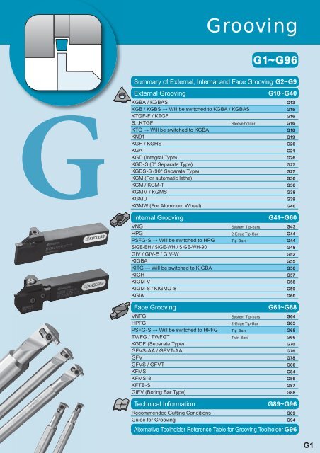
<strong>Grooving</strong>G1~G96Summary of <strong>External</strong>, Internal and Face <strong>Grooving</strong>G2~G9<strong>External</strong> <strong>Grooving</strong>KGBA / KGBASG13KGB / KGBS → Will be switched to KGBA / KGBASG15KTGF-F / KTGFG16S...KTGF Sleeve holder G16KTG → Will be switched to KGBAG18KN91G19KGH / KGHSG20KGAG21KGD (Integral Type)G26KGD-S (0° Separate Type)G27KGDS-S (90° Separate Type)G27KGM (For automatic lathe)G36KGM / KGM-TG36KGMM / KGMSG38KGMUG39KGMW (For Aluminum Wheel)G40Internal <strong>Grooving</strong> VNG System Tip-bars G43HPG 2-Edge Tip-Bar G44PSFG-S → Will be switched to HPG Tip-Bars G44SIGE-EH / SIGE-WH / SIGE-WH-90G48GIV / GIV-E / GIV-WG52KIGBAG55KITG → Will be switched to KIGBAG56KIGHG57KIGM-VG58KIGM-8 / KIGMU-8G59KGIAG60Face <strong>Grooving</strong>VNFG System Tip-bars G64HPFG 2-Edge Tip-Bar G65PSFG-S → Will be switched to HPFG Tip-Bars G65TWFG / TWFGT Twin Bars G66KGDF(Separate Type)G70GFVS-AA / GFVT-AAG76GFVG78GFVS / GFVTG80KFMSG84KFMS-8G86KFTB-SG87GIFV (Boring Bar Type)G88Technical InformationRecommended Cutting ConditionsGuide for <strong>Grooving</strong>G10~G40G41~G60G61~G88G89~G96G89G94Alternative Toolholder Reference Table for <strong>Grooving</strong> Toolholder G96G1
Summary of KGD Type <strong>Grooving</strong> <strong>External</strong> <strong>Grooving</strong> (G22~G31)Integral TypeTypeKGDWidth (mm) 2.0~8.0<strong>Grooving</strong> Depth (mm) 6~30Ref. PageG26GSeparate TypeTypeKGDS-SWidth (mm) 3.0<strong>Grooving</strong> Depth (mm) 10Ref. PageG27The separate type toolholders can accept allthe inserts if their hand is matching.<strong>Grooving</strong>Separate TypeTypeKGD-SWidth (mm) 2.0~5.0<strong>Grooving</strong> Depth (mm) 10~25Ref. PageG27The separate type toolholders can accept allthe inserts if their hand is matching.Low CuttingForceGSLow FeedGLFor generalpurposeGMHigh feed ratePHGeneral cut-offPMCopyingCM Face <strong>Grooving</strong> ø25~ (G68~G75)<strong>Grooving</strong> andLongitudinal turningGMDeep grooving andLongitudinal turningDMType* KGDFMin. Face Groove Dia. ø25Width (mm) 3.0~6.0<strong>Grooving</strong> Depth (mm) 13~32Ref. PageG70The separate type toolholders can accept allthe inserts if their hand is matching.G2
Summary of <strong>External</strong> <strong>Grooving</strong><strong>External</strong> <strong>Grooving</strong> & Longitudinal turning (G32~G39)CERACUT Plunge & TurnTypeKGMMWidth (mm) 3.0~5.0<strong>Grooving</strong> Depth (mm) 4.8Ref. Page G38KGMS3.0~5.04.8G38Molded ChipbreakerMolded ChipbreakerFull-RGround ChipbreakerG<strong>Grooving</strong>TypeKGMWidth (mm) 1.5~4.0<strong>Grooving</strong> Depth (mm) 5~16Ref. Page G36KGM3.0~8.09~25G36KGM-T2.0~6.017~30G37KGMU3.0~5.03.5~4.5G39Molded ChipbreakerMolded ChipbreakerFull-RGround ChipbreakerDeep <strong>Grooving</strong>/Cut-OffMolded ChipbreakerFull-RG4
Summary of Internal <strong>Grooving</strong>Small Dia. Internal <strong>Grooving</strong> ø4~ (G43~G45)2-Edge Tip-Bar & System Tip-BarTypeHPGMin.Bore Dia.ø4~ø7Width (mm) 1.0~2.0<strong>Grooving</strong> Depth (mm) 1.0~2.0Ref. PageG442-Edge Tip-BarGTypeVNGMin.Bore Dia.ø4~ø7Width (mm) 1.0~2.0<strong>Grooving</strong> Depth (mm) 0.8~2.0Ref. PageG43System Tip-bars<strong>Grooving</strong>Internal <strong>Grooving</strong> ø8~ (G46~G56) Shallow <strong>Grooving</strong>Type SIGEMin.Bore Dia. ø8~ø12Width (mm) 1.0~3.0<strong>Grooving</strong> Depth (mm) 1.5~2.2Ref. Page G482-EdgeGroundChipbreaker2-EdgeGround ChipbreakerFull-RType GIVMin.Bore Dia. ø12~ø40Width (mm) 1.0~5.0<strong>Grooving</strong> Depth (mm) 1.7~6.3Ref. Page G521-EdgeGroundChipbreaker2-EdgeGroundChipbreaker2-EdgeGround ChipbreakerFull-RType SIGEMin.Bore Dia. ø14~ø40Width (mm) 1.0~5.0<strong>Grooving</strong> Depth (mm) 2.5~6.5Ref. Page G482-Edge 2-Edge 2-EdgeMoldedChipbreakerGroundChipbreakerGround ChipbreakerFull-RType KIGBAMin.Bore Dia. ø35~ø40Width (mm) 0.33~4.8<strong>Grooving</strong> Depth (mm) 0.8~2.8Ref. Page G55GroundChipbreakerGround ChipbreakerFull-RMY ChipbreakerType KITGMin.Bore Dia. ø35~ø45Width (mm) 0.75~4.5<strong>Grooving</strong> Depth (mm) 2.0~2.5Ref. Page G56Ground Chipbreaker* KITG will beswitched to KIGBA.G6
Deep <strong>Grooving</strong>(G57, G60)TypeKGIAMin.Bore Dia.ø32~ø66Width (mm) 3.0~5.0<strong>Grooving</strong> Depth (mm) 10~15Ref. PageG60Molded ChipbreakerTypeKIGHMin.Bore Dia.ø45~ø65Width (mm) 4.0~8.0<strong>Grooving</strong> Depth (mm) 12Ref. PageG57Ground ChipbreakerGMolded ChipbreakerInternal <strong>Grooving</strong> & Longitudinal turning ø20~(G58, G59)CERACUT Plunge & Turn<strong>Grooving</strong>TypeKIGM-VMin.Bore Dia.ø20~ø40Width (mm) 3.0~5.0<strong>Grooving</strong> Depth (mm) 5.5~11.0Ref. PageG58Molded ChipbreakerMolded ChipbreakerTypeKIGM-8Min.Bore Dia.ø65Width (mm) 8.0<strong>Grooving</strong> Depth (mm) 20Ref. PageG59Molded ChipbreakerGround ChipbreakerTypeKIGMU-8Min.Bore Dia.ø65Width (mm) 8.0<strong>Grooving</strong> Depth (mm) 2.2Ref. PageG59Ground ChipbreakerFull-RG7
Summary of Face <strong>Grooving</strong> Micro Dia. Face <strong>Grooving</strong> ø6~TypeSTWMin. Face Groove Dia. ø6Width (mm) 0.5~2.0<strong>Grooving</strong> Depth (mm) 1.0~3.0Ref. PageG66TypeS..-STWMin. Face Groove Dia. ø6Width (mm) 0.5~2.0<strong>Grooving</strong> Depth (mm) 1.0~3.0Ref. PageG66Twin Bar for Lay-down typeG<strong>Grooving</strong>TypeSTWSMin. Face Groove Dia. ø6Width (mm) 0.5~2.0<strong>Grooving</strong> Depth (mm) 1.0~3.0Ref. PageG67Twin Bar for Stand up type Small Dia. Face <strong>Grooving</strong> ø8~TypeGFVS-AAMin. Face Groove Dia. ø8Width (mm) 1.0~3.0<strong>Grooving</strong> Depth (mm) 2.2Ref. PageG76TypeGFVT-AAMin. Face Groove Dia. ø8Width (mm) 1.0~3.0<strong>Grooving</strong> Depth (mm) 2.2Ref. PageG76Ground Chipbreaker Small Dia. Face <strong>Grooving</strong> ø8~TypeVNFGMin. Face Groove Dia. ø8Width (mm) 1.0~3.0<strong>Grooving</strong> Depth (mm) 2.0~3.0Ref. PageG64System Tip-barsTypeHPFGMin. Face Groove Dia. ø8Width (mm) 1.0~3.0<strong>Grooving</strong> Depth (mm) 2.0~3.0Ref. PageG652-Edge Tip-BarG8
General Purpose Face <strong>Grooving</strong> ø20~TypeGFVSMin. Face Groove Dia. ø35~ø150Width (mm) 2.5~6.0<strong>Grooving</strong> Depth (mm) 4.6~8.1Ref. PageG80Molded ChipbreakerTypeKFTBMin. Face Groove Dia. ø65~ø250Width (mm) 4.0~5.0<strong>Grooving</strong> Depth (mm) 25~38Ref. PageG87Ground ChipbreakerGGround ChipbreakerGround ChipbreakerFull-RTypeGFVMin. Face Groove Dia. ø20~ø150Width (mm) 2.0~6.0<strong>Grooving</strong> Depth (mm) 2.2~8.1Ref. PageG78Face <strong>Grooving</strong> & Longitudinal turning ø25~(CERACUT Plunge & Turn)Ground ChipbreakerFull-RTypeGFVTMin. Face Groove Dia. ø35~ø150Width (mm) 2.5~6.0<strong>Grooving</strong> Depth (mm) 4.6~8.1Ref. PageG80 Face <strong>Grooving</strong> ø35~<strong>Grooving</strong>TypeKFMSMin. Face Groove Dia. ø25~ø235Width (mm) 3.0~6.0<strong>Grooving</strong> Depth (mm) 13~32Ref. PageG84Molded ChipbreakerTypeKFMS-8Min. Face Groove Dia. ø54~ø155Width (mm) 8.0<strong>Grooving</strong> Depth (mm) 25Ref. PageG86TypeGIFVMin. Face Groove Dia. ø35~ø50Width (mm) 2.0~6.0<strong>Grooving</strong> Depth (mm) 2.2~8.1Ref. PageG88Molded Chipbreaker Ground Chipbreaker Ground ChipbreakerFull-RGround ChipbreakerGround ChipbreakerFull-RG9
<strong>Grooving</strong> InsertsG<strong>Grooving</strong> Applicable InsertsP Carbon steel / Alloy steel Classification of usageM Stainless Steel : Continuous-Light(mm) K Cast Iron Interruption / 1st ChoiceDescription A T ød N Non-ferrous Metals : Continuous-LightGBA32_ 9.525 3.18 4.4 S Titanium Alloy Interruption / 2nd ChoiceGBA43_ 12.70 4.76 5.5: Continuous / 1st ChoiceH Hard materials (~40HRC) : Continuous / 2nd ChoiceGBA43480 12.70 5.00 5.5 Hard materials (40HRC~)ShapeHanded Insert shows R-hand.ArεW±0.03Trε2゜ødBDescription(OldDescription)Dimension (mm)W B rεCermetTC40TN6020TN90PR1215MEGACOATPVD Coated CarbideApplicablePR1115PR905PR930PR630KW10GBA32 033-005 - 0.33 0.8 050-005 * GBA32 050 * 0.50 1.0 050-005 * - 0.50 1.2 075-005 GBA32 075 0.75 0.05095-005 095 0.95 100-005 100 1.00 110-005 110 1.10 2.0 120-005 120 1.20 125-020 125 1.25 130-020 130 1.30 140-020 140 1.40 2.5 145-020 145 1.45 2.0 145-020 - 1.45 2.5 150-020 GBA32 150 1.50 2.0 150-020 - 1.50 160-020 GBA32 160 1.60 2.5 0.2 170-020 170 1.70 175-020 GBA32 175 1.75 2.0 175-020 - 1.75 200-020 GBA32 200 2.00 225-020 225 2.25 2.5 250-020 250 2.50 300-020 300 3.00 GBA43 125-010 - 1.25 0.1 2.0125-020 GBA43 125 1.25 140-020 140 1.40 3.5 0.2 145-020 145 1.45 2.0 145-020 - 1.45 0.2 150-010 - 1.50 0.1 150-020 GBA43 150 1.50 170-020 170 1.70 175-020 175 1.75 0.2 185-020 185 1.85 3.5 195-020 195 1.95 200-010 - 2.00 0.1 200-020 GBA43 200 2.00 225-020 225 2.25 0.2 230-020 230 2.30 250-010 - 2.50 5.0 0.1 CarbideToolholdersKGBA…16KGBAS…16KGBA…22-15KGBAS…22-15KGBA…22-25T5KGBAS…22-25T5Ref. Page for ToolholderG13G15G55250-030 GBA43 250 2.50 4.0 KGBA…22-25KGBAS…22-25KGBA…22-25T5KGBAS…22-25T5250-030 - 2.50 5.0 0.3265-030 GBA43 265 2.65 4.0 KGBA…22-25T5KGBAS…22-25T5KGBA…22-25KGBAS…22-25KGBA…22-25T5KGBAS…22-25T5• Dimension B shows available grooving depth.* The edge width tolerance of GBA32R/L050 (with mark) is different (0.50 )• SeeG55 for KIGBA265-030 - 2.65 5.0 KGBA…22-25T5KGBAS…22-25T5Recommended Cutting ConditionsG89G10Inserts are sold in10 piece boxes. : Std. Item: Check Avaailability
<strong>Grooving</strong> Inserts Applicable InsertsApplicableP Carbon steel / Alloy steel Classification of usageM Stainless Steel : Continuous-Light(mm) K Cast Iron Interruption / 1st ChoiceDescription A T ød N Non-ferrous Metals : Continuous-LightGBA32_ 9.525 3.18 4.4 S Titanium Alloy Interruption / 2nd ChoiceGBA43_ 12.70 4.76 5.5: Continuous / 1st ChoiceH Hard materials (~40HRC) : Continuous / 2nd ChoiceGBA43480 12.70 5.00 5.5 Hard materials (40HRC~)Dimension (mm) CermetMEGACOATPVD Coated CarbideShapeHanded Insert shows R-hand.Description(OldDescription)W B rεTC40TN6020TN90PR1215PR1115PR905PR930PR630KW10ToolholdersGBA32 200-100R2.00 1.00 R R-KGBAR…162.5300-150R 3.00 1.50 R RKGBASL…16CarbideRef. Page for ToolholderGFull-RFull-R (Round)Arε±0.03W• Dimension B shows available grooving depth.• SeeG55 for KIGBAT2ødBGBA43 100-050R GBA43 050R 1.00 2.0 0.50 KGBA…22-15150-075R 075R 1.50 0.75 3.5KGBAS…22-15200-100R 100R 2.00 1.00 250-125R 125R 2.504.0300-150R 150R 3.00 1.50 1.25 KGBA…22-25KGBAS…22-25KGBA…22-25T5KGBAS…22-25T5400-200R 200R 4.00 5.0 2.00 KGBA…22-35KGBAS…22-35Recommended Cutting ConditionsG13G15G55G89<strong>Grooving</strong> Applicable InsertsP Carbon steel / Alloy steelClassification of usageM Stainless Steel: Continuous-Light(mm) K Cast IronInterruption / 1st ChoiceDescription A T ød N Non-ferrous Metals : Continuous-LightGBA32_ 9.525 3.18 4.4 S Titanium Alloy Interruption / 2nd ChoiceGBA43_ 12.70 4.76 5.5 Hard materials (~40HRC): Continuous / 1st ChoiceH : Continuous / 2nd ChoiceGBA43480 12.70 5.00 5.5 Hard materials (40HRC~) Dimension (mm) CBN PCDShapeHanded Insert shows R-hand.Description(OldDescription)W B rεApplicableToolholdersGBA32 125-010 GBA32 125 1.25R KGBAR…162.0 0.1150-010 150 1.50 R R KGBASL…16GBA43 125-010 GBA43 1250.1 1.25 2.0125-020 125 0.2 1-EdgeA rε rε150-010 1500.1 KGBA…22-151.50150-020 150 0.2 KGBAS…22-153.5T200-010 2000.1 2.00GBA32 S=1.7200-020 200 0.2 GBA43 S=1.9250-010 2500.1 2.50KGBA…22-25250-020 250 0.2 4.0KGBAS…22-25300-010 3000.1 KGBA…22-25T53.00KGBAS…22-25T5300-020 300 0.2 • Dimension B shows available grooving depth.• SeeG55 for KIGBARecommended Cutting ConditionsSW ±0.032BødKBN510KBN525KPD001KPD010Ref. Page for ToolholderG13G15G55G89MEGACOATPR1215 AdvantagesHigh reliability and long tool lifegrooving owing to micro-graincarbide substrate and MEGACOATtechnology Machining cost reduction at highspeed cutting by MEGACOATwith high hardness and oxidationresistanceSuitable for shallow grooving ofsteel and stainless steel Material Application MapSteel Stainless Steel Cast IronHighspeedMediumspeedLowspeedPR930PR1215PR1115Continuous Light interruption InterruptionApplicationHighspeedMediumspeedLowspeedPR1215PR1115Continuous Light interruption InterruptionApplicationHighspeedMediumspeedLowspeedPR905Continuous Light interruption InterruptionApplicationG12Inserts are sold in10 piece boxes.CBN & PCD Inserts are sold in1 piece boxes. : Std. ItemR : R-hand Only: Check Availability
<strong>External</strong> Shallow <strong>Grooving</strong> ToolholdersLever Lock KGBA• Right-hand shownR-hand Insert for R-hand Toolholder, L-hand Insert for L-hand Toolholder. KGBAS G• Right-hand shownL-hand Insert for R-hand Toolholder, R-hand Insert for L-hand Toolholder. Toolholder DimensionsDescriptionStd.Dimension (mm)R L H1=h H3 B L1 L2 F1 A TClamp SetSpare PartsWrenchApplicable InsertsG10~G12<strong>Grooving</strong>KGBA 1616H-16 16 16 100 202020K-16 20 4.0 20 125 24 252525M-16 25 25 150 30- 2.5 LGBA-16 S GBA32 type2020K22-15 20 20 125 25 4.0 25.52525M22-15 25 25 150 30 1.0 4.02020K22-25 20 20 125 25 4.0 25.52525M22-25 25 25 150 30 2.0 4.52020K22-25T5 20 20 125 25 FT-154.0 25.5 2.02525M22-25T5 25 25 150 30LGBA-22 S GBA43 type5.52020K22-35 20 20 125 25 4.0 25.5 3.02525M22-35 25 25 150 302020H22-15* 1.0 4.02020H22-25* 20 4.0 20 100 25.5 25 2.0 4.52020H22-35* 3.0 5.5KGBAS 2020K-16 20 4.0 20 125 25 252525M-16 25 4.5 25 150 30- 2.5 LGBA-16 SGBA32 type2020K22-15 20 4.5 20 125 27 252525M22-15 25 5.0 25 150 32 1.0 4.02020K22-25 20 4.5 20 125 27 25 2.0 4.5FT-152525M22-25 25 5.0 25 150 32LGBA-22 S GBA43 type2020K22-25T5 20 4.5 20 125 27 25 2.02525M22-25T5 25 5.0 25 150 325.52020K22-35 20 4.5 20 125 27 25 3.02525M22-35 25 5.0 25 150 32• Dimension T shows the distance from the Toolholder to the cutting edge. Dimension B shows available grooving depth.• Clamp Set :KGBA…LGBA-RS for R-hand Toolholder, and LGBA-LS for L-hand Toolholder.KGBAS…LGBA-LS for R-hand Toolholder, and LGBA-RS for L-hand Toolholder. Rake Angle (α) after Installment of GBAGBA32 GBA43 GBA43R(Full-R)α Insert Grades α Insert Grades α Insert Grades Full-R Description10°TN90,PR630,PR930PR1115,PR1215,PR905KPD001,KPD01020° KW100° KBN510, KBN52510°TC40N,TN90,PR630,PR93010° PR1115,PR1215,PR905KPD001, KPD010 14°20° KW10<strong>External</strong> <strong>Grooving</strong> Toolholders KGBA Short Shank types are availableTN90,PR630,PR930PR1115,PR1215,PR905TN90,PR630,PR930PR1115,PR1215,PR905050R~150RFor NC lathe and HSK tooling, KGBAR2020K-(Overall length 125mm) short shank type KGBAR2020H22-(Overall length 100mm) is available. No longer required for the users tocut the shank portion.KW10200R050R~200RRake Angle (α) afterInstallment of GBA-MYα*15°mark indicates short shank type.DescriptionGBA43175MY~GBA43350MY14° GBA43400MYα indicates the rake angle at the centerof the edge width, after installing insert.: Std. Item: Check AvailabilityG13
<strong>Grooving</strong> Inserts[GB insert changes toGBA (G10-G12).]G<strong>Grooving</strong> Applicable Inserts(mm)Description A TGB32_ 9.525 3.18GB43_ 12.70 4.76GB43480 12.70 5.00General (Square)(Corner is C shaped)GB32 typeGeneral (Square)(Corner is R shape)GB43 type1-EdgeInsertRight-hand ShownACWT0.03C2(Corner is C shape)ArWTB0.03r2GB type insert changes toGBA type when order isplaced.When replacing with GBAinsert, please consider theCorner-R(rε) specification.AAr1.9rW 0.03TWrB2B0.032DescriptionPMKNSHCarbon Steel / Alloy SteelStainless SteelCast IronNon-ferrous MetalsTitanium AlloyHard materials (under 40HRC)Hard materials (over 40HRC)Dimension (mm) Cermet PVDCoated CarbideBCorrεCarbideDiamondTC40TC60PR630PR930KW10KPD001KPD010GB32 050 * 0.50 1.0 C0.05 075 0.75095 0.95 100 1.00 2.0KGB125 1.25 C0.10KGBS145 1.45 150 1.50 200 2.002.5250 2.50 GB43 1250.1 1.25 2.0125 0.2 145 1.45 2.0 0.2 1500.1 1.50150 0.2 KGB175 1.75 0.2 KGBS185 1.85 3.5 0.2 2000.1 2.00200 0.2 230 2.30 0.2 2500.1 2.50250 0.3 265 2.65 0.3 KGB280 2.80 4.0 0.3 KGBS3000.1 3.00300 0.3 330 3.30 0.3 3500.1 3.50350 0.3 4000.1 4.00KGB400 5.0 0.4 KGBS430 4.30 0.4 450 4.50 0.4 480 4.80 0.4 GB43 125 1.25 2.0KGB150 1.503.5KGBS200 2.00 0.1250 2.50 KGB4.0300 3.00 KGBSGB43 050R 1.00 2.0 0.50 075R 1.500.75 3.5100R 2.00 1.00 Classification of usage: Continuous-Light Interruption / 1st Choice: Continuous-Light Interruption / 2nd Choice : Continuous / 1st Choice : Continuous / 2nd ChoiceApplicableToolholderKGBKGBS161622-1522-1522-2522-2522-3522-3522-1522-1522-2522-2522-1522-15Ref.Page forToolholderG15Full-RTB125R 2.501.25 4.0150R 3.00 1.50 KGBKGBS22-2522-25200R 4.00 5.0 2.00 KGBKGBS22-3522-35• Dimension B shows available grooving depth.The edge width tolerance of GB32050 is different.0.50 +0.05−0(*)* Material selection standard when changing to GBA.GB InsertTC40TC60PR630PR930KPD010GBA InsertTC40TN90PR1215/PR1115PR1215/PR1115KPD001 (KPD010)* Check the cornner-R(rε) of the insert when changing.For recommended cutting conditions, see pageG89G14Inserts are soldin 10 piece boxes.CBN & PCD Inserts are soldin 1 piece boxes.Check Availability
<strong>External</strong> Shallow <strong>Grooving</strong> Toolholders [for GB / GBA Insert]Top ClampKGB (Changes to KGBA G13)T2AhF1L22L1H1 H3 B● Right-hand shownR-hand insert for R-hand toolholder, L-hand insert for L-hand toolholder.KGBS (Changes to KGBAS G13)2hF1AL2TL1H1 H3 BG2 Toolholder DimensionsDescription● Right-hand shownStd.Dimension (mm)RL H1=h H3 B L1 L2 F1 A TL-hand insert for R-hand toolholder, R-hand insert for L-hand toolholder.Spare PartsClamp Clamp Bolt Spring WrenchApplicableInsertsG10G12G14<strong>Grooving</strong>KGB 2020K-16 20 20 125 2511242525M-16 25 25 150 302020K22-15 20 20 125 2511.5 25.52525M22-15 25 25 150 302020K22-25 20 20 125 2511.5 25.52525M22-25 25 25 150 302020K22-35 20 20 125 2511.5 25.52525M22-35 25 25 150 30KGBS 2020K-16 20 20 125 2511252525M-16 25 25 150 302020K22-15 20 20 125 2711.5 252525M22-15 25 25 150 322020K22-25 20 20 125 2711.5 252525M22-25 25 25 150 322020K22-35 20 20 125 2711.5 252525M22-35 25 25 150 32• Dimension T shows the distance from the Toolholder to the cutting edge. Dimension B shows available grooving depth.Clamp: KGB ... CGBR for Right-hand Toolholder, and CGBL for Left-hand Toolholder.KGBS ... CGBR for Right-hand Toolholder, and CGBL for Left-hand Toolholder. Rake Angle (α) after Installment of GBAGB32 GB43 GBA43 R (Full-R)α Insert Grades α Insert Grades α Insert Grades5°TC60PR63020° KW105°TC40 TC60PR630 PR93010° KPD01020° KW105°14°TC60PR630- 2.51.0 4.02.0 4.53.0 5.5- 2.51.0 4.02.0 4.53.0 5.5050R~150RTC60PR630200RKW10…050R~200RCGB BH6X25 SP-6 LW-4CGB BH6X25 SP-6 LW-4ClampKGB ToolholderGB32GBA32GB43GBA43GB32GBA32GB43GBA43KGBA Toolholder* KGB / KGBS toolholder changes to KGBA / KGBAS.Better Chip flow.*For applicable insert, GB insert changes to GBA. There arevarious types of GBA insert materials available depending on theuser's cutting condition requirements.: Std. ItemCheck AvailabilityG15
<strong>External</strong> Shallow <strong>Grooving</strong> Toolholders [for TGF Insert] KTGF-F(Without Offset)2F12h(2.5) * Clamp Screw can also be operated from this side.L2L1H1 H3 BScrew Clamp Usage differencebetween KTGF-F andKTGF toolholdersIt is necessary to use“Without Offset Type” inoperating the automatic lathe.Dimension F1● Right-hand shownH2R-hand insert for R-hand toolholder, L-hand insert for L-hand toolholder. KTGF(With Offset)(2.5)No gap Dimension BWithout Offset Type (KTGF-F)Dimension F1G2F1hL22L1H1 H3 B<strong>Grooving</strong>● Right-hand shown Toolholder DimensionsH2R-hand insert for R-hand toolholder, L-hand insert for L-hand toolholder.DescriptionStd. Dimension (mm) Spare PartsRL H1=h H2 H3 B L1 L2 F1 Clamp Screw WrenchKTGF 1010JX-16F 10 2 10101212JX-16F 12 2.5 12 120 18.5 12 SB-4070TRW FT-8-1616JX-16F 16 16 16KTGF 1212F-16F 12 - 2.5 12 85 18.5 12 SB-4070TRW FT-8KTGF 1010F-16 10 4 10 80 121212H-16 12 2 12 100 18.5 161616H-16 16 2.5 16 100 20 SB-4070TRS FT-102020K-16 20 - 20 125 25 202525M-16 25 25 150 32LargegapDimension BWith Offset Type (KTGF)Remarksα Insert GradesTN90, TC6020° PR1115, PR930, KW1011° KPD010, KPD0016° TC40 S-KTGF(Sleeve Holder)212 Toolholder Dimensions● Left-hand shownDescription Std.Dimension (mm)øD L1 F1 F2 ød1 ød2 H1=H2S12F-KTGFL16 12.0 8011.011S14H-KTGFL16 14.0 100 13.0 139.0S15F-KTGFL16 15.87585 14.6 15S16F-KTGFL16 16.0627S19G-KTGFL16 9019.05 10.5 17.6 17S19K-KTGFL16 120S20G-KTGFL16 9020.0S20K-KTGFL16 12011.0 18.6 18S25.0H-KTGFL16 25.0 100S25K-KTGFL16 25.4 12010 14.0 23.6 32 23d25F2 F12Note 12.520d1L1DH2H1α Insert GradesTN90, TC6020° PR1115, PR930, KW1011° KPD010, KPD0016° TC40R-hand Insert for L-hand Toolholder.Note 1. Dimension B shows available grooving depth.Spare PartsClamp Screw WrenchSB-4070TRSFT-10G16: Std. Item: Check Availability
Screw ClampApplicable InsertsP Carbon Steel / Alloy Steel(mm) M Stainless SteelDescription A T ød K Cast IronTGF32_ 9.525 3.18 4.5 N Non-ferrous Metals S Titanium Alloy TGF32325 9.525 3.40 4.5Hard materials (under 40HRC) TGF32315-SRC 9.525 3.40 4.5 HHard materials (over 40HRC)PVDDimension (mm) CermetCoated CarbideCarbide PCDInsertDescriptionC B orR-hand shownrεTGF32033 0.33 0.8R 050 0.50 C0.05 1.2060 0.60 075 0.75 080 0.80 090 0.90 095 0.95 100 1.00 120 1.20 125 1.25 2.0 130 1.30 140 1.40 C0.1145 1.45 150 1.50 170 1.70 175 1.75 General (Square)(Corner is C shaped)185 1.85190 1.90 200 2.00 2.5 225 2.25 250 2.50 TGF32 275 2.75AW0.03 rCr300 3.00 3.0 0.2 C325 3.25 TGF32033-005 0.33 0.8R R R0.05050-005 0.50 1.2 RT075-010 0.75 R095-010 0.95 R100-010 1.00 RGeneral (Square)120-010 1.20 (Corner is R shaped)125-010 1.25 2.0 R140-010 1.40 0.1145-010 1.45 R150-010 1.50 RTGF32175-010 1.75 R - 200-010 2.00 R2.5250-010 2.50 RTGF32$S-S type TGF32$S090-S 0.90Edge Width Tolerance110-S 1.10 2.0W 130-S 1.30 +0.12 +0.06C0.05 160-S 1.60 185-S 1.85 2.5 1-EdgeTGF32$S-SRGtypeEdge Width ToleranceW +0 -0.05For Circlip Grooves(DIN 471 / 472)A W0.03C CS125~150 S=1.7200 S=1.9T2d2dBBTGF32$S080-SRG 0.87090-SRG 0.97100-SRG 1.072.0110-SRG 1.24rε130-SRG 1.44max160-SRG 1.740.03185-SRG 1.99 2.5215-SRG 2.29265-SRG 2.79 3.0315-SRG 3.29TN60TN90TC40TC60PR630PR930PR1115KW10KPD001KPD010TGF32125 1.25 2.0150 1.50 C0.1 200 2.00 2.5 TGF32125-010 1.25R2.0150-010 1.50 0.1R200-010 2.00 2.5 RClassification of usage: Continuous-LightInterruption / 1st Choice: Continuous-LightInterruption / 2nd Choice : Continuous / 1st Choice : Continuous / 2nd ChoiceApplicableToolholderKTGF…16FKTGF…16S…KTGFL16Ref.Page forToolholder• Dimension B shows available grooving depth. For recommended cutting conditions, see page G90G16G<strong>Grooving</strong>Inserts are soldin 10 piece boxes.CBN & PCD Inserts are soldin 1 piece boxes.: Std. Item: Check AvailabilityR : Std. Item (R-hand Only) L : Std. Item (L-hand Only)G17
<strong>External</strong> Shallow <strong>Grooving</strong> Toolholders [TG Insert]Screw ClampKTG (Changes to KGBA G13)TF1AhWBLLH1 H3● Right-hand shownR-hand insert for R-hand toolholder, L-hand insert for L-hand toolholder. Toolholder DimensionsDescriptionStd.Dimension (mm)RL H1=h H3 B L1 L2 F1 A TClamp ScrewSpare PartsWrenchG<strong>Grooving</strong>KTG 2020K-16 20 20 125 253.0 202525M-16 25 25 150 30- 2.5 SB-4TR - FT-15 -2020K22-15 20 20 125 25 3.0 252525M22-15 25 25 150 30 1.0 4.02020K22-25 20 20 125 25 3.0 25 2.0 4.52525M22-25 25 25 150 30- GS-50 - LW-32020K22-35 20 20 125 25 3.0 252525M22-35 25 25 150 30 3.0 5.5• Dimension T shows the distance from the Toolholder to the cutting edge. Dimension B shows available grooving depth.* GBA Insert cannot be installed to this toolholder.Applicable Inserts(TG insert changes to GBA G10~ G12)Description A T ødTG32_ 9.525 3.18 4.5TG43_ 12.70 4.76 5.5General (Square)(Corner is C shape)TG32 typeGeneral (Square)(Corner is R shape)TG43 typeInsertR-hand shown• Dimension B shows available grooving depth.ACW0.03CTB(Corner is C shape)AdW0.03TBd(mm)* KTG will be switched to KGBA.Machining against the wall is available.* For applicable insert, TG insert changes to GBA.Change Insert Grade TN60 for TN90.There are various types of GBA insert materials available depending on the user’scutting condition requirements.* Check the cornner-R(rε) of the insert when changing.DescriptionPMKNSHCarbon Steel / Alloy SteelStainless SteelCast IronNon-ferrous MetalsTitanium AlloyHard materials (under 40HRC)Hard materials (over 40HRC)Dimension (mm)BCorrεCermetTN60TN90TC40TC60Classification of usage: Continuous-Light Interruption / 1st Choice: Continuous-Light Interruption / 2nd Choice : Continuous / 1st Choice : Continuous / 2nd ChoiceApplicable ToolholderTG32 0750950.750.95125 1.25 145 1.45 2.0 C0.1 KTG…16150 1.50 175 1.75 200 2.00 TG43 150 1.50175 1.75 3.5 0.2200 2.00 KTG…22-15230 2.30 250 2.50265 2.65 280 2.80 4.0 0.3300 3.00 KTG…22-25330 3.30 350 3.50400 4.005.0430 4.30 0.4 KTG…22-35450 4.50 For recommended cutting conditions, see pageRef.Page forToolholderG18G18G90KTGKGBAG18: Std. Item: Check Availability R : Std. Item (R-hand Only) L : Std. Item (L-hand Only)Inserts are soldin 10 piece boxes.
<strong>External</strong> Shallow <strong>Grooving</strong> Toolholders[Ceramic TG Insert] KN91TAL2L1H3F1B● Right-hand shownhH1 Toolholder DimensionsDescriptionStd.Dimension (mm)RL H1=h H3 B L1 L2 F1 A TSpare PartsClamp Clamp Bolt Washer Spring WrenchKN91 44-4 40 22.5 3.4 15CE-111 / 121 44-5 25 16 25 150 42 22.5 4.4 17BH8X30 W-8 SP-8 LW-544-7 42 21 6.4 17 CE-131 / 141• Dimension T shows available grooving depth.Clamp: KN91 44-4 / 5 ... CE-111 for Right-hand Toolholder, and CE-121 for Left-hand Toolholder.KN91 44-7 ... CE-131 for Right-hand Toolholder, and CE-141 for Left-hand Toolholder.G Applicable Inserts(mm)Description L HGS91-4 12 5.0GS91-5~GS91-8 15 7.5Insert Recommended Cutting ConditionsL3W0.05120HDescriptionP Carbon Steel / Alloy SteelM Stainless SteelK Cast Iron N Non-ferrous MetalsS Titanium AlloyHHard materials (under 40HRC)Hard materials (over 40HRC) Dimension (mm)rεCeramicA65GS 91-4 4.00.591-5 5.0 91-6 6.091-7 7.0 0.891-8 8.0 PVDCeramicA66NClassification of usage: Continuous-Light Interruption / 1st Choice: Continuous-Light Interruption / 2nd Choice : Continuous / 1st Choice : Continuous / 2nd ChoiceApplicable ToolholderKN91…4KN91…5KN91…7Ref.Page forToolholderG19<strong>Grooving</strong>WorkpieceMaterialCast Iron (FC / FCD, etc.)Hard MaterialsRecommended Insert Grade(Cutting Speed m/min)CeramicA65GS91-4GS91-5GS91-6f (mm/rev)GS91-7GS91-8150~3000.03~0.07 0.04~0.0840~800.02~0.05 0.04~0.07 : 1st Recommendation: Std. Item: Check Availability R : Std. Item (R-hand Only) L : Std. Item (L-hand Only)Inserts are soldin 10 piece boxes.G19
<strong>External</strong> Shallow <strong>Grooving</strong> Toolholders[GH / GHU / GA Insert]Top Clamp KGHTTAF1h5L235H2BH1 H3AF1h5L2L1H1 H3 B● Right-hand shownKGH2020KKGH2525MKGH3225P KGHSG<strong>Grooving</strong> Toolholder DimensionsDescriptionhF1L2ATBF1KGHS2020K● Right-hand shownH2H1hStd.Dimension (mm)RL H1=h H2 H3 B L1 L2 F1 A TATL2L1H1 H3 BKGHS2525MSpare PartsClamp Clamp Bolt Washer Spring WrenchKGH 3.4 13 CGH-12020K-4 20 5 20 125 24.5-24.8 15.6 33.52525M-4 25 - 25 150 24.5-24.82020K-5 20 5 20 125 25.0-25.82525M-5 25 - 15.6 25 150 33.5 25.0-25.8 4.2 13 CGH-13225P-5 32 - 25 170 25.0-25.8HH6X25 W-6 SP-6 LW-52020K-7 20 5 20 125 24.5-25.0 15.6 33.5 5.82525M-7 25 - 25 150 24.5-25.0 13 CGH-22525M-10 25 -16.1 25 150 41 25.5-26.5 9.03225P-10 32 - 25 170 25.5-26.517 CGH-3KGHS 2020K-4 20 5 20 125 3515.6 252525M-4 25 - 25 150 403.4 13 CGH-1 L /R2020K-5 20 5 20 125 3515.6 252525M-5 25 - 25 150 404.2 13 CGH-1 L /R2525M-7 25 - 15.6 25 150 25 40 5.8 13 CGH-2 L /R• Dimension T shows available grooving depth.• Dimension F1 of KGH Toolholder depends on the insert's edge width.• Clamp: KGH ... CGH- R for Right-hand Toolholder, and CGH- L for Left-hand Toolholder.KGHS ... CGH- L for Right-hand Toolholder, and CGH- R for Left-hand Toolholder. Rake Angle (α) after Installment of GH / GHU insertGH - GHU α Insert Grades α Insert Grades0° A65, A66N10° TC40TN60TN90, TC60 10°CR902520° PR630, PR930KW10HH6X25 W-6 SP-6 LW-5G20: Std. Item: Check Availability
Top Clamp KGAF1TBAL2L1● Right-hand shown25hH2H1 H3 Toolholder DimensionsDescriptionStd.Dimension (mm)RL H1=h H2 H3 B L1 L2 F1 A TSpare PartsClamp Clamp Bolt Spring WrenchKGA 2020K -3 20 5 20 125 21.5637 2.3 20 CGA-32525M-3 25 - 25 150 26.52020K -4 20 5 20 125 21.5637 3.3 20 CGA-42525M-4 25 - 25 150 26.5HH6X20 SP-6 LW-5642 4.32020K -52525M-5 20 255-20 12525 15021.526.5 25 CGA-5KGA$ 2020K -3S 20 5 20 125 21.5634 2.32525M-3S 25 - 25 150 26.5 16 CGA-3$2020K -4S 20 5 20 125 21.5634 3.32525M-4S 25 - 25 150 26.5 16 CGA-4$HH6X20 SP-6 LW-5• Dimension T shows available grooving depth.• Clamp: CGA- R for Right-hand Toolholder, and CGA- L for Left-hand Toolholder. Applicable InsertsDescription L HGH4020- ~GH8020- 20GH10025-05~GH12025-05 25GHU 20GA30, GA40 25GA50 30GroundChipbreakerCeramicMolded ChipbreakerInsertW0.053W0.0533W0.05333105 W 0.055555LL6HHCeramic insertis above shape.LLH1201201207.55.0(mm)DescriptionP Carbon Steel / Alloy SteelClassification of usageM Stainless SteelK Cast Iron : Continuous-Light Interruption / 1st ChoiceN Non-ferrous Metals: Continuous-Light Interruption / 2nd ChoiceS Titanium Alloy : Continuous / 1st ChoiceHard materials (under 40HRC) H : Continuous / 2nd ChoiceHard materials (over 40HRC)Dimension (mm)rεCermetCVDCoated CarbidePVDCoated CarbideCarbideCeramicTN60TN90TC40TC60CR9025PR630PR930KW10A65A66NPT600MApplicableToolholderGH 4020-020.2 4.04020-05 0.5 4520-020.2 4.54520-05 0.5 KGH …4KGHS …45020-020.2 5.05020-05 0.5 5520-020.2 5.55520-05 0.5 KGH …56020-020.2 6.06020-05 0.5 KGHS …56520-020.2 6.56520-05 0.5 7020-020.2 7.07020-05 0.5 7520-020.2 KGH …77.57520-05 0.5 KGHS …78020-020.2 8.08020-05 0.5 10025-05 10.0 0.5 12025-05 12.0 0.5 KGH …10GHU 4020 4.0 0.25 KGH …4KGHS …45020 5.0 0.30 KGH …5KGHS …56020 6.0 0.30 GA 30 3.0 0.20 KGA …340 4.0 0.25 KGA …4Ref.Page forToolholderG20G20G21G<strong>Grooving</strong>H12050 5.0 0.30 KGA …5For recommended cutting conditions, see page G90~G91: Std. Item: Check Availability R : Std. Item (R-hand Only) L : Std. Item (L-hand Only)Inserts are soldin 10 piece boxes.G21
Summary of KGD <strong>Grooving</strong>Features1 Various insert lineupG Smooth chip control Newly-introduced chipbreakers designed to cover a variety of workpiece materials. High precision edge preparation High precision molding technology with tolerance ±0.03 mm (Edge width 2, 3, 4 mm types) Highly-reputed MEGACOAT technology Long tool life and high effi ciency machining achieved by superior oxidationresistance and wear resistance. Application Map Chipbreaker Selection<strong>Grooving</strong><strong>Grooving</strong> and Longitudinal turningHighCutting ResistanceLowHighCutting ResistanceSmallLowSmallLowFeedGLFor generalpurposeGMLow cuttingforceGSFeed RateCut-OffFor generalpurposePMFeed RateHigh feed ratePHLargeHighfeedratePHLargeNon-ferrousMetalsLow rigidmaterialGSApplication<strong>External</strong> <strong>Grooving</strong> Cut-Off CopyingLow FeedGLCarbon SteelAlloy SteelStainless SteelGMHigh feed rateInterruptionPHContinuousLow cutting force Low Feed General grooving High feed rate General cut-off CopyingPMCM Comparison of Chip Control(SCM415 Vc=150m/min, f=0.15mm/rev)GM Chipbreaker Competitor A Competitor BSmooth chip controlLess chip biting troublesFeatures of MEGACOATHardnessGPa40TiC30TiCN20TiNMEGACOATTiAlN100 200 400 600 800 1000 1200Oxidation onset temperature Wear Resistance ComparisonFrank wear (mm)0.200.150.100.05Cutting Conditions SNCM439, wetVc=200m/min,ap=2.0mmf=0.1mm/revCompetitor E0.000 20 40 60 80 100Cutting Time (min)Competitor CCompetitor DPR1215PR1225:1st choice for cut-off, grooving andLongitudinal turningPR1215:With superior wear resistance,recommended for grooving and cut-offunder the stable conditions as well asmachining of cast iron.G22
2 ToolholderIntegral type and separate type (toolholder + blade) are available.Integral TypeSeparate typeHigh rigidity separate typetoolholder Adaptable to wide applications bychanging bladesDeals with various edge widths and cuttingdepths by changing the blade and toolholdercombination.Even if the blade is broken, you only need toreplace the broken part.BladeSerrationToolholderG<strong>Grooving</strong>Structure of toolholder unit (Toolholder + Blade)(0° separate type)(90° separate type)Insert clamp boltBladeToolholderToolholderBlade fi xing boltBladeNote for the toolholder and blade combinationof 0° separate typeToolholderKGD-CBladeKGD-T-CR-hand Blade for R-hand Toolholder,L-hand Blade for L-hand Toolholder.Note for the toolholder and blade combinationof 90° separate typeToolholderKGDS-CBladeKGD -T-C L-hand Blade for R-hand Toolholder,R-hand Blade for L-hand Toolholder.G23
Inserts for <strong>Grooving</strong> and Cut-offG<strong>Grooving</strong><strong>Grooving</strong> and Traversing<strong>Grooving</strong>Full-R / Copying<strong>Grooving</strong> and Cut-OffShapeHanded insert shows R-hand.For general purpose2-EdgeLow Feed2-EdgeForgeneralpurpose1-EdgeLow cutting force2-Edge2-EdgeHigh feed rate2-EdgeHigh feed rate1-EdgeW2° W 2°1.5°1.5°2°W2°20°WW±0.031.5°1.5°MLMMMMLMLLLLMLrεrεrεHH 2° 2°Wrεrε1.5°HrεHHrε1.5°HHW±0.03Classification of usageContinuous-Light Interruption / 1st ChoiceContinuous-Light Interruption / 2nd ChoiceContinuous / 1st ChoiceContinuous / 2nd ChoiceP Carbon steel / Alloy steel M Stainless SteelK Cast IronN Non-ferrous MetalsS Titanium AlloyHHard Materials ( 40HRC)Hard Materials (40HRC )Dimension (mm)AngleCermet MEGACOAT Carbide°DescriptionWrε M L H θtoleranceGDM 2420N-020GM 2.4 0.2 1.95 3020N-020GM 0.2 3.0 2.33020N-040GM 0.4 ±0.034020N-020GM0.2 4020N-040GM 4.0 0.4 3.3 20 4.34020N-080GM 0.8 - 5020N-040GM 0.4 5.0 4.25020N-080GM 0.8 ±0.046020N-040GM 0.4 6.0 5.26020N-080GM 0.8 8030N-080GM 8.0 ±0.05 0.8 6.0 30 5.5 GDMS 2220N-020GM 2.2 0.2 1.75 3020N-040GM 3.0 ±0.03 0.4 2.3 4020N-040GM 4.0 0.4 3.3 20 4.3 - 5020N-080GM 5.0 0.8 4.2 ±0.046020N-080GM 6.0 0.8 5.2 GDM 2420N-020GL 2.4 0.2 1.95 3020N-020GL 0.2 3.0 2.33020N-040GL ±0.03 0.4 4020N-020GL 0.2 20 4.3 - 4.0 3.34020N-040GL 0.4 5020N-040GL 5.0 0.4 4.2 ±0.046020N-040GL 6.0 0.4 5.2 GDG 2520N-020GS 2.5 2.0 3020N-020GS 3.0 0.2 2.3 3520N-020GS 3.5 2.8 20 4.34020N-040GS 4.0 ±0.02 3.3 - 5020N-040GS 5.0 4.2 0.46020N-040GS 6.0 5.2 8030N-040GS 8.0 6.0 30 5.5 GDM 3020N-150R-CM 3.0 1.5 2.3 ±0.034020N-200R-CM 4.0 2.0 3.3 20 4.3 -5020N-250R-CM 5.0 2.5 4.2 ±0.046020N-300R-CM 6.0 3.0 5.2 GDM 2020N-020PH 2.0 0.2 1.5 3020N-030PH 3.0 ±0.03 0.3 2.3 20 - 4020N-030PH 4.0 0.3 3.3 4.3GDMS 2020N-020PH 2.0 0.2 1.5 3020N-030PH 3.0 ±0.03 0.3 2.3 20 - 4020N-030PH 4.0 0.3 3.3 TN90PR1225PR1215GW15Recommended Cutting ConditionsRef. Page for ToolholderG26G27G28G29Note for the holder and insert combination of KGD type (new) and KGM type (conventional)Insert setting angle for grooving toolholdersConventional tools New InsertGDMConventional InsertGMM0° 5°ConventionalNew ToolholderToolholderKGDKGMInstalling conventional inserts to the new toolholder is not recommended.G24Std. Item
Cut-OffShapeHanded insert shows R-hand.2-Edge2-EdgeW±0.033° 3°W±0.033° 3°MLMMLLθHrεrεrεH3° 3°W±0.03rεClassification of usageContinuous-Light Interruption / 1st ChoiceContinuous-Light Interruption / 2nd ChoiceContinuous / 1st ChoiceContinuous / 2nd ChoiceDescriptionWCarbon steel / Alloy steelStainless SteelCast IronNon-ferrous MetalsTitanium AlloyHard Materials ( 40HRC)Hard Materials (40HRC )Dimension (mm)tolerancerε M L H θAngleCermet MEGACOAT Carbide°GDM 2020N-020PM 2.0 0.2 1.5 2520N-020PM 2.5 0.2 1.95 ±0.0320 -3020N-025PM 3.0 0.25 2.3 4020N-030PM 4.0 0.3 3.3 GDM 2020R-020PM-6D 2.0 0.2 1.5 2520R-020PM-6D 2.5 ±0.03 0.2 1.95 20 6° 3020R-025PM-6D 3.0 0.25 2.3 4.3GDMS 2020N-020PM 2.0 0.2 1.5 3020N-025PM 3.0 ±0.03 0.25 2.3 20 - TN90PR1225PR1215GW15Ref. Page for ToolholderG26G27G28G1-EdgeMLθH3° 3°W±0.03rε4020N-030PM 4.0 0.3 3.3 GDMS 2020R-020PM-6D 2.0 0.2 1.5 3020R-025PM-6D 3.0 ±0.03 0.25 2.3 20 6° <strong>Grooving</strong>1-EdgeNote) 1. Using the PM chipbreaker (for cut-off) for grooving cannot create a flat bottom(See the right figure). Indication of DescriptionHTolerance SymbolM Class MG Class G4020R-030PM-6D 4.0 0.3 3.3 Width202mm303mm404mmHand of ToolRR-handLL-handNNeutralGroove bottom created byPM chipbreakerRecommendedCutting Conditions G29Chipbreaker symbolGM<strong>Grooving</strong> and TraversingGLLow FeedCMCopyingG D M S 30 20 N - 025 GM -6DSeriesNo. of cornersWithout Indication2-EdgeS1-EdgeSetting the insertsInsert Length2020mm3030mmCorner-Rrε0.200.2mm0.400.4mm150R1.5mmFull-RLead Angle6D6°1 Use compressed air or other measures to remove chips from the insert mounting part see (Fig. 1. 2Put the insert into the holder and push it until it makes contact with the back end of the holder’s surface (see Fig. 2 and 3). 3 Keeping the insert fi t to the surface, tighten the insert clamp bolt at an appropriate torque. 4Make sure that there is no gap between the insert and the back end of the holder’s surface and that the insert is set straight.Insert clamp boltRecommended tightening torque : 6.5Nm(Width 26mm)8.0Nm(Width 8mm)Insert mounting partHolder’s surface for fi xingthe inserts back endStd. ItemFig. 1 Fig. 2 Fig. 3G25
Toolholders for <strong>Grooving</strong> and Cut-offIntegral TypeF1WTBAhL2L3H2 H3L1H1R-hand ShownToolholder DimensionsGWidth mmMax. depth of cut (mm)DescriptionStd.DimensionmmWidthWmmR L H1=h H2 H3 B L1 L2 L3 F1 A T MIN MAXClamp BoltSpare PartsWrench<strong>Grooving</strong>234566KGD 1616H-2T06 16 4.0 16 100 27.7 28.0 15.2HH5X162020K-2T06 2020 125 28.0 19.2 6--2525M-2T06 25 25 150 28.0 24.2 HH5X2510KGD 1616H-2T10 16 4.0 16 100 30.2 30.5 15.2HH5X162020K-2T10 2020 125 30.5 19.2 10-- 1.7 2.0 3.0LW-42525M-2T10 25 25 150 30.5 24.2 HH5X25KGD 1616H-2T17 16 4.0 16 100 31.2 31.5 15.2172012K-2T17 12 12511.2HH5X1620 172020K-2T17 - 20 125 32.5 - 19.22525M-2T17 25 25 150 24.2 HH5X256KGD 1616H-3T06 16 4.0 16 100 27.7 28.0 14.8HH5X162020K-3T06 2020 125 28.0 18.8 6--2525M-3T06 25 25 150 28.0 23.8 HH5X2510KGD 1616H-3T10 16 4.0 16 100 30.2 30.5 14.8HH5X162020K-3T10 2020 125 18.8 10-30.5 - 2.4 3.0 4.0LW-42525M-3T10 25 25 150 23.8 HH5X25KGD 1616H-3T20 16 4.0 16 100 34.2 34.5 14.89.52012K-3T20 12 125 10.82020 34.5 202020K-3T20 - 20 125 - 18.8HH5X162525M-3T20 25 25 150 35.5 23.8 HH5X2510KGD 2020K-4T10 2020 125 18.3HH5X1630.5 102525M-4T10 25 25 150 23.3 HH5X25-- 3.4 4.0 5.0LW-420 KGD 2020K-4T20 20 20 125 34.5 18.3 HH5X16202525M-4T20 25 25 150 35.5 23.3HH5X2525 KGD 2525M-4T25 25 25 150 40.5 23.3 2510KGD 2020K-5T10 2020 125 17.8HH5X1630.5 102525M-5T10 25 25 150 22.817KGD 2020K-5T17 20 - 20 125 - 17.8 4.4 5.0 6.0LW-437.5 17HH5X252525M-5T17 25 25 150 22.825 KGD 2525M-5T25 25 25 150 40.5 22.8 2515 KGD 2525M-6T15 2525 150 32.5 22.4 15-- 5.3 6.0 6.0 HH5X25 LW-430 KGD 2525M-6T30 25 25 150 45.5 22.4 30G268 25 KGD 2525M-8T25 25 7.0 25 150 43.3 44.2 22.0 6.0 25 8.0 8.0 HH6X25 LW-53232P-8T25 32 - 32 170 - 29.0Note1. Dimension T: Maximum depth to which processing can be made. (If the dimension T is 20 mm or more, the maximum depth of groove made by the 2-edgeinsert will be 18 mm.)Std. Item Check Availability
(0° separate type)ThWF1BL2H1H3R-hand ShownAH2L1(90° separate type)BL3TGL2L1R-hand ShownhAH2 H3H1<strong>Grooving</strong>Toolholder DimensionsToolholderBladeShank Angle0°WidthMax. depth of cut(mm)Unit Description(Standard StockDescription)Std.ToolholderDescriptionG28BladeDescriptionG28Dimension mmWidthWmmR L H1=h H2 H3 B L1 L2 L3 F1 A T MIN MAX2 17 KGD 2020X-2T17S KGD2020-C KGD-2T17-C 20 12 20 122 23.439.92525X-2T17S KGD2525-C 25 7 25 147 28.4KGD 2020X-3T10S KGD2020-C20 12 20 11523.0102525X-3T10S KGD2525-C KGD-3T10-C 25 7 25 140 32.9 28.033232X-3T10S KGD3232-C 32 - 32 160 33.0KGD 2020X-3T20S KGD2020-C20 12 20 12523.0202525X-3T20S KGD2525-C KGD-3T20-C 25 7 25 150 42.9 28.03232X-3T20S KGD3232-C 32 - 32 170 33.0KGD 2020X-4T10S KGD2020-C20 12 20 11522.5102525X-4T10S KGD2525-C KGD-4T10-C 25 7 25 140 32.9 27.53232X-4T10S KGD3232-C 32 - 32 160 32.5KGD 2020X-4T20S KGD2020-C20 12 20 125 - 22.54 202525X-4T20S KGD2525-C KGD-4T20-C 25 7 11.6 25 150 42.9 27.53232X-4T20S KGD3232-C 32 - 32 170 32.5KGD 2020X-4T25S KGD2020-C20 12 20 13022.5252525X-4T25S KGD2525-C KGD-4T25-C 25 7 25 155 47.9 27.53232X-4T25S KGD3232-C 32 - 32 175 32.5KGD 2020X-5T10S KGD2020-C20 12 20 11522.0102525X-5T10S KGD2525-C KGD-5T10-C 25 7 25 140 32.9 27.053232X-5T10S KGD3232-C 32 - 32 160 32.0KGD 2020X-5T25S KGD2020-C20 12 20 13022.0252525X-5T25S KGD2525-C KGD-5T25-C 25 7 25 155 47.9 27.03232X-5T25S KGD3232-C 32 - 32 175 32.01.7 17 2.0 3.02.43.44.4102010202510253.0 4.04.0 5.05.0 6.090° 3 10 KGDS 2020X-3T10S KGDS2020-C KGD -3T10-C 20 12 20 125 25.1 49.7 - 2.4 10 3.0 4.02525X-3T10S KGDS2525-C 25 7 25 1501. When using the toolholder in normal mounting position, the lower jaw of toolholder may interfere with the tool presetter. 2. The toolholder and blade Description are printed on the toolholder body. (Unit description is not printed.)KGD-S: R-hand Blade for R-hand Toolholder, L-hand Blade for L-hand Toolholder.KGDS-S: L-hand Blade for R-hand Toolholder, R-hand Blade for L-hand Toolholder.Combination of the optional toolholder (KGD..-C) and blade (KGD..T..-C) (both separately sold) can make up the corresponding assembly part.Make sure of the “hand of toolholder” and “hand of blade”. 3. Dimension T: Maximum depth to which processing can be made. (If the dimension T is 20 mm or more, the maximum depth of groove made by the 2-corner insert will be 18 mm.)Std. ItemG27
Toolholders for <strong>Grooving</strong> and Cut-offToolholderKGD-S(0° separate type)Shape of 0° typeR-hand ShownDescriptionStd.Dimension H1Spare Parts (Common with separate types)* The parts are included in the toolholder.UnitDescriptionClamp Boltfor Insert ClampSpare PartsFixing bolt(for blade)WrenchGLH1 BKGD 2020-C 104 20 202525-C 129 25 253232-C 149 32 32KGDS-S(90° separate type)Std. DimensionShape of 90° type DescriptionR-hand Shown H1KGDS BH6X10TR SB-60120TR LTW-25 Setting the blade (Separate type toolholder)1. Use compressed air or other measures to remove chipsand dust from the serration part (see Fig. 4).2. Mate and fit the serrations of the blade and toolholder,and also fit the blade end to the toolholder.3. Tighten the blade fixing screws at an appropriate torque(Recommended tightening torque: 8N·m).You cantighten them in any order.4. Set the insert after setting the blade.<strong>Grooving</strong>LH1 BKGDS 2020-C 122 20 202525-C 147 25 25BladeSerrationBladeFig.1Shape of BladeR-hand ShownATL41.5BladeStd. DimensionDescription AKGD -2T17-C 51.2 17.2 1.7-3T10-C 44.2 10.2-3T20-C 53.2 20.22.4-4T10-C 44.2 10.2-4T20-C 54.2 20.2 3.4-4T25-C 59.2 25.2-5T10-C 44.2 10.2-5T25-C 59.2 25.24.4BladeToolholderInsert clamp boltThe blade endshould fi rmly fi tto the toolholder. Separate type Toolholder IdentificationSystem and Their Setting to Lathe Firmly fit the lower jaw to the tool post of the lathe.ToolholderFig.2Blade fi xing boltDescription of ToolholderDescription of Clamp BoltDescriptionof BladeBlade lot No.Toolholder lot No.Description of Fixing boltFirmly fitToolpost of latheG28Std. Item
Low FeedRecommended Cutting ConditionsRecommended Cutting ConditionsVcWorkpiece MaterialChipbreakerRecommended Insert Grade (Vc :m/min)Cermet MEGACOAT CarbideTN90 PR1225 PR1215 GW15Carbon Steel(SxxC etc.)100220 80 200 100 200-Alloy Steel(SCM etc.) 80 200 70 180 80 180-Stainless Steel(SUS304 etc.) 70 180 60 150 60 150-Cast Iron- -(FC/FCD etc.)100 200-Aluminum- - -200 500Brass - - -100 2001st Recommendation2nd RecommendationRecommended Cutting ConditionsFeed Rate / ap<strong>Grooving</strong>WRemarksCoolantLongitudinal turningfW(Workpiece MaterialS50C)GChipbreakerf In the graphindicates the centervalue of feed (f)ap<strong>Grooving</strong>Width W(mm)85~63~4
Recommended Cutting Conditions<strong>Grooving</strong>Longitudinal turningfWChipbreakerapin the graph indicatesthe center value offeed (f)GCM (Copying)Width W(mm)5~63~40.1 0.2 0.3Feed Rate f (mm/rev)3.0ap2.0(mm)1.0W=4mmW=3mmW=6mmW=5mm0.1 0.2 0.3 0.4 0.5Feed Rate f (mm/rev)<strong>Grooving</strong>GSLow cutting forceWidth W(mm)2.5~80.1 0.2 0.3Feed Rate f (mm/rev)* Keep cutting (ap) less than the corner-R (rε).Cut-OffPMWidth W(mm)2~40.1 0.2 0.3Feed Rate f (mm/rev)1) The above values are based on the condition that the dimension T of toolholder is 17 mm or less.2) If the toolholder is not for the 8 mm width insert and its dimension T is over 17 mm, set the values for traversingto less than 90% of those above.CM Chipbreakers [Cutting amount (ap) in back copying] Estimated maximum cutting amount (ap) in back copyingMax apapmmDescriptionToolholder part No.KGD…-2T… KGD…-3T… KGD…-4T… KGD…-5T… KGD…-6T…GDM 3020N-150R-CM 0.24 0.20 - - -4020N-200R-CM - 0.24 0.20 - -5020N-250R-CM - - 0.30 0.20 -6020N-300R-CM - - - 0.30 0.25G30
Guide for <strong>External</strong> Machining Guide for <strong>External</strong> Machining PointLongitudinal turning after <strong>Grooving</strong><strong>Grooving</strong> Depth Over 0.5mm: For roughing (Refer to Fig. 1)Before longitudinal turning, pull the tool back about 0.1mm after grooving,instead of longitudinal turning subsequent to grooving.(Failure to pull the tool back before traverse cutting will result in an unbalancedload applied on only one side of the cutting edge.)Before Longitudinal turning, pull thetool back about 0.1mm after grooving,instead of Longitudinal turningsubsequent to grooving.<strong>Grooving</strong>Depth Over 0.5mm: At roughingFig.1<strong>Grooving</strong> Depth under 0.5mm: For finishing (Refer to Fig. 2)Longitudinal turning subsequent to grooving is possible because shallow groovedepths relate a small load on the cutting edge.(Dwell-motion is not necessary.)G PointWhen widening the groove width (Refer to Fig. 3)Apply the “Step Turning”.Then perform finishing.(For better chip control, over 0.5 mm ap isrecommended.)NoteIf machining is made toward the center but the center isnot pressed, lower the feed rate.Traversing subsequent to grooving<strong>Grooving</strong> Depth under 0.5mm: AtfinishingFig.2<strong>Grooving</strong>Fig.3 Case Studies17Cr3 SCr420H<strong>Grooving</strong>20CrMo5 SCM420 Traversing<strong>Grooving</strong>GearVc=113164 m/minf=0.06 mm/revWetGDM4020N-040GM(PR1225)KGDL2525X-3T10S10 ø24ø35GearVc=170m/minf=0.15 mm/revRoughing0.10 mm/revFinishingap=0.2mmFinishingWetGDM4020N-040GM(PR1215)KGDR2525X-4T20Sø73ø38ø54GM ChipbreakerPR1225Competitor KPVD Coated Carbide250 pcs/C1500 pcs/Cx6 longer lifeGM ChipbreakerPR1215Competitor L(Raughing: PVD Coated Carbide)(Finishing: Cermet)250 pcs/C200 pcs/CResultKGD type grooving toolholder + GM chipbreaker (PR1225) showed6 times longer tool life than that of Competitor K.Good chip control without burned chips.ResultGM chipbreaker reduced occurrence rate of tangle of chips (occurrencerate 80% => 10%). The problem was persistent with Competitor L.Machining productivity is improved.Competitor KGM Chipbreaker(Evaluation by the userChips easily tangledCompetitor I (Finishing) Smooth chip control GM ChipbreakerFinishingEvaluation by the userG31
Multi-Function / <strong>Grooving</strong> (Cut-Off)G<strong>Grooving</strong> GMM / GMGChip Control OrientedM ClassSharp-Cutting OrientedM ClassSharp-Cutting OrientedPrecision ClassSharp-Cutting OrientedPrecision ClassGround ChipbreakerChip Control OrientedM Class Full-R / CopyingSharp-Cutting OrientedPrecision ClassFull-R / CopyingUndercuttingChip Control OrientedInsertR-hand shownW0.05W0.03W0.022Shows GMM2420-022222215W0.05W0.02W0.022222MLMLMLMLMLMLML22HW0.05HHHHHHrεrrrrrεrClassification of usage: Continuous-Light Interruption / 1st Choice: Continuous-Light Interruption / 2nd Choice : Continuous / 1st Choice : Continuous / 2nd ChoiceDescription(PreviousDescription)PMKNSHCarbon Steel / Alloy SteelStainless SteelCast IronNon-ferrous MetalsTitanium AlloyHard materials (under 40HRC) Hard materials (over 40HRC)Dimension (mm)W rε M L HCermetCVDCoated CarbidePVDCoated CarbideCarbideTN90CR9025PR915PR930PR905KW10GMM 2420-020MW GMM 2420-02 2.4 0.2 1.9 G36,G373020-020MW 3020-023.0 0.2 2.33020-040MW 3020-04 0.4 4020-020MW 4020-02 0.2 G364020-040MW 4020-04 4.0 0.4 3.3 G3720 4.34020-080MW 4020-08 0.8 G385020-040MW 5020-045.0 0.4 4.25020-080MW 5020-08 0.8 6020-040MW 6020-046.0 0.4 G365.26020-080MW 6020-08 0.8 G378030-080MW 8030-08 8.0 0.8 6.0 30 5.5 G36,G59GMM 3020-020MS GMM 3020-02MS 0.2 3.0 2.3 G363020-040MS 3020-04MS 0.4 G374020-040MS 4020-04MS 4.0 3.3 20 4.3 G385020-040MS 5020-04MS 5.0 0.4 4.2 6020-040MS 6020-04MS 6.0 5.2 G36,G37GMG 3020-000MS GMG 3020-00 0.0 3020-020MS 3020-02 3.0 0.2 2.3 20 4.3 3020-040MS 3020-04 0.4 G364020-020MS 4020-02 0.2 G374020-040MS 4020-04 4.0 0.4 3.3 20 4.3 G384020-080MS 4020-08 0.8 5020-040MS 5020-045.0 0.4 4.2 20 4.3 5020-080MS 5020-08 0.8 6020-040MS 6020-04 0.4 G366.0 5.2 20 4.36020-080MS 6020-08 0.8 G37GMG 2520-030MG GMG 2520-03MG 2.5 2.0 G36,G373020-030MG 3020-03MG 3.0 0.3 2.3 G363520-030MG 3520-03MG 3.5 2.8 20 4.3G374020-040MG 4020-04MG 4.0 3.3 G385020-040MG 5020-04MG 5.0 0.4 4.2 6020-040MG 6020-04MG 6.0 5.2 G36,G378030-050MG 8030-05MG 8.0 0.5 6.0 30 5.5 G36,G59GMM 3020-150R GMM 3020-15R 3.0 1.5 2.3 G364020-200R 4020-20R 4.0 2.0 3.3 G3720 4.35020-250R 5020-25R 5.0 2.5 4.2 G386020-300R 6020-30R 6.0 3.0 5.2 G36,G37GMG 3020-150R GMG 3020-15R 3.0 1.5 2.3 G364020-200R 4020-20R 4.0 2.0 3.3 G3720 4.35020-250R 5020-25R 5.0 2.5 4.2 G386020-300R 6020-30R 6.0 3.0 5.2 G36,G37GMG 3020-150RU GMG 3020-15RU 3.0 1.5 2.3 4020-200RU 4020-20RU 4.0 2.0 3.3 20 4.3 5020-250RU 5020-25RU 5.0 2.5 4.2 For recommended cutting conditions, see pageRef. Page for ToolholderG38G39G93G32Inserts are soldin 10 piece boxes.: Std. Item: Check Availability R : Std. Item (R-hand Only) L : Std. Item (L-hand Only)
<strong>Grooving</strong> / Plunge&Turn GMM / GMGA / FGGInsertR-hand shownDescriptionClassification of usage: Continuous-Light Interruption / 1st Choice: Continuous-Light Interruption / 2nd Choice : Continuous / 1st Choice : Continuous / 2nd Choice(PreviousDescription)PMKNSHCarbon Steel / Alloy SteelStainless SteelCast IronNon-ferrous MetalsTitanium AlloyHard materials (under 40HRC) Hard materials (over 40HRC)Dimension (mm)W rε M L HCermetTN90CVDCoated CarbideCR9025PVDCoated CarbideCarbidePR915PR930KW10Ref. Page for ToolholderMLrW0.02GMGA 6020-300R GMGA 6020-30R 6.0 3.0 4.3 20 4.3 G37Sharp-Cutting Oriented / Precision ClassFull-R / CopyingHSharp-Cutting Oriented / Precision ClassFull-R / CopyingLMrHW0.02GMGA 8030-400R GMGA 8030-40R 8.0 4.0 6.0 30 5.5 G37G39GChip Control OrientedM ClassW0.0522LMHrGMM 3014-04 - 3.0 0.4 2.3 14 4.3 <strong>Grooving</strong>MrW0.05LGMM 3014-15R - 3.0 1.5 2.3 14 4.3 G38Chip Control Oriented / M ClassFull-R / CopyingHMRW0.05LGMM 3014-15RU - 3.0 1.5 2.3 14 4.3 UndercuttingChip Control OrientedHFace <strong>Grooving</strong>Chip Control OrientedPrecision ClassW0.0222MLHFGG 3020-024020-045020-04 Multi-Function Tool CERACUT Plunge & Turn ChipbreakersSeries Shape FeaturesGMM-MWExcellent chip evacuation at<strong>Grooving</strong>, Longitudinal turning, Cut-Off.r-3.04.05.0EdgePreparation0.20.40.42.33.34.220 4.3Chamfer + R-honedCorner-R(rε) = 0.05 For recommended cutting conditions, see page Edge Preparation Chamfer + R-honedSharp CornerG38G91~G93GMG-MGGMG-MSGMM-MSGMM-MTGMM-TKGMM-NBLow cutting force with groundchipbreaker.<strong>Grooving</strong> / Longitudinal turning / Cut-Off operations are minimum cuttingforce at Positive Edge.Small corner-R(rε) and minimize thecore which remains in the center ofthe face.Large corner-R(rε) and stableperformance at cut off.Flat rake face and non-chipbreaker.It works well for brass.MT Chipbreaker. CR9025 / PR915 PR930 / KW10Chamfer + R-honed Sharp EdgeEdgePreparationCorner-R(rε) = 0.2-0.3 Corner-R(rε) = 0.2-0.3TK Chipbreaker CR9025 / PR915 PR930 / KW10R HoningSharp EdgeEdgePreparationCorner-R(rε) = 0.05Sharp CornerWithout Chipbreaker (-NB) CR9025 PR930 / KW10• Sharp Edge Spec. can reduce cutting resistance 40% less than that of chamfer edge.: Std. Item: Check Availability R : Std. Item (R-hand Only) L : Std. Item (L-hand Only)Inserts are soldin 10 piece boxes.G33
<strong>Grooving</strong> / Cut-Off (Multi-Function)G<strong>Grooving</strong> GMM / GMNDeep <strong>Grooving</strong> / Cut-OffSharp-Cutting OrientedCut-OffSharp-Cutting Oriented /With lead angleDeep <strong>Grooving</strong> / Cut-OffSharp-Cutting OrientedWithout ChipbreakerInsertR-hand shownW0.05W0.05W0.05222222MLMLMLrHHrrHrrPClassification of usageMK: Continuous-Light Interruption / 1st ChoiceN: Continuous-Light Interruption / 2nd ChoiceS : Continuous / 1st Choice : Continuous / 2nd Choice HDescriptionGMM 1520-MT 1.52020-MT 2.02520-MT 2.53020-MT 3.0GMM 1520-MT-15D 1.52020-MT-15D 2.02520-MT-15D 2.53020-MT-15D 3.0GMM 1520-NB 1.52020-NB 2.02520-NB 2.53020-NB 3.0SteelStainless SteelCast IronNon-ferrous MetalsTitanium AlloyDimension (mm)Hard materials (under 40HRC) Hard materials (over 40HRC)W rε M L H θAngle° CermetTN90CVDCcoatedCarbideCR9025PVDCcoatedCarbidePR9150.01.20.05 0.01.50.05 20 4.3 -0.01.90.05 0.02.30.05 0.01.215°0.05 R0.01.5 15°0.05 R20 4.30.01.9 15°0.05 R0.02.3 15°0.05 R0.01.20.050.01.50.05 20 4.3 -0.01.90.05 0.02.30.05 PR930CarbideKW10Ref. Page for ToolholderDeep <strong>Grooving</strong> / Cut-OffStability-OrientedCut-OffStability-Oriented / With lead angleW0.052 2W0.052 2rrGMM 2020-TK2520-TK3020-TKGMM 2020-TK-8D2520-TK-8D3020-TK-8D2.02.53.02.02.53.00.200.200.250.200.200.251.51.92.31.51.92.320 4.3 - 20 4.3 8° RRRRRRRRRRRG36G37G38Cut-Off / Stability-oriented1-EdgerGMN 2-TK3-TK4-TK2.03.04.00.200.250.301.82.33.320 4.3 - Cut-Off / Stability-oriented1-Edge / With lead anglerGM 2-TK-8D3-TK-8D4-TK-8D2.03.04.00.200.250.301.82.33.320 4.3 8° RRRRRRRRRRRDeep <strong>Grooving</strong> / Cut-Off1-EdgeShows GMN2.2ML22HW0.05rGMN 2.234562.23.04.05.06.00.170.200.250.80.81.82.33.34.25.220 4.3 -Shows GMR2.2-8D / 15DCut-Off / Sharp-Cutting1-Edge / With lead angleML2H2W0.05rGM 2.2-8D2.2-15D3-4D3-15D4-4D2.22.23.03.04.00.170.000.200.200.251.81.82.32.33.320 4.38°15°4°15°4°RRRRRRRRRRFor recommended cutting conditions, see pageG93G34Inserts are soldin 10 piece boxes.: Std. Item: Check Availability R : Std. Item (R-hand Only) L : Std. Item (L-hand Only)
CERACUT Plunge&Turn GMNDeep <strong>Grooving</strong>1-EdgeInsertMLS=2.9S22HW0.05rP Carbon Steel / Alloy SteelClassification of usageM Stainless SteelK Cast Iron: Continuous-Light Interruption / 1st ChoiceN Non-ferrous Metals : Continuous-Light Interruption / 2nd ChoiceS Titanium Alloy : Continuous / 1st ChoiceHard materials (under 40HRC) : Continuous / 2nd Choice HHard materials (over 40HRC) AngleDimension (mm)CBN PCD(°)DescriptionW rε M L H θGMN 2 2.03 3.04 4.05 5.06 6.00.2 1.80.40.2 2.30.4 0.2 3.3 20 4.3 -0.4 0.2 4.20.4 0.25.20.4 For recommended cutting conditions, see pageGAvailable cutting diameter of KGM(For automatic lathe) / KGM-T typeThere is a limit to the possible grooving depth dependingon the workpiece diameter.20 (t: Available Groove Depth)<strong>Grooving</strong>ø130ø40 (øD: Cutting Dia.)KBN10BKBN510KBN525KPD001KPD010Ref. Page for ToolholderG37G38G91If the workpiece diameter is large, the possible cuttingdiameter becomes smaller due to interference with the tool-holder.e.g.) KGMR2525M-3T20+GMN3KGM Possible Cutting Diameter TableToolholderøD (Cutting Dia.)KGM 0810K-1.5-125 - - - -10 14 16 321010-1.5 - - - -20 25 32 40 601212-1.5 - - - - 25 26 28 32 36 40 60 1000810K-2-125 - - - -10 14 16 321010-2 - - - -20 25 32 40 601212-2 - - - - 25 26 28 501616-2 32 40 50 60 80 1001010-2.5 - - - -20 25 32 40 601212-2.5 - - - - 25 26 28 32 36 40 60 1001616-2.5 32 40 50 60 80 1001616-3 32 40 50 60 80 100Available <strong>Grooving</strong> Depth t (mm) 16 15 14 13 12.5 12 11 10 9 8 7 6 5 4 3 2 1KGM-T Possible Cutting Diameter Table (GMN, GM When using 1-edge insert)ToolholderøD (Cutting Dia.)KGM 2012K-2T172020K-2T17 - -66 80 130 2602525M-2T171616H-3T20 - -40 54 70 100 1802012K-3T202020K-3T202525M-3T20 - -40 90 130 2402020K-4T202525M-4T202525M-4T252525M-5T25- - 50 140 2403232P-5T25 - - 50 280 6002525M-6T30 100 300Available <strong>Grooving</strong> Depth t (mm) 30 27 25 23 22 20 19 18 17 16 15 14 Under 13: Std. Item: Check Availability R : Std. Item (R-hand Only) L : Std. Item (L-hand Only)CBN & PCD Inserts aresold in 1 piece boxes.G35
<strong>External</strong> <strong>Grooving</strong> Toolholders KGM (For automatic lathe)Width: 1.5~4.0mmH3H1h H3H4F1W5L2DmaxH1 BKGM1616● Right-hand shownAH2L1 Toolholder DimensionsDescriptionStd.CuttingDia.Dimension (mm)WidthW (mm)RL øDmax H1=h H2 H3 H4 B L1 L2 F1 A MIN. MAX.Spare PartsScrewWrenchG<strong>Grooving</strong>KGM 1010JX-1.5 20 10 3 8 10 18 9.421201212JX-1.5 25 12 4 10 12 20.5 11.41.2 1.5 2.0 SE-40120TR LTW-15SKGM 1010JX-2 20 10 3 8 10 18 9.152SE-40120TR LTW-15S1212JX-2 25 1210 12 120 19 11.15 1.7 2.0 3.041616JX-2 32 16 - 9 16 24.5 15.15 SE-50125TR LTW-20KGM 1010JX-2.5 20 10 3 8 10 18 92SE-40120TR LTW-15S1212JX-2.5 25 1210 12 120 20.5 11 2.0 2.4 3.041616JX-2.5 32 16 - 9 16 25.5 15 SE-50125TR LTW-20KGM 1616JX-3 32 16 - 4 9 16 120 25.5 14.8 2.4 3.0 4.0 SE-50125TR LTW-20KGM 1212F-1.5-85 25 12 2 4 10 12 85 19 11.4 1.2 1.5 2.0 SE-40120TR LTW-15SKGM 1212F-2-85 25 12 2 4 10 12 85 19 11.15 1.7 2.0 3.0 SE-40120TR LTW-15SKGM 1212F-2.5-85 25 12 2 4 10 12 85 19 11 2.0 2.4 3.0 SE-40120TR LTW-15S KGMWidth: 3.0~8.0mmF1W5hTL2H2H1 H3 B● Right-hand shownAL1 Toolholder DimensionsDescriptionStd.Dimension (mm)WidthW (mm)R L H1=h H2 H3 B L1 L2 F1 A T MIN. MAX.Spare PartsScrewWrenchKGM 1212H-3 12 6 12 10.83.0 3.0 SB-5TR - LTW-20 -41001616H-3 16 7 16 14.827 2.4 9HH5X162020K-3 2020 125 18.83.0 4.0 -- LW-4- 72525M-3 25 25 150 23.8 HH5X252020K-4 2020 125 18.3 HH5X16- 727 3.4 10 4.0 5.0 - - LW-42525M-4 25 25 150 23.3 HH5X252020K-5 2020 125 17.8HH5X162525M-5 25 - 7 25 150 27 22.8 4.4 10 5.0 6.0 -- LW-4HH5X253232P-5 32 32 170 29.82525M-8 25 7.5 25 150 22.0 10.5 40 6.0 25 8.0 8.0 - HH6X25 - LW-53232P-8 32 - 32 170 29.0• Dimension T shows available grooving depth.• 4.0mm width Insert can be installed in KGM1212H-3, but is not recommended due to the toolholder’s rigidity.G36: Std. Item
CERACUT Plunge&Turn KGM-T (Deep <strong>Grooving</strong> Type)Width: 2.0~6.0mmF1W5hTL2H2H1 H3 B● Right-hand shownAL1● Toolholder DimensionsDescriptionStd.Dimension (mm)WidthW (mm)R L H1=h H2 H3 B L1 L2 F1 A T MIN. MAX.Spare PartsScrewWrenchKGM 2012K-2T17 2012 125 11.15SB-5TR - LTW-20 -2020K-2T17 20 - 7 20 125 33 19.15 1.7 17 2.0 3.0HH5X16-- LW-42525M-2T17 25 25 150 24.15 HH5X251616H-3T20 16 4 16 100 14.8- HH5X16 - LW-42012K-3T20 20 - 12 125 10.8 SB-5TR - LTW-20 -736 2.4 20 3.0 4.02020K-3T20 20 - 20 125 18.8HH5X16-- LW-42525M-3T20 25 - 25 150 23.8 HH5X252020K-4T20 2020 125 36 18.3 20HH5X162525M-4T20 25 - 7.5 25 150 36 23.3 3.4 20 4.0 5.0 -- LW-4HH5X252525M-4T25 25 25 150 41 23.3 252525M-5T25 25- 8.5 25 150 42 22.8 4.4 25 5.0 6.0 - HH5X25 - LW-43232P-5T25 32 32 170 29.82525M-6T30 25 - 9.5 25 150 45 22.4 5.2 30 6.0 6.0 - HH5X25 - LW-4• Dimension T shows the distance from the Toolholder to the cutting edge. Refer to the Table (G35) for the relationship between the available <strong>Grooving</strong> Depth and the Cutting Dia.• When using GMG / GMM type (2-Edge) insert, set the groove depth under 15mm. Applicable InsertsApplications <strong>Grooving</strong> / Traversing <strong>Grooving</strong> / Traversing <strong>Grooving</strong> Full-R / Copying Full-R / Copying Deep <strong>Grooving</strong> / Cut-off Deep <strong>Grooving</strong> / Cut-off Deep <strong>Grooving</strong> / Cut-off Deep <strong>Grooving</strong> / Cut-off Deep <strong>Grooving</strong> / Cut-off Deep <strong>Grooving</strong>Ref. Page G32 G32 G32 G32 G33 G34 G34 G34 G34 G34 G35Insert MW MS MGMT NB TK TKCBNPCDG<strong>Grooving</strong>ToolholderKGM...1.5 - - - - -KGM...2(T)KGM...2.5KGM...3(T)KGM...4(T)GMM2420..MW GMG3020..MS GMG2520..MG GMG3020..RGMM3020..MW GMM3020..MS GMG3020..MG GMM3020..RGMM2420..MWGMM3020..MWGMM3020..MWGMM4020..MWGMG3020..MS GMG2520..MG GMG3020..RGMM3020..MS GMG3020..MG GMM3020..RGMG3020..MSGMM3020..MSGMG4020..MSGMM4020..MSGMG3020..MGGMG3520..MGGMG4020..MGGMG3020..RGMM3020..RGMG4020..RGMM4020..RGMG4020..MSGMG4020..RGMM4020..MW GMM4020..MS GMG4020..MG GMM4020..RGMM5020..MW GMG5020..MSGMM5020..MSGMG5020..MG GMG5020..RGMM5020..RGMM1520..MTGMM2020..MT GMM1520..NBGMM1520..MT GMM2020..NBGMM2020..MTGMM2020..TKGMM2020..TKGMN2..TKGM2..TK- -If using a full-R insert, you need to modify the corner of insert adapter part (dimension A) of toolholder. For recommended cutting conditions, see pageFor recommended cutting conditions of CBN / PCD, see page---GMM2020..MTGMM2520..MTGMM3020..MTGMM2020..MTGMM2520..MTGMM3020..MTGMM2020..NBGMM2520..NBGMM3020..NBGMM2520..MTGMM3020..MT GMM2520..NBGMM2520..MT GMM3020..NBGMM3020..MTGMM2020..TKGMM2520..TKGMM3020..TKGMM2020..TKGMM2520..TKGMM3020..TKGMM2520..TKGMM3020..TKGMM2520..TKGMM3020..TKGMM3020..MTGMM3020..TKGMM3020..MTGMM3020..NBGMM3020..TK- - - -GMN2..TKGMN3..TKGM2..TKGM3..TKGMN3..TKGM3..TKGMN3..TKGMN4..TKGM3..TKGM4..TKGMN4..TKGM4..TKGMN2GMN2.2GMN3GM2.2GM3GMN3GM3GMN3GMN4GM3GM4GMN4GMN5GM4GMG5020..MSGMG5020..RGMM5020..MW GMM5020..MS GMG5020..MG GMM5020..RGMN5 GMN5KGM...5(T)GMGA6020..R - - - -GMM6020..MW GMG6020..MS GMG6020..MG GMG6020..RGMN6 GMN6GMM6020..MSGMM6020..RKGM...6T GMM6020..MW GMG6020..MSGMG6020..RGMG6020..MG GMGA6020..R - - - - GMN6 GMN6GMM6020..MS GMM6020..RKGM...8 GMM8030..MW - GMG8030..MG - GMGA8030..R - - - - - -GMN2GMN3GMN3GMN3GMN4GMN4GMN5G93G91: Std. Item: Check AvailabilityG37
<strong>External</strong> <strong>Grooving</strong> (<strong>External</strong> / Face <strong>Grooving</strong>) Toolholders KGMMTF1h W5L2H2H1 H3 B● Right-hand shownTL1 KGMSF2GhF1T5WL2H2H1 H3 B● Right-hand shownL1 Toolholder Dimensions<strong>Grooving</strong>DescriptionStd.Dimension (mm)WidthW (mm)RL H1=h H2 H3 B L1 L2 F1 F2 T MIN MAXScrewSpare PartsWrenchKGMM 1212H-3 12 4 12 10.8SB-5TR - LTW-20 -5 1001616H-3 1616 14.8 --25 - 4.8 3.0 5.0HH5X162020K-3 20 - 20 125 18.8 - - LW-462525M-3 25 25 150 23.8 - HH5X25 -KGMS 1212H-3 12 4 12 17 3.0 3.0 SB-5TR - LTW-20 -5 100 1.51616H-3 1616 21.5GS-50 - - LW-317 4.82020K-3 20 - 20 125 253.0 5.0 - HH5X16 -6-LW-42525M-3 25 25 150 30 - HH5X25 -• Dimension T shows available grooving depth. (See the table G39 for Face <strong>Grooving</strong> ) Applicable Inserts<strong>External</strong> <strong>Grooving</strong>Applications <strong>Grooving</strong> / Traversing <strong>Grooving</strong> / Traversing <strong>Grooving</strong> Full-R / Copying <strong>Grooving</strong> <strong>Grooving</strong> <strong>Grooving</strong> <strong>Grooving</strong> <strong>Grooving</strong> <strong>Grooving</strong>Ref. Page G32,G33 G32 G32 G32 G34 G34 G34 G34 G34 G35InsertMW MS MG MT NB TK TKCBNPCDToolholderKGMS1212H-3 GMM3014.. - - GMM3014..R - - - - - -GMG3020..MSGMG3020..RGMM3020..MS GMG3020..MG GMM3020..RKGMM...3 GMM3020..MWGMG4020..MS GMG3520..MG GMG4020..RGMM4020..MWGMM3020..MT GMM3020..NB GMM3020..TKGMN3..TK GMN3 GMN3GMN4 GMN4KGMS...3GMM4020..MS GMG4020..MG GMM4020..RGMN4..TKGMM5020..MWGMN5 GMN5GMG5020..MS GMG5020..MG GMG5020..RGMM5020..MSGMM5020..R Applicable InsertsFace <strong>Grooving</strong>Applications <strong>Grooving</strong> / Traversing <strong>Grooving</strong> / Traversing <strong>Grooving</strong> / Traversing <strong>Grooving</strong> / Traversing <strong>Grooving</strong> Full-R / Copying <strong>Grooving</strong> <strong>Grooving</strong> <strong>Grooving</strong> <strong>Grooving</strong>Ref. Page G33 G32,G33 G32 G32 G32 G32 G34 G34 G34 G34,G35InsertMW MS MG MT NB TKToolholderKGMS1212H-3 - GMM3014..RU - - - - - - - -KGMM...3KGMS...3GMG3020..MSGMG3020..RGMN3GMM3020..MS GMG3020..MG GMM3020..RFGG3020.. GMG3020..RU GMM3020..MWGMN4GMG4020..MS GMG3520..MG GMG4020..RFGG4020.. GMG4020..RU GMM4020..MWGMM3020..MT GMM3020..NB GMM3020..TK GMN5GMM4020..MS GMG4020..MG GMM4020..RFGG5020.. GMG5020..RU GMM5020..MWGMN3..TKGMG5020..MS GMG5020..MG GMG5020..RGMN4..TKGMM5020..MSGMM5020..RFor recommended cutting conditions, see page G93For recommended cutting conditions of CBN / PCD, see page G91G38: Std. Item: Check Availability
CERACUT Plunge&Turn Selection of Insert & Toolholder (Face <strong>Grooving</strong>) Case of KGMMToolholder L-hand Toolholder R-handInsert L-hand Insert R-hand Min. Cutting Dia. (Face <strong>Grooving</strong>) KGMM KGMS (Common)t : <strong>Grooving</strong> DepthøDmin: Min. <strong>Grooving</strong> Dia.Description øDmin tToolholder R-hand Toolholder L-hand GMG / GMM3020- Insert L-hand Insert R-hand GMG / GMM4020- GMG / GMM5020- FGG3020-02ø100ø224.84.3FGG4020-04ø28FGG5020-04ø304.8GMG3020-150RU ø22 4.3GMG4020-200RU ø28GMG5020-250RU ø304.8 Case of KGMSToolholder R-hand Toolholder L-handInsert L-hand Insert R-handG<strong>Grooving</strong> KGMU (<strong>External</strong> Undercutting Toolholder)F1Wh45TL2H1 H3 B● Right-hand shownL1 Toolholder DimensionsDescriptionStd.Dimension (mm)Edge WidthW (mm)RL H1=h H3 B L1 L2 F1 T MIN. MAX.Spare PartsScrewWrenchKGMU 2020K 20 20 125 23.6 5.0 HH5X166 28.5 4.8 3.02525M 25 25 150 28.6 (6.0) HH5X25• Dimension T shows the distance from the Toolholder to the cutting edge. See the tablebelow for the available <strong>Grooving</strong> Depth. Applicable InsertApplicationsRef. PageShapeToolholderKGMU 2020K2525MUndercuttingG32GMG3020..RUGMG4020..RUGMG5020..RU• <strong>External</strong> grooving inserts (grooving width 3mm~6mm) will be attached.(In case of using GMG20-, GMM20-, GMN insert) Undercut Depth tLW-4Dimension F1 shows at GMM5020-RU. ( ) indicates external grooving inserts when installed.apapt20MINDescriptionUndercut DepthDistance from the faceof the workpiece.t (mm) ap (mm)GMG3020-15RU 3.5 1.8GMG4020-20RU 4.0 1.9GMG5020-25RU 4.5 2.1* In case of undercutting for the diameter over 100mm,external grooving insertsGMG 20- , GMM 20- GMN are also available.: Std. Item: Check AvailabilityG39
For Aliminum Wheel <strong>External</strong> <strong>Grooving</strong>CERACUT Plunge&Turn KGMW (<strong>External</strong> / Facing / Copying) ● Right-hand shownG<strong>Grooving</strong> Toolholder DimensionsStd.DescriptionR LKGMW$ 2525M-6 2525M-8 Applicable InsertsShapeH1=h H2 H3 B L1Dimension (mm)L2L325 13 10.3 25 150 40 55DescriptionF122.822A4.46TSpare PartsScrew Wrench25 HH6X25 LW-5Applicable InsertsGMGW6030-30RGMGW8030-40RGMGW8030-40R-HRDimension (mm)No. of PCDW r L H M S Edge KPD001rGMGW6030-30R8030-40R6834305.5564.5611 rGMGW8030-40R-HR84305.56 51• GMGW insert is exclusively used for KGMW type / KIGMW type toolholder. It cannot be used for other toolholder because of its different installation angle.• GMGW inserts Edge Preparation: R-honed Cutting Edge. Recommended Cutting ConditionsInsert Grade (Vc: m/min)PCDWorkpiece MaterialKPD001 f for <strong>Grooving</strong> (mm/rev) f for Longitudinal turning (mm/rev) ap for Longitudinal turning (mm)Aluminum150~2700 0.05~0.3 mm/rev 0.2~0.8 mm/rev MAX.3 mm : 1st RecommendationG40: Std. Item: Check Availability
Summary of Internal <strong>Grooving</strong>Small Dia. Internal <strong>Grooving</strong>4 G43 G452-Edge Tip-Bar & System Tip-BarTypeHPGMin.Bore Dia. 4 7Width 1.0 2.0<strong>Grooving</strong> Depth 1.0 2.0Ref. PageG442-Edge Tip-BarTypeVNGMin.Bore Dia. 4 7Width 1.0 2.0<strong>Grooving</strong> Depth 0.8 2.0Ref. PageG43System Tip-barsGInternal <strong>Grooving</strong> 8 G46 G56 Shallow <strong>Grooving</strong>Type SIGEMin.Bore Dia. 8 12Width 1.0 3.0<strong>Grooving</strong> Depth 1.5 2.2Ref. Page G482-EdgeGroundChipbreaker2-EdgeGround ChipbreakerFull-R<strong>Grooving</strong>Type GIVMin.Bore Dia. 12 40Width 1.0 5.0<strong>Grooving</strong> Depth 1.7 6.3Ref. Page G521-EdgeGroundChipbreaker2-EdgeGroundChipbreaker2-EdgeGround ChipbreakerFull-RType SIGEMin.Bore Dia. 4 40Width 1.0 5.0<strong>Grooving</strong> Depth 2.5 6.5Ref. Page G482-Edge 2-Edge 2-EdgeMoldedChipbreakerGroundChipbreakerGround ChipbreakerFull-RType KIGBAMin.Bore Dia. 35 40Width 0.33 4.8<strong>Grooving</strong> Depth 0.8 2.8Ref. Page G55GroundChipbreakerGround ChipbreakerFull-RMY ChipbreakerType KITGMin.Bore Dia. 35 45Width 0.75 4.5<strong>Grooving</strong> Depth 2.0 2.5Ref. Page G56Ground ChipbreakerKITG will be switchedto KIGBA.G41
Summary of Internal <strong>Grooving</strong> Deep <strong>Grooving</strong>G57G60TypeKGIAMin.Bore Dia. 32 66Width 3.0 5.0<strong>Grooving</strong> Depth 10 15Ref. PageG60Molded ChipbreakerTypeKIGHMin.Bore Dia. 45 65Width 4.0 8.0<strong>Grooving</strong> Depth 12Ref. PageG57Ground ChipbreakerGMolded Chipbreaker<strong>Grooving</strong>Internal <strong>Grooving</strong> & Longitudinal turning20 G58G59CERACUT Plunge & TurnTypeKIGM-VMin.Bore Dia. 20 40Width 3.0 5.0<strong>Grooving</strong> Depth 5.5 11.0Ref. PageG58Molded ChipbreakerMolded ChipbreakerFull-RTypeKIGM-8Min.Bore Dia.65Width 8.0<strong>Grooving</strong> Depth 20Ref. PageG59Molded ChipbreakerGround ChipbreakerTypeKIGMU-8Min.Bore Dia.65Width 8.0<strong>Grooving</strong> Depth 2.2Ref. PageG59Ground ChipbreakerFull-RG42
4System Tip-Bar for Micro Internal <strong>Grooving</strong>[Solid] VNGL2 1AF22WTL1HW0.03(Edge enlarged)L● Right-hand shown Insert DimensionsDescriptionMin.CuttingDia. Recommended Cutting ConditionsDimension (mm)P Carbon Steel / Alloy Steel M Stainless Steel K Cast Iron N Non-ferrous MetalsS Titanium AlloyHHard materials (under 40HRC)Hard materials (over 40HRC)øA W rε øD H L1 L2 L3 L4 F TCermetPVDCoatedCarbideCarbidePCDTC60PR630PR915PR930KW10KPD001KPD010VNGR 0410-111.0 43.5 0.80420-11 2.0 30.8 11 0.10510-111.0 54.4 1.00520-11 2.0 0.05 - 3.9-0610-201.0 65.2 1.80620-20 2.0 39.8 20 0.30710-201.0 76.2 2.00720-20 2.0 VNGR 0410-11NB1.0 43.5 0.80420-11NB 2.0 30.8 11 0.10510-11NB1.0 54.4 1.00520-11NB 2.0 0.05 - 3.9-0610-20NB1.0 65.2 1.80620-20NB 2.0 39.8 20 0.30710-20NB1.0 76.2 2.00720-20NB 2.0 • Dimension T shows available grooving depth.• Dimension L4 indicates the cutting edge is above the Tool’s Center Position.Workpiece MaterialRecommended Insert Grade (Cutting Speed: m/min)Cermet PVD Coated Carbide CarbideTC60PR630PR930KW10Classification of usage : Continuous / 1st Choice : Continuous / 2nd ChoiceVNG04VNG05f (mm/rev)VNG06VNG07 RemarksRef. Page for ToolholderF16F17F18G<strong>Grooving</strong>Carbon Steel / Alloy SteelStainless SteelNon-ferrous Metals 60 120 30 100 30 100 0.03 0.05 50 100 30 80 30 80 0.02 0.03 300 0.05 0.08Coolant : 1st Recommendation : 2nd Recommendation: Std. Item: Check AvailabilityR : Std. Item (R-hand Only) L : Std. Item (L-hand Only)System Tip-Bars (VNG) aresold in 5 piece boxes.CBN & PCD Inserts are soldin 1 piece boxes.G43
2-Edge Tip-Bar for Micro Internal <strong>Grooving</strong> HPG / PSG-SSolid Small Dia. Internal <strong>Grooving</strong>AHD20°Detail of EdgeW±0.03FL4WL2L3TL1 R-hand ShownG<strong>Grooving</strong> Tip-Bars DimensionsDescriptionMin.Bore Dia. Dimension PVD Coated Carbide PR930KW10 HPG 0404-101 44 3.35 60 153.65 10404-20 2 80505-101 55 4.34.55 1.50505-20 2 +0 -0.0270 2000606-101 0.05 66 5.25.50606-20 2 1020707-101 77 6.2 80 25 6.450707-20 2 Dimension shows available grooving depth. Description Table for Tip-Bars and Applicable SleevesTip-BarDescriptionApplicable SleevesG45HPG 0404-∙∙ PSH 04∙∙-∙∙0505-∙∙0606-∙∙0707-∙∙05∙∙-∙∙06∙∙-∙∙07∙∙-∙∙Recommended Cutting ConditionsWorkpiece MaterialCarbon steel / Alloy steelC45 / 34CrMo4 etcStainless Steel(SUS304 etc)Recommended Insert GradeVcPVD Coated CarbideCarbideHPG04HPG05HPG06HPG07PR930 KW10 Feed Rate 30 100- 0.03 0.05 30 80- 0.02 0.03Non-ferrous Metals (Aluminum / Brass) - 300 0.05 0.08RemarksCoolant1st Recommendation2nd RecommendationTip-BarsThis insert will be switched to HPG Type (2-Edge).AHDFTCW2C2 L2L3L1R-hand ShownL4Tip-Bars DimensionsDescriptionDimension shows available grooving depth.Min.BoreDia.Dimension L4 indicates the cutting edge is above the Tool's Center Position.Dimension CermetTC60MPVDCoatedCarbidePSG 0510-60S1.0 0.0553.8 3.6 60 15 0.1 1.86 1.50520-60S 2.0 0.1 80610-70S1.0 0.05 64.8 4.4 70 202.360620-70S 2.0 0.1 0710-70S1.0 0.05 75.8 5.2 70 20 0.3 2.86 2.00720-70S 2.0 0.1 100810-80S1.0 0.05 86.8 6.2 80 25 3.380820-80S 2.0 0.1 PR930CarbideKW10Recommended Cutting ConditionsRef. page forApplicableSleevesF80G89G44Tip-Bar is sold in 1 piece boxes.Std. Item: Check Availability
Applicable Sleeve(Tip-Bar installation side)DescriptionStd.PSH 0412-80 40512-80 50612-80 60712-80 7PSH 0416-100 40516-100 50616-100 60716-100 7PSH 0420-120 40520-120 50620-120 60720-120 7PSH 0425.0-135 40525.0-135 50625.0-135 60725.0-135 7PSH 0419-120 40519-120 50619-120 60719-120 7PSH 0425-120 40525-120 50625-120 60725-120 7PSH 0422-135 40522-135 50622-135 60722-135 7PSH 0423-120 40523-120 50623-120 60723-120 7Dimension (mm)*ød1 øD1 øD2 ød2 H L1 L2 L312 1616 -20 17.525 1819.0517.5(0.75")25.4(1")1822 1823 18*: Length of ød1 ...20 (PSH04)...25 (PSH05, PSH06, PSH07)• Choose sleeves (ød1) to meet with øD dimension of Tip-Bar.• The names of the machine manufacturers are listed in the Japanese sort order.68686DrawingSpare PartsScrew Wrench11 80 20 - Fig.1 HS4×4P LW-215 100 - - Fig.2 HS4×4P LW-219 120 2098 7.5624 135 239.58 8618 120 2098 7.5624.4 120 239.58 8621 135 229.58 86Fig.1 (Tip-Bar installation side) Fig.2 (Tip-Bar installation side) Fig.322 120 229.58 8Fig.3 HS4×4P LW-2Fig.3 HS4×4P LW-2Fig.3 HS4×4P LW-2Fig.3 HS4×4P LW-2Fig.3 HS4×4P LW-2Fig.3 HS4×4P LW-2ApplicableMachineManufactuer(General use)Amada WasinoEguroCitizen machineryPrecision TsugamiMiyano(General use)Amada WasinoEguroPrecision TsugamiMiyano(General use)CitizenMachineryStar MicronicsNomura VTCNomura VTCRef. Page for2-Edge Tip-Bar( )Ref. Page forother 2-EdgeTip-Bar<strong>Grooving</strong>(HPG) G44Face <strong>Grooving</strong>(HPFG)G65Threading(HPT) J24G<strong>Grooving</strong>Boring(HPB) F22Back Boring(HPBT) F22: Std. Item: Check Availability R : Std. Item (R-hand Only) L : Std. Item (L-hand Only)G45
Internal <strong>Grooving</strong> SIGEG<strong>Grooving</strong> Applicable Inserts(mm)Description A L H ødGE...-AGER...-AR6.69 6.5 2.58 2.5GE...-BGER...-BR8.46 8.2 3.18 2.7GER...-CM 5.8 11.48 4.05 2.8GER...-DM 6.8 16.44 5.05 3.4GER...-EM 9.54 21.66 5.55 4.42-EdgeFull-RInsertDescriptionP Carbon Steel / Alloy SteelM Stainless SteelK Cast IronN Non-ferrous MetalsS Titanium AlloyHard materials (under 40HRC)H Hard materials (over 40HRC)Dimension (mm)W B C rεCermetTN6020PVDCoatedCarbidePR1025CarbideR L R L R L R LGE 100-005A 1.00 120-005A 1.20 0.05 125-005A 1.25 1.5 1.8 150-010A 1.50 0.1200-010A 2.00 GE 100-005B 1.00 120-005B 1.20 0.05 125-005B 1.25 145-010B 1.45 2.2 2.6150-010B 1.50 0.1 200-010B 2.00 250-020B 2.50 0.2300-020B 3.00 GER 100-050AR 1.00 0.5 1.5 1.8200-100AR 2.00 1.0 GW15KW10Classifi cation of usage: Light Interruption / 1st Choice: Light Interruption / 2nd Choice : Continuous / 1st Choice : Continuous / 2nd ChoiceApplicableToolholderSIGE...A-EHSIGE...A-WHRef. Page for ToolholderG48G49SIGE...B-EH G48SIGE...B-WH G49SIGER...B-WH-90 G50SIGER...A-EHSIGER...A-WHGER 100-050BR 1.00 0.5 SIGER...B-EH2.2 2.6200-100BR 2.00 1.0 G48G49SIGER...B-WHSIGER...B-WH-90G48GER 150-010CM 1.500.1G49200-010CM 2.00 SIGER...C-EHG50250-020CM 2.50 2.5 2.7SIGER...C-WH300-020CM 3.00 0.2SIGER...C-WH-90 GER100-010CM~250-020M350-020CM 3.50 GER 150-010DM 1.50 3.00.1200-010DM 2.00230-020DM 2.30 3.2250-020DM 2.50 4.8SIGER...D-EH GER150-010DM~200-010DMGER150-010EM~200-010EM300-020DM 3.00 0.2 350-020DM 3.50 4.5400-020DM 4.00 GER230-020DM~250-020DMGER250-020EM~400-020EMGER 150-010EM 1.50 3.00.1G48200-010EM 2.00 3.2 250-020EM 2.50 4.56.8SIGER...E-EH350-020EM 3.50 5.5 0.2400-020EM 4.00 300-020EM 3.00 2-EdgeGER300-020DM~400-020DMMolded ChipbreakerGER450-020EM~500-020EM 450-020EMGER300-020CM~350-020CM500-020EM4.50 6.55.00• Dimension B: shows available grooving depth.For recommended cutting conditions, see page G51 Comparison of Chip evacuation (Molded Chipbreaker) Comparison of Chip evacuation (Min. Bore Dia.: ø8)f (mm/rev)DescriptionSIGER1612C-EHGER300-020CM(PR1025)Competitor AWidth: 3mmCompetitor BWidth: 3mmR-hand shown[Vc =100m/min, ap=2.0mm, Wet]15CrMo4 (SCM415 (Minimum Bore Dia. ø16))0.05 0.07 0.1Insert cracksEvaluationGood ChipControlUnstable chip controland bitingUnstable chip controland biting(Internal evaluation)f (mm/rev) 15CrMo4 (JIS:SCM415)Description0.02SIGER0808A-EHGER200-010A(PR1025)Competitor CWidth: 2mm[Vc=50m/min, ap=1.25mm, Wet]EvaluationChipping(Internal evaluation)G46Inserts are soldin 10 piece boxes.: Std. Item: Check Availability
Applicable InsertsDescription A L H ødGE...-CGER...-CRGE...-DGER...-DR5.86.811.4816.444.055.052.83.4GE...-E 9.54 21.66 5.55 4.42-Edge2-EdgeFull-RInsertR-hand shownGER100-005E~430-020EGER100-005D~280-020DGER450-020E~500-020EGER300-020D~400-020D• Dimension B: shows available grooving depth.(mm)P Carbon Steel / Alloy SteelM Stainless SteelK Cast IronN Non-ferrous MetalsS Titanium AlloyHard materials (under 40HRC)H Hard materials (over 40HRC)Dimension (mm) CermetTN6020PVDCoatedCarbidePR1025CarbideGW15KW10Classifi cation of usage: Light Interruption / 1st Choice: Light Interruption / 2nd Choice :Continuous / 1st Choice : Continuous / 2nd ChoiceApplicableToolholderDescriptionW B C rεR L R L R L R LGE 100-005C 1.00120-005C 1.20 0.05125-005C 1.25 140-005C 1.40 145-010C 1.45150-010C 1.50 170-010C 1.70 2.5 2.7 0.1185-010C 1.85 195-010C 1.95 200-010C 2.00 250-020C 2.50300-020C 3.00 0.2 350-020C 3.50 GE 100-005D 1.000.05 140-005D 1.40 2.5 145-010D 1.45150-010D 1.50170-010D 1.70 3.0185-010D 1.85 0.10 195-010D 1.95 200-010D 2.00225-010D 2.25 4.8 SIGE...D-EH230-020D 2.303.2250-020D 2.50 275-020D 2.75 280-020D 2.80 0.20300-020D 3.00330-020D 3.30 4.5350-020D 3.50 400-020D 4.00 GE 100-005E 1.00 2.5 0.05 150-010E 1.50170-010E 1.70 3.0185-010E 1.85 0.1195-010E 1.95 200-010E 2.00225-010E 2.25 3.2 230-020E 2.30250-020E 2.50275-020E 2.75 6.8 SIGE...E-EH280-020E 2.80 4.5 300-020E 3.00 330-020E 3.30 0.2350-020E 3.50400-020E 4.00 5.5 430-020E 4.30 450-020E 4.50460-020E 4.60 6.5 500-020E 5.00 GER 200-100CR 2.00 1.0 SIGER...C-EH250-125CR 2.50 2.5 2.7 1.25 SIGER...C-WH300-150CR 3.00 1.5 SIGER...C-WH-90GER 200-100DR 2.00 3.2 1.0 4.8300-150DR 3.00 4.5 1.5 SIGER...D-EHRef. Page for ToolholderSIGE...C-EH G48SIGE...C-WH G49SIGER...C-WH-90 G50For recommended cutting conditions, see pageG48G48G49G50G48G51G<strong>Grooving</strong>: Std. Item: Check AvailabilityInserts are soldin 10 piece boxes.G47
Internal <strong>Grooving</strong> SIGE SIGE-EH Excellent Bar (with Coolant Hole)Coolant Hole (ød)Coolant Hole (ød)Fig.1Fig.2Coolant Hole (ød)Coolant Hole (ød)Fig.3Fig.4Coolant Hole (ød)1612C-EH shank is 3 face cuttype (top, bottom and one side)Fig.5Coolant Hole (ød)GFig.6● Right-hand ShownR-hand Insert for R-hand Toolholder, L-hand Insert for L-hand Toolholder.<strong>Grooving</strong> Toolholder DimensionsMin.Spare PartsStd. Cutting Dimension (mm)Dia.Clamp Screw WrenchDescriptionApplicable InsertsR L øA øD H L1 L2 F T ødGE100-005A~GE200-010ASIGE 0808A-EH 8 8 7.2 100 20 4.8 1.5 3 Fig.1 SB-2045TRN FT-6 -GER100-050AR~GER200-100AR1010B-EH 1010 9 125 25 6.2 Fig.1 GE100-005B~GE300-020B2.2 3 SB-2255TR - DT-71210B-EH 12 30 7 Fig.2GER100-050BR~GER200-100BR1412C-EH 1412 11.4 150 33 8 Fig.34GE100-005C~GE350-020C1612C-EH 20 8.5 2.5 Fig.4 SB-2570TR FT-8 - GER150-010CM~GER350-020CM16 GER200-100CR~GER300-150CR1616C-EH 16 15 160 36 9 52020D-EH 20 20 19 180 40 12.1 4.5 5Fig.5SB-3080TR FT-10 -2525E-EH 25 25 24 200 45 15.63232E-EH 32220 55 19 6.5 5 SB-4085TR FT-15 -32 30.44032E-EH 40 250 45 23 Fig.6• Dimension T: shows available grooving depth. Features Large chip pocket, screw clamp toolholder designenables excellent chip evacuation..Large chip pocketDrawing Cutting edge is freefrom contact face.GE100-005D~GE400-020DGER150-010DM~GER400-020DMGER200-100DR~GER300-150DRGE100-005E~GE500-020EGER150-010EM~GER500-020EMContact faceContact faceScrew Clamp Cost effective chip control froma molded chipbreaker• SIGE toolholderThe locating surface of the sleevelock screw nearly reaches theinsert pocket.This provides a maximum range ofoverhang adjustment to reducechatter.Conventional ClampGER M type SIGE toolholder and Sleeve for Automatic LathesCan be restrainedby sleeveAn 8mm minimum cutting diameter witha 2-Edge design Grade PR1025 improves stablemachiningGrade PR1025(Micro Grain Carbide + PVD Coated Carbide)Long tool life and stable machining for internal grooving• Applicable Sleeve ToolholderEnables adjustment to the toolholder overhangso vibration and chatter is reduced.Shank diameters of other automaticlathe manufactures have been addedto the stock items.TiCN CoatedMicro grain carbidesubstrateG48To retain the groove depth, the edge of the singlestraight core is thinner than the shank.Sleeve: Std. Item: Check Availability
SIGE-WH Carbide Shank Bar (with Coolant Hole)Coolant Hole (ød)Fig.1A2°L2Coolant Hole (ød)FDFig.2TL1HCoolant Hole (ød)Fig.3G Toolholder Dimensions● Right-hand ShownDrawingR-hand Insert for R-hand Toolholder, L-hand Insert for L-hand Toolholder.Min.Spare PartsStd. Cutting Dimension (mm)DescriptionDia.Clamp Screw WrenchApplicable InsertsR L øA øD H L1 L2 F T ødGE100-005A~GE200-010ASIGE 0808A-WH 8 8 7.2 125 28 4.8 1.5 3 SB-2045TRN FT-6 -GER100-050AR~GER200-100AR1010B-WH 10125 35 6.2Fig.1GE100-005B~GE300-020B10 92.2 3 SB-2255TR - DT-71210B-WH 12 140 45 7GER100-050BR~GER200-100BR1412C-WH 1412 11.4 150 50 8.7 Fig.2 GE100-005C~GE350-020C2.5 4 SB-2570TR FT-8 - GER150-010CM~GER350-020CM1612C-WH 16 180 20 8.5 Fig.3GER200-100CR~GER300-150CR<strong>Grooving</strong>• Dimension T: shows available grooving depth. Applicable Insert & Rake Angle (α) after Installment of InsertDescriptionSIGE 0808A-EH1010B-EH1210B-EH1412C-EH1612C-EH1616C-EH2020D-EH2525E-EH3232E-EH4032E-EHSIGE 0808A-WH1010B-WH1210B-WH1008B-WH-901210B-WH-901412C-WH1612C-WH1412C-WH-90Applicable Insert & Rake Angle (α) after Installment of InsertGround Chipbreaker α (°) Molded Chipbreaker α (°)GE100-005A~GE200-010AGER100-050AR~GER200-100ARGE100-005B~GE300-020BGER100-050BR~GER200-100BRGE100-005C~GE350-020CGER200-100CR~GER300-150CRGE100-005D~GE400-020DGER200-100DR~GER300-150DR5° - -5° - -8° GER150-010CM~GER350-020CM 10°9° GER150-010DM~GER400-020DM 10°GE100-005E~GE500-020E 10° GER150-010EM~GER500-020EM 10°GE100-005A~GE200-010AGER100-050AR~GER200-100ARGE100-005B~GE300-020BGER100-050BR~GER200-100BRGE100-005C~GE350-020CGER200-100CR~GER300-150CR5° - -5° - -8° GER150-010CMGER350-020CM 10°α indicates the rake angle at the center of the edge width, after installing insert.: Std. Item: Check AvailabilityG49
Internal <strong>Grooving</strong> SIGEFor Automatic Lathe SIGE-WH Carbide Shank Bar (with Coolant Hole)Coolant Hole (ød)Fig.4Coolant Hole (ød)Fig.5G<strong>Grooving</strong> Toolholder DimensionsDescriptionStd.Min.CuttingDia.● Right-hand shownDimension (mm)øA øD H L1 L2 F T ødDrawingClamp ScrewSpare PartsWrenchR-hand Insert for R-hand Toolholder.Applicable InsertsSIGER 1008B-WH-90 10 8 7.2 25 5.6 GER100-005B~GER300-020B902.2 3 Fig.4 SB-2255TR - DT-71210B-WH-90GER100-050BR~GER200-100BR 12 10 9.4 30 6.6• See page1412C-WH-90 14 12 11.4 90 35 7.4 2.5 3 Fig.5 SB-2570TR FT-8 -G49 for applicable Insert & Rake Angle (α) after Installment of Insert. Applicable SleeveGER100-005C~GER350-020CGER150-010CM~GER350-020CMGER200-100CR~GER300-150CR Holder installation sideDescription Std.Holder installation sideFig.1Fig.2Dimension (mm)ød1 øD1 øD2 ød2 H H1 L1 L2DrawingSpare PartsScrew WrenchApplicable MachineManufactuerSHA 0820-120 820 14 12 19 9.25 120 - Fig.1Amada Wasino1020-120 10EguroSHA 0825.0-135 8HS6x4P LW-314Precision Tsugami1025.0-135 10 25 14 24 11.5 135 17 Fig.2Miyano1225.0-135 12 16SHA 0819-120 819.05 14 12 18 8.75 120 - Fig.11019-120 10SHA 0820-120 820 14 12 19 9.25 120 - Fig.11020-120 10HS6x4P LW-3 Citizen MachinerySHA 0825.4-120 8141025.4-120 10 25.4 14 24.4 12 120 17 Fig.21225.4-120 12 16SHA 0822-125 814Star Micronics1022-125 10 22 14 21 10 125 - Fig.1 HS6x4P LW-3Nomura VTC1222-125 12 16SHA 0823-120 8141023-120 10 23 14 22 10.5 120 16 Fig.2 HS6x4P LW-3 Nomura VTC1223-120 12 16* Length of ød1...45mm (SHA all types)• Select a sleeve dimension ød1 by adjusting for toolholder dimension øD.• The names of the machine manufacturers are listed in the Japanese sort order.G50: Std. Item: Check Availability R : Std. Item (R-hand Only) L : Std. Item (L-hand Only)
Recommended Cutting Conditions (Ground Chipbreaker:GE•••A(R)GE••B(R))WorkpieceMaterialRecommended Insert Grade(Cutting Speed: m/min) f for <strong>Grooving</strong> f for Traversing(mm/rev)(mm/rev)Cermet PVD Coated Carbide Carbide ap for Traversing (mm)TN6020 PR1025 KW10GE100~200-010A100~200-100ARGE100~200-010B100~200-100BRGE250~300-020BRemarksCarbon Steel0.01~0.03 0.02~0.04 0.02~0.0450~80 50~80-0.01~0.03 0.02~0.04 0.02~0.04Max. 0.05 Max. 0.05 Max. 0.1Alloy Steel0.01~0.03 0.02~0.04 0.02~0.0450~80 50~80-0.01~0.03 0.02~0.04 0.02~0.04Max. 0.05 Max. 0.05 Max. 0.10.01~0.03 0.01~0.03 0.01~0.03Stainless- Steel50~80-0.01~0.03 0.01~0.03 0.01~0.03Max. 0.05 Max. 0.05 Max. 0.10.01~0.03 0.02~0.04 0.02~0.04Cast Iron - - 0.01~0.03 0.02~0.04 0.02~0.0450~80CoolantMax. 0.05 Max. 0.05 Max. 0.10.01~0.03 0.02~0.04 0.02~0.04Non-ferrous- - 0.01~0.03 0.02~0.04 0.02~0.04Metals50~100Max. 0.1 Max. 0.1 Max. 0.2Brass - -0.01~0.03 0.02~0.04 0.02~0.040.01~0.03 0.02~0.04 0.02~0.0450~100Max. 0.1 Max. 0.1 Max. 0.2* Use PVD coated grade or carbie for traversing with edge width 1mm. (GE100-005A / 100-005B : 1st Recommendation: 2nd RecommendationG Recommended Cutting Conditions(Ground Chipbreaker: GE•••C(R), GE•••D(R), GE•••E)WorkpieceMaterialRecommended Insert Grade(Cutting Speed: m/min)CermetPVDCoated CarbideCarbideTN6020 PR1025 GW15GE100~200-010C200-100CRGE250~350-020C 250~300-150CRGE100~145-010D GE150~195-010D GE200~280-020D 200-100DRGE100-010E GE150~195-010E GE200~225-010E230-020E f for <strong>Grooving</strong> (mm/rev) f for Traversing (mm/rev) ap for Traversing (mm)GE300~400-020D 300-150DRGE250~330-020E GE350~430-020E GE450~500-020ECarbon Steel0.03~0.08 0.03~0.08 0.04~0.09 0.04~0.09 0.05~0.12 0.05~0.12 0.05~0.12 120~180 60~140- 0.03~0.08 0.03~0.08 0.04~0.09 0.04~0.09 0.05~0.1 0.05~0.1 0.05~0.1Max. 0.3 Max. 0.3 Max. 0.3 Max. 0.3 Max. 0.5 Max. 0.5 Max. 0.5Alloy Steel 0.03~0.07 0.03~0.07 0.04~0.08 0.04~0.08 0.05~0.1 0.05~0.1 0.05~0.1 100~160 60~120- 0.03~0.1 0.03~0.1 0.04~0.08 0.04~0.08 0.05~0.1 0.05~0.1 0.05~0.1Max. 0.3 Max. 0.3 Max. 0.3 Max. 0.3 Max. 0.5 Max. 0.5 Max. 0.5Stainless Steel 0.03~0.07 0.03~0.07 0.04~0.08 0.04~0.08 0.05~0.1 0.05~0.1 0.05~0.1 70~130 60~110- 0.03~0.1 0.03~0.1 0.04~0.08 0.04~0.08 0.05~0.1 0.05~0.1 0.05~0.1Max. 0.3 Max. 0.3 Max. 0.3 Max. 0.3 Max. 0.5 Max. 0.5 Max. 0.5Cast Iron - - 0.03~0.08 0.03~0.08 0.04~0.09 0.04~0.09 0.05~0.12 0.05~0.12 0.05~0.12 0.03~0.08 0.03~0.08 0.04~0.09 0.04~0.09 0.05~0.1 0.05~0.1 0.05~0.160~100Max. 0.3 Max. 0.3 Max. 0.3 Max. 0.3 Max. 0.5 Max. 0.5 Max. 0.5 0.05~0.12 0.05~0.12 0.05~0.15 0.05~0.15 0.08~0.15 0.08~0.15 0.08~0.15Non-ferrous- - 0.05~0.12 0.05~0.12 0.05~0.15 0.05~0.15 0.08~0.15 0.08~0.15 0.08~0.15Metals150~300Max. 0.5 Max. 0.5 Max. 0.5 Max. 0.5 Max. 0.8 Max. 0.8 Max. 0.8Brass - - 0.05~0.12 0.05~0.12 0.05~0.15 0.05~0.15 0.08~0.15 0.08~0.15 0.08~0.15 0.05~0.12 0.05~0.12 0.05~0.15 0.05~0.15 0.08~0.15 0.08~0.15 0.08~0.15100~250Max. 0.5 Max. 0.5 Max. 0.5 Max. 0.5 Max. 0.8 Max. 0.8 Max. 0.8* Use PVD coated grade or carbie for traversing with edge width 1mm. (GE100-010C / 100-010D / 100-010E : 1st Recommendation: 2nd RecommendationRemarksCoolant<strong>Grooving</strong> Recommended Cutting Conditions (Molded Chipbreaker: GER•••CM, GER•••DM, GER•••EM)WorkpieceMaterialRecommended Insert Grade(Cutting Speed: m/min)CermetPVDCoated CarbideCarbideTN6020 PR1025 GW15Carbon Steel - 60~160-Alloy Steel - 60~140-Stainless Steel -60~110- f for <strong>Grooving</strong> f for Traversing(mm/rev)(mm/rev) ap for Traversing (mm)RemarksGER 150~200-010CM GER 250~350-020CMGER 150~200-010DM GER 230~250-020DM GER 300~400-020DMGER 150~200-010EM GER 250~300-020EM GER 350~400-020EM GER450~500-020EM 0.03~0.1 0.03~0.12 0.04~0.12 0.05~0.12 0.05~0.12 0.05~0.12 0.03~0.1 0.03~0.1 0.04~0.1 0.05~0.1 0.05~0.1 0.05~0.1 Max. 1.0 Max. 1.5 Max. 1.5 Max. 1.5 Max. 1.5 Max. 1.5 0.03~0.1 0.03~0.1 0.04~0.12 0.05~0.12 0.05~0.12 0.05~0.12 0.03~0.1 0.03~0.1 0.04~0.1 0.05~0.1 0.05~0.1 0.05~0.1 Coolant Max. 1.0 Max. 1.5 Max. 1.5 Max. 1.5 Max. 1.5 Max. 1.5 0.03~0.08 0.03~0.08 0.04~0.08 0.05~0.1 0.05~0.1 0.05~0.1 0.03~0.1 0.03~0.1 0.04~0.1 0.05~0.1 0.05~0.1 0.05~0.1 Max. 1.0 Max. 1.5 Max. 1.5 Max. 1.5 Max. 1.5 Max. 1.5: 1st Recommendation: 2nd RecommendationG51
Internal Small Diameter <strong>Grooving</strong>Toolholders [GV Insert] GIV1● Right-hand shownAShows top edge shape ofGIV1620-1A (No jaw partunder Insert)11AAAFFF2L22T2TL2L2TL1HL1L1HFig.1Fig.2Fig.3R-hand insert for R-hand toolholder, L-hand insert for L-hand toolholder.D DDG<strong>Grooving</strong> GIV-E Excellent BarShows top edge shape ofGIV1612-1AE (No jaw partunder Insert)AA0.5AFF2L22TL1HDDFig.1Fig.211L2TL1H● Right-hand shownR-hand insert for R-hand toolholder, L-hand insert for L-hand toolholder. GIV-W Carbide Shank BarL2AA2 FD11THShows top edge shape ofGIV1616-1AW (No jaw partunder Insert)L1● Right-hand shownR-hand insert for R-hand toolholder, L-hand insert for L-hand toolholder. Applicable Insert & Rake Angle (α) after Installment of InsertDescription G54 Rake Angle (α)Toolholder General <strong>Grooving</strong> Full-R <strong>Grooving</strong>TN90, TC60TC40 PR630, PR930(Square)(Round)KW10GIV…1SS GV100SS~300SS - 10° 15°GIV…1S GV100S~340S - 10° 15°GIV…1SE GV100S~340S - 3° 8°GIV…1A( ) GV100A~340A GV100AR~150AR 3° 8°GIV…1B( ) GV145B~250B GV100BRGIV…2B( ) GV280B~400B GV150BR4° 9°GIV…1C( ) GV280C~340C -GIV…2C( ) GV400C~500C -5° 10°G52
GIV Toolholder DimensionsDescriptionMin.Std. CuttingDia.Dimension (mm)R L øA øD H L1 L2 F TSpare PartsClamp Set Wrench WrenchGIV 1216-1SS 12 16 15 150 20 6.0 2.2 Fig.1 CPS-4V - FT-10 -1420-1S 14 20 19 150 24 7.0 2.2 Fig.1 CPS-5F - FT-15 -1620-1A 16 20 19 160 28 8.0 2.2 Fig.2 CPS-5V - FT-15 -Note2)2025-1B 2.820 25 23 180 35 10.0Note2)2025-2B 3.2Fig.2 CPS-5V - FT-15 -2532-1C 25200 43 12.53232-1C 32 32 30 220 52 16.0Note3)4.5Fig.24032-1C 40 250 43 21.0 Fig.3- CPS-6V - LW-32532-2C 25200 43 12.5Fig.2Note4)3232-2C 32 32 30 220 52 16.0 5.54032-2C 40 250 43 22.2 Fig.3GIV 1412-1SE 14 12 11.4 150 18 7.7 1.7 Fig.1 CPS-5F - FT-15 -1612-1AE 16 12 11.4 150 19 8.2 2.2 Fig.2 CPS-5V - FT-15 -2016-1BE 20 11.2 Note1) 2.820 16 15.2 1802016-2BE 19 11.7 Note5) 3.2Fig.2 CPS-5V - FT-15 -2520-1CE 25 20 19 200 25 14.5 Note6) 4.53225-1CE 32 25 24 220 24 17.5 Note7) 4.54032-1CE 40 32 31 240 29 21.0 Note7) 4.52720-2CE 27 20 19 200 25 16.2Fig.2 - CPS-6V - LW-33225-2CE 32 25 24 220 24 18.7Note4)5.54032-2CE 40 32 31 240 29 22.2GIV 1616-1AW 16 16 15 175 48 10.6 2.2 - CPS-5V - FT-15 -Note1)2020-1BW 2.820 20 19 220 60 14.6Note2)2020-2BW 3.2- CPS-5V - FT-15 -Note3)2525-1CW 4.525 25 24 260 70 19.1Note4)2525-2CW 5.5- - CPS-6V - LW-3•Dimension T shows available grooving depth.Note 1: GV200B~250B Insert can be used up to a Groove Depth 3.2mm.Note 2: GV300B~400B Insert can be used up to a Groove Depth 4.2mm.Note 3: GV340C Insert can be used up to a Groove Depth 5.5mmNote 4: GV430C~500C Insert can be used up to a Groove Depth 6.3mmNote 5: GV300B~400B Insert can be used up to a Groove Depth 3.8mm.When using GIV2016-2BENote 6: GV340C Insert can be used up to a Groove Depth 4.7mm. When using GIV2520-1CENote 7: GV340C Insert can be used up to a Groove Depth 5.3mm. When using GIV3225-1CE, GIV4032-1CEIf you need any of insert groove depth specified in notes 1 to 7, modify the dimension T of toolholder.DrawingReference pagefor applicableinsertsG54G<strong>Grooving</strong>: Std. Item: Check AvailabilityG53
Insert for Small Internal <strong>Grooving</strong>GIVG<strong>Grooving</strong>G54 Applicable Inserts (GIV / GIV-E / GIV-W)(mm)Description A L HGV…SS 3.6 9 3.0GV…S 4.0 11 4.0GV…A 4.0 12 5.0GV…B 4.5 15 5.5GV…C 5.8 21 6.51-Edge2-Edge2-EdgeInsertR-hand shownAHAH H ALLBB22rrrrB220.03WW 0.03rrr0.03W0.03WDescription(PreviousDescription)P Carbon Steel / Alloy SteelM Stainless SteelK Cast IronN Non-ferrous Metals S Titanium Alloy HHard materials (under 40HRC) Hard materials (over 40HRC)Dimensions (mm)W B rεCermetTN90TC40TC60PR630PVDCoated Carbide Carbide PCD ApplicableToolholderPR930KW10KPD001KPD010GVGV 100-020SS GV 100SS 1.00R R 125-020SS 125SS 1.25 R R 145-020SS 145SS 1.45 R 2.3 0.2200-020SS 200SS 2.00 R R 250-020SS 250SS 2.50 R R 300-020SS 300SS 3.00 R GV 100-020S GV 100S 1.00R 125-020S 125S 1.25 R R 145-020S 145S 1.45 R R 185-020S 185S 1.85 2.3 0.2 R R 200-020S 200S 2.00 R 250-020S 250S 2.50 R R 340-020S 340S 3.40 R R GV 100-020A GV 100A 1.00 120-020A 120A 1.20 125-020A 125A 1.25 R 140-020A 140A 1.40 145-020A 145A 1.45 R 170-020A 170A 1.70 185-020A 185A 1.85 R 2.3 0.2195-020A 195A 1.95 200-020A 200A 2.00 225-020A 225A 2.25 250-020A 250A 2.50 R 275-020A 275A 2.75 300-020A 300A 3.00 340-020A 340A 3.40 R 145-020B GV 145B 1.45 2.8185-020B 185B 1.85 R 200-020B 200B 2.00 225-020B 225B 2.25 230-020B 230B 2.30 R3.2250-020B 250B 2.50 0.2275-020B 275B 2.75 280-020B 280B 2.80 R R300-020B 300B 3.00 325-020B 325B 3.25 4.2340-020B 340B 3.40 R R R400-020B 400B 4.00 R R GV 280-020C GV 280C 2.80 R 300-020C 300C 3.00 4.5 325-020C 325C 3.25 340-020C 340C 3.40 400-020C 400C 4.00 5.5 0.2 425-020C 425C 4.25 430-020C 430C 4.30 R 460-020C 460C 4.60 6.3 R 500-020C 500C 5.00 GV 145-020A GV 145A 1.45R200-020A 200A 2.00 2.3 0.2R300-020A 300A 3.00 GV 200-020B GV 200B 2.00Classification of usage: Continuous-Light Interruption / 1st Choice: Continuous-Light Interruption / 2nd Choice: Continuous / 1st Choice: Continuous / 2nd ChoiceGIV1SSGIV1SGIV1SEGIV1AGIV1AEGIV1AWGIV1BGIV1BEGIV1BWGIV2BGIV2BEGIV2BWGIV1CGIV1CEGIV1CWGIV2CGIV2CEGIV2CWGIV1AGIV1AEGIV1AW3.2 0.2R GIV1BGIV1BE250-020B 250B 2.50 RGIV1BW300-020B 300B 3.00 4.2 GIV2B GV 300-020C GV 300C 3.00 4.5 GIV1C 0.2400-020C 400C 4.00 5.5 GIV2C GV 200-100AR GV 100AR 2.00 1.00 R R GIV1A250-125AR 125AR 2.50 2.3 1.25 R R R GIV1AEL300-150AR 150AR 3.00 1.50 R R R GIV1AWGV 200-100BR GV 100BR 2.00 3.2 1.00 R R R GIV1B 2-EdgeFull-R300-150BR 150BR 3.00 4.2 1.50 R R R GIV2B Dimension B shows available grooving depth. For recommended cutting conditions, see page G92: Std. Item: Check AvailabilityInserts are soldin 10 piece boxes.CBN & PCD Inserts aresold in 1 piece boxes.R : Std. Item (R-hand Only)L : Std. Item (L-hand Only)Ref. Page forToolholderG52
Internal Large Diameter Shallow <strong>Grooving</strong> Toolholders KIGBA● Right-hand shownL-hand insert for R-hand toolholder, R-hand insert for L-hand toolholder.Toolholder DimensionsDescriptionStd.Min.CuttingDia.Rake Angle (α) after Installment of GBA typeDimension (mm)R L øA øD H L1 L2 F TClamp Set : LGBA-LS for Right-hand Toolholder, and LGBA-RS for Left-hand Toolholder.Clamp SetSpare PartsApplicable InsertsG10~G12KIGBA 3525-16 35 25 23 220 30 17.5 2.8 LGBA-16 L /RS FT-15 GBA32 L /R type4032-22 40 32 30 250 30 23.0 3.0 LGBA-22 L /RS FT-15 GBA43 L /R typeDimension T shows the distance from the Toolholder to the cutting edge.Available Groove Depth : KIGBA3525-16 … “B” Dimension of the Applicable Insert2.0mm for KIGBA4032-22…GBA43125-020,145-020,100-050R2.8mm for the Inserts except the above.WrenchGBA32 GBA43 GBA43R (Full-R)α Insert Grades α Insert Grades α Insert Grades Full-R DescriptionG<strong>Grooving</strong>1°TN90 PR630 PR930PR1115,PR1215,PR905KPD001,KPD01011° KW10 Rake Angle (α) after Installment of GBA-MY type9° KBN510, KBN5251°1°TC40, TN90 PR630 PR930PR1115, PR1215, PR905KPD001, KPD010 5°11° KW10TN90 PR630 PR930PR1115, PR1215, PR905TN90 PR630 PR930PR1115, PR1215, PR905KW10050R~150R200R050R~200RαInsertGBA43175MY 6°GBA43350MY5° GBA43400MYα indicates the rake angle at the center of the edge width, after installing insert.: Std. Item: Check AvailabilityG55
Internal Large Diameter Shallow <strong>Grooving</strong> Toolholders [TG Insert]Screw ClampKITG (Changes to KIGBA,See Page G43)ADF4L2L1H Right-hand shownL-hand Insert for R-hand Toolholder, R-hand Insert for L-hand Toolholder.Toolholder DimensionsDescriptionStd.Min.Cutting Dia.Dimension (mm)R L øA øD H L1 L2 FClamp ScrewSpare PartsWrenchGKITG 3525T-16 35 25 23 220 18 17.5 SB-4TR - FT-15 -4532T-22 45 32 30 250 20 22.5 - GS-50 - LW-3Available <strong>Grooving</strong> DepthKITG3525T-16=2.0mm, KITG4532T-22=2.5mm* KITG will be switched to KIGBA as an Internal Large Diameter Shallow <strong>Grooving</strong> Toolholder; however, it will continue to be sold as Internal Threading Toolholder ( J23 GBA Insert cannot be installed to this toolholder.<strong>Grooving</strong>Applicable Inserts(TG type insert changes to GBA type See page G10 ~ G12)(mm)Description A T ødTG32_ 9.525 3.18 4.5TG43_ 12.70 4.76 5.5InsertR-hand shownBBddDescriptionP Carbon Steel / Alloy Steel M Stainless SteelK Cast IronN Non-ferrous MetalsS Titanium AlloyHHard materials (under 40HRC)Hard materials (over 40HRC)Dimension (mm)WBCorrεCermetTN60TN90TC40TC60Classification of usage: Continuous-Light Interruption / 1st Choice: Continuous-Light Interruption / 2nd Choice: Continuous / 1st Choice: Continuous / 2nd ChoiceApplicable ToolholderTG32 075 0.75AW0.03C C095 0.95 General (Square)125 1.25 145 1.45 2.0 C0.1 KITG16 G56150 1.50 T175 1.75 TG32 type(Corner is C shape)200 2.00 TG43 150 1.50175 1.75 3.5 0.2200 2.00 230 2.30 0.03AWr r250 2.50265 2.65 280 2.80 4.0 KITG22 G560.3General (Square)300 3.00 Corner is R shape)T330 3.30 350 3.50400 4.005.0TG43 type430 4.30 0.4 450 4.50 Dimension B: shows available grooving depth. For recommended cutting conditions, see page G90* KITG will be switched to KIGBA.* For applicable insert, TG insert changes to GBA.Change Insert Grade TN60 for TN90.There are various types of GBA insert materials available depending on the user’s cutting condition requirements.*Check the cornner-Rrε of the insert when changing.Ref. Page forToolholderG56Inserts are soldin 10 piece boxes.: Std. Item: Check Availability R : Std. Item (R-hand Only) L : Std. Item (L-hand Only)
Internal Large Diameter Deep <strong>Grooving</strong> Toolholders [GH / GHU Insert]Top ClampKIGHAFTL2L1HD(Minimum Cutting Dia.) Right-hand shownFig.A(Available <strong>Grooving</strong> Depth)Toolholder DimensionsDescriptionStd.Min.Cutting Dia.Dimension (mm)R L øA øD H L1 L2 F T Spare PartsClamp Clamp Bolt Washer Spring WrenchKIGH 4532B-4 45 32 30 200 28.25540B-4 55 40 38 250 27 32.2 126550B-4 65 50 48 300 37.24532B-5 45 32 30 200 28.2CGH-1L5540B-5 55 40 38 250 27 32.2 126550B-5 65 50 48 300 37.25540B-7 55 40 38 250 32.2 27 126550B-7 65 50 48 300 37.2CGH-2LHH6X25 W-6 SP-6 LW-5Dimension T shows the distance from the Toolholder to the cutting edge. For the available <strong>Grooving</strong> Depth (t), see “List of Minimum Available Cutting Diameter and Groove Depth”.Dimension L2 depends on the width of the installed Insert.Rake Angle (α) after Installment of GH / GHUWhen using GH - When using GHU α Insert Grades α Insert Grades-5° A65, A66N+5° TC40TN60TN90, TC60 +5°CR9025+15° PR630, PR930KW10List of the Minimum Cutting Diameter and <strong>Grooving</strong> Depth (Refer Fig.A)ToolholderøD (Minimum Cutting Dia.)KIGH 4532B- ø110 ø70 ø65 ø60 ø55 ø455540B- ø70 ø60 ø556550B- ø65Available <strong>Grooving</strong> Depth t (mm) 12 11.5 11 10 9 under 8G<strong>Grooving</strong>Applicable Inserts GH4020- ~GH8020- 20GHU 20Ground ChipbreakerCeramicMolded ChipbreakerInsertW0.0533W0.053W0.053331055LL6HHCeramic insert isabove shape.5LHrrr7.5120120120DescriptionP Carbon Steel / Alloy SteelM Stainless SteelK Cast Iron N Non-ferrous MetalsS Titanium AlloyHHard materials (under 40HRC) Hard materials (over 40HRC) Dimension(mm)WrεCermetCVD CoatedCarbidePVDCoated Carbide CeramicCarbideTN60TN90TC40TC60CR9025PR630PR930KW10A65A66NPT600MApplicable ToolholderGH 4020-020.2 4.0KIGH4532B-44020-05 0.5 KIGH5540B-44520-020.2 4.54520-05 0.5 KIGH6550B-45020-020.2 5.05020-05 0.5 5520-020.2 5.5KIGH4532B-55520-05 0.5 KIGH5540B-56020-020.2 6.06020-05 0.5 KIGH6550B-56520-020.2 6.56520-05 0.5 7020-020.2 7.07020-05 0.5 7520-020.2 KIGH5540B-77.57520-05 0.5 KIGH6550B-78020-020.2 8.08020-05 0.5 GHU 4020 4.0 0.25 KIGH B-45020 5.0 0.30 6020 6.0 0.30 Classification of usage: Continuous-Light Interruption / 1st Choice: Continuous-Light Interruption / 2nd Choice: Continuous / 1st Choice: Continuous / 2nd ChoiceKIGH B-5For recommended cutting conditions, see pageG90: Std. Item: Check Availability R : Std. Item (R-hand Only) L : Std. Item (L-hand Only)Inserts are soldin 10 piece boxes.G57
Internal <strong>Grooving</strong> Toolholders KIGM-VACoolant Hole (ø6)DFTL2L1H Right-hand shownExit hole of collant Toolholder DimensionsDescriptionStd.Min.Cutting Dia.Dimension (mm)Width(mm)R L øA øD H L1 L2 F T MIN. MAX.ScrewSpare PartsWrenchG<strong>Grooving</strong>KIGM 2016B-3V 20 16 15 150 25 11.5 5.5GS-50 - LW-3 -2520B-3V 25 20 18 180 32 14.5 6.0 3.0 3.03225B-3V 32 25 23 200 40 19 8.0 - SB-5TR - LTW-203225B-4V 32 25 23 200 40 19 8.54.0 5.0 - SB-5TR - LTW-204032B-4V 40 32 29 220 50 23.5 11.0Dimension T shows available grooving depth. Applicable InsertsDescription GMM3015…V 15.5GMM4020…V GMM5020…V 20Insert4.3(mm)Description(PreviousDescription)P Carbon Steel / Alloy SteelClassification of usageM Stainless SteelK Cast Iron : Continuous-Light Interruption /N Non-ferrous Metals1st Choice: Continuous-Light Interruption /SHTitanium Alloy2nd ChoiceHard materials (under 40HRC) : Continuous / 1st ChoiceHard materials (over 40HRC): Continuous / 2nd ChoiceDimension (mm)W rε MCermetCVD CoatedCarbidePVDCoatedCarbideCarbideTN90CR9025PR915PR930PR905KW10ApplicableToolholderChip Control OrientedM ClassChip Control OrientedM ClassFull-R / Copying0.052W2MIt is not recommended to use this for KIGM-V Internal <strong>Grooving</strong> Toolholders againstGMM…V / GMM…VR for which the front relief angle is 18˚, because the relief angle ofthe insert used for GMM4020-04 toolholder is 10˚.LH18 1818 18GMM 3015-040V GMM 3015-04V 3.0 0.4 2.3 KIGM 2016B-3V2520B-3V3225B-3V4020-040V 4020-04V 4.0 0.4 3.3 KIGM3225B-4V5020-080V 5020-08V 5.0 0.8 4.2 4032B-4VKIGM2016B-3VGMM 3015-150VR GMM 3015-15VR 3.0 1.5 2.3 2520B-3V3225B-3V4020-200VR 4020-20VR 4.0 2.0 3.3 KIGM3225B-4V5020-250VR 5020-25VR 5.0 2.5 4.2 4032B-4VFor recommended cutting conditions, see pageG93G58Inserts are soldin 10 piece boxes.: Std. Item: Check Availability R : Std. Item (R-hand Only) L : Std. Item (L-hand Only)
Internal <strong>Grooving</strong> Toolholder / Internal Undercutting Toolholder<strong>Grooving</strong> / Plunge&Turn KIGM-8 (8mm-Width Insert / Large Internal Diameter Deep <strong>Grooving</strong>)AL2DA TFTHWL1● Right-hand shown KIGMU-8 (8mm-Width Insert / Large Internal Diameter Undercut <strong>Grooving</strong>)Dd45AFWL2L1HG● Right-hand shown Toolholder DimensionsDescriptionStd.Min.Cutting Dia.Dimension (mm)Width(mm)R L øA øD H L1 L2 F T d MIN. MAX.Spare PartsScrew Wrench<strong>Grooving</strong>KIGM 6540B-8 65 40 36 300 41 41 20 - 8.0 8.0 HH6X20 LW-5KIGMU 6540B-8 65 40 36 300 83 26 - 2.2 8.0 8.0 HH6X20 LW-5Dimension T shows available grooving depth.Dimension d shows the distance from the Internal face of the workpiece.Applicable InsertsDescription L HGMM8030-080MWGMG8030-050MG 30 5.5GMGA8030-400RInsert(mm)DescriptionPMKNSH(PreviousDescription)Carbon Steel / Alloy SteelStainless SteelCast IronNon-ferrous MetalsTitanium AlloyHard materials (under 40HRC) Hard materials (over 40HRC)Dimension (mm)W rε MCermetCVD CoatedCarbidePVDCoatedCarbideCarbideTN90CR9025PR915PR930PR905KW10Classification of usage: Continuous-Light Interruption / 1st Choice: Continuous-Light Interruption / 2nd Choice: Continuous / 1st Choice: Continuous / 2nd ChoiceApplicableToolholderRef. Page forToolholderML22W0.05GMM 8030-080MW GMM 8030-08 8.0 0.8 6.0 Chip Control Oriented /M ClassH2Sharp-Cutting Oriented / Precision ClassGround ChipbreakerW0.03215MLHGMG 8030-050MG GMG 8030-05MG 8.0 0.5 6.0 KIGMU8KIGMU8G59Sharp-Cutting Oriented /Precision ClassFull-R / CopyingLMHW0.02GMGA 8030-400R GMGA 8030-40R 8.0 4.0 6.0 For recommended cutting conditions, see pageIf using a full-R insert with KIGM-8 type toolholder, you need to modify the corner of insert adapter of toolholder.G93: Std. Item: Check Availability R : Std. Item (R-hand Only) L : Std. Item (L-hand Only)Inserts are soldin 10 piece boxes.G59
Internal Large Diameter Deep <strong>Grooving</strong> Toolholders [GIA Insert] KGIAIntegral TypeAL2D20FTL1HFig.1Separate TypeAD Right-hand shown20FTL1HFig.2GToolholder DimensionsDescriptionStd.Min.Cutting Dia.Dimension (mm)øA øD H L1 L2 F TDrawingSpare PartsClamp Clamp Bolt Spring Wrench<strong>Grooving</strong>KGIAR 3232B-3 32 32 30 200 45 26.3Fig.14332B-3 43 32 30 200 - 26.3 10CGIA-3RFig.25140B-3 51 40 38 250 - 30.33232B-4 32 32 30 200 45 26.3Fig.14332B-4 43 32 30 200 - 26.3 10CGIA-4RFig.25140B-4 51 40 38 250 - 30.35640B-5 56 40 38 250 - 35.3 15 Fig.2 CGIA-5R6650B-5 66 50 48 250 - 40.3Dimension T shows available grooving depth.HH5X15 SP-5 LW-4CompositionTypeToolholderSpare PartsToolholder Blade Screw WrenchIntegral KGIAR 3232B-3 - - - -4332B-3 KGIAR32H BGIAR43-3SeparateSB-40140TR5140B-3 KGIAR40H BGIAR51-3FT-15Integral 3232B-4 - - - -4332B-4 KGIAR32H BGIAR43-4SeparateSB-40140TR5140B-4 KGIAR40H BGIAR51-4FT-155640B-5 KGIAR40H BGIAR56-5SeparateSB-40140TR6650B-5 KGIAR50H BGIAR66-5FT-15 Applicable InsertsP Carbon Steel / Alloy Steel M Stainless Steel K Cast IronN Non-ferrous MetalsS Titanium AlloyHHard materials (under 40HRC) Hard materials (over 40HRC)Classification of usage: Continuous-Light Interruption / 1st Choice: Continuous-Light Interruption / 2nd Choice: Continuous / 1st Choice: Continuous / 2nd ChoiceInsertDescriptionDimension (mm) rε L HCermetCVD CoatedCarbideTN60CR9025Applicable Toolholder5 50.05WLrGIA 30 3.0 0.20 KGIA32540 4.0 0.25 5.0 KGIA4HMolded Chipbreaker12050 5.0 0.30 30 KGIA5For recommended cutting conditions, see pageG91G60Inserts are soldin 10 piece boxes.: Std. Item: Check Availability R : Std. Item (R-hand Only) L : Std. Item (L-hand Only)
Summary of Face <strong>Grooving</strong> KGDF Face <strong>Grooving</strong> ø25~ (G68~G75)Type* KGDFMin. Face Groove Dia. ø25Width (mm) 3.0~6.0<strong>Grooving</strong> Depth (mm) 13~32Ref. PageG70The separate type toolholders can be usedwith all applicable insert types if their hand ismatching.<strong>Grooving</strong> andLongitudinal turningGMDeep grooving andLongitudinal turningDMCaution for Face <strong>Grooving</strong>1) When face grooving, the suitable holder depends on the length of the bossBossInterference between holder and boss BossNo interference between holder and bossG<strong>Grooving</strong>2) Selection of Face <strong>Grooving</strong> ToolholderShape of below JawShape of below JawShape of below JawWider grooving (longitudinal turning) should beperformed from the outside inwards3) Interference of Face <strong>Grooving</strong> Toolholdere.g.) KFMSR2525M70100-4Interferenceunder ø70Example of usage for theface grooving toolholder.When face grooving,KFMSR2525M70100-4 shouldbe between ø70~ø100 for groovingthe outer diameter. If theworkpiece is machined at a diameter>= ø100 or
Summary of Face <strong>Grooving</strong> Micro Dia. Face <strong>Grooving</strong> ø6~TypeSTWMin. Face Groove Dia. ø6Width (mm) 0.5~2.0<strong>Grooving</strong> Depth (mm) 1.0~3.0Ref. PageG66TypeS..-STWMin. Face Groove Dia. ø6Width (mm) 0.5~2.0<strong>Grooving</strong> Depth (mm) 1.0~3.0Ref. PageG66Twin Bar for Horizontal typeG<strong>Grooving</strong>TypeSTWSMin. Face Groove Dia. ø6Width (mm) 0.5~2.0<strong>Grooving</strong> Depth (mm) 1.0~3.0Ref. PageG67Twin Bar for Vertical type Small Dia. Face <strong>Grooving</strong> ø8~TypeGFVS-AAMin. Face Groove Dia. ø8Width (mm) 1.0~3.0<strong>Grooving</strong> Depth (mm) 2.2Ref. PageG76TypeGFVT-AAMin. Face Groove Dia. ø8Width (mm) 1.0~3.0<strong>Grooving</strong> Depth (mm) 2.2Ref. PageG76Ground Chipbreaker Small Dia. Face <strong>Grooving</strong> ø8~TypeVNFGMin. Face Groove Dia. ø8Width (mm) 1.0~3.0<strong>Grooving</strong> Depth (mm) 2.0~3.0Ref. PageG64System Tip-barsTypeHPFGMin. Face Groove Dia. ø8Width (mm) 1.0~3.0<strong>Grooving</strong> Depth (mm) 2.0~3.0Ref. PageG652-Edge Tip-BarG62
General Purpose Face <strong>Grooving</strong> ø20~TypeGFVSMin. Face Groove Dia. ø35~ø150Width (mm) 2.5~6.0<strong>Grooving</strong> Depth (mm) 4.6~8.1Ref. PageG80Molded ChipbreakerTypeKFTBMin. Face Groove Dia. ø65~ø250Width (mm) 4.0~5.0<strong>Grooving</strong> Depth (mm) 25~38Ref. PageG87Ground ChipbreakerGGround ChipbreakerGround ChipbreakerFull-RTypeGFVMin. Face Groove Dia. ø20~ø150Width (mm) 2.0~6.0<strong>Grooving</strong> Depth (mm) 2.2~8.1Ref. PageG78Face <strong>Grooving</strong> & Longitudinal turning ø25~(CERACUT Plunge & Turn)Ground ChipbreakerFull-RTypeGFVTMin. Face Groove Dia. ø35~ø150Width (mm) 2.5~6.0<strong>Grooving</strong> Depth (mm) 4.6~8.1Ref. PageG80 Face <strong>Grooving</strong> ø35~<strong>Grooving</strong>TypeKFMSMin. Face Groove Dia. ø25~ø235Width (mm) 3.0~6.0<strong>Grooving</strong> Depth (mm) 13~32Ref. PageG84Molded ChipbreakerTypeKFMS-8Min. Face Groove Dia. ø54~ø155Width (mm) 8.0<strong>Grooving</strong> Depth (mm) 25Ref. PageG86TypeGIFVMin. Face Groove Dia. ø35~ø50Width (mm) 2.0~6.0<strong>Grooving</strong> Depth (mm) 2.2~8.1Ref. PageG88Molded Chipbreaker Ground Chipbreaker Ground ChipbreakerFull-RGround ChipbreakerGround ChipbreakerFull-RG63
Small Diameter Face <strong>Grooving</strong>■ VNFG (System Tip-Bar)L21AT8FWL1025H● Right-hand ShownG<strong>Grooving</strong>● Insert Dimensions・Dimension T shows available grooving depth.◆ Recommended Cutting ConditionsWorkpieceMaterialCarbon Steel / Alloy SteelStainless SteelNon-ferrous MetalsRecommended Insert Grade (Cutting Speed: m/min)Cermet PVD Coated Carbide CarbideVNFG0810 VNFG0820 VNFG0830 RemarksTC60☆60~120☆50~100Min.CuttingDia.PR630PR930Classification of usage● : Continuous / 1st Choice○ : Continuous / 2nd ChoiceKW10f (mm/rev)★30~100~0.02 ~0.04 ~0.05★30~80~0.01 ~0.02 ~0.03P Carbon Steel / Alloy Steel ●M Stainless Steel ○K Cast Iron ●N Non-ferrous Metals ○ ●S Titanium Alloy ○ ●H Hard materials (under 40HRC) Hard materials (over 40HRC)●Dimension (mm)★~300~0.04 ~0.06 ~0.08CermetCoolantPVDCoatedCarbideDescriptionøAW ±0.03 rε H L1 L2 F TMIN. MAX.VNFGR 0810-101.0□ ● ●2.00820-10 2.0 0.05 3.9 29.6 10 7.3 □ ● ●8 ∞0830-10 3.0 3.0 □ ● ●(0) (∞)VNFGR 0820-10NB 2.02.0 □ □0.05 3.9 29.6 10 7.30830-10NB 3.0 3.0 □ □TC60PR630PR915PR930CarbideKW10KPD001PCDKPD010Ref. Page forToolholderF16F17F18・Face grooving diameter øD MIN. (0) means that you can make the initial groove within MIN – MAX and then widen it to the center.★ : 1st Recommendation ☆ : 2nd RecommendationG64System Tip-Bars are soldin 5 piece boxes.CBN & PCD Tools are soldin 1 piece boxes.● : Std. Item □ : Check AvailabilityR : Std. Item (R-hand Only) L : Std. Item (L-hand Only)
Tip-Bar for Micro Internal <strong>Grooving</strong> HPFG / PSFG-S■ HPFG Face <strong>Grooving</strong> (Small Dia.)ø8Detail of Edge15°±0.03WrεrεTφAFWrεrεTL2HL1φDL3● R-hand Shown●Tip-Bars DimensionsFace <strong>Grooving</strong> Dia.Insert GradeDimension (mm)øAPVD Coated Carbide CarbideDescriptionPR930KW10MIN. MAX. W ±0.03 rε øD H L1 L2 L3 F TR L R LHPFG& 0807-101 2+0N N N8 ∞-0.020807-20 27 6.2 80 25 8.5 6.9N N N(0) (∞) 0.0530807-30 3 N N N・Dimension T shows available grooving depth.Applicable Sleeves◆ Recommended Cutting ConditionsWorkpiece MaterialCarbon steel / Alloy steel(C45 / 34CrMo4 etc.)Stainless Steel(SUS304 etc.)Non-ferrous Metals(Aluminum / Brass etc.)F76■ PSFG-S (Tip-Bars)Recommended Insert Grade(Vc: m/min)PVD Coated CarbideCarbideHPFG&0807-10HPFG&0807-20PR930 KW10 Feed Rate (mm/rev)★30~100★30~80-・Face grooving diameter øD MIN. (0) means that you can make the initial groove within MIN – MAX and then widen it to the center.- ~0.02 ~0.04 ~0.05- ~0.01 ~0.02 ~0.03★~300~0.04 ~0.06 ~0.08ATHPFG&0807-30 RemarksCoolant★ : 1st Recommendation ☆ : 2nd RecommendationThis insert will be switched to HPG Type (2-Edge).H DG<strong>Grooving</strong>ø82152FW2L2L1L315● Right-hand Shown6Workpiece MaterialFace <strong>Grooving</strong> Dia.øADimension (mm)MIN. MAX. W ±0.03 rε øD H L1 L2 L3 F TPVDCoatedCarbideTC60MPR630PR915PR930KW10PSFG& 0810-20S1.0□ □ □ □8 ∞0820-20S 2.0 0.05 6.8 6.2 80 25.5 7 3.4 2.0 □ □ □ □(0) (∞)0830-20S 3.0 □ □ □ □・Dimension T shows available grooving depth.・Face grooving diameter øD MIN. (0) means that you can make the initial groove within MIN – MAX and then widen it to the center.CermetCarbideRef. Page forToolholderF80◆ Recommended Cutting ConditionsRecommended Insert Grade(Vc: m/min)Cermet PVD Coated Carbide Carbide PSFG0810 PSFG0820 PSFG0830Workpiece MaterialCarbon steel / Alloy steel(S45C / SCM etc.)Stainless Steel (SUS304 etc.)Non-ferrous Metals (Aluminum / Brass etc.)● : Std. Item□ : Check AvailabilityTC60☆60~120PR630☆30~100PR930KW10Feed Rate (mm/rev)★30~100~0.02 ~0.04 ~0.05☆ ☆ ★50~100 30~80 30~80~0.01 ~0.02 ~0.03★~300~0.04 ~0.06 ~0.08RemarksCoolant★ : 1st Recommendation ☆ : 2nd RecommendationTip-Bar is sold in1 piece boxes.G65
W 0.03Micro Dia. Face <strong>Grooving</strong> (Twin Bars)TWFG (Horizontal type :Insert specifications)Dimension B shows available grooving depth. STW(Square Shank for horizontal type)A● L-hand Shown 252.385B3166.5DescriptionFace <strong>Grooving</strong>Dia.øADimension (mm)Angle(°)MIN. MAX. W rε B θInsert GradePVD CoatedCarbideTWFGL 0500.5 1.0 1.5°080 0.8 1.5 1006 1.0 125 1.25 0.05 2.2 150(0) ( )1.5 2° 180 1.8 3.0200 2.0 Face grooving diameter øD MIN. (0) means that you can make the initial groove within MIN – MAX and then widen it to the center.TTPR1025CarbideKW10(For right-hand toolholder for boring, see F12.)GBH1L1h F1Fig.1BH1L1L3h F1Fig.2● L-hand Shown<strong>Grooving</strong> Toolholder DimensionsDescriptionStd.Dimension (mm)H1=h B L1 L2 L3 F1 F2 T F3ShapeSpare PartsClamp Screw WrenchApplicable InsertsG66STWL 1010F-15 10 10 10851212F-15 12 12 121010K-15 10 10 - 10Fig.11212K-15 12 12 - 12 - 3 - SB-3080TR LTW-10S125TWFGL 1616K-15 16 16 162020K-15 20 2025 25 Fig.22525M-15 25 25 150 32Dimension T shows the distance from the Toolholder to the cutting edge. Available Groove Depth : “B” Dimension of Insert. S..-STW (Round Shank for horizontal type)(For right-hand toolholder for boring, see F12.)L3øD1TøD1T11øD2øD2 Toolholder DimensionsDescription● L-hand Shown Fig.1 Fig.2Std.Dimension (mm)øD1 øD2 H L1 L2 L3 THL1L2Offset length from the centerof toolholder to the tip of edgeShapeHSpare PartsClamp Screw WrenchL1L2Offset length from the centerof toolholder to the tip of edgeApplicable InsertsG66S12F- STWL15 12 11 80S14H- STWL15 14 13 10020S15F- STWL15 15.87515 85S16F- STWL15 1618S19G- STWL15 9019.05 18.5 17S19K- STWL15 120S20G- STWL15 9020 19.5 18S20K- STWL15 120S22K- STWL15 22 21.5 20 125S25.0J- STWL15 25 24.5 23 110 22S25K- STWL15 25.4 25 23 12022 3 Fig.1- 3 Fig.2Dimension T shows the distance from the Toolholder to the cutting edge. Available Groove Depth : “B” Dimension of Insert.SB-3080TR LTW-10S TWFGL G66 : Std. Item: Check AvailabilityTwin-bars are sold in5 piece boxes
TWFGT (Vertical type : Insert specifications)A● R-hand ShownDimension B shows available grooving depth.W 0.03256.45B32.3816DescriptionFace <strong>Grooving</strong>Dia.øADimension (mm)Angle(°)MIN. MAX. W rε B θInsert GradePVD CoatedCarbidePR1025KW10TWFGTR 0500.5 1.01.5° 080 0.8 1.5 1006 1.0 125 1.25 0.05 2.2 150 (0) ( ) 1.5 2° 180 1.83.0 200 2.0 Face grooving diameter øD MIN. (0) means that you can make the initial groove within MIN – MAX and then widen it to the center.Carbide STWS (Square Shank for vertical type : L-shape)20F1 F2GL2L1hH1TBToolholder DimensionsDescriptionStd.● R-hand ShownDimension (mm)H1=h B L1 L2 L3 F1 F2 T F3ShapeSpare PartsClamp Screw WrenchApplicable InsertsG67<strong>Grooving</strong>STWSR 1010JX-15T 10 10120 16 10 91212JX-15T 12 12 12 71616JX-15T 16 16 20 16 3STWSR 1010F-15T 10 10 10 985 -3 - - SB-3080TR LTW-10S1212F-15TTWFGTR 12 12 12 7161010K-15T 10 1010 91212K-15T 12 12 125 12 71616K-15T 16 16 20 16 3Dimension T shows the distance from the Toolholder to the cutting edge. Available Groove Depth : “B” Dimension of Insert.Recommended Cutting Conditions (TWFG / TWFGT)WorkpieceMaterialRecommended InsertGrade(Vc: m/min)PVD CoatedCarbideCarbideTWFGL050TWFGL080TWFGL100TWFGTR050TWFGTR080TWFGTR100TWFGL125TWFGL150TWFGTR125TWFGTR150PR1025 KW10 Feed Rate (mm/rev)TWFGL180TWFGL200TWFGTR180TWFGTR200RemarksCarbon steel / Alloy steel(S45C / SCM etc.)30~100~0.02 ~0.03 ~0.04Stainless Steel(SUS304 etc.)30~80~0.01 ~0.02 ~0.02WetNon-ferrous Metals(Aluminum / Brass etc.)~300~0.03 ~0.04 ~0.06 : 1st Recommendation : 2nd RecommendationTwin-bars are sold in5 piece boxes : Std. Item: Check AvailabilityG67
KGDF Face <strong>Grooving</strong> FeaturesSeparate type toolholder (toolholder + blade) isavailable.Adaptable to a wide range of face grooving applications bychanging the bladesGNew insert clamping system “W Grip”Unique “W Grip” (insert anti-slip structure)provides stable machining qualityPrevents abnormal machining surface and/or insertbreakage resulting from slip of insert.Improves repetitive installation accuracy of insert“GDFM type and GDFMS type inserts cannot be used with a KGD type external grooving toolholder.”Smooth chip controlFor general purpose GM Chipbreaker Advantages of ChipbreakerFor deep grooving DM ChipbreakerToolholderInsertToolholderW Grip technologySeparate typetoolholderTop and bottom profilesof the part gripped Chip Control of GM Chipbreaker<strong>Grooving</strong>For general purposeGM ChipbreakerFor deep groovingDM Chipbreaker・ Smooth surface from ・ Gradually raised surface・ Concave part in middlecutting edge to the far side Keeps curling of chips in constant shape Enhances breaking of chipsEnhances breaking of chips andmaintains their evacuation directionconstantly・ Infl ated inner surfaceEnhances breaking of chipsand maintains their evacuationdirection constantly Face <strong>Grooving</strong> (ø62)V c=150m/min f =0.05~ 0.2mm/revGDFM5020N-040GM SCM415 Wet・ Steep surface near thecutting edgeGood chip control during shouldergrooving・ Flat cutting edge lineImproves chip control・ Smooth surface up to the farside standing wallReduces cutting force, enhancesbreaking of chips and maintainstheir evacuation in constantdirection0.05 0.08 0.1Feed Rate f (mm/rev)Side <strong>Grooving</strong>CuttingWidth ae1.0・ Curved lead edgeKeeps chips in constant shape(mm)0.50.1 0.15 0.2Feed Rate f (mm/rev) Longitudinal turning0.8ap0.5(mm)0.2High precision edge preparationHighly-reputed MEGACOAT technology0.05 0.1 0.15Feed Rate f (mm/rev)High precision molding technology with tolerance ±0.03 mm (Edge width 3, 4 mm types)Long tool life and high efficiency machining achieved by superior oxidation resistance andwear resistance.G68
GDFM / GDFMSShapeClassification of usageP Carbon steel / Alloy steel M Stainless Steel: Continuous-Interruption / 1st Choice: Continuous-Interruption / 2nd Choice : Continuous / 1st ChoiceKNSCast IronNon-ferrous MetalsTitanium Alloy : Continuous / 2nd Choice Hard materials (~40HRC)HHard materials (40HRC~)Dimension (mm)Cermet MEGACOATDescription Wtolerancerε M L HTN90PR1225PR1215Ref. Page for Toolholder<strong>Grooving</strong> andLongitudinal turning2-EdgeML2W2H GDFM 3020N-030GM 3.0±0.030.3 2.34020N-040GM 4.03.3 5020N-040GM 5.020 4.30.4 4.2±0.04 6020N-040GM 6.0 5.2 Deep grooving and Longitudinal Turning2-Edge1-EdgeMMLL22W2W2HHGDFM 3020N-030DM 3.0±0.030.3 2.3 4020N-040DM 4.03.3 5020N-040DM 5.020 4.30.4 4.2±0.04 6020N-040DM 6.0 5.2 GDFMS 3020N-030DM 3.0±0.030.3 2.3 4020N-040DM 4.03.3 5020N-040DM 5.020 4.30.4 4.2±0.04 6020N-040DM 6.0 5.2 Recommended Cutting ConditionsG70G71G72G74G<strong>Grooving</strong> Indication of DescriptionTolerance SymbolM : M-ClassWidth30 3mm Hand of Tool40 4mmN : NeutralChipbreaker symbolGM: <strong>Grooving</strong> and TraversingDM<strong>Grooving</strong>G D F M S 30 20 N 030 GMSeriesNo. of edgesWithout Indication 2-Edge 1-EdgeInsert Length20 : 20mmCorner-R (rε)0.30 : 0.3mm0.40 : 0.4mm Chipbreaker SelectionApplicationShallow groove (Under 10 mm)Deep groove (10 mm or more)Narrow grooveWide grooveNarrow grooveWide grooveCut-offonlyCut-off andwideningCut-off+TraversingCut-offonlyCut-off andwideningCut-off+TraversingFor general purpose GMFor deep grooving DMFor general purpose GM* If chip control is not stable when using the general GM chipbreaker forgrooving, change the chipbreaker to the DM type for deep grooving. : Std. Item : Check AvailabilityInserts are sold in10 piece boxes.G69
Face <strong>Grooving</strong> Toolholders (Separate type) KGDFTL1h H3 F1WL2H2H1 B● L-hand ShownH3hH2H1L2GF1WB● R-hand ShownTL1<strong>Grooving</strong> Toolholder DimensionsStd.Width Face <strong>Grooving</strong> Dia.Dimension (mm)Toolholder Blade(mm) øD(mm)Unit Description Description DescriptionRL G28G73 H1=h H2 H3 B L1 L2 F1 T W MIN. MAX.(mm) (mm)KGDF 2020X25-3AS KGDF -25-3A-C25 3013 2020X30-3AS -30-3A-C 118 36 13 30 402020X40-3AS -40-3A-C 40 502020X50-3BS -50-3B-C50 652020X65-3BS -65-3B-C 65 8515120 38 152020X85-3BS -85-3B-C 20 12 11.6 2024.2 85 110KGD L /R2020-C2020X110-3BS -110-3B-C 110 145222020X50-3CS -50-3C-C50 65127 45 222020X65-3CS -65-3C-C 65 852020X85-3CS -85-3C-C85 11025130 48 252020X110-3CS 0-110-3C-C 110 14533KGDF 2525X25-3AS KGDF -25-3A-C25 3013 2525X30-3AS -30-3A-C 143 36 13 30 402525X40-3AS -40-3A-C 40 502525X50-3BS -50-3B-C50 652525X65-3BS -65-3B-C 65 8515145 38 152525X85-3BS -85-3B-C 25 7 11.6 2529.2 85 110KGD L /R2525-C2525X110-3BS -110-3B-C 110 145222525X50-3CS -50-3C-C50 65152 45 222525X65-3CS -65-3C-C 65 85252525X85-3CS -85-3C-C85 110155 48 252525X110-3CS -110-3C-C 110 145AngleWidthMax. depth of cut KGDF toolholder Assembly IdentificationUnit Description(Unit Description is not printed.)L-hand : KGDFL...SToolholder(Toolholder Description is printed.)R-hand : KGDR...-CBlade(Blade Description is printed.)L-hand : KGDFL...-CR-hand Blade for R-hand Toolholder, L-hand Blade forL-hand Toolholder.The Unit Description is not printed on the product.It is printed on the box label.Combination of the toolholder and blade (both separatelysold) can make up the corresponding assembly.The insert clamping bolt (BH6x10TR), blade fixing bolt(SB-60120TR) and wrench (LTW-25) which are includedin the toolholder can be used.● L-hand ShownR-hand : KGDFR...S● R-hand ShownL-hand : KGDL...-C● L-hand ShownR-hand : KGDFR...-C● R-hand Shown● L-hand Shown● R-hand ShownG70: Std. Item: Check Availability
Toolholder DimensionsStd.Width Face <strong>Grooving</strong> Dia.Dimension (mm)Toolholder Blade(mm) øD(mm)Unit Description Description DescriptionRL G28G73 H1=h H2 H3 B L1 L2 F1 T W MIN. MAX.(mm) (mm)13 KGDF 2020X25-4AS KGDF -25-4A-C118 36 13 25 352020X35-4BS -35-4B-C35 502020X50-4BS -50-4B-C 50 70152020X70-4BS -70-4B-C 70 100120 38 152020X100-4BS -100-4B-C 100 1502020X150-4BS -150-4B-C 150 2202020X220-4BS KGD L /R2020-C-220-4B-C 20 12 11.6 2024.2 220 ∞2020X35-4CS -35-4C-C35 502020X50-4CS -50-4C-C 50 70252020X70-4CS -70-4C-C 70 100130 48 252020X100-4CS -100-4C-C 100 1502020X150-4CS -150-4C-C 150 22042020X220-4CS -220-4C-C 220 ∞413 KGDF 2525X25-4AS KGDF -25-4A-C143 36 13 25 352525X35-4BS -35-4B-C35 502525X50-4BS -50-4B-C 50 70152525X70-4BS -70-4B-C 70 100145 38 152525X100-4BS -100-4B-C 100 1502525X150-4BS -150-4B-C 150 2202525X220-4BS KGD L /R2525-C-220-4B-C 25 7 11.6 2529.2 220 ∞2525X35-4CS -35-4C-C35 502525X50-4CS -50-4C-C 50 70252525X70-4CS -70-4C-C 70 100155 48 252525X100-4CS -100-4C-C 100 1502525X150-4CS -150-4C-C 150 2202525X220-4CS -220-4C-C 220 ∞0KGDF 2020X25-5BS KGDF -25-5B-C25 352020X35-5BS -35-5B-C 35 502020X50-5BS -50-5B-C 50 7515 2020X75-5BS -75-5B-C 120 38 15 75 1152020X115-5BS -115-5B-C 115 1802020X180-5BS -180-5B-C 180 2352020X235-5BS -235-5B-C 235 ∞KGD L /R2020-C20 12 11.6 2024.220 2020X25-5CS -25-5C-C 125 43 20 25 352020X35-5CS -35-5C-C35 502020X50-5CS -50-5C-C 50 75252020X75-5CS -75-5C-C 75 115130 48 252020X115-5CS -115-5C-C 115 1802020X180-5CS -180-5C-C 180 23552020X235-5CS -235-5C-C 235 ∞5KGDF 2525X25-5BS KGDF -25-5B-C25 352525X35-5BS -35-5B-C 35 502525X50-5BS -50-5B-C 50 7515 2525X75-5BS -75-5B-C 145 38 15 75 1152525X115-5BS -115-5B-C 115 1802525X180-5BS -180-5B-C 180 2352525X235-5BS -235-5B-C 235 ∞KGD L /R2525-C25 7 11.6 2529.220 2525X25-5CS -25-5C-C 150 43 20 25 35252525X35-5CS -35-5C-C35 50155 48 252525X50-5CS -50-5C-C 50 752525X75-5DS -75-5D-C75 115322525X115-5DS -115-5D-C 115 180162 55 322525X180-5DS -180-5D-C 180 2352525X235-5DS -235-5D-C 235 ∞ Face <strong>Grooving</strong> Toolholder Assembly Identification SystemAngleWidthMax. depth of cutHand of UnitR : R-handL : L-handToolholder shank size2020 : 202525 : 25Total toolholder lengthX: SpecialWidth3 : 3mm4 : 4mmSymbol of assembly toolholderS: Indicate the Unit DescriptionG<strong>Grooving</strong>KGDFR 2020 X25-3 ASSeriesMin. diameter in face groovingFor the minimum external diameter whichKGDFIndicates the minimum external diameter can be applied to the initial face groovingFace grooving suitable for the initial face grooving.(you can also use 1-corner insert), see the25 : 25mmMIN. value of “Face <strong>Grooving</strong> Dia. øD” in thedimension tables of toolholders and blades.235 : 235mm: Std. Item : Check AvailabilityA : 13mmB : 15mmC : 20~25mmD : 32mm<strong>Grooving</strong> Depth2-Edge insert(1-Edge insert can also be used.)1-Edge insertG71
Face <strong>Grooving</strong> Toolholders (Separate type)G<strong>Grooving</strong> KGDF Toolholder DimensionsAngleWidthMax. depth of cutUnit DescriptionWidth Face <strong>Grooving</strong> Dia.Std.Dimension (mm)(mm) øD(mm)ToolholderBlade DescriptionDescriptionG73RL G28H1=h H2 H3 B L1 L2 F1 T W MIN. MAX.(mm) (mm)KGDF 2020X25-6BS KGDF -25-6B-C25 352020X35-6BS -35-6B-C 35 502020X50-6BS -50-6B-C 50 7515 2020X75-6BS -75-6B-C 120 3875 1152020X115-6BS15 -115-6B-C 115 1802020X180-6BS -180-6B-C 180 2352020X235-6BS -235-6B-C 235 ∞KGD L /R2020-C20 12 11.6 2024.220 2020X25-6CS -25-6C-C 125 43 20 25 352020X35-6CS -35-6C-C35 502020X50-6CS -50-6C-C 50 75252020X75-6CS -75-6C-C 75 115130 48 252020X115-6CS -115-6C-C 115 1802020X180-6CS -180-6C-C 180 2352020X235-6CS -235-6C-C 235 ∞0°66KGDF 2525X25-6BS KGDF -25-6B-C25 352525X35-6BS -35-6B-C 35 502525X50-6BS -50-6B-C 50 7515 2525X75-6BS -75-6B-C 145 38 15 75 1152525X115-6BS -115-6B-C 115 1802525X180-6BS -180-6B-C 180 2352525X235-6BS -235-6B-C 235 ∞KGD L /R2525-C25 7 11.6 2529.220 2525X25-6CS -25-6C-C 150 43 20 25 35252525X35-6CS -35-6C-C35 50155 48 252525X50-6CS -50-6C-C 50 752525X75-6DS -75-6D-C75 115322525X115-6DS -115-6D-C 115 180162 55 322525X180-6DS -180-6D-C 180 2352525X235-6DS -235-6D-C 235 ∞ Spare PartsUnitDescriptionClamp Bolt(for Insert Clamp)Spare PartsFixing bolt(for blade)WrenchKGDF.....S BH6X10TR SB-60120TR LTW-25 * Note that the parts are included in the toolholderwhen purchasing the toolholder and bladeseparately. Face <strong>Grooving</strong> Dia. øDFace grooving diameter (øD) is the suitable value for the initialgrooving on the unprocessed workpiece (see Fig.1). Then,you can widen it up to the center towards the inside (excludingthe models listed in the right table), and towards the outsideaccording to machine limits. Minimum traversing diameter of small grooveTraversing towards the Center causes the toolholder to interfere with the groove wall depending on the initial cut's diameter.øD2825 26 27OverødDescriptionødKGDF 2020X25-3AS4 2 0 02525X25-3ASøDKGDF 2020X25-4AS6 3 02525X25-4ASInterferenceKGDF 2020X25-5AS7 4 1Remaining Boss Dia.ød2525X25-5ASKGDF 2020X25-6AS9 4 12525X25-6ASExample)If a groove of external diameter ø25 is created usingKGDFR2020X25-3AS and traversing is made toward the inside, aø4 portion will be left in middle due to interference of toolholder.(No remaining Boss)Fig.1G72: Std. Item : Check Availability
Blade DimensionsShapeR-hand Shown Face <strong>Grooving</strong> Blade Identification SystemFace <strong>Grooving</strong> Dia.Std. Dimension (mm)Blade DescriptionøD(mm) Applicable Inserts ToolholderR L L T A MIN. MAX. G69G28KGDF -25-3A-C-30-3A-C 47.4 1325303040-40-3A-C 40 50-50-3B-C 50 65-65-3B-C 65 8549.4 15-85-3B-C 2 85 110-110-3B-C 110 145-50-3C-C 50 6556.4 22-65-3C-C 65 85-85-3C-C 85 11059.4 25-110-3C-C 110 145KGDF -25-4A-C 47.4 13 25 35-35-4B-C 35 50-50-4B-C 50 70-70-4B-C 70 10049.4 15-100-4B-C 100 150-150-4B-C 150 220-220-4B-C 3 220 ∞-35-4C-C 35 50-50-4C-C 50 70-70-4C-C 70 10059.4 25-100-4C-C 100 150-150-4C-C 150 220-220-4C-C 220 ∞KGDF -25-5B-C-35-5B-C25353550-50-5B-C 50 75-75-5B-C 49.4 15 75 115-115-5B-C 115 180-180-5B-C 180 235-235-5B-C 235 ∞-25-5C-C 54.4 20 25 35-35-5C-C 35 504-50-5C-C 50 75-75-5C-C 59.4 2575 115-115-5C-C 115 180-180-5C-C 180 235-235-5C-C 235 ∞-75-5D-C 75 115-115-5D-C 115 18066.4 32-180-5D-C 180 235-235-5D-C 235 ∞KGDF -25-6B-C-35-6B-C25353550-50-6B-C 50 75-75-6B-C 49.4 15 75 115-115-6B-C 115 180-180-6B-C 180 235-235-6B-C 235 ∞-25-6C-C 54.4 20 25 35-35-6C-C 35 505-50-6C-C 50 75-75-6C-C 59.4 2575 115-115-6C-C 115 180-180-6C-C 180 235-235-6C-C 235 ∞-75-6D-C 75 115-115-6D-C 115 18066.4 32-180-6D-C 180 235-235-6D-C 235 ∞hand of blade Width Blade SymbolR : R-hand3 : 3mm 5 : 5mmCToolholder shank lengthL : L-hand4 : 4mm 6 : 6mm20 mm / 25 mmKGDF R 25 3 A CGDFM 3020N-030GMGDFM 3020N-030DMGDFMS 3020N-030DMGDFM 4020N-040GMGDFM 4020N-040DMGDFMS 4020N-040DMGDFM 5020N-040GMGDFM 5020N-040DMGDFMS 5020N-040DMGDFM 6020N-040GMGDFM 6020N-040DMGDFMS 6020N-040DMKGD L /R-CKGDS R /L-CG<strong>Grooving</strong>Series Min. diameter in face grooving <strong>Grooving</strong> DepthKGDF Face<strong>Grooving</strong>Indicates the minimum externaldiameter suitable for the initial facegrooving.25 : 25mm235 : 235mmA : 13mmB : 15mmC : 20mm~25mmD : 32mm2-Edge insert(1-Edge insert can also be used.)1-Edge insertDescriptionLot No.Example of printing of blade number: Std. Item : Check AvailabilityG73
Recommended Cutting ConditionsRecommended Cutting Conditions (Vc)WorkpieceMaterialCarbon Steel(SxxC etc.)Alloy Steel(SCM etc.)Stainless Steel(SUS304 etc.)Cast Iron( FC/FCD etc.)Recommended Grade (Vc : m/min)CermetMEGACOATTN90 PR1225 PR121580~20070~16060~15060~16060~15050~12080~16060~15050~120- - 80~160RemarksCoolant : 1st Recommendation : 2nd RecommendationG<strong>Grooving</strong> Recommended Cutting Conditions (Feed Rate / ap)Chipbreaker<strong>Grooving</strong> and Shoulder grooving (Side grooving)Wfin the graph indicatesthe center value offeed (f)Longitudinal turningf Wap(Workpiece Material: S50C)GM (<strong>Grooving</strong> and Longitudinal turning)65Width4(mm)30.05 0.10 0.15 0.20 0.25Feed Rate f (mm/rev)3.0ap 2.0(mm)1.0W=6mmW=5mmW=4mmW=3mm0.05 0.10 0.15 0.20 0.25 0.30Feed Rate f (mm/rev)GM (Deep grooving and (Longitudinal turning)65Width4(mm)30.05 0.10 0.15 0.20 0.25Feed Rate f (mm/rev)3.0ap 2.0(mm)1.0W=6mmW=5mmW=4mmW=3mm0.05 0.10 0.15 0.20 0.25 0.30Feed Rate f (mm/rev)6The left graph shows the feed rate (f) in shouldergrooving (side grooving) using GM/DM chipbreakers.GM / DM Common5Width 4(mm)30.05 0.10 0.15 0.20 0.25 0.30Feed Rate f (mm/rev)G741) The above values are based on the condition that the dimension T of toolholder is 15 mm or less.2) If the toolholder’s dimension T is over 15 mm, set the values for longitudinal turning to less than 90% of thoseabove.
For Successful Machining with KGDF Points to be checked for face grooving1Toolholder SelectionCheck the range of applicable“face grooving diameter” aswell as the groove width anddepth.Machining conditions(Feed rate: f)When machining onsteel, set the feed rate (f)so that chips are createdin a helical form in cut-off(see Fig. 1).How to widen the groove (Cut-off and Longitudinal turning)Start machining from the outside and then proceed to the inside.Chip control will be better in this way.Cut-off (<strong>Grooving</strong> + Side grooving)Longitudinal turningG<strong>Grooving</strong>Guide for longitudinal turning. When the cutting amount (ap)is over 0.5 mmPerform Cut-off.Return the cutting by 0.1 mm.Perform longitudinal turning.(See Fig.1)Fig.1When widening the face groove widthSee Fig.2Apply the “Step Turning”.Then perform finishing.Fig.2B. When the cutting amount (ap) isunder 0.5 mmPerform Cut-off.Perform longitudinal turning.Machining without interruption ispossible. (See Fig.3)Fig.3G75
Small Diameter Face <strong>Grooving</strong> Toolholders [GVF-AA Insert]GFVS-AATH1 H3 BL1L2h F2Face <strong>Grooving</strong> Dia. øD(To outer dia.)Face <strong>Grooving</strong> Dia. øD(To outer dia.) Right-hand Shown Left-hand ShownL-hand Insert for R-hand Toolholder, R-hand Insert for L-hand Toolholder.GFVT-AAWithout Offset ( 10mm, 12mm)Gh2Face <strong>Grooving</strong> Dia. øD(To outer dia.)FTL2416L1H1 H3 BFace <strong>Grooving</strong> Dia. øD(To outer dia.)Fig.1<strong>Grooving</strong> Right-hand ShownWith Offset ( 16mm, 20mm, 25mm) Left-hand ShownL-hand Insert for R-hand Toolholder, R-hand Insert for L-hand Toolholder.hFT2Face <strong>Grooving</strong> Dia. øD(To outer dia.)L2L1H1 H3 BFace <strong>Grooving</strong> Dia. øD(To outer dia.)Fig.2 Right-hand Shown Left-hand ShownL-hand Insert for R-hand Toolholder, R-hand Insert for L-hand Toolholder.Toolholder DimensionsDescriptionStd.Dimension (mm)Face <strong>Grooving</strong> Dia.øDRL H1 h H3 B L1 L2 F T MIN. MAX.DrawingSpare PartsClamp Set WrenchApplicable InsertsG77GFVS 1010F-08AA 10 10 10 80 151212H-08AA 12 12 12 100 161616H-08AA 16 16 5.5 16 100 18 202020K-08AA 20 20 20 125 252525M-08AA 25 25 25 150 32GFVT 1010F-08AA 10 10 10 80 10 201212H-08AA 12 12 12 100 121616H-08AA 16 16 5.5 16 100 202020K-08AA 20 20 20 125 14 252525M-08AA 25 25 25 150 322.2 8(0)2.2 8(0)()()- CPS-5V FT-15Fig.1Fig.2CPS-5VFT-15GVF L /R100-005AAGVF L /R300-005AAGVF L /R100-005AAGVF L /R300-005AANote 1: Dimension T shows available grooving depth.2. The value ( ) of Face <strong>Grooving</strong> <strong>External</strong> Dia. (øD Max) is the maximum outer diameter value after the initial groove between MIN~MAX. (It is possible to widen the groove toinfinity ∞).The value ( ) of Face <strong>Grooving</strong> <strong>External</strong> Dia. (øD Min) is the minimum diameter of the boss which remains in the center when widening the groove width to a smaller value after theinitial groove between MIN~MAX.G76: Std. Item: Check Availability
<strong>Grooving</strong> InsertsApplicable Inserts(mm)Description A L HGVF …-100AA…-200AA…-300AA4.3 12 4.5InsertR-hand shownDescription(PreviousDescription)P Carbon Steel / Alloy Steel M Stainless Steel Classification of usageK Cast Iron : Continuous-Light Interruption /N Non-ferrous Metals1st Choice: Continuous-Light Interruption /S Titanium Alloy2nd ChoiceHHard materials (under 40HRC) : Continuous / 1st ChoiceHard materials (over 40HRC): Continuous / 2nd ChoiceDimension(mm)W B rεCermetPVDCoatedCarbideCarbidePCDTN90TC40TC60PR630PR930KW10KPD001KPD010ApplicableToolholderRef. Page forToolholderGFVSH ADescriptionL1010F-08AA1212H-08AA1616H-08AA2020K-08AA2525M-08AAFace <strong>Grooving</strong>Dia. øD 8(0)()If the initial groove is made smaller than this,the toolholder interferes with the workpiece.B2rrW0.05Applicable InsertsGVF L /R100AA~GVF L /R300AARefers to the machining of the initial groove with MIN.ø8.GVF 100-005AA GVF 100AA 1.001010Dimension B: shows available grooving depth.GVF…005AA inserts are not compatible with GVF…−○○○A (see page G83) inserts because their Side Relief Angle is 10˚.Face <strong>Grooving</strong> Diameter of GFVS-AA (also GFVT-AA) 200-005AA 200AA 2.00 2.2 0.05 300-005AA 300AA 3.00 If the first groove is machined larger than the MIN.value then there is no MAX limit to the further groove machining.When machining towards the outer diameter then thereis no MAX limit to the further groove machining.When widening the groove width to inner diameter.For machining up to the center of the workpieceregardless of insert width.GFVS … -08AAGFVT … -08AAG76G<strong>Grooving</strong>ø81 (width)(MIN.Face <strong>Grooving</strong> Dia)ø6(Boss Dia.)(MIN.Face <strong>Grooving</strong> Dia)ø2(Boss Dia.)ø8 (MIN.Face <strong>Grooving</strong> Dia)ø8 (MIN.Face <strong>Grooving</strong> Dia)Installing GVFL100AAø83 (width)Installing GVFL300AARecommended Cutting Conditions (GFVS-AA / GFVT-AA)Recommended Insert Grade (Cutting Speed: m/min)<strong>Grooving</strong>PVD Coated Carbide CarbideWorkpieceMaterialf(mm/rev)PR630PR930KW104(Widening the GrooveWidth to Center)Installing GVFL100AALongitudinal turning*ap(mm)f(mm/rev)Remarks4(Widening the GrooveWidth to Center)Installing GVFL300AACarbon Steel / Alloy SteelStainless SteelNon-ferrous Metals501005080* ap has to be set for less than corner-R(rε) when Longitudinal turning ofedge width 1.0 mm (GVF100AA).501000.010.05 Max.0.5 0.010.0550800.010.03 Max.0.3 0.010.02 0.010.08 Max.0.5 0.010.08200Coolant : 1st Recommendation : 2nd Recommendation: Std. Item: Check Availability R : Std. Item (R-hand Only) L : Std. Item (L-hand Only)Inserts are soldin 10 piece boxes.G77
Face <strong>Grooving</strong> Toolholders [GVF Insert]GFVTFace <strong>Grooving</strong> Dia. øD(To outer dia.)øD11h 2 FHead diameterL2L3L1H1 H3 BøD1Head diameterFace <strong>Grooving</strong> Dia. øD(To outer dia.)GFV2020K201AGFV2525M201AShows right Figure.L3 Right-hand Shown Left-hand ShownR-hand Insert is for R-hand Toolholder, L-hand Insert is for L-hand Toolholder.G<strong>Grooving</strong>Toolholder DimensionsDescriptionStd.Dimension (mm)Face <strong>Grooving</strong> Dia.øDRL H1 h H3 B L1 L2 L3 F T øD1 MIN. MAX.Spare PartsClamp Set WrenchApplicableInsertsG83GFV 2020K-201A 20 21 20 125 20 19 25 20GVF200A~340A6.5 2.2 40 CPS-5V - FT-152525M-201A 25 26 25 150 23 22 32 (12) GVF100AR~150ARGFV 2020K-351B 20 21 20 125 28 26 25 GVF250B~350B4.62525M-351B 25 26 25 150 30 28 32 35 50 GVF150BR352020K-352B 20 21 20 125 28 26 25 (25) () GVF400B~490B5.12525M-352B 25 26 25 150 30 28 32 GVF200BR2020K-501B 20 21 20 125 28 26 25 GVF250B~350B4.62525M-501B 25 26 25 150 30 28 32 50 70 GVF150BR8.050- CPS-6V LW-32020K-502B 20 21 20 125 28 26 25 (25) () GVF400B~490B5.12525M-502B 25 26 25 150 30 28 32 GVF200BR2020K-701B 20 21 20 125 28 26 25 GVF250B~350B4.62525M-701B 25 26 25 150 30 28 32 70 100 GVF150BR702020K-702B 20 21 20 125 28 26 25 (25) () GVF400B~490B5.12525M-702B 25 26 25 150 30 28 32 GVF200BRGFV 2525M-501C 6.6 50 70GVF350C~450C502525M-502C 8.1 (25) () GVF500C~600C332525M-701C 6.6 70 100 GVF350C~450C702525M-702C 8.1 (25) () GVF500C~600C25 26 9.5 25 150 35 32- CPS-8V LW-42525M-1001C 6.6 100 150 GVF350C~450C1002525M-1002C 35 8.1 (25) () GVF500C~600C2525M-1501C 6.6 150 250 GVF350C~450C1502525M-1502C 8.1 (25) () GVF500C~600CNote 1. Dimension T shows available grooving depth.2. øD1 shows toolholder head diameter to L3.3. The value ( ) of Face <strong>Grooving</strong> Dia. (øD Max) is the maximum outer diameter value after the initial groove between MIN~MAX. (It is possible to widen the groove to infinity ∞).The value ( ) of Face <strong>Grooving</strong> Dia. (øD Min) is the minimum diameter of the boss which remains in the center when widening the groove width to a smaller value after the initialgroove between MIN~MAX.4. Standard toolholders are designed with the edge position 1.0mm above the center. When using non-standard Toolholders, set the Edge position 1.0mm above the center.LWFTSelection of Toolholder & InsertToolholder R-hand Toolholder L-handInsert R-hand Insert L-handG78: Std. Item: Check Availability
Integral type Face <strong>Grooving</strong> Diameter of GFVe.g.) GFV…-201AFace <strong>Grooving</strong>DescriptionDia. øDMIN. MAX.GFV 2020K-201A2525M-201A20(12)()Applicable InsertsGVF200A~340AGVF100AR~150ARWhen machining the initial groove on the face of MIN. ø20If the initial groove is made smaller than this,the toolholder interferes with the workpiece.It is available to infinity in case of machiningthe first groove bigger than MIN.It is available to infinity when machiningtoward outer diameter.When widening the groove width to inner diameter.Face groove diameter D MIN (12) is the limit; the toolholderinterferes with the workpiece in case of smaller than ø12.ø202 (Width) ø16(Boss Dia.)(Min. Face <strong>Grooving</strong> Dia)(Min. Face <strong>Grooving</strong> Dia)ø203.4 (Width) ø13.2ø20ø12(Boss Dia.)(Min. Face <strong>Grooving</strong> Dia)4(Widening the GrooveWidth to Center)ø20ø124(Widening the GrooveWidth to Center)(Min. Boss Dia.)(Min. Face <strong>Grooving</strong> Dia)(Min. Boss Dia.)GInstalling GVFR200AInstalling GVFR340AInstalling GVFR200AInstalling GVFR340Ae.g.) GFV…-351B / 352B (same as GFV…-B type, GFV…-C type)GFVDescription2020K-351B2525M-351B2020K-352B2525M-352BFace <strong>Grooving</strong>Dia. øDMIN. MAX.35(25)50()Applicable InsertsGVF250B~350BGVF150BRGVF400B~490BGVF200BRIt is possible to widen the groove toinfinity when machining the initial groovewithin MIN-MAX. and then widening to outer diameter.<strong>Grooving</strong>When machining the initial groove on the face at MIN.ø35If the initial groove is made smaller than this,the toolholder interferes with the workpiece.When machining the initial groove on the face at MAX.ø50.If the first groove is bigger than this,the toolholder intereferes with the workpiece.2.5 (Width)4.9 (Width)2.5 (Width)4.9 (Width)ø35(MIN. Face <strong>Grooving</strong> Dia)ø30(Boss Dia.)ø35(MIN. Face <strong>Grooving</strong> Dia)ø25.2(Boss Dia.)ø50(MAX. Face <strong>Grooving</strong> Dia)ø45(Boss Dia.)ø50(MAX. Face <strong>Grooving</strong> Dia)ø40.2(Boss Dia.)Installing GVFR250BInstalling GVFR490BInstalling GVFR250BInstalling GVFR490B When widening the groove width to inner diameter.Face <strong>Grooving</strong> Dia.øD MIN.(ø25 Boss Dia.) is the limitation regardless of insert width,even widening the groove width to the center from the initial groove at øD MIN.(ø35) or øD MAX.(ø50).The toolholder interferes with the workpiece when closer to the center.5(Widening the GrooveWidth to Center)5(Widening the GrooveWidth to Center)12.5(Widening the GrooveWidth to Center)12.5(Widening the GrooveWidth to Center)ø35(MIN. Face <strong>Grooving</strong> Dia)ø25(Min. Boss Dia.)ø35(MIN. Face <strong>Grooving</strong> Dia)ø25(Min. Boss Dia.)ø50(MAX. Face <strong>Grooving</strong> Dia)ø25(Min. Boss Dia.)ø50(MAX. Face <strong>Grooving</strong> Dia)ø25(Min. Boss Dia.)Installing GVFR250BInstalling GVFR490BInstalling GVFR250BInstalling GVFR490BG79
1Face <strong>Grooving</strong> Toolholders [GVF Insert] GFVSThis toolholder can machine various face grooving diameters by replacing the Blade.TBH1 H3L1L2 Right-hand Shownh2F1Face <strong>Grooving</strong> Dia. øD(To outer dia.)Face <strong>Grooving</strong> Dia. øD(To outer dia.)Left-hand ShownL-hand Insert for R-hand Toolholder, R-hand Insert for L-hand Toolholder. GFVTThis toolholder can machine various face grooving diameters by replacing the Blade.GhFace <strong>Grooving</strong> Dia. øD(To outer dia.)F12L2TL1H1 H3 B1Face <strong>Grooving</strong> Dia. øD(To outer dia.)<strong>Grooving</strong> Right-hand Shown Left-hand ShownL-hand Insert for R-hand Toolholder, R-hand Insert for L-hand Toolholder.Selection of Toolholder & InsertGFVS typeGFVT typeToolholder R-hand Toolholder L-handToolholder R-hand Toolholder L-handInsert L-hand Insert R-handInsert L-hand Insert R-hand Combination of Base-Holder & BladeBase-Holder Std. Blade Toolholder(Stamped below) R L Description (Integrated Tool)SF -351B GFVS2020K -351B-352B GFVT2020K -352BGFVS2020K-HB -501B -501BGFVT2020K-HB -502B -502B-701B -701B-702B -702BSF -351B GFVS2525M -351B-352B GFVT2525M -352BGFVS2525M-HB -501B -501BGFVT2525M-HB -502B -502B-701B -701B-702B -702BSF -501C GFVS2525M -501C-502C GFVT2525M -502C-701C -701CGFVS2525M-HC -702C -702CGFVT2525M-HC -1001C -1001C-1002C -1002C-1501C -1501C-1502C -1502CR-hand Blade for R-hand Toolholder, L-hand Blade for L-hand Toolholder.Installation of GFVT type is also pursuing example of installation of GFVS type.Example of installation (GFVS)Holder type markBase-HolderBoltBladeBlade (Back side)(With Blade Description)Clamp SetInsertBlade (Face side)How to refer to the facegrooving toolholder and bladeQ: Though “GFVSR2525M-HC” is marked on the facegrooving holder, the sizeof cutting dia. is unknown.How could it be foundout?A: Take off the blade.Description of the blade islisted on the back of theblade.Using the description,check the description ofthe holder in the catalog.If “SFR-1001C”is integrated to“GFVSR2525M-HC”, thedescription of the holder is“GVFSR2525M-1001C”.G80: Std. Item: Check Availability
Separate Type Toolholder DimensionsDescriptionStd.Dimension (mm)Face <strong>Grooving</strong> Dia.øDR L H1 h H3 B L1 L2 F T MIN. MAX.Spare PartsClamp Set Wrench Blade BoltApplicableInsertsG83GFVS 2020K-351B 20 21 20 125 30 25 5.1GVF L /R250B~350BSF-351B2525M-351B 25 26 25 150 32 32 (4.6) 35 50GVF L /R150BR2020K-352B 20 21 20 125 30 25 5.1 (25) ()GVF L /R400B~490BSF-352B2525M-352B 25 26 25 150 32 32 (5.1)GVF L /R200BR2020K-501B 20 21 20 125 30 25 5.1GVF L /R250B~350BSF-501B2525M-501B 25 26 25 150 32 32 (4.6) 50 70GVF L /R150BR8.0CPS-6V LW-3HH4X122020K-502B 20 21 20 125 30 25 5.1 (25) ()GVF L /R400B~490BSF-502B2525M-502B 25 26 25 150 32 32 (5.1)GVF L /R200BR2020K-701B 20 21 20 125 30 25 5.1GVF L /R250B~350BSF-701B2525M-701B 25 26 25 150 32 32 (4.6) 70 100GVF L /R150BR2020K-702B 20 21 20 125 30 25 5.1 (25) ()GVF L /R400B~490BSF-702B2525M-702B 25 26 25 150 32 32 (5.1)GVF L /R200BRGFVS 2525M-501C 8.1(6.6) 50 70SF-501CGVF L /R350C~450C2525M-502C 8.1(8.1) (25) ()SF-502C GVF L /R500C~600C2525M-701C 8.1(6.6) 70 100SF-701CGVF L /R350C~450C2525M-702C 8.1(8.1) (25) ()SF-702C GVF L /R500C~600C25 26 9.5 25 150 32 32CPS-8V LW-4HH4X122525M-1001C 8.1(6.6) 100 150SF-1001CGVF L /R350C~450C2525M-1002C 8.1(8.1) (25) ()SF-1002C GVF L /R500C~600C2525M-1501C 8.1(6.6) 150 250SF-1501CGVF L /R350C~450C2525M-1502C 8.1(8.1) (25) ()SF-1502C GVF L /R500C~600CGFVT 2020K-351B 20 21 20 125 22 30 5.1GVF L /R250B~350BSF-351B2525M-351B 25 26 25 150 25 35 (4.6) 35 50GVF L /R150BR2020K-352B 20 21 20 125 22 30 5.1 (25) ()GVF L /R400B~490BSF-352B2525M-352B 25 26 25 150 25 35 (5.1)GVF L /R200BR2020K-501B 20 21 20 125 22 30 5.1GVF L /R250B~350BSF-501B2525M-501B 25 26 25 150 25 35 (4.6) 50 70GVF L /R150BR8.0CPS-6V LW-3HH4X122020K-502B 20 21 20 125 22 30 5.1 (25) ()GVF L /R400B~490BSF-502B2525M-502B 25 26 25 150 25 35 (5.1)GVF L /R200BR2020K-701B 20 21 20 125 22 30 5.1GVF L /R250B~350BSF-701B2525M-701B 25 26 25 150 25 35 (4.6) 70 100GVF L /R150BR2020K-702B 20 21 20 125 22 30 5.1 (25) ()GVF L /R400B~490BSF-702B2525M-702B 25 26 25 150 25 35 (5.1)GVF L /R200BRGFVT 2525M-501C 8.1(6.6) 50 70SF-501CGVF L /R350C~450C2525M-502C 8.1(8.1) (25) ()SF-502C GVF L /R500C~600C2525M-701C 8.1(6.6) 70 100SF-701CGVF L /R350C~450C2525M-702C 8.1(8.1) (25) ()SF-702C GVF25 26 9.5 25 150 27 38/R500C~600CCPS-8V LW-4HH4X122525M-1001C 8.1(6.6) 100 150SF-1001CGVF L /R350C~450C2525M-1002C 8.1(8.1) (25) ()SF-1002C GVF L /R500C~600C2525M-1501C 8.1(6.6) 150 250SF-1501CGVF L /R350C~450C2525M-1502C 8.1(8.1) (25) ()SF-1502C GVF L /R500C~600CG<strong>Grooving</strong>Note 1. Dimension T shows the distance from the Toolholder to the cutting edge. The grooving depth is the mentioned in ( ).2. The value ( ) of Face <strong>Grooving</strong> diameter. (øD Max) is the maximum outer diametervalue after the initial groove between MIN~MAX. (It is possible to widen the groove toinfinity ∞).The value ( ) of Face <strong>Grooving</strong> diameter. (øD Min) is the minimum diameter of the bosswhich remains in the center when widening the groove width to a smaller value after theinitial groove between MIN~MAX.3. Standard toolholders are designed with the edge position 1.0mm above the center.When using non-standard Toolholder, set the Edge position 1.0mm above the center.4. GFVS and GFVT are composed of a base body and a blade.If the blade should be damaged, replace it with a new blade as listed in the left table.(e.g.) GFVSR2020K-HB SFR-351B = GFVSR2020K-351B(e.g.) GFVTR2020K-HB SFR-351B = GFVTR2020K-351B: Std. Item: Check AvailabilityG81
Face <strong>Grooving</strong> ToolholdersG<strong>Grooving</strong>Blade DimensionHShapeStamped side11WTop shape of 501C,701C, 1001C, 1501C Right-hand shownR-hand Blade for R-hand Toolholder,L-hand Blade for L-hand Toolholder.D4.2TW30TLFace Groove Diameter of GFVS / GFVTex) GFVS-351B / 352B(same as GFVS…-B, GFVS…-CG81 GFVT…-B, GFVT…-CG81GFVSDescription2020K-351B2525M-351B2020K-352B2525M-352BFace <strong>Grooving</strong>Dia. øDMIN. MAX.35(25)Face <strong>Grooving</strong>Std. Dimension (mm)DescriptionDia. øD Applicable InsertsR L L H T W MIN. MAX.SF -351B 2.0 GVF250B~350B,150BR11 35 50-352B 3.4 GVF400B~490B,200BRSF -501B 2.0 GVF250B~350B,150BR30.5 15 4.7 50 70-502B 3.4 GVF400B~490B,200BRSF -701B 2.0 GVF250B~350B,150BR17 70 100-702B 3.4 GVF400B~490B,200BRSF -501C 2.8 GVF350C~450C15 50 70-502C 4.3 GVF500C~600CSF -701C 2.8 GVF350C~450C20 70 100-702C 4.3 GVF500C~600C35 7.5SF -1001C 2.8 GVF350C~450C23 100 150-1002C 4.3 GVF500C~600CSF -1501C 2.8 GVF350C~450C23 150 250-1502C 4.3 GVF500C~600C50(∞)Applicable InsertsGVF L /R 250B~350BGVF L /R 150BRGVF L /R 400B~490BGVF L /R 200BRIt is available to infinity when machining towardouter diameter.ApplicableToolholderGFV(S / T)-BToolholder Stamp( GFV(S / T) -HB)GFV(S / T)-CToolholder Stamp( GFV(S / T)-HC)When machining the initial groove on the face at MIN.ø35.If the initial groove is made smaller than this,the toolholder interferes with the workpiece.Boss Dia. Depends on insert width.When machining the initial groove on the face at MAX.ø50.If the first groove is bigger than this, the toolholder intereferes with the workpiece.Boss Dia. Depends on insert width.2.5(Width)4.9(Width)2.5(Width)4.9(Width)ø35(MIN. Face <strong>Grooving</strong> Dia)ø30(Boss Dia.)ø35(MIN. Face <strong>Grooving</strong> Dia)ø25.2(Boss Dia.)ø50(MAX.Face <strong>Grooving</strong> Dia)ø45(Boss Dia.)ø50(MAX.Face <strong>Grooving</strong> Dia)ø40.2(Boss Dia.)Installing GVFL250BInstalling GVFL490BInstalling GVFL250BInstalling GVFL490B When widening the groove width to inner diameter.Face <strong>Grooving</strong> Dia.øD MIN.(ø25 Boss Dia.) is the limitation regardless of insert width,even widening the groove width to the center from the initial groove at øD MIN.(ø35) or øD MAX.(ø50).The toolholder interferes with the workpiece when closer to the center.5(Widening the GrooveWidth to Center)12.5(Widening the GrooveWidth to Center)12.5(Widening the GrooveWidth to Center)ø35(MIN. Face <strong>Grooving</strong> Dia)ø25(Min.Boss Dia.)ø35(MIN. Face <strong>Grooving</strong> Dia)ø25(Min.Boss Dia.)ø50(MAX. Face <strong>Grooving</strong> Dia)ø25(Min.Boss Dia.)ø50(MAX. Face <strong>Grooving</strong> Dia)ø25(Min.Boss Dia.)Installing GVFL250B5(Widening the GrooveWidth to Center)Installing GVFL490BInstalling GVFL250BInstalling GVFL490BG82: Std. Item: Check Availability
<strong>Grooving</strong> Inserts Applicable Inserts (mm) GVF A 4.3 12 4.5 B 5.8 20 5.0 C 7.0 27 7.0 AR 4.3 12 4.5 BR 5.8 20 5.01-EdgeFull-RInsertR-hand shownAHAHH AW0.03Dimension B: shows available grooving depth.* The inserts are applicable to the GIFV type face grooving toolholder (G88).LLLBBBrr2rr2r21313WW0.031313DescriptionP Carbon Steel / Alloy SteelClassification of usageM Stainless SteelK Cast IronN Non-ferrous Metals : Continuous-Light Interruption / 1st Choice: Continuous-Light Interruption / 2nd ChoiceS Titanium Alloy : Continuous / 1st ChoiceHard materials (under 40HRC) H: Continuous / 2nd ChoiceHard materials (over 40HRC)(PreviousDescription)PVDDimension (mm) Cermet CoatedCarbideW B rεCarbidePCDTN90TC40TC60PR630PR930KW10KPD001KPD010GVF 200-020A GVF 200A 2.00 230-020A 230A 2.30 250-020A 250A 2.50 R 2.3 0.2270-020A 270A 2.70 R 290-020A 290A 2.90 R 340-020A 340A 3.40 R ApplicableToolholderRef. Page forToolholderGFV -201A G78GVF 250-020B GVF 250B 2.50 GFV 1B300-020B 300B 3.00 4.8 GFVS 1B350-020B 350B 3.50 GFVT 1B400-020B 400B 4.00 0.2 GFV 2B 430-020B 430B 4.30 GFVS 2B5.3460-020B 460B 4.60 GFVT 2B490-020B 490B 4.90 GVF 350-040C GVF 350C 3.50 GFV 1C400-040C 400C 4.00 6.8 GFVS 1C450-040C 450C 4.50 GFVT 1C0.4500-040C 500C 5.00 GFV 2C550-040C 550C 5.50 8.3 GFVS 2C600-040C 600C 6.00 GFVT 2C G78GVF 250-020B GVF 250B 2.50 GFV 1B G804.8 GFVS 1B300-020B 300B 3.00 GFVT 1B0.2GFV 2B400-020B 400B 4.00 5.3 GFVS 2BGFVT 2BGVF 350-020C - 3.50 6.8 0.2400-020C - 4.00 GFV 1CGFVS 1CGVF 350-040C GVF 350C 3.50 GFVT 1C6.8 0.4400-040C 400C 4.00 GVF 200-100AR GVF 100AR 2.00 1.00 250-125AR 125AR 2.50 2.3 1.25 GFV -201A G78300-150AR 150AR 3.00 1.50 GFV 1BGVF 300-150BR GVF 150BR 3.00 4.8 1.50 GFVS 1BGFVT 1B G78GFV 2B G80400-200BR 200BR 4.00 5.3 2.00 GFVS 2BGFVT 2BFor recommended cutting conditions, see page G92G<strong>Grooving</strong>: Std. Item: Check AvailabilityR : Std. Item (R-hand Only) L : Std. Item (L-hand Only)Inserts are soldin 10 piece boxes.CBN & PCD Inserts aresold in 1 piece boxes.G83
Face <strong>Grooving</strong> Toolholders KFMSThis Style shows Toolholders withT dimension 16mm and under.This Style shows Toolholders withT dimension 20mm and over.øD(Face <strong>Grooving</strong> Dia) Left-hand ShownThis Style shows Toolholders withT dimension 16mm and under.This Style shows Toolholders withT dimension 20mm and over.SWTH1T20L2FH3hTL2L1H1 BG<strong>Grooving</strong> Toolholder DimensionsDescription Right-hand ShownStd.Dimension (mm)Width Face <strong>Grooving</strong>(mm) Dia. øDRL H1=h H2 H3 B L1 L2 F S T W MIN. MAX.KFMS 2020K2530-3 25 302020K3040-3 39 6.1 13 30 402020K4050-3 -40 502020K5065-3 20 10 20 125 20.750 65 HH5X2041222020K6585-3 65 85-2020K85110-3 85 1105 44 252020K110145-3 110 14532525M2530-3 25 302525M3040-3 39 6.1 13 30 402525M4050-3 40 502525M5065-3 25 - 10 25 150 25.750 65 HH5X2541222525M6585-3 65 85-2525M85110-3 85 11044 252525M110145-3 110 145KFMS 2020K2535-4 7.1 12 25 35392020K3550-4 -20 35 502020K5070-4 50 702020K70100-4 20 10 20 125 20.770 100 HH5X20-2020K100150-4 44 25 100 15052020K150220-4 150 2202020K220800-4 220 42525M2535-4 7.1 12 25 35392525M3550-4 20 35 502525M5070-4 50 702525M70100-4 25 - 10 25 150 25.770 100 HH5X25-2525M100150-4 44 25 100 1502525M150220-4 150 2202525M220800-4 220 ScrewH2Spare PartsWrenchLW-4LW-4LW-4LW-4G84: Std. Item: Check Availability
CERACUT Plunge&Turn Toolholder DimensionsDescriptionStd.Dimension (mm)Width Face <strong>Grooving</strong>(mm) Dia. øDRL H1=h H2 H3 B L1 L2 F S T W ScrewSpare PartsWrenchKFMS 2020K2535-5 25 3539202020K3550-5 - 1035 502020K5075-5 50 7520.72020K75115-5 2020 125-75 115(21.2)2020K115180-5 44 25 115 1805 102020K180235-5 180 2352020K235800-5 5 235 2525M2535-5 (6) 25 3539202525M3550-5 35 502525M5075-5 44 25 50 7525.72525M75115-5 25 - 10 25 150-75 115(26.2)2525M115180-5 115 18051 322525M180235-5 180 2352525M235800-5 235 Dimension T shows available grooving depth.Face <strong>Grooving</strong> Dia.øD: The diameter range of the initial groove.For KFMS…-5 Toolholder can hold a 6mm width insert. ( ) value shows the dimension of a 6mm width insert.Selection of Toolholder & InsertToolholder R-hand Toolholder L-handInsert (No Hand) Insert (No Hand)HH5X20HH5X25LW-4LW-4G<strong>Grooving</strong>Applicable Inserts(mm)Description L HFMM30-03FMM60-0412 3.5FMN3FMN612 3.5PMKNSHCarbon Steel / Alloy SteelStainless SteelCast IronNon-ferrous MetalsTitanium AlloyHard materials (under 40HRC) Hard materials (over 40HRC)Classification of usage: Continuous-Light Interruption / 1st Choice: Continuous-Light Interruption / 2nd Choice: Continuous / 1st Choice: Continuous / 2nd ChoiceInsertDescriptionDimension (mm)W rε MFMM 30-03 3.0 0.3 2.0 KFMS 340-04 4.02.6 KFMS 4LFace <strong>Grooving</strong>50-04 5.0 0.4 3.4 Chip Control Oriented /M Class60-04 6.0 4.0 KFMS 5FMN 3 3.02.0 KFMS 34 4.0 2.6 KFMS 4L0.25Face <strong>Grooving</strong>5 5.0 3.4 Sharp-CuttingKFMS 5Oriented / M Class6 6.0 4.0 FMN type inserts are only for Deep <strong>Grooving</strong> and not applicable for Longitudinal turning.Recommended Cutting Conditions G91 Limit of Longitudinal turning toward CenterIt causes the toolholder to interfere with the groove wall depending on the initial cut's diameter.øD28andød25 26 27over e.g.)KFMSR 2525M2530-3 with ø25 as first cut towards the center, it will Descriptionødcause a rubbing with the holder cartridgeKFMS 2020K2530-3if ød is 4.0mm.4 2 0 0øDKFMS 2525M2530-3*( ) value shows the Dimension using FMM60-04 Insert.KFMSInterference2020K2535-46 3 0KFMS 2525M2535-4Remaining Boss Dia.ød KFMS 2020K2535-5 7 4 1 No remaning( Boss )KFMS 2525M2535-5 *(5) *(2) *(0)MM22W0.05H22W0.05HCermetCVDCoated CarbidePVDCoated CarbideCarbideTN90CR9025PR915PR930PR905KW10ApplicableToolholder: Std. Item: Check Availability R : Std. Item (R-hand Only) L : Std. Item (L-hand Only)Inserts are soldin 10 piece boxes.G85
Face <strong>Grooving</strong> ToolholdersCERACUT Plunge&Turn KFMS-8øD(Face <strong>Grooving</strong> Dia)FWH2 h H3TL2L1H1 BT Right-hand Shown Left-hand ShownG<strong>Grooving</strong> Toolholder DimensionsDescriptionStd.Dimension (mm)Width Face <strong>Grooving</strong>(mm) Dia. øDRL H1=h H2 H3 B L1 L2 F T W MIN. MAX.KFMS 2525M5464-8 -9412525M6382-8 2.42525 1502525M80115-8 6 8 402525M105160-8 2525M155510-8 25 6 25 150 268433232P155510-8 32 - 32 170 3326 25 825 8Spare PartsScrew WrenchRef. Page forRecommendedCutting Conditions54(0)6364()82(0) ()80(0) 115()105(0) 160()HH6X25 LW-5 G93155(0)510()Dimension T shows available grooving depth.The value ( ) of Face <strong>Grooving</strong> Dia. (øD Max) is the maximum outer diameter value after the initial groove between MIN MAX. (It is possible to widen the groove to infinity ∞).The value ( ) of Face <strong>Grooving</strong> Dia. (øD Min) is the minimum diameter of the boss which remains in the center when widening the groove width to a smaller value after the initial groovebetween MIN MAX.Applicable Inserts(mm)Description L HGMM 8030-080MWGMG 8030-050MGGMGA 8030-400R30 5.5InsertDescription(PreviousDescription)P Carbon Steel / Alloy SteelClassification of usageM Stainless SteelK Cast Iron : Continuous-Light Interruption /N Non-ferrous Metals1st Choice: Continuous-Light Interruption /SHTitanium Alloy2nd ChoiceHard materials (under 40HRC) : Continuous / 1st ChoiceHard materials (over 40HRC): Continuous / 2nd ChoiceDimension (mm)W rε MCermetCVDCoated CarbidePVDCoatedCarbideCarbideTN90CR9025PR915PR930PR905KW10ApplicableToolholderRef. Page forToolholderML22W0.05GMM 8030-080MW GMM 8030-08 8.0 0.8 6.0 Chip Control Oriented / M ClassHSharp-Cutting Oriented /Precision ClassGround ChipbreakerW0.032152MLHGMG 8030-050MG GMG 8030-05MG 8.0 0.5 6.0 KFMS8G86Sharp-Cutting Oriented /Precision ClassFull-R / CopyingLMHW0.02GMGA 8030-400R GMGA 8030-40R 8.0 4.0 6.0 If using a full-R insert with KIGM-8 type toolholder, you need to modify the corner of insert adapter of toolholder.G86Inserts are soldin 10 piece boxes.: Std. Item: Check Availability R : Std. Item (R-hand Only) L : Std. Item (L-hand Only)
Face <strong>Grooving</strong> BladeCERACUT Cut-Off KFTB-SD(Face <strong>Grooving</strong> Dia)DCWHTA150T Right-hand ShownL Left-hand Shown Blade DimensionsDescriptionStd.Dimension (mm)Width(mm)RL *H L A T C W MIN. MAX.Face <strong>Grooving</strong> Spare PartsDia. øD WrenchApplicableInsertsApplicable BlocksH23KFTB 65100-4S 25 465 10090150-4S 32 150 5.2 90 1504.0150250-4S 30 0140 250250800-4S 3.2 230 KFTB 90150-5S 32 150 5.2 30 90 150150250-5S 32 0 5.0 150 250250800-5S 4.0 38 250 Dimension T shows available grooving depth.Face <strong>Grooving</strong> Dia.øD: The diameter range of the initial groove.The insert has Self-Clamping system and it is not suitable for tight tolerance grooves (tolerance±0.05mm).KFTBR65100-4S toolholder is designed with the edge position 4mm above the Center.* Dimension H shows the length between virtual tops.LTK-5FTK4FTK5KTKTB20-3225-3232-32KTKTBF25-3232-32G<strong>Grooving</strong>Applicable InsertsInsertDescriptionPMKNSHDimensions (mm)WCarbon Steel / Alloy SteelStainless SteelCast IronNon-ferrous MetalsTitanium AlloyHard materials (under 40HRC) Hard materials (over 40HRC)rεCermetCVDCoated CarbidePVDCoatedCarbideCarbideTN90CR9025PR660PR930KW10Classification of usage: Continuous-Light Interruption / 1st Choice: Continuous-Light Interruption / 2nd Choice: Continuous / 1st Choice: Continuous / 2nd ChoiceApplicableToolholderRef. Page forToolholderKFTB 65100-4SFTK 4 4.0KFTB 90150-4SKFTB 150250-4S0.25KFTB 250800-4S G87KFTB 90150-5S5 5.0 KFTB 150250-5SKFTB 250800-5SFor recommended cutting conditions, see page G92Selection of Blade and InsertCombination of Blade KTKTBCombination of Blade KTKTBFBlade R-handBlade L-handInsert No Hand Insert No HandW0.05BladeInsertR-handNo HandBladeInsertL-handNo Hand(Reverse mounting)(Normal mounting)(Reverse mounting)(Normal mounting)Blade BlockKFTBR KTKTB Blade BlockKFTBL KTKTBBlade BlockKFTBR KTKTBFBlade BlockKFTBL KTKTBF(Normal mounting)(Reverse mounting)(Normal mounting)(Reverse mounting): Std. Item: Check Availability R : Std. Item (R-hand Only) L : Std. Item (L-hand Only)G87
Face <strong>Grooving</strong> Toolholders (Round Shank) [GVF Insert]Integral Type GIFVTFAFace <strong>Grooving</strong> Dia øD1(To outer dia.)1DFace <strong>Grooving</strong> Dia øD1(To outer dia.)L2L1HGIFVR3532B-201Ashows Right Figure.GIFVL3532B-201Ashows Left Figure. Right-hand Shown Left-hand ShownR-hand Insert for R-hand Toolholder, L-hand Insert for L-hand Toolholder.GToolholder DimensionsDescriptionStd.Dimension (mm)Face <strong>Grooving</strong>Dia. øD1R L øA øD H L1 L2 F T MIN. MAX.Spare PartsClamp SetWrenchApplicable InsertsG83<strong>Grooving</strong>GIFV 3532B-201A 35GIFV 3532B-351B 4.6 35 50(25) ()353532B-352B 5.1 35 50(25) ()305032B-501B 32 30 250 16 4.6 50 70(25) ()505032B-502B 5.1 50 70(25) ()GIFV 5032B-501C 6.6 50 70(25) ()50 355032B-502C 8.1 50 70(25) () Dimension T shows available grooving depth. 2. Standard toolholders are designed with the edge position 1.0mm above the center.Face <strong>Grooving</strong> Dia. øD1 depends on the application.d1d1d1ApplicationD1D1D2D123Face <strong>Grooving</strong>DescriptionDia. ød1(MIN.)GIFV 3532B-201AGIFV 3532B-351B3532B-352B5032B-501B -5032B-502BGIFV 5032B-501C5032B-502CGIFV 3532B-201A 12GIFV 3532B-351B3532B-352B5032B-501B5032B-502B25GIFV 5032B-501C5032B-502CGIFV 3532B-201A 12GIFV 3532B-351B3532B-352B5032B-501B5032B-502B25GIFV 5032B-501C5032B-502C2.2 35(12) CPS-5V - FT-15 - GVF200A~340AGVF100AR~150ARFace <strong>Grooving</strong> Dia.øD1MIN. MAX. (MAX.)355050 70Remarks - The value ( ) of Face <strong>Grooving</strong> Dia. (øD1 (Max)) is the maximum outer diameter value after the initial groove between MIN~MAX. (It is possible to widen the groove to infinity ∞) The value ( ) of Face <strong>Grooving</strong> Dia. (ød1 (MIN)) is the minimum diameter of the boss which remains in the center when widening the groove width to a smaller value after the initial groovebetween MIN~MAX.355050 7035-5050 70CPS-6VCPS-8V-LW-3LW-4If øD2 58-2W, the Face <strong>Grooving</strong> Dia.can be expanded to ød1 (MIN.) towardsthe Center. W = Edge WidthIf øD2 75-2W, the Face <strong>Grooving</strong> Dia.can be expanded to ød1 (MIN.) towardsthe Center. W = Edge Width -GVF250B~350BGVF150BRGVF400B~490BGVF200BRGVF250B~350BGVF150BRGVF400B~490BGVF200BRGVF350C~450CGVF500C~600CG88: Std. Item: Check Availability
Recommended Cutting Conditions GBA type insert (Ground Chipbreaker)WorkpieceMaterialCarbon Steel(SxxC etc.)Alloy Steel(SCM etc.)Stainless Steel(SUS304 etc.)Cast Iron(FC/FCD etc.)Recommended Insert Grade (Cutting Speed: m/min)Cermet MEGA PVD Coated Carbide Carbide CBN PCDTC40TN90 150~220 150~220 130~200 130~200- 70~150PR121580~20080~18060~150PR93080~18080~16060~130PR111580~18080~16060~130PR905- - - - - 80~180KW10KBN510KBN525KPD001(KPD010)- - - -- - - -- - - -60~120Aluminum - - - - - - 150~400Brass - - - - - - 150~300150~400Hard materials - - - - - - - 80~120GBA033~1000.03~0.08Not recom.Not recom.0.03~0.07Not recom.Not recom.0.03~0.07Not recom.Not recom.0.03~0.08Not recom.Not recom.GBA125~2000.04~0.090.04~0.09Max. 0.30.04~0.080.04~0.08Max. 0.30.04~0.080.04~0.08Max. 0.30.04~0.090.04~0.09Max. 0.30.05~0.150.05~0.15Max. 0.50.05~0.150.05~0.15Max. 0.50.020.05Not recom.Not recom. f for <strong>Grooving</strong> (mm/rev) f for Longitudinal turning (mm/rev) ap for Longitudinal turning (mm)GBA230~3000.05~0.10.05~0.1Max. 0.50.05~0.090.05~0.09Max. 0.50.05~0.090.05~0.09Max. 0.50.05~0.10.05~0.1Max. 0.50.05~0.150.05~0.15Max. 0.80.05~0.150.05~0.15Max. 0.80.03~0.070.01~0.04Max. 0.1GBA330~4000.05~0.120.05~0.1Max. 0.50.05~0.10.05~0.1Max. 0.50.05~0.10.05~0.1Max. 0.50.05~0.120.05~0.1Max. 0.50.08~0.150.08~0.15Max. 0.80.08~0.150.08~0.15Max. 0.8GBA400~4800.05~0.120.05~0.1Max. 0.80.05~0.10.05~0.1Max. 0.80.05~0.10.05~0.1Max. 0.80.05~0.120.05~0.1Max. 0.80.08~0.150.08~0.15Max. 0.80.08~0.150.08~0.15Max. 0.8Above cutting condition is for external grooving. Set both cutting speed and feed 10% higher for internal grooving. MEGA indicates MEGACOAT. : 1st Recommendation : 2nd Recommendation GBA type insert (MY Chipbreaker)Recommended Insert Grade (Vc: m/min)WorkpieceCermet MEGA PVD Coated Carbide Carbide CBN PCDMaterialCarbon Steel(SxxC etc.)Alloy Steel(SCM etc.)Stainless Steel(SUS304 etc.)TN6020150~220130~20070~150TC40PR1215- 80~200- 80~180- 60~150PR93080~20080~18060~150PR111580~20080~18060~150KW10KBN510Above cutting condition is for external grooving. Set both cutting speed and feed 10% higher for internal grooving. MEGA indicates MEGACOAT. : 1st Recommendation : 2nd Recommendation-0.05~0.12- Not recom.150~2000Not recom.0.05~0.12- Not recom.200~800Not recom.KPD001(KPD010)- - -- - -- - -- -GBA43175MY~200MY0.03~0.080.03~0.08Max. 0.30.03~0.070.03~0.1Max. 0.30.03~0.070.03~0.1Max. 0.3 GB type insert (Ground Chipbreaker) GB type will be switched to GBA type.Recommended Insert Grade (Cutting Speed: m/min)WorkpieceCermet PVD Coated Carbide Carbide CBN PCDMaterialCarbon Steel(SxxC etc)Alloy Steel(SCM etc.)Stainless Steel(SUS304 etc.)Cast Iron(FC/FCD etc.)TN90TC40TC60- 150~220 100~150- 130~20080~130- - 60~100PR63080~20080~18060~150PR93080~18080~16060~130KW10- - - - - 60~100Aluminum - - - - - 150~400Brass - - - - - 150~300 Recommended Insert Grade (Tip-Bars)Recommended Insert Grade (Cutting Speed: m/min)Workpiece MaterialCermet PVD Coated Carbide CarbideTC60KBN510KPD001(KPD010)- - -GB050~1000.03~0.08Not recom. Not recom.0.03~0.07Not recom.Not recom.0.03~0.07Not recom.Not recom.0.03~0.08- - Not recom.Not recom.0.05~0.12- Not recom.150~2000Not recom.0.05~0.12- Not recom.200~800Not recom.- - -- - -Feed Rate (mm/rev)General Steel (S45C etc.) 60~120 30~100 ~0.03 ~0.05Stainless Steel (SUS304 etc.) 50~100 30~80 ~0.02 ~0.03 WetNon-ferrous Metals (Aluminum / Brass etc.) ~300 ~0.05 ~0.08 : 1st Recommendation : 2nd RecommendationPR930KW10PSG05PSG06PSG07PSG08RemarksGBA43230MY~265MY0.04~0.090.04~0.09Max. 0.30.04~0.080.04~0.08Max. 0.30.04~0.080.04~0.08Max. 0.3GB125~2000.04~0.090.04~0.09Max. 0.30.04~0.080.04~0.08Max. 0.30.04~0.080.04~0.08Max. 0.30.04~0.090.04~0.09Max. 0.30.05~0.150.05~0.15Max. 0.50.05~0.150.05~0.15Max. 0.5 f for <strong>Grooving</strong> (mm/rev) f for Longitudinal turning (mm/rev) ap for Longitudinal turning (mm)GBA43300MY0.05~0.10.05~0.1Max. 0.50.05~0.090.05~0.09Max. 0.50.05~0.090.05~0.09Max. 0.5GBA43330MY~350MY0.05~0.120.05~0.1Max. 0.50.05~0.10.05~0.1Max. 0.50.05~0.10.05~0.1Max. 0.5 f for <strong>Grooving</strong> (mm/rev) f a for Longitudinal turning (mm/rev) ap for Longitudinal turning (mm)GB230~3000.05~0.10.05~0.1Max. 0.50.05~0.090.05~0.09Max. 0.50.05~0.090.05~0.09Max. 0.50.05~0.10.05~0.1Max. 0.50.05~0.150.05~0.15Max. 0.80.05~0.150.05~0.15Max. 0.8GB330~4000.050.120.050.1Max. 0.50.050.10.050.1Max. 0.50.050.10.050.1Max. 0.50.050.120.050.1Max. 0.50.080.150.080.15Max. 0.80.080.150.080.15Max. 0.8- -GBA43400MY0.05~0.120.05~0.1Max. 0.80.05~0.10.05~0.1Max. 0.80.05~0.10.05~0.1Max. 0.8GB400~4800.05~0.120.05~0.1Max. 0.80.05~0.10.05~0.1Max. 0.80.05~0.10.05~0.1Max. 0.80.05~0.120.05~0.1Max. 0.80.08~0.150.08~0.15Max. 0.80.08~0.150.08~0.15Max. 0.8RemarksRemarks Coolant RemarksCoolant : 1st Recommendation : 2nd RecommendationNote for using the grooving insert bar PSG-S typeHow to InstallUltra small grooving requires accurate installation because an errorof insert height or angle can affect the machining precision.Wheninstalling, set the cutting edge higher than the center line as shown inTable 1. The cutting edge of all the PSG-S type bars is designed to behigher than the center line. (L4 of insert bar dimension)WetG<strong>Grooving</strong>G89
GRecommended Cutting ConditionsTGF insert (Ground Chipbreaker)WorkpieceMaterialCarbon SteelAlloy SteelStainless SteelTN90Recommended Insert Grade (Cutting Speed: m/min)Cermet PVD Coated Carbide Carbide CBN PCDTC40 150~220 150~220 130~200 130~20070~150TC60100~15080~130- 60~100PR93080~18080~16060~130PR111580~18080~16060~130KW10Cast Iron - - - - - 60~100Aluminum - - - - - 150~400Brass - - - - - 150~300KBN510KPD001(KPD010)- - -TGF32033~0500.01~0.05Not recom.Not recom.0.01~0.04Not recom.Not recom.0.01~0.04Not recom.Not recom.0.01~0.05- - Not recom.Not recom.0.01~0.05- Not recom.150~2000Not recom.- - -- - -- 200~800TG insert (Ground Chipbreaker) changes to GBA.Recommended Insert Grade (Cutting Speed: m/min)WorkpieceCermet PVD Coated Carbide Carbide CBN PCDMaterialTN60TC40TC60PR630PR930KW10KBN510KPD001(KPD010)0.01~0.04Not recom.Not recom.TG075~095TGF32075~0950.02~0.07Not recom.Not recom.0.02~0.06Not recom.Not recom.0.02~0.06Not recom.Not recom.0.02~0.07Not recom.Not recom.0.02~0.07Not recom.Not recom.0.02~0.06Not recom.Not recom.TG125~200 f for <strong>Grooving</strong> (mm/rev) f for Longitudinal turning (mm/rev)ap (mm)TGF32100~1450.03~0.080.03~0.06Max. 0.20.03~0.070.02~0.05Max. 0.20.03~0.070.02~0.05Max. 0.20.03~0.080.03~0.06Max. 0.20.03~0.080.03~0.06Max. 0.20.03~0.070.02~0.05Max. 0.2TGF32150~2500.03~0.080.03~0.06Max. 0.20.03~0.070.02~0.05Max. 0.20.03~0.070.02~0.05Max. 0.20.03~0.080.03~0.06Max. 0.20.03~0.080.03~0.06Max. 0.20.03~0.070.02~0.05Max. 0.2RemarksCoolant : 1st Recommendation : 2nd RecommendationFeed Rate (mm/rev)TG230~300TG330~400TG430~450Remarks<strong>Grooving</strong>Carbon SteelAlloy Steel150~220130~200- - - - - - - 0.03~0.07 0.03~0.08 0.05~0.1 0.05~0.12 0.05~0.12- - - - - - - 0.02~0.06 0.03~0.07 0.05~0.09 0.05~0.1 0.05~0.1*Above cutting condition is for external grooving. Set both cutting speed and feed rate lower than 10% for internal grooving.GH insert (Ground Chipbreaker)Recommended Insert Grade (Cutting Speed: m/min)WorkpieceCermet PVD Coated Carbide Carbide CeramicMaterialTN90TC40TC60PR630PR930KW10A65A66NGH40~50GH55~70Coolant : 1st Recommendation : 2nd Recommendation f for <strong>Grooving</strong> (mm/rev) f for Longitudinal turning (mm/rev)ap (mm)GH75~80GH100~120RemarksCarbon SteelAlloy SteelStainless Steel 150~220 150~220 130~200 130~20070~150100~15080~130- 60~10080~20080~18060~15080~18080~16060~130Cast Iron - - - - - 60~100- - -- - -- - -150~300Aluminum - - - - - 150~400Brass - - - - - 150~300Hard Materials - - - - - - 40~80150~300- -- -40~800.07~0.20.07~0.15Max. 1.00.07~0.180.07~0.13Max. 1.00.07~0.160.07~0.13Max. 1.0KW100.07~0.20.07~0.15Max. 1.0A65 / A66N0.03~0.07Not recom.Not recom.0.07~0.20.07~0.15Max. 1.00.07~0.20.07~0.15Max. 1.00.02~0.050.01~0.03Max. 0.1*Above cutting condition is for external grooving. Set both cutting speed and feed rate lower than 10% for internal grooving.GHU insert (Molded Chipbreaker)Recommended Insert Grade (Cutting Speed: m/min)WorkpieceCVDCermetCoated Carbide PVD Coated Carbide CeramicMaterialTN60TC40TC60CR9025PR630PR930A65A66NGHU400.07~0.20.07~0.15Max. 1.00.07~0.180.07~0.13Max. 1.00.07~0.160.07~0.13Max. 1.0KW100.07~0.20.07~0.15Max. 1.0A65 / A66N0.03~0.07Not recom.Not recom.0.07~0.20.07~0.15Max. 1.00.07~0.20.07~0.15Max. 1.00.02~0.050.01~0.03Max. 0.2GHU500.1~0.250.1~0.2Max. 1.50.1~0.230.1~0.18Max. 1.50.1~0.210.1~0.18Max. 1.5KW100.1~0.250.1~0.2Max. 1.5A65 / A66N0.05~0.09Not recom.Not recom.0.1~0.250.1~0.2Max. 1.50.1~0.250.1~0.2Max. 1.50.02~0.050.01~0.04Max. 0.20.15~0.30.15~0.25Max. 2.00.15~0.270.15~0.22Max. 2.00.15~0.250.15~0.22Max. 2.0KW100.15~0.30.15~0.25Max. 2.0A65 / A66N0.05~0.09Not recom.Not recom.0.15~0.30.15~0.25Max. 2.00.15~0.30.15~0.25Max. 2.0Coolant : 1st Recommendation : 2nd Recommendation f for <strong>Grooving</strong> (mm/rev) f for Longitudinal turning (mm/rev)ap (mm)GHU60RemarksCarbon SteelAlloy Steel130~200100~180- - 80~180- - 80~160Stainless Steel - - - 60~130- - - -- - - -- - - -0.06~0.120.05~0.1Max. 1.00.06~0.120.05~0.1Max. 1.00.06~0.10.05~0.08Max. 0.8*Above cutting condition is for external grooving. Set both cutting speed and feed rate lower than 10% for internal grooving.0.06~0.120.05~0.1Max. 1.00.06~0.120.05~0.1Max. 1.00.06~0.10.05~0.08Max. 0.80.06~0.150.05~0.12Max. 1.50.06~0.150.05~0.12Max. 1.50.06~0.120.05~0.1Max. 1.2Coolant : 1st Recommendation : 2nd RecommendationG90
GA insert (Molded Chipbreaker)WorkpieceMaterialTN60Recommended Insert Grade (Cutting Speed: m/min)CermetTN90TC40TC60CVDCoated CarbideCR9025PVD Coated Carbide CarbidePR630PR930KW10GA30GA40 f for <strong>Grooving</strong> (mm/rev) f for Longitudinal turning (mm/rev)ap (mm)GA50RemarksCarbon SteelAlloy Steel130~200100~180- - - 80~180- - - 80~160- - -- - -Stainless Steel - - - - 60~130- - -GIA insert (Molded Chipbreaker)Recommended Insert Grade (Cutting Speed: m/min)WorkpieceCVDCermetCoated CarbideMaterialTN60TN90TC40TC60CR9025PVD Coated Carbide CarbidePR630PR930KW100.06~0.180.05~0.15Max. 0.80.06~0.150.05~0.12Max. 0.30.06~0.10.05~0.08Max. 0.8GIA300.06~0.210.05~0.17Max. 1.00.06~0.180.05~0.15Max. 0.50.06~0.10.05~0.08Max. 0.8GIA400.06~0.250.05~0.2Max. 1.30.06~0.220.05~0.18Max. 0.80.06~0.120.05~0.1Max. 1.2Coolant : 1st Recommendation : 2nd Recommendation f for <strong>Grooving</strong> (mm/rev) f for Longitudinal turning (mm/rev)ap (mm)GIA50RemarksCarbon SteelAlloy Steel60~12060~100- - - 60~120- - - 60~100- - -- - -Stainless Steel - - - - 60~80- - -GMN insert (CBN / PCD)Recommended Insert Grade (Cutting Speed: m/min)WorkpieceMaterialCBNKBN510KBN525(KBN10B)PCDKPD001(KPD010)Aluminum - 150~2000Brass - 200~800Cast Iron-150~400Hard Materials-80~120*Above cutting condition is for external grooving. Set feed rate lower than 20% for face grooving.FMMFMNWorkpieceMaterialCarbon SteelAlloy SteelStainless Steel0.04~0.080.02~0.08Max. 0.30.04~0.070.02~0.07Max. 0.30.04~0.070.02~0.07Max. 0.3GMN20.05~0.150.05~0.15Max. 0.50.05~0.150.05~0.15Max. 0.50.04~0.090.04~0.09Max. 0.30.02~0.050.01~0.03Max. 0.1Set the feed rate 1/100 of edge width on the first groove and check chip evacuation.FMN type Inserts are only for Deep <strong>Grooving</strong>, and when used for longitudinal turning. set to ap=0.2mm and under.0.04~0.090.02~0.08Max. 0.40.04~0.070.02~0.07Max. 0.40.04~0.070.02~0.07Max. 0.40.05~0.10.05~0.08Max. 0.50.05~0.080.05~0.08Max. 0.50.05~0.080.05~0.08Max. 0.5Coolant : 1st Recommendation : 2nd Recommendation f for <strong>Grooving</strong> (mm/rev) f for Longitudinal turning (mm/rev)ap (mm)GMN30.05~0.150.05~0.15Max. 0.80.05~0.150.05~0.15Max. 0.80.05~0.10.05~0.1Max. 0.50.03~0.070.01~0.05Max. 0.2See the notes below for Longitudinal turning conditions.ap and f of FMMRecommended Conditionsap (MAX) mmunder 50% of Edge Width ap0.5wf (MAX) mm/rev under 3~5% of Edge Width f [0.03 (Min.)~0.05 (MAX.)] wap×f should be as follows.2Load (mm )Edge Width (mm)3.0 4.0 5.0 6.0GMN4GMN50.08~0.180.08~0.18Max. 0.80.08~0.180.08~0.18Max. 0.80.05~0.120.05~0.12Max. 0.50.03~0.080.03~0.08Max. 0.3GMN6Remarks0.10~0.200.10~0.20Max. 0.80.10~0.200.10~0.20Max. 0.80.05~0.150.05~0.15Max. 0.80.05~0.10.05~0.1Max. 0.4 : 1st RecommendationRecommended Insert Grade (Cutting Speed: m/min) Face <strong>Grooving</strong>FMM type / FMN type Longitudinal turningCase of FMM typeCVDCermet Coated Carbide PVD Coated Carbide Carbide Width (mm) Width (mm)TN90100~22080~20070~160CR902580~20070~18060~150PR91580~20070~18060~150PR93080~20070~18060~150PR905Cast Iron - - - - 80~180KW103.0 4.0 5.0 / 6.0 3.0 4.0 5.0 / 6.0f (mm/rev)f (mm/rev)- - 0.03~0.05 0.03~0.08 0.05~0.10 0.05~0.10 0.05~0.25 0.10~0.30- - 0.03~0.05 0.03~0.08 0.05~0.10 0.05~0.10 0.05~0.25 0.10~0.30- - 0.03~0.05 0.03~0.08 0.05~0.10 0.05~0.10 0.05~0.25 0.10~0.3070~1500.03~0.05 0.03~0.08 0.05~0.10 0.05~0.10 0.05~0.25 0.10~0.30Aluminum - - - - - 200~5000.03~0.05 0.03~0.08 0.05~0.10 0.05~0.10 0.05~0.25 0.10~0.30Brass - - - - - 100~2000.03~0.05 0.03~0.08 0.05~0.10 0.05~0.10 0.05~0.25 0.10~0.30CoolantRemarksCoolant : 1st Recommendation : 2nd RecommendationG<strong>Grooving</strong>ap×f ~0.09 ~0.14~0.25~0.36ap×f0.01 w2G91
Recommended Cutting ConditionsG<strong>Grooving</strong>GV insert (Ground Chipbreaker)WorkpieceMaterialCarbon SteelAlloy SteelStainless SteelTN90Recommended Insert Grade(Cutting Speed: m/min)CermetTC40 120~180 120~180 100~160 100~16070~130PVD CoatedCarbideGVF insert (Ground Chipbreaker)Recommended Insert Grade(Cutting Speed: m/min)TC6080~12080~100- 60~100PR63080~16080~14060~130The ap should be under 0.5mm if a good surface finish is required.PR93080~14080~12060~110CarbideKW10Cast Iron - - - - - 60~100Aluminum - - - - - 150~300Brass - - - - - 100~250WorkpieceMaterialTN60CermetTN90Carbon Steel - 150~220Alloy Steel - 130~200Stainless Steel - 70~150TC40150~220130~200TC60100~15080~130- 60~100CVDCoatedCarbideCR9025---GV100SS~300SS100S~300SGV100A~340A100AR~150AR0.03~0.080.03~0.08Max. 0.30.03~0.070.03~0.1Max. 0.30.03~0.070.03~0.1Max. 0.30.03~0.080.03~0.08Max. 0.30.05~0.120.05~0.12Max. 0.50.05~0.120.05~0.12Max. 0.5PVD CoatedCarbidePR630PR930- 80~200 80~180- 80~180 80~160- 60~150 60~130CarbideKW10---GV145B~185B0.03~0.080.03~0.08Max. 0.30.03~0.070.03~0.1Max. 0.30.03~0.070.03~0.1Max. 0.30.03~0.080.03~0.08Max. 0.30.05~0.120.05~0.12Max. 0.50.05~0.120.05~0.12Max. 0.5* Use PVD coated grade or carbide for Longitudinal turning with edge width 1mm (GV100SS / 100S / 100A)Cast Iron - - - - - - - 60~100Aluminum - - - - - - - 150~400Brass - - - - - - - 150~300GVF200A~340AGVF100AR~150AR0.03~0.080.03~0.08Max. 0.30.03~0.070.03~0.1Max. 0.30.03~0.070.03~0.1Max. 0.30.03~0.080.03~0.08Max. 0.30.05~0.120.05~0.12Max. 0.50.05~0.120.05~0.12Max. 0.5 f for <strong>Grooving</strong> (mm/rev) f for Longitudinal turning (mm/rev)ap (mm)GV200B~280BGV100BR0.04~0.090.04~0.09Max. 0.30.04~0.080.04~0.08Max. 0.30.04~0.080.04~0.08Max. 0.30.04~0.090.04~0.09Max. 0.30.05~0.150.05~0.15Max. 0.50.05~0.150.05~0.15Max. 0.5GVF250B~350BGVF150BR0.04~0.090.04~0.09Max. 0.30.04~0.080.04~0.08Max. 0.30.04~0.080.04~0.08Max. 0.30.04~0.090.04~0.09Max. 0.30.05~0.150.05~0.15Max. 0.50.05~0.150.05~0.15Max. 0.5GV300B~400BGV150BR0.05~0.120.05~0.1Max. 0.50.05~0.10.05~0.1Max. 0.50.05~0.10.05~0.1Max. 0.50.05~0.120.05~0.1Max. 0.50.08~0.150.08~0.15Max. 0.80.08~0.150.08~0.15Max. 0.8GV280C~300C0.04~0.090.04~0.09Max. 0.30.04~0.080.04~0.08Max. 0.30.04~0.080.04~0.08Max. 0.30.04~0.090.04~0.09Max. 0.30.05~0.150.05~0.15Max. 0.50.05~0.150.05~0.15Max. 0.5GV340C~400C0.05~0.120.05~0.1Max. 0.50.05~0.10.05~0.1Max. 0.50.05~0.10.05~0.1Max. 0.50.05~0.120.05~0.1Max. 0.50.08~0.150.08~0.15Max. 0.80.08~0.150.08~0.15Max. 0.8GV430C~500C0.05~0.120.05~0.1Max. 0.50.05~0.10.05~0.1Max. 0.50.05~0.10.05~0.1Max. 0.50.05~0.120.05~0.1Max. 0.50.08~0.150.08~0.15Max. 0.80.08~0.150.08~0.15Max. 0.8RemarksCoolant : 1st Recommendation : 2nd Recommendation f for <strong>Grooving</strong> (mm/rev) f for Longitudinal turning (mm/rev)ap (mm)GVF400B~490BGVF200BR0.05~0.10.05~0.1Max. 0.50.05~0.090.05~0.09Max. 0.50.05~0.090.05~0.09Max. 0.50.05~0.10.05~0.1Max. 0.50.05~0.150.05~0.15Max. 0.80.05~0.150.05~0.15Max. 0.8FTK Recommended Cutting ConditionsRecommended Insert Grade (Cutting Speed: m/min)Edge Width (mm)WorkpieceCermet CVD Coated Carbide PVD Coated Carbide Carbide 4.0 5.0MaterialTN90 CR9025 PR660 PR930 KW10 f (mm/rev)Carbon SteelAlloy SteelStainless Steel120~200100~16080~15080~18070~15060~14060~13060~13050~12060~13060~13050~120Cast Iron - - - -Aluminum - - - - 200~450Brass - - - - 100~200- 0.05~0.15 0.05~0.15-0.05~0.15 0.05~0.15-0.05~0.15 0.05~0.1550~1000.10~0.30 0.10~0.300.05~0.25 0.05~0.250.05~0.25 0.05~0.25GVF350C~450C0.05~0.120.05~0.1Max. 0.50.05~0.10.05~0.1Max. 0.50.05~0.10.05~0.1Max. 0.50.05~0.120.05~0.1Max. 0.50.08~0.150.08~0.15Max. 0.80.08~0.150.08~0.15Max. 0.8GVF500C~600C0.05~0.120.05~0.1Max. 0.80.05~0.10.05~0.1Max. 0.80.05~0.10.05~0.1Max. 0.80.05~0.120.05~0.1Max. 0.80.08~0.150.08~0.15Max. 0.80.08~0.150.08~0.15Max. 0.8RemarksCoolant : 1st Recommendation : 2nd RecommendationRemarksCoolant : 1st Recommendation : 2nd RecommendationG92
CERACUT Plunge & Turn Recommended Cutting ConditionsGMGGMMGMNGMGAWorkpieceMaterialCarbon SteelAlloy SteelStainless SteelWhen using KGM-T Toolholderap (MAX) mmf (MAX) mm/rev(ap)(f) × shall not exceed 1/2 of ap(Max)×f(Max)2Edge Width (mm)Load (mm )2.0~2.5 3.0ap×f~0.201 2ap×f×0.8w×0.1w=0.04w2Recommended Insert Grade (Cutting Speed: m/min) <strong>Grooving</strong> Longitudinal turningCVDPVDCermet Coated Carbide Coated Carbide Carbide Width (mm) Width (mm)TN90100~22080~20070~160CR902580~20070~18060~150See the notes below for Longitudinal turning conditions.PR91580~20070~18060~150PR93080~20070~18060~150When using KGM-T Toolholder (Deep <strong>Grooving</strong> Type) : Use 90% of KGM conditionsWhen using KGMM / KGMS / KFMS-8 ToolholderRecommended Conditionsap (MAX) mmunder 50% of Edge Width ap0.5wf (MAX) mm/revunder 4% of Edge Width f0.04wap×f should be as follows. (Under 50% of KGM)2Edge Width (mm)Load (mm ) 2.0~2.5 3.0Recommended Conditionsunder 80% of Edge Widthunder 10% of Edge Width~0.36PR905Cast Iron - - - - 100~200~0.64ap0.8wf0.1w4.0 5.0 6.0 8.04.0KW102.0~3.0 4.0 5.0 6.0 / 8.0 2.0~3.0 4.0 5.0 6.0 / 8.0~1.005.0f (mm/rev)~1.446.0~2.568.0 : 1st Recommendation : 2nd Recommendationapf (mm/rev)- - 0.05~0.15 0.10~0.25 0.15~0.35 0.20~0.35 0.10~0.20 0.15~0.30 0.20~0.40 0.25~0.40- - 0.05~0.15 0.10~0.25 0.15~0.35 0.20~0.35 0.10~0.20 0.15~0.30 0.20~0.40 0.25~0.40- - 0.05~0.15 0.10~0.20 0.15~0.35 0.20~0.35 0.10~0.20 0.15~0.25 0.20~0.40 0.25~0.4070~150Aluminum - - - - - 200~500Brass - - - - - 100~2000.05~0.20 0.10~0.30 0.15~0.40 0.20~0.40 0.10~0.25 0.15~0.35 0.20~0.45 0.25~0.450.05~0.20 0.08~0.25 0.10~0.25 0.12~0.30 0.10~0.20 0.10~0.25 0.10~0.25 0.15~0.300.05~0.15 0.08~0.20 0.10~0.25 0.12~0.30 0.10~0.20 0.10~0.25 0.10~0.25 0.15~0.30fWrRemarksCoolantG<strong>Grooving</strong>ap×f~0.10 ~0.18 ~0.32 ~0.50 ~0.72 ~1.282ap×f0.02wWhen using KIGM ToolholderRecommended Conditionsap (MAX) mmunder 70% of Edge Widthf (MAX) mm/revunder 8% of Edge Widthap×f should be as follows. (Under 70% of KGM)2Load (mm )Edge Width (mm)3.0 4.0 5.0ap0.7wf0.08wap×f~0.25 ~0.44~0.70GMG / GMM / GMGA 8030 (Face <strong>Grooving</strong>)WorkpieceMaterialCarbon SteelAlloy SteelStainless Steelap×f0.04wRecommended Insert Grade (Cutting Speed: m/min) Face <strong>Grooving</strong> Longitudinal turningCVDCermet Coated Carbide PVD Coated Carbide Carbide Width (mm) Width (mm)TN90100~22080~16070~140CR902580~16070~16060~130PR91580~16070~16060~130PR93080~16070~16060~130PR905Cast Iron - - - - 80~180KW1028.0 8.0f (mm/rev)- - 0.1~0.2 0.1~0.25- - 0.1~0.2 0.1~0.25- - 0.1~0.2 0.1~0.2570~1300.1~0.3 0.1~0.35Aluminum - - - - - 200~3000.08~0.25 0.08~0.30Brass - - - - - 100~1500.08~0.25 0.08~0.30f (mm/rev)RemarksCoolant : 1st Recommendation : 2nd RecommendationG93
Guide for <strong>Grooving</strong>CERACUT Plunge&Turn Guide for <strong>External</strong> <strong>Grooving</strong>Point ( ) (Longitudinal turning after <strong>Grooving</strong>) <strong>Grooving</strong> Depth Over 0.5mm: At roughing (Refer to Fig.1)Before Longitudinal turning, pull the tool back about 0.1mm after grooving,instead of Longitudinal turning subsequent to grooving.(Failure to pull the tool back before traverse cutting will result in an unbalancedload applied on only one side of the cutting edge.) <strong>Grooving</strong> Depth under 0.5mm: At finishing (Refer to Fig.2)Longitudinal turning subsequent to grooving is possible because shallowgroove depths relate a small load on the cutting edge.(Retention time is not necessary.)Before Longitudinal turning, pull the toolback about 0.1mm after grooving(<strong>Grooving</strong> Depth Over 0.5mm: At roughing)Fig.1 Point ( )When widening the groove width, apply the “Step Turning”Gas shown in Fig.3.The widened groove and side walls should be finished last.(For better chip control, ap over 0.5mm is recommended.)Note: If the workpiece is not supported at the center,reduce the feed rate when grooving towards centerLogitudinal turning subsequent togrooving is possible because there is onlya small force on the cutting edge.Fig.2<strong>Grooving</strong>Fig.3 Guide for Face <strong>Grooving</strong>Toolholder Selection Choose the best tool depending on the groove width.The machining Dia. øD listed in the catalog indicates the depthof the first plunge of face grooving as shown in Fig.1. Confirm <strong>Grooving</strong> Depth (dimension T)Fig.1 It is recommended to install the toolholder in thereverse position. Fig.2This will provide smooth chip flow and chip clearance.ToolholderInsertR-hand (No Hand)ToolholderInsertL-hand(No Hand)Longitudinal turning TipsLongitudinal turning direction should be from the outerdiameter to the inner diameter as shown in Fig.3.This improves chip evacuation.Fig.2 Toolholder's Hand and RotationFig.3G94
CERACUT Plunge&Turn Guide for Face <strong>Grooving</strong> (Continued)Point ( ) (Longitudinal turning after <strong>Grooving</strong>) <strong>Grooving</strong> Depth Over 0.5mm: For roughing (Refer to Fig.4)Before Longitudinal turning, pull the tool back about 0.1mm after grooving,instead of Longitudinal turning subsequent to grooving.(Failure to pull the tool back before traverse cutting will result in an unbalancedload applied on only one side of the cutting edge.)Before Longitudinal turning, pull the toolback about 0.1mm after grooving(<strong>Grooving</strong> Depth Over 0.5mm: At roughing)Fig.4 <strong>Grooving</strong> Depth under 0.5mm: For finishing (Refer to Fig.5)Longitudinal turning subsequent to grooving is possible because there is onlya small force on the cutting edge..(Retention time is not necessary.)GLongitudinal turning subsequent to grooving(<strong>Grooving</strong> Depth under 0.5mm: At finishing)Fig.5<strong>Grooving</strong> Point ( )When widening the groove width, apply the “Step Turning”as shown in Fig.6.The widened groove and side walls should be finished last.(For better chip control, ap over 0.5mm is recommended.)Trouble shootingFig.6TroubleWhitish trace remains at thegroove bottom. Increase the cutting speed for finishing process only. (This can handle most of the cases).If the method is not successful, try as follows.Countermeasures Check the insert edge's parallelness.Adjustment: Apply the insert edge tothe work face and adjust the toolholderwithin the angle of ±5'. (Fig.7)905Fig.7Chips are entangled.Install the toolholder in the reverse position.Adjust the coolant flow to the cutting edge. When widening the groove, do not machine one deep groove.Instead, repeat shallow grooving and turning.Insert cracks whenLongitudinal turning.Reverse the facing direction.Groove is not straight.Check the edge's parallelness.Decrease the feed rate.G95
Guide for <strong>Grooving</strong><strong>Grooving</strong> Insert with Molded ChipbreakerGuide for <strong>Grooving</strong> with Cermet Insert (Steel)1. Set the f under 0.12mm/rev (0.05~0.10mm/rev normally).2. Coolant is recommended.3. Set the cutting speed VC=150-220m/min.4. Set the toolholder overhang as short as possible.How to Improve Surface Finish (when surface roughness below 3 Rz is required)1. Increase the cutting speed (VC=220m/min.MAX)2. Program retention time at the groove bottom.3. Apply a light hone to the cutting edge by hand lapper.Chips for EasyEvacuationGChip Control of <strong>Grooving</strong> Insert with Molded ChipbreakerAdvantages of MY Chipbreaker1. Molded chipbreaker curls chips spirally andevacuates chips easily.2. High precision molded Insert witheconomical 3 cutting edges.3. Can be used in automated production.Good chip control at shouldergrooving due to the combination offront rake and front projections.Improved chip control insticky materials due toback projections.<strong>Grooving</strong>GBA-MY3-EdgeMolded Chipbreaker Alternative Toolholder Reference Table for <strong>Grooving</strong> ToolholderConventional ToolholderSpare PartsGood surface finish of groove wall due tonarrow chips' evacuation by the effect ofside rake and front projections.Alternative ToolholderLess cutting force due to rakeangle 14 -15° when installingon toolholder.DescriptionOveralllength(mm)Clamp Screw Wrench WrenchDescriptionOveralllength(mm)RemarksRef. PageKTGF 1010K-16F1212M-16F125150 SB-4070TRW FT-8 -KTGF 1010JX-16F1212JX-16F1201201616M-16F 150 1616JX-16F 120KGM 0810K-1.5-125 125- -1010K-1.5-125 125 SE-40120TR - LTW-15S KGM 1010JX-1.5 1201212M-1.5-150 150 1212JX-1.5 120KGM 0810K-2-125 125- -1010K-2-125 125 SE-40120TR - LTW-15S KGM 1010JX-2 1201212M-2-150 150 1212JX-2 1201616M-2-150 150 SE-50125TR - LTW-20 1616JX-2 120KGM 1010K-2.5-125 125KGM 1010JX-2.5 120SE-40120TR - LTW-15S1212M-2.5-150 150 1212JX-2.5 1201616M-2.5-150 150 SE-50125TR - LTW-20 1616JX-2.5 120KGM 1616M-3-150 150 SE-50125TR - LTW-20 KGM 1616JX-3 120NoreplacementNoreplacementNote) The corresponding replacements may be different from the conventional parts in insert clamping system or insert size. Make sure their specifications referring to the catalog or otherdocuments.G16G36G96

![2012 - DRC Magic Drill - [ENG FRA ITA ESP] - 02.indd - Kyocera](https://img.yumpu.com/49215477/1/184x260/2012-drc-magic-drill-eng-fra-ita-esp-02indd-kyocera.jpg?quality=85)
![2012 - MEC series [GER ENG PL RUS].indd - Kyocera](https://img.yumpu.com/44428724/1/184x260/2012-mec-series-ger-eng-pl-rusindd-kyocera.jpg?quality=85)


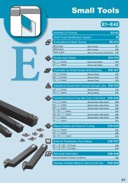


![2012 - MEW - [ENG FRA ITA ESP].indd - Kyocera](https://img.yumpu.com/39423422/1/184x260/2012-mew-eng-fra-ita-espindd-kyocera.jpg?quality=85)