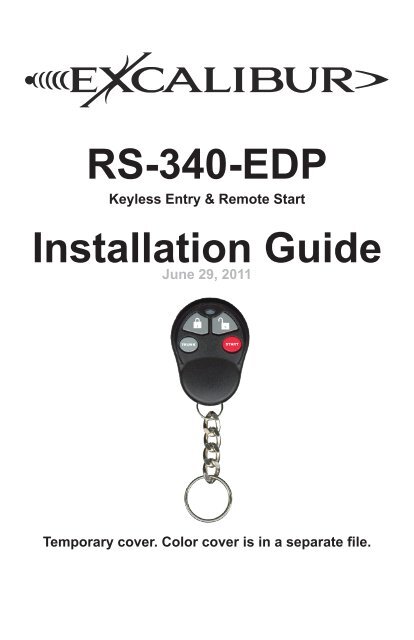
RS-340-EDP Installation Guide - car alarm
RS-340-EDP Installation Guide - car alarm
RS-340-EDP Installation Guide - car alarm

Create successful ePaper yourself
Turn your PDF publications into a flip-book with our unique Google optimized e-Paper software.
Table Of Contents<strong>Installation</strong> Considerations 36 Pin Main Wire Harness 3Red & Red/White Wires - Constant Power (+) Input 3Pink Wire - Ignition #1 (+) Input/Output 3Orange Wire - Accessory (+) Output 4Violet Wire - Start (+) Output 4Pink/White Wire - Ign#2/Programmable (+) Output 412 PIN / 11 Wire Secondary Harness 4Black Wire - System Ground (-) Input 4Brown/Red Wire - Brake Pedal (+) Input 4Black/White Wire - Neutral Safety (-) Input 5Violet/White Wire - Tach Signal Input 5Brown Wire - Horn (-) Output 5White Wire - Flashing Light (+) Output 5White/Black Wire - Flashing Light (-) Output 5Gray Wire - Hood Trigger (-) Input 5Wiring Overview 712 PIN / 11 Wire Secondary Harness (cont’d) 8Lt. Green/Red Wire - OEM Alarm Arm (-) Output 8Lt. Green/Black Wire - OEM Alarm Disarm (-) Output 8Red/White Wire - Trunk Release / CH2 (-) Output 8Green Data Port 83 Pin Satellite Relay Port (RED) 93 Pin Door Lock/Unlock Port (RED) 9Status Light (Optional) 9Valet / Programming Switch 10Window Mount Antenna Module 10Tach Programming 10Programming Transmitters 10Programmable Features 11This device complies with FCC Rules part 15. Operation is subject to the followingtwo conditions, (1) This device may not cause harmful interference and,(2) This device must accept any interference that may be received, includinginterference that may cause undesired operation.The manufacturer is not responsible for any radio or TV interference causedby unauthorized modifications to this equipment. Such modifications could voidthe user’s authority to operate the equipment.2
12 PIN / 11 Wire Secondary Harness (cont’d)Black/White Wire - Neutral Safety (-) InputREQUIRED. This input is a critical safety circuit which allows remote start operationwhenever the gear selector is in park or neutral (automatic transmission), orwhen the parking brake is applied (manual transmission). Remote start will not operateunless this wire sees chassis ground.CONNECTION (Automatic Transmission): Connect this to the neutral safetyswitch wire that shows (-) ground when the gear selector is in the park and neutralpositions.CONNECTION (Manual Transmission): Connect this to the parking brake switchwire that shows (-) ground when the parking brake is applied.Violet/White Wire - Tach Signal InputThis input provides the engine’s RPM signal to the remote start. This is typicallythe most reliable form of engine detection. To use the tach wire, you must changeinstaller feature #3 to the tach wire setting.CONNECTION: This can be connected to any trigger wire for an ignition coil, fuel injector,or the signal to the tachometer in the dash. Use a digital multimeter set for ACvolts to test. The appropriate wire will read between 1-6 volts AC and will increaseas the engine RPM increases.Brown Wire - Horn (-) OutputThis output provides a 1 amp negative output to operate the vehicle’s horn.CONNECTION: Connect this wire to the vehicle’s horn circuit. If the vehicle’s circuitis something other than negative, you will need to use a relay to convert this output.White Wire - Flashing Light (+) OutputThis output provides a 10 amp positive output to flash the vehicle’s parking lights(typically). If the vehicle has a low current negative parking light circuit, use theWHITE/BLACK wire instead.CONNECTION: Connect this wire to the vehicle’s positive parking light circuit. It willshow +12 volts when the parking lights are on. BE SURE NOT TO CONNECT TOTHE DIMMER CIRCUIT WHICH WILL CHANGE VOLTAGE AS YOU TURN THEDIMMER KNOB.White/Black Wire - Flashing Light (-) OutputThis output provides a 250mA negative output to flash the vehicle’s parking lights.If the vehicle has a positive parking light circuit, use the WHITE wire instead.CONNECTION: Connect this wire to the vehicle’s negative parking light circuit. Itwill show ground when the parking lights are on. BE SURE NOT TO CONNECT TOTHE DIMMER CIRCUITWHICH WILL CHANGE RESISTANCE TO GROUND ASYOU TURN THE DIMMER KNOB.Gray Wire - Hood Trigger (-) InputREQUIRED. This is a critical safety circuit that prevents remote start functionswhile the hood is opened. It also monitors the doors in manual transmission mode.CONNECTION: Connect this wire to the OEM hood switch or light. It will showground when the hood is opened. You can also use the included pin switch.(continued on page 8)5
Wiring OverviewWindow-mountReceiver ModuleValetSwitch#1 ScrewMounting DiscAdhesivePad3 PIN DOOR LOCK PORTLock (-) Output - GREENConstant 12v (+) Output - REDUnlock #1 (-) Output - BLUEWIRE LEGENDHard wire connection requiredSupported via DATA port612 PIN HARNESSFlashing Light (-) Output - WHITE/BLACKOEM Alarm Arm (-) Output - GREEN/REDTrunk Release/CH2 (-) Output - RED/WHITESystem Ground (-) Input - BLACKOEM Alarm Disarm (-) Output - GREEN/BLACKHorn (-) Output - BROWNHood Trigger (-) Input - GRAYBrake (+) Input - BROWN/REDTach Input - VIOLET/WHITEFlashing Light (+) Output - WHITENeutral Safety (-) Input - BLACK/WHITE10 AMP
Antenna PortStatus Light Port3 PIN SAT. RELAY PORT (RED)Start (-) Programmable Output - GREENConstant 12v (+) Output - REDStatus (-) Programmable Output - BLUEGreenDataPort30 AMP30 AMP6 PIN POWER HARNESSAccessory (+) Output - ORANGEIgnition #1 (+) Input/Output - PINKStart (+) Output - VIOLETConstant 12v (+) Input - REDIgnition #2 (+) Output - PINK/WHITEConstant 12v (+) Input - RED/WHITE7
12 PIN / 11 Wire Secondary Harness (cont’d)MANUAL TRANSMISSION CONNECTION: The Gray wire also serves as a doorpin input (must see all doors) which is required to perform the “manual transmissionsetup procedure” (detailed in the operation guide). Diode isolate the hood input fromthe door input using two 1 or 2 amp diodes facing the cathodes (stripes) towards thevehicle wires. If the vehicle’s door pin wire is positive, you must invert the signal witha relay.Lt. Green/Red Wire - OEM Alarm Arm (-) OutputThis output provides a 250mA negative pulse when remote start is turned off andwhen the system’s <strong>alarm</strong> is armed.CONNECTION: Connect this wire to the vehicle’s OEM <strong>alarm</strong> arm circuit. Typically,it will show ground when the door cylinder key is turned to the lock position.Lt. Green/Black Wire - OEM Alarm Disarm (-) OutputThis output provides a 250mA negative pulse when remote start is activated andwhen the system’s <strong>alarm</strong> is disarmed.CONNECTION: Connect this wire to the vehicle’s OEM <strong>alarm</strong> disarm circuit. Typically,it will show ground when the door cylinder key is turned to the unlock position.Red/White Wire - Trunk Release / CH2 (-) OutputThis output provides a 250mA negative output when the trunk release/CH2 functionis activated by the controller. The output will remain as long as the controllerbutton(s) is held.CONNECTION: Connect this wire to the vehicle’s existing trunk release switch if itis a low current negative circuit. If the circuit is a high current ground or a positivecircuit, the use of a relay is required.Green Data PortThis port provides a direct digital interface for any Omega IntelliKit or OmegaLinkinterface modules. It can eliminate the need for several wire-to-wire connections.Refer to the wire diagram overview on page 6 to see which circuits are supportedby this port and compare them to the data functions available from the interfacemodule. This port supports our standard D2D (Trilogix) protocol AND the ADS(iDataLink) protocol. This port also supports Omega CarLink system to allow systemcontrol from smartphones.8
3 Pin Satellite Relay Port (RED)Green Wire - Start (-) Programmable OutputThis output provides a 250mA negative pulse when the large VIOLET start wire isactive. It can also be programmed for PULSE AFTER START, STATUS, or DOME-LIGHT SUPERVISION. See installer programmable feature #5.CONNECTION: If a negative start output is needed, connect this directly to the vehicle’snegative starter circuit. Otherwise, use a relay (or <strong>RS</strong>-RP module) to convertthis to a high current circuit.Red Wire - Constant (+) OutputThis output provides a 500mA positive output to drive the positive pin of addedrelay coils.Blue Wire - Status (-) Programmable OutputThis provides a 250mA negative output slightly before and during the large PINKignition wire’s operation. It can also be programmed for IGNITION operation. Seeinstaller feature #6.CONNECTION: This is typically used to activate immobilizer bypass modules. Connectit directly to the module’s activation input.3 Pin Door Lock/Unlock Port (RED)Green Wire - Lock (-) OutputThis provides a 0.8 second 250mA negative pulse for any locking operations. Thepulse timing is programmable by installer feature #8.CONNECTION: Connect this directly to the vehicle’s lock circuit if a negative pulseis required. Otherwise, a doorlock interface and/or relays are required to convert theoutput.Red Wire - Constant (+) OutputThis output provides a 500mA positive output to drive the positive pin of addedrelay coils.Blue Wire - Unlock (-) OutputThis provides a 0.8 second 250mA negative pulse for any unlocking operations.The pulse timing is programmable by installer feature #8.CONNECTION: Connect this directly to the vehicle’s “all door” unlock circuit if anegative pulse is required. Otherwise, a doorlock interface and/or relays are requiredto convert the output.Status Light (Optional)This system includes a status light port that can be utilized with an optional AU-LED-SP or AU-LED-BLU if desired. It is best for the light to be visible from as manyangles around the vehicle as possible for maximum visual theft deterrence. Both ofthe models listed above require a 9/32” hole for custom dash mounting.9
Valet / Programming SwitchThis system includes a valet switch that is typically mounted somewhere in thedriver’s dash area. It is ideal to mount where it can easily be accessed for programming.It has a high quality double stick pad attached that can be used. For texturedor curved dash surfaces, use the included mounting disc & screw. Screw this to thedash then stick the valet switch to the disc.Window Mount Antenna ModuleThis system is equipped with an outboard receiver module. It is designed to bewindow mounted high on the windshield for optimal performance and range. It isbest to mount this module using the double sided stick pad included (be sure toclean glass before adhering). Mount it high in the windshield trying to avoid metalparts of the vehicle as they can create “blind spots” for the antenna. Also, metalbased window tint can have an adverse affect on performance. Route the harness tothe antenna module being sure to avoid sharp metal objects that could compromisethe harness jacket. THE ANTENNA PORT ALSO SUPPORTS ECHO 2-WAY UP-GRADE KITS (Excluding ECHO-COLOR / Hyper Range kits).Tach ProgrammingWhen utilizing the tach wire circuit for engine detection, the vehicle’s tach signalmust be programmed to the remote start for proper operation. After making the tachwire connection, perform the following steps:Step 1: Turn the ignition key “ON”Step 2: Within 5 seconds, press the brake pedal 5 times.(the siren will chirp 5 times)Step 3: Start the engine. The status lights will turn on to indicate it has learned thecurrent tach signal. If it does not light, check your tach connection andstart this procedure again.Step 4: If the engine has a high idle at startup, it may be necessary to allow theidle to “settle” to around 700 RPM. If needed, you can press the valetswitch 1 time to resample the tach signal. The status light will flash off thenback on once the signal has been resampled.Step 5: Turn the ignition key “OFF”.Programming TransmittersStep 1 Have all transmitters which are to operate the system at hand. Then, turnthe ignition “on”.Step 2 Within 5 seconds of turning on the ignition, press the Valet Switch 5 times.The horn will briefly sound, confirming that for the next 10 seconds the system isready to learn a transmitter/controller code.Step 3 Press the “lock” button on each transmitter one at a time. The system willchirp the horn once to confirm that each was learned. The transmitter’s other threebutton’s are automatically assigned at this point. If a code is not received within a10 second period, the learning process will end, as indicated by another horn honk.Step 4 Turn the vehicle’s ignition “off”.10
Programmable FeaturesA matrix of all programmable features and their options are below. For detailed informationon each feature, please refer to the operation manual. Use the procedurebelow to make any necessary changes.Step 1 Turn the ignition key “ON”, then “OFF”Step 2 Within 5 seconds of step 1, press the valet switch 5 times to access userfeatures (Press 10 times to access installer features). ~ The horn will honk and thestatus light will turn on.Step 3 Within 10 seconds of step 2, press the valet switch the number of times correspondingwith the desired feature’s number. ~ The horn will honk and the parkinglights will flash equal to the selected feature.Step 4 Change the feature by pressing the transmitter button that corresponds withthe desired setting. ~ The horn will honk and the parking lights will flash equal to theselected setting.Step 5 If you wish to change more features, repeat steps 3 & 4 at this time.Step 6 To exit programming, turn the ignition key “ON” then “OFF”. Or, you can wait10 seconds for programming mode to expire.User Feature Programming: Ignition on, off, press valet 5 times# Feature Lock Button Unlock button Trunk button ”START” button1 Engine Run Time 10 min 5 min 15 min 20 min2 Steady/Flashing lights for <strong>RS</strong> Steady Flashing3 Horn Honk Volume Low Hi On Demand OFF4 Pulse Horn/Steady Siren Pulsed Lo Pulsed Med Pulse Hi Steady Siren5 Doors Lock w/ Ign. ON ON OFF6 Doors Unlock w/ Ign. OFF ON OFF7 Unlock w/ Trunk Release ON OFFInstaller Feature Programming: Ignition on, off, press valet 10 times1 <strong>RS</strong> Activation 1 press 2 presses 3 presses 4 presses2 PINK/WHITE wire function Ignition Accessory Start3 Engine Detection4 Gas or Diesel Engine GasTachless Hi Tachless Lo Tach Wire DatatachCrank Only (Press Lock +Unlock)Diesel(15 sec delay)Diesel(20 sec delay)Diesel(30 sec delay)5 Sat. Port Green Wire Starter Pulse After Start Status Domelight6 Sat. Port Blue Wire Status Ignition7 Crank Time 0.7 Sec 1.00 Sec 1.5 Sec 2.25 Sec8 Doorlock Outputs 0.8 Sec 3 sec Double Unlock Total Closure9 Remote Start Lock Control Off Lock After StartUnlock BeforeStartBoth10 Turbo Timer OFF 1 min 2 min 3 min11 Manual Transmission <strong>RS</strong> ON OFF12 Data Port Protocol D2D (Trilogix) ADS (iData)11
Back CoverColor cover is in aseparate file.