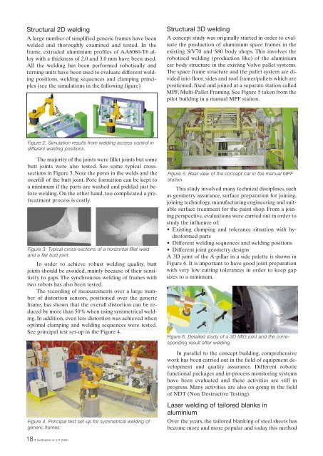
Structural 2D weldingA large number of simplified generic frames have beenwelded and thoroughly examined and tested. In theframe, extruded aluminium profiles of AA6060-T6 alloywith a thickness of <strong>2.</strong>0 and 3.0 mm have been used.All the welding has been performed robotically andturning units have been used to evaluate different weldingpositions, welding sequences and clamping principles(see the simulations in the following figure)Structural 3D weldingA concept study was originally started in order to evaluatethe production of aluminium space frames in theexisting S/V70 and S80 body shops. This involves therobotised welding (production like) of the aluminiumcar body structure in the existing Volvo pallet systems.The space frame structure and the pallet system are dividedinto floor, sides and roof frames/pallets which arepositioned, fixed and joined at a separate station calledMPF, Multi-Pallet Framing. See Figure 5 taken from thepilot building in a manual MPF station.Figure <strong>2.</strong> Simulation results from welding access control indifferent welding positions.The majority of the joints were fillet joints but somebutt joints were also tested. See some typical crosssectionsin Figure 3. Note the pores in the welds and theoverfill of the butt joint. Pore formation can be kept toa minimum if the parts are washed and pickled just beforewelding. On the other hand, too complicated a pretreatmentprocess is costly.Figure 3. Typical cross-sections of a horizontal fillet weldand a flat butt joint.In order to achieve robust welding quality, buttjoints should be avoided, mainly because of their sensitivityto gaps. The synchronous welding of frames withtwo robots has also been tested.The recording of measurements over a large numberof distortion sensors, positioned over the genericframe, has shown that the overall distortion can be reducedby more than 50% when using symmetrical welding.In addition, even less distortion was achieved whenoptimal clamping and welding sequences were tested.See principal test set-up in the Figure 4.Figure 5. Rear view of the concept car in the manual MPFstation.This study involved many technical disciplines, suchas geometry assurance, surface preparation for joining,joining technology, manufacturing engineering and suitablesurface treatment for the paint shop. From a joiningperspective, evaluations were carried out in order tostudy the influence of:• Existing clamping and tolerance situation with hydroformedparts• Different welding sequences and welding positions• Different joint geometry designsA 3D joint of the A-pillar in a side palette is shown inFigure 6. It is important to have good joint preparationwith very low cutting tolerances in order to keep gapsizes to a minimum.Figure 6. Detailed study of a 3D MIG joint and the correspondingresult after welding.In parallel to the concept building, comprehensivework has been carried out in the field of equipment developmentand quality assurance. Different roboticfunctional packages and in-process monitoring systemshave been evaluated and these activities are still inprogress. Many activities are also on-going in the fieldof NDT (Non Destructive Testing).Figure 4. Principal test set-up for symmetrical welding ofgeneric frames.Laser welding of tailored blanks inaluminiumOver the years, the tailored blanking of steel sheets hasbecome more and more popular and today this method18 • <strong>Svetsaren</strong> <strong>nr</strong> 2 • <strong>2000</strong>
is widely used within the automotive industry all overthe world. In the case of certain applications, the benefitsof reduced material weight and total costs outweighthe increased cost of the joining process and the formingtools, which justifies this investment. The next stepis to use the knowledge acquired from tailored blankingin steel and adapt it to aluminium.Relatively simple welding equipment can be usedfor tailored blanking operations as welding is performedin two-dimensional form. In most cases, thewelding is done with a gantry system for handling themirror in combination with a high-power CO 2 laser of5-8 kW, but, in the case of aluminium tailored blanking,Nd:YAG laser welding is an alternative due to the higherabsorption of the Nd:YAG laser light. Less powercan then be used to reach the same weld speeds and lessheat is put into the material. Experience has shown thatboth Nd:YAG- and CO 2 lasers can be used for aluminiumtailored blanking [1].Figure 7. 4 kW laser source and set-up with linear fixture forclamping.When welding aluminium, a power density of atleast 1 MW/cm 2 on the workpiece is required, otherwisethe laser beam will reflect on the surface of thematerial. For a stable welding process, and to performkeyhole welding, at least 2 MW/cm 2 is required, due tothe high reflection and heat transfer of aluminium. Previously,aluminium has only been weldable when usingfocal lengths of about 100 mm, projecting a very smallspot on the material to maintain the required powerdensity. The increased beam quality and output powerof today's Nd:YAG lasers make it possible to weld aluminiumwith up to twice the focal length, 200 mm. Advantagesinclude the reduced contamination of the sensitivelenses on the welding equipment, reduced sensitivityto fluctuation in height, allowing cheaper guidancesystems, and increased access. A comparisonbetween weld speeds for different focal lengths can beseen in Figure 8.Too short a focal length results in a great deal ofspatter and an oxidised root side. Defocusing the focalpoint does not stabilise the welding process. Due to theaggressive welding process and the short distance, theprotection glass of the optics contaminates quicklyAs different from steel, aluminium normally displaysa decrease in strength after welding. Previous investigationshave shown that the tensile strength of5000-series (Al-Mg) aluminium alloys can also be obtainedin the weld, but at a reduced elongation [3]. Forheat-treatable alloys, like the 6000-series (Al-Mg-Si),the weld zone normally shows a decrease in tensilestrength to 70-90% or less than that of the base material[4].The condition of the material prior to welding hasalso been shown to be critical for the strength obtainedafter welding [5]. Material in the soft condition, normally5000-series, does not display any difference in Rp andRm before and after welding, while 6000-material in thetempered condition T4 shows a decrease in Rm to 65-85% of the base material, while Rp is unaffected, andmaterial in T6 condition shows a decrease to 65-85% inboth Rm and Rp.In the case of tailored blanking, material from boththe 5000- and 6000-series alloys is of interest, dependingon the final application. The differences betweenthe two alloy types are the content of the alloying elementsmagnesium and silicon. For the materials normallyused within the automotive industry, the magnesiumcontent of the Al-Mg alloys is generally in therange of 1.8-3.0%, while in the Al-Mg-Si alloys the contentof the elements is 0.4-0.6% for magnesium and 0.9-1.2% for silicon. The mixture of magnesium and siliconin 6000-series alloys has been shown to be sensitive tocracks in the weld zone.The laser welding of tailored blanks is normallyperformed in a butt weld configuration with sheets ofdifferent thickness or material quality. The welding orientationof the materials used in the blank can vary.Welding is either performed on the flush surface,orienting the step of the different thickness downwards,or on the step side. Choosing one or the other influencesthe weld quality and the achieved weld speed [2].2 1 2 1Weld Speed [m/min]12108642150 mm200 mm00,5 1,0 1,5 2,0 2,5 3,0 3,5Figure 8. Weld speed as a function of focal length andmaterial thickness. Material AA-5052, welded from stepside [2].Figure 9. Welding position step side versus flush side.Depending on the thickness combination, the differencein weld speed between the flush side and thestep side increases as the difference in thickness increases,see the following figure. On the other hand, thetop and root bead appearances are much smootherwhen welding on the step side, see the following figure.<strong>Svetsaren</strong> <strong>nr</strong> 2 • <strong>2000</strong> • 19