Svetsaren nr 2. 2000 - Esab
Svetsaren nr 2. 2000 - Esab
Svetsaren nr 2. 2000 - Esab
- No tags were found...

You also want an ePaper? Increase the reach of your titles
YUMPU automatically turns print PDFs into web optimized ePapers that Google loves.
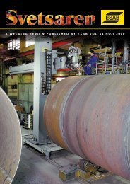
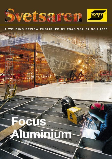
A WELDING REVIEW PUBLISHED BY ESAB VOL. 54 NO.2 <strong>2000</strong>FocusAluminium
A welding review published by ESAB AB, Sweden No. 2 <strong>2000</strong>Articles in <strong>Svetsaren</strong> may be reproduced without permission but withan acknowledgement to ESAB.PublisherBertil PekkariEditorLennart LundbergEditorial committeeKlas Weman, Lars-Göran Eriksson, Johnny Sundin, Johan Elvander, Sten Wallin,Bob Bitsky, Stan Ferree, Ben Altemühl, Manfred Funccius, Susan FioreAddressESAB AB, Box 8004, SE-402 77 Göteborg, SwedenInternet addresshttp://www.esab.comE-mail: info@esab.sePrinted in Sweden by Skandia-Tryckeriet, GöteborgThe fabrication of the Pacificat 1000series high speed ferry at VancouverShipyards in Canada.Contents Vol. 54 No. 2 <strong>2000</strong>3The advancement of aluminium within thewelding fabrication industry and its manyproduct design applicationsApplications of aluminium and the reasonsfor the advancements of aluminium withinthe welding fabrication industry.25Stubends & SpatterShort news.6Friction Stir welding of AA 5083 andAA 6082 aluminiumA report on microstructural observations ofjoints welded using Friction Stir Welding.28ESAB’s partnership with Canada’s westcoast shipbuilding industry—Pacificat 1000 series high speed ferryA project which has allowed ESAB andVancouver Shipyards to make great stridesfor a future in aluminium welding.11Equipment for aluminium weldingProcesses and equipment in aluminiumwelding.31A century of aluminium — a product forthe futureThe first aluminium items appeared on themarket around 1890 and today aluminium isthe second most frequently used metal aftersteel.14Adding NO to the Argon or Argon/Heliummixture does the trickAdding NO remarkably stabilises the arcand results in a more regular surface of theweld.34Tube bending and hydroformingThe hydroforming of aluminium extrusionsis regarded as the only method in manycases when producing structural automotivecomponents.17High quality aluminium welding—a keyfactor in future car body productionCar body design and manufacturing engineerscontribute to new ways to reduce fuelconsumption.36Troubleshooting in aluminium weldingSome of the most common problems thatare encountered when changing to aluminiumwelding.2 • <strong>Svetsaren</strong> <strong>nr</strong> 2 • <strong>2000</strong>
The advancement of aluminiumwithin the welding fabricationindustry and its many productdesign applicationsby Tony Anderson, Technical Services Manager, AlcoTec Wire Corporation, USAThis article will consider the many applications of aluminium withinthe welding fabrication industry, the reasons for the advancement ofaluminium within these industries and the involvement of AlcoTec WireCorporation in assisting industry to move forward with improvedaluminium welding technology.Figure 1. ThePlymouth Prowlermoving towardsthe aluminiumintensivevehicle.Aluminium is the second most plentiful metallic elementon earth and became an economic competitor inengineering applications as recently as the end of the19th century. The appearance of three important industrialdevelopments resulted in a demand for a materialwith characteristics consistent with those of aluminiumand its alloys and this greatly benefited growth withinthe production of this new material. When the electrolyticreduction of alumina (Al2O3) dissolved in moltencryolite was independently developed by Charles Hallin Ohio and Paul Heroult in France in 1886, the firstinternal combustion engine-powered vehicles were appearing.One hundred years later, aluminium was toplay a major role as an automotive material of increasingengineering value. Electrification would developrapidly and require immense quantities of lightweightconductive material for the long-distance transmissionof electricity. The Wright brothers gave birth to an entirelynew aircraft industry which grew in partnershipwith the aluminium industry.The first commercial applications of aluminiumwere novelty items such as mirror frames and servingtrays. Cooking utensils were also a major product marketedat an early stage. In time, aluminium grew in itsdiversity of applications to such an extent that virtuallyevery aspect of modern life was directly or indirectly affectedby its use.Today, the unique characteristics of aluminium,light weight, high strength, high toughness, extremetemperature capability, versatility of extruding, excellentcorrosion resistance and recycling capabilities,make it the obvious choice of material for engineersand designers for a variety of welding fabrication applications.<strong>Svetsaren</strong> <strong>nr</strong> 2 • <strong>2000</strong> • 3
Automotive industryPerhaps the most dynamic advancement in aluminiumwelding fabrication within the USA today is takingplace within the automotive industry. Promoted primarilythrough environmental issues such as increased fuelefficiency, corrosion resistance and recycling, more andmore components made of aluminium are appearing inthe average automobile. The recent development ofmajor structural components fabricated entirely fromaluminium, such as engine cradles, front and rear suspensionframes, driveshafts and wheels, is complementingthe more traditional non-structural componentssuch as heat exchangers,radiators and airconditioning units.Most of these weldedstructural componentsare manufacturedusing 6xxx seriesbase alloys, makinguse of the abilityof this material toproduce complex extrudedshapes andwelded with theGMAW (MIG) weldingprocess. Anotherissue other than fuelefficiency which is associatedwith the useof aluminium withinthis industry is safety. The basic physical characteristicsof aluminium lend themselves to creating automobilesthat not only perform better in a collision but can actuallyhelp to prevent crashes altogether. The strength-toweightratio of aluminium allows engineers to constructlarger vehicle crumple zones for improved energy absorption.Aluminium structures can be designed to absorbthe same energy as steel at only 55% of the weight.This weight-saving results in less kinetic energy needingto be absorbed in a collision. Aluminium-intensive vehiclesprovide better handling and braking capability,thereby improving their crash-avoidance ability. Avehicle made of conventional material weighing 3,300lbs and travelling at 60 mph requires 213 feet to stop.Given the same drivetrain, an aluminium-intensive vehicleof the same size would weigh 2,000 lbs and couldstop in 135 feet. Similar improvements are being seen inacceleration abilities, when a little extra speed couldmake the difference in avoiding a collision. Weldingprocedures used within this industry vary, but will typically,wherever possible, make use of robotics. The fabricationof thin-wall heat exchangers involves the use ofthe 4047 filler alloy which contains 11.0 to 13.0% siliconand provides exceptional fluidity which helps to reduceleakage rates and improve productivity.The thicker materialstructural applications within this industry are oftenable to make use of filler alloy 5356 for its improvedstrength and impact properties.Figure <strong>2.</strong> Welding fabricated aluminium wheels.ShipbuildingThe fast ferry projects have advanced the use of aluminiumin shipbuilding through the development of a newconcept in marine transportation. With an eye on profits,shipping companies are looking at high-speed aluminiumferries as a means of fast, efficient, lowmaintenancetransport.The term “fast ferries“ applies tohydrofoils, wave-piercing catamarans and both monohulledand multi-hulled vessels built to carry large payloadsof passengers and cargo at high speeds. Typically,these vessels are around 100-130 feet in length and travelat 30-35 knots (35-40 mph). Aluminium-intensivemega-ferries aremassive vesselsmeasuring approximately260 feet inlength and carryingup to 700 passengersand 150 cars. Quadrimaransare amongthe newest marinetransportation innovations.Measuring180 feet in length,newer versions aredesigned to carry600 passengers.These fast ferriesregularly travelat 60 knots (69mph), but theycould achieve speeds of up to 110 knots (126.5 mph).The shipbuilding industry has made use of the highstrengthmagnesium base alloys such as 5083 weldedwith 5183 filler alloy in order to obtain the minimumtensile strength requirements as specified in the codes.Often argon/helium shielding gas mixes are used to reduceporosity and obtain broader and deeper penetrationfor these high-quality welds. The unique combinationof light weight, high strength and corrosion resistancecharacteristics offered by aluminium makes thesehigh-speed developing marine applications possible.Recreation and sporting equipmentThe advancement of high-tech sporting equipment andthe increased use of high-strength heat-treatable aluminiumalloys such as the 7xxx series has revolutionizedthis industry. Many of the latest designs have incorporatedthese lightweight, high-performance aluminiummaterials. Bicycle frames, baseball bats, golfclubs, sleds and snowmobiles are some of the manyproducts within this industry which are currently dependenton aluminium alloys.This industry, with its thinwall joining and its complex heat treatment, has promotedthe development and use of specialized filler alloysdesigned to respond to thermal treatment and thedevelopment of welding techniques and equipmentproduced to comply with their strength and cosmeticapplication.4 • <strong>Svetsaren</strong> <strong>nr</strong> 2 • <strong>2000</strong>
Transportation and containersFor reasons similar to those in the automotive industry,transportation vehicles are including more aluminium.Heated rail cars with line heaters and steam lines makeuse of aluminium base alloy 5454, welded with filler alloy5554 for their strength and high temperature characteristics.Cryogenic tanks are manufactured frombase alloy 5083, welded with filler alloy 5183 for theirhigh strength at low temperature characteristics. Truckbodies and panels are manufactured from 5052, 5086,5083 and 6061 and are often welded with filler alloy5356 for its strength characteristics.Defence and aerospaceThese industries use high-strength 5xxx series(Al-Mg) non-heat-treatable base alloys for some applications,but they also make use of some of the more specializedheat-treatable aluminium alloys with superiormechanical properties. Aluminium armour plating isused for its impact strength and strength-to-weight ratio.Alloy 5083 and 7039 base materials are welded with 5356filler, while 2519 base is welded with 2319 filler material.Missiles are constructed of 2019, welded with 4145 and2219 welded with 2319 filler. Perhaps the most exotic aluminiumalloys, with exceptional strength over a widerange of operating temperatures, are used in the aerospaceindustry. These alloys include 2219, 2014, 2090,2024 and 7075. These base materials are typically used inspecialized high-performance applications and havetheir own welding characteristics and associated problemswhich require special consideration when joining.AlcoTec Wire Corporation’s involvement inthe advancement of aluminium weldingtechnologyAlcoTec has continually worked with industry to provideproducts and services to meet its specific needs.AlcoTec has developed aluminium weld wire manufacturingmethods which produce products that exceed thestandard manufacturing specifications. Some of theseproduct characteristics are incorporated in the standardproduct, such as a diameter control of one-tenth the nationalstandard requirement. Others are applied to customizedproducts for specialized applications, such asproprietary chemistries to assist with desired weld characteristics.These advancements have been developedthrough working closely with industry in order to provideproducts which will meet our customers’ requirements.AlcoTec has provided technical training for industrythrough its School for Aluminium Welding Technology.Hundreds of students, consisting of welding engineers,welding inspectors, welding supervisors andwelding operators, have attended specialized training inorder to upgrade their personal skills and assist theirorganization to advance within the aluminium weldingfabrication industry.AlcoTec has applied its aluminium engineering experienceto many new projects throughout the aluminiumwelding fabrication industry by providing assistancewith the development of welding procedures, thewelding and testing of new materials, evaluations ofwelding equipment for aluminium, investigations ofwelding problems and failure analyses of welded components.AlcoTec has worked for many years to developtechnical literature, welding guidelines and training materialand has been constantly involved, through itsmembership of society technical committees, in the developmentof national codes and standards relating tothe manufacture of aluminium welding wire and the designand fabrication of welded aluminium structures.AlcoTec has developed a unique reputation forproviding a premium quality product complemented bythe highest level of technical support. This combinationhas been designed to ensure that our customers receivethe ultimate value-added package which provides themwith the capability to produce the highest quality weldedcomponents at the lowest overall cost.The use of aluminium continues to grow within thewelding fabrication industry in terms of both size andcomplexity and with it the need for aluminium filler alloyswhich will meet these needs, the advancement ofwelding equipment specifically designed for welding aluminiumand the need for resources which can provideindustry with technical support.Figure 3. Aluminium used in high speed marine applications.About the authorTony Anderson is Technical Services Manager of Alco-Tec Wire Corporation USA, Chairman of the AmericanAluminum Association Technical Committee for Welding,and member of the American Welding Society(AWS) Committee for D1.2 Structural Welding Code –Aluminum<strong>Svetsaren</strong> <strong>nr</strong> 2 • <strong>2000</strong> • 5
Friction Stir welding of AA 5083and AA 6082 aluminiumby Helena Larsson and Leif Karlsson, ESAB AB, Göteborg and Lars-Erik Svensson,Volvo Teknisk Utveckling ABNowadays, aluminium alloys are used in many applications inwhich the combination of high strength and low weight is attractive.Shipbuilding is one area in which the low weight can be ofsignificant value. In fact, the first aluminium boat was built in 1891and the first welded aluminium ship in 1953 [1].The two most frequently-used aluminium alloys for shipbuildingare AA 5083 (AlMg4.5Mn) for plates and AA6082 (AlSi1Mg) for extrusions. The main alloying elementin the 5000 series is magnesium.A magnesium contentof around 5% provides good strength and high corrosio<strong>nr</strong>esistance in sea water. The 6000 series is mainlyalloyed with magnesium and silicon, which results in ahardenable alloy. Al is also of interest in many other applications,such as the topside structures of offshore platforms,railway wagons and in the brewing industry.MIG welding is a flexible and productive methodand is therefore widely used for welding aluminium alloysin shipbuilding. However, two disadvantages withMIG welding are the deformation of the base materialand a decrease in the strength of the heat affected zone.Other fusion welding techniques like TIG and plasmawelding are also widely used. However, these methodshave the same weakness as MIG welding. An alternativeto other fusion welding methods is the recently introducedFriction Stir Welding technique (FSW)The components that are going to be joined areplaced on a backing plate and clamped using a powerfulfixture. A rotating tool, consisting of a specially profiledpin with a shoulder, is forced down into the materialuntil the shoulder meets the surface of the material(see Fig 1). The material is thereby frictionally heatedto temperatures at which it is easily plasticised. As thetool is moved forwards, material is forced to flow fromthe leading face of the pin to the trailing one.The technique was developed at TWI at the beginningof the 1990s [1] and processing technologies havebeen further developed by ESAB AB [2]. The first installationhas been used successfully for more than oneyear for joining long plates and panels, up to 6m by16m, mainly in AA 5083 and AA 6082 aluminium [2].Although the practical application of the FSW techniquehas been successful, there is still a lack of designdata and understanding of the failure mechanisms.Furthermore, as has been pointed out in a recentsummary, much of the microstructural knowledge offriction stir welds is at an embryonic stage [3].The aim of the present paper is to report on microstructuralobservations and provide informationabout the mechanical properties of joints welded usingFSW.<strong>2.</strong> Experimental set-up<strong>2.</strong>1 Welding and materialsFriction stir welds were produced in AA 5083 and AA6082 aluminium using different combinations of platethickness and welding speed, as shown in Table 1.Alloy AA 5083 is a non-heat-treatable Al-Mg alloy(4.6%Mg, 0.6%Mn, 0.3%Si) with good corrosion resistance,which is commonly used in seawater applications.AA 6082 aluminium is alloyed with Mg and Si(0.7%Mg, 0.5%Mn, 0.9%Si) and age hardens by theformation of Mg2Si precipitates.Alloy AA 5083 AA 6082Plate thickness (mm) 15 10 10 6 6 10 10 5 5Welding speed (cm/min) 4.6 6.6 9.2 9.2 13.2 26.4 37.4 53 75Table 1. Plate thickness and welding speed for friction stir welds.6 • <strong>Svetsaren</strong> <strong>nr</strong> 2 • <strong>2000</strong>
atio R (=min stress/max stress) was 0.1 and the stressrange was 90 to 150 Mpa. The fatigue samples were inthe as-welded condition without machining the weldtop and root faces.Figure 1. Macrographs showing the appearance of a frictionstir weld in 6 mm AA 5083, welded at 13.2 cm/min. Thenugget zone ring pattern can be clearly seen in all threeperpendicular sections.a) Cross-sectionb) Section parallel to the top surface just below the centreof the nugget regionc) Longitudinal section to the left (in Fig. 1a) of the originaljoint face.Figure <strong>2.</strong> Sections of a friction stir weld in 5 mm AA 6082,welded at 75 cm/min. The macrographs show the nuggetzone ring pattern in three perpendicular sections.a) Cross-sectionb) Section parallel to the top surface just below the centreof the nugget regionc) Longitudinal section to the left (in Fig. 2a) of the originaljoint face.<strong>2.</strong>2 Microstructural studiesAn in-depth microstructural investigation was carriedout on the 5 mm AA 6082, welded at 75 cm/min, and onthe 6 mm AA 5083, welded at 13.2 cm/min. Overviewsof the microstructure were obtained using light opticalmicroscopy (LOM), whereas scanning electron microscopy(SEM) was used for the more detailed studies.<strong>2.</strong>3 Hardness measurements andmechanical testingA detailed hardness assessment was made of the twowelds subjected to an in-depth microstructural study.The hardness (HV1) was measured horizontally andvertically through the centre of the nugget, on crosssections.Transverse tensile testing of the welds was also performedand the location of the fracture relative to theweld centre was examined. Detailed microhardnessmeasurements (HV25g) were made to clarify whetherthere were any hardness differences between the ringpattern and locations between rings. The accuracy wasestimated at two to three units for HV1 and four to sixunits for HV25g.Fatigue tests were conducted at room temperatureand with a constant amplitude in tensile testing, accordingto ASTM E466.The frequency was 140 Hz.The load3 Results3.1 Macrostructure of the weld zoneThe structure of FSW welds contains features that arenot found in fusion welds. In a cross-section of a weldedjoint, the central part has a shape of a “nugget” (oftenasymmetrical), in contrast to the well-defined beadsof a MIG weld. Larsson et al. [4] compared FSW weldswith MIG welds and noted the presence of the “annualrings” (or onion ring structure, as defined by Threadgill[2]) in the FSW weld area which typically consists ofconcentric ovals.Immediately adjacent to the nugget is the plastically-deformedand heat-affected so-called “thermomechanically-affectedzone” [2], which has only beenaffected by the heat flow.Macrographs in Figures 1 and 2 show one weld inAA 5083 and one in AA 6082 respectively, in three perpendicularsections. The cross-sections (Figs. 1a and 2a)show that the overall shape of the nugget is very variable,depending on the alloy used and the precise processconditions. However, one common feature is thecentral “ring structure” and the more well-defined nuggetboundary on the side (to the right in Figs. 1a and 2a)where the tool travel and rotation direction coincide.Appendages to the nugget, extending to the edge of thetool shoulder on the upper surface, can also be seen onthis side of the nugget. The complex shape of the nuggetand the “ring structure” is also evident in sectionsparallel to the top surface (Figs. 1b and 2b) and in longitudinalsections parallel to the original joint face(Figs. 1c and 2c). However, it should be borne in mindthat the appearance of the “ring structure“ in these sectionsis dependent on the precise location of the section.3.2 Microstructure of base material and weld zoneThe microstructure of the 6 mm AA 5083 material washomogeneous with grains elongated in the rolling direc-Figure 3. SEM backscattered electron images of weld zoneand base material in AA 608<strong>2.</strong>a) Base materialb) Equiaxed grains in the nugget regionc) Transition between the thermomechanically-affectedzone (right) and the nugget zone. Note the similar grainsize of the “border ring” and the interior of the nugget.<strong>Svetsaren</strong> <strong>nr</strong> 2 • <strong>2000</strong> • 7
Figure 4 (left) Horizontal hardness profile across friction stir weld in AA 608<strong>2.</strong>Figure 5 (right) Horizontal hardness profile across friction stir weld in AA 5083 measured 1.7 mm from the root face.The hardness profile was measured <strong>2.</strong>5 mm from the root face and shows hardness minima in the thermomechanicallyaffectedzone.Alloy AA 5083 AA 6082Plate thickness (mm) 15 10 10 6 6 10 10 5 5Welding speed (cm/min) 4.6 6.6 9.2 9.2 13.2 26.4 37.4 53 75Tensile strength (MPa) 318 344 331 312 303 226 236 254 254Table <strong>2.</strong> Transverse tensile properties of friction stir welds.tion. Typical grain sizes were 30 m along the rolling directionand 20 m across. In AA 6082, the grain size wasnon-homogeneous (Fig. 3a), due to partial recrystallization.Recrystallized grains were about 10 m in size,whereas the size of non-recrystallized grains typicallyvaried between 50 m and 150 m.The recrystallization of the nugget zone during frictionstir welding effectively wiped out any trace of theprevious grain structure. The nugget zone in both materialsconsisted of fine, equiaxed grains with a grain sizeof about 10 m (Fig. 3b).The transition between the nuggetand the thermomechanically-affected zone wasclearly visible in the AA 6082 alloy, as shown in Fig. 3c.This figure also illustrates that the “ring contrast“ is notdue to grain size differences. The contrast instead appearsto be related to variations in grain orientationand possibly to the degree of relative disorientationbetween adjacent grains.3.3 HardnessThe hardness of unaffected base material was approximately75 HV1 and was practically constant across theweld, both horizontally and vertically, in AA 5083(Fig. 4).The horizontal hardness profile across the weld in AA6082 (Fig. 5) had a significantly different appearance. Unaffectedbase material is harder (about 110 HV1) andthere is a decrease in hardness towards the weld, with aminimum of about 60-65 HV1 in the thermomechanicallyaffectedzone.The hardness of the nugget zone itself is typically70-75 HV1. A slight tendency towards decreasinghardness towards the top surface of the weld was noted atthe centre of the weld. The location of isohardness curves,corresponding to 85 HV1, approximately corresponds tothe width of the tool shoulder at the top side and becomesnarrower towards the root side.Microhardness measurements (HV25g) across thenugget zone in AA 6082 did not show any systematicvariations that could be correlated to the ring pattern(see also [5]). Nor did measurements in rings andbetween rings reveal any differences in hardness.3.4 Tensile propertiesThere is a considerable difference in the transversestrength of friction stir welds in the two alloys (Table 2).The transverse strength was between 303 and 344 MPafor AA 5083, while AA 6082 had a transverse strengthin the range of 226 to 254 MPa.An interesting pattern was found when examiningthe location of the fracture. For welds in AA 5083, thefracture in most cases was close to the centre of theweld and the fracture surface was generally inclined8 • <strong>Svetsaren</strong> <strong>nr</strong> 2 • <strong>2000</strong>
Figure 6 (left). Results of fatigue testing of FSW welds in base material AA 5083. All values are well above the design curve.Figure 7 (right). Fatigue properties of FSW weldments in AA 6082 base material. All experimental values are above thedesign curve.about 45 degrees. The fracture surface was close to thecentre of the weld on the root side, but the original jointline never appeared to be the initiation point. In AA6082, the fracture was with few exceptions close towhere the outer edge of the tool shoulder had touchedthe top side. The fracture surface was inclined, with thefracture surface closer to the weld centre at the rootside but still displaced a few mm.3.5 Fatigue propertiesIn Figures 6 and 7, the fatigue properties of FSW weldmentsare presented and compared with design curves[8]. In most samples, the fracture was initiated in thebase material, or in the centre of the weld. In only a fewsamples, the fractures started in the weld metal/basematerial transition region. All the tested samplesshowed very good fatigue behaviour. There are someindications that a lower welding speed results in higherresistance in the weld, although this has to be confirmedby further testing. Welds in base material AA 5083showed better fatigue properties, compared with weldsin AA 608<strong>2.</strong> The scatter was also larger for welds in AA6082 than for welds in AA 5083.4.Discussion4.1 MicrostructureSpecial attention was paid to the annual rings seen in thenugget zone. A similar pattern has previously been observedin aluminium welded using pulsed TIG. This ringpattern is due to varying grain size caused by a periodicchange in cooling rate. However, no difference in grainsize was noted between rings and areas between rings infriction stir welds (Fig.3c). Nor was any difference in particledistribution detected [6]. The absence of hardnessdifferences between rings and areas between rings alsosupports the assumption that the ring structure is not associatedwith precipitation.A likely explanation is thereforethat the movement of the rotating, profiled pin-toolthrough the material results in periodic variations instrain. This produce variations in grain orientation, or inthe relative orientation of adjacent grains, resulting indifferences in etching response. However, further investigationsare needed to verify this hypothesis.4.3 Mechanical propertiesWelded AA 5083 had a tensile strength close to that ofmaterial in annealed condition, whereas the weldstrength of AA 6082 was between that typical of coldagedand heat-treated material. From measuredstrength levels it would therefore be expected that fracturewould occur in the “most annealed region“ in AA5083 welds. This is in good agreement with the fractureusually taking place in the fully-annealed, equiaxed microstructurein the centre of the nugget zone. It was difficultto predict where to expect fracture in AA 6082from strength comparisons. However, there was a clearcorrelation between fracture path and the measuredline of lowest hardness.<strong>Svetsaren</strong> <strong>nr</strong> 2 • <strong>2000</strong> • 9
4.4 Fatigue propertiesThe fatigue resistance of a weld structure is largely controlledby the geometry and quality of the weldments.The fatigue stresses on the structure in a ship comefrom two main sources, externally applied loads fromits progress through the water and initially generatedloads from the machinery. Studies of fatigue resistancehave generated a large amount of data which are summarisedas design curves in the European Recommendationsfor Aluminium Alloy Structures Fatigue Design(ECCS) [8] and British Standard 8118 “Structural Useof Aluminium” [9]. The quality of workmanship cangreatly affect the durability of structures and for manyyears the welding standards have specified quality levelsfor weldments.This investigation shows good fatigue properties forFSW samples with values above the design curves (Figures6 and 7). The absence of any weld reinforcement,which results in minimal stress concentrations, is probablya major factor contributing to the good fatigue resistance.There are some differences between the fatigueproperties of FSW welds in AA 5083 and AA6082 base material. Welds in AA 5083 have a higher fatiguerange, compared with welds in AA 6082 whichshowed a somewhat lower strength and large scatter.[5] J. Karlsson, B. Karlsson, H. Larsson, L. Karlsson, andL.-E. Svensson: Proc. INALCO 98, 7th Int. Conf. OnJoints in Aluminium, Cambridge, UK, 15-17 April1998.[6] L. Karlsson, L.-E. Svensson and H. Larsson: Proc.5th Int. Conf. on trends in welding research, PineMountains, GA, USA, 1-5 June 1998.[7] Å. Andersson, A. Norlin, and J. Backlund: Proc.International Engineering Conference “AdvancedTechnologies & Processes” Stuttgart, Germany, 30Sept-2 Oct 1997.[8] European convention for structural steelwork.European Recommendations for Aluminium AlloyStructures Fatigue Design. ECCS 68, 199<strong>2.</strong>[9] British Standard BS8118, part 1 – Structural Use ofAluminium.5.Conclusions• The microstructure and hardness in rings inside thenugget zone of friction stir welds did not differ fromthat between rings.• Most probably the nugget zone ring pattern is an effectof periodic differences in the crystallographic orientationof grains, or varying relative orientation inadjacent grains.• The hardness only varied a little across the weld inAA 5083, whereas a marked minimum was seen inthe thermomechanically-affected zone in AA 608<strong>2.</strong>• Fracture in tensile specimens coincided with the lineof lowest hardness for AA 6082 and was located inthe nugget zone for AA 5083. The fracture path wasnot related to the ring pattern.6. References[1] W.M. Thomas: Int. Patent Application No PCT/GB92/02203, 10 June 1993.[2] K.-E. Knipström, and B. Pekkari: <strong>Svetsaren</strong> Vol. 52,No 1-2, 1997, pp 49-5<strong>2.</strong>[3] P. Threadgill: TWI Bulletin, March/April, 1997, pp30-33.[4] H. Larsson, L.-E. Svensson, and L. Karlsson: Proc.Welding and Joining Science and Technology,Madrid, Spain, ASM, 10-12 March 1997.About the authorsHelena Larsson has since her graduation from Bergsskolanin Filipstad, Sweden, 1994, been working with materialsresearch at the ESAB Metallographic Laboratory inGöteborg, Sweden. Helena is mainly working with questionsconcerning welding of aluminium and its alloys.Leif Karlsson, Ph.D, Senior Expert in welding of stainlesssteels at the ESAB Central Laboratories in Göteborg,Sweden. He joined ESAB in 1986 after graduating fromChalmers University of Technology, Göteborg with aMasters degree in Engineering Physics in 1981 and finishinghis Ph.D. in Materials Science in 1986. At ESAB hehas been working with R&D on highly alloyed weld metaldevoting much time to duplex stainless weld metals. Heis currently holding a position as Manager Research Projects.Lars-Erik Svensson, Ph. D. has worked for more than 15years with welding metallurgy, focusing primarily on unalloyedand low-alloyed steels. He has published onebook and more than 25 papers on the microstructure andproperties of welds. Since August 1999 he is working atVolvo Technologycal development Corporation.10 • <strong>Svetsaren</strong> <strong>nr</strong> 2 • <strong>2000</strong>
Equipment for aluminium weldingBy Klas Weman, ESAB Welding Equipment, Laxå, SwedenIn many cases, the arc welding of aluminium can be performed usingmethods and equipment that are similar to those used for weldingsteel. However, the physical properties of aluminium differ from thoseof steel in many respects and the equipment has to be adapted toguarantee reliable, high-quality aluminium welding.MIG weldingAn inexperienced aluminium welder will probably encountermost problems with the wire feed system. Experienceof steel welding tells us that proper maintenanceand the correct choice of accessory parts and dimensionsare important. This also applies to aluminiumwelding, but there are some other rules which also haveto be followed.The wire feed systemSome types of aluminium filler material are very softand they easily produce problems and burn-backs. So itis important to use a wire feed system that is recommendedfor aluminium welding. For the softest pure aluminium,the thinnest wires or the longest hoses, apush-pull wire feed system is the best choice, see Figure1. The extra friction that builds up when the gun hose iscurved is reduced by a push-pull system.Figure 1. Difference between a push and a push-pull wirefeed system.The feed rolls that often have a V groove for hardsteel electrodes should be replaced by rolls with a Ugroove for aluminium in order to prevent the wire deforming.Check that the size matches the wire and ensurethat there are no sharp edges that will cut shavingsoff the wire.Excessive feed roll pressure distorts the wire, therebyincreasing friction and producing rapid wear of theliner and contact tips. It is also important to align thetwo rolls to avoid wire distortion.Figure <strong>2.</strong> Align the drive rollscorrectly. Misaligned rolls orexcessive pressure distort thewire and cause feedabilityproblems.The welding gunThe contact tip is a critical factor. Use the correct innerdiameter, normally 0.3-0.4 mm larger than the wire diameter,to avoid fastening and burn-backs. Replace the contacttip when it is worn out. If you notice that frictionfrom material that builds up at the inner surface, the contacttip can be cleaned using a round section saw blade.The liner and the inlet and outlet guides close to thefeed rolls have to be made of a low-friction plastic material.Protect the wire from dust using a dust cover andclean the liner periodically, each time the electrode ischanged, for example.As aluminium welding is very sensitive to the qualityof the shielding gas, it is important to check for leaks.Water or moisture may not contaminate the shieldinggas. Even very small quantities result in weld metal porosity.The gas hose has to be made of a material that isspecially chosen for this purpose.Power sourceA normal MIG/MAG power source can normally alsobe used for aluminium welding. However, an inverterfor pulsed arc operation is recommended.Power source characteristicsIn Europe, a constant-voltage (slope: 2-3 V/100 A) DCpower source is used for all types of MIG/MAG welding.Constant voltage produces the best arc length control.In the United States, a drooping characteristic<strong>Svetsaren</strong> <strong>nr</strong> 2 • <strong>2000</strong> • 11
(slope: 10-20 V/100 A) is often recommended for aluminiumwelding. The reason for this is that it minimisescurrent variations and produces more uniform penetration.A somewhat modified technique when startingmay be necessary because of the lower short-circuitcurrent.Pulsed arc weldingPulsed arc MIG welding is a method in which pulsesfrom the power source control the transfer of dropsfrom the electrode, making the arc stable and free fromspatter even at low current settings.Short arc welding, which is very common for thinsheet steel welding, is not recommended for aluminiumwelding. A spray arc can only be used for heavy metalwelding in the horizontal position. Pulsed arc welding isa method which extends the range of the spray arcdown to low currents.Advantages of pulsed arc welding• The opportunity to extend the spray arc range downto the lower setting range.• The process is controlled and stable.• No spatter generation.• The stable arc makes it possible to use a thicker wirediameter, which will improve the wire feed properties.• Less smoke generation due to lower drop temperature.Power sources for pulsed arc weldingModern inverter type power sources are as fast as neededto generate the pulses and control the arc length.They also have a database containing all the necessaryinformation, ”Synergic lines”, about setting all the parameters.The welder simply needs to adjust the wirefeed speed and the pulses are automatically adapted.AC MIG welding of aluminiumThis is something we have heard very little about in Europeand the USA, but it is more common in Japan.Figure 4. A square-wave power source is the best choicefor the TIG welding of aluminium.Some 700 units have been sold by different manufacturers.As many as 85% of them are used in the transportationindustry, where the majority are used for weldingmotor cycles. AC MIG welding can be combined withpulsed arc welding and is mainly used for thin sheetmetal.During the portion of the time when the electrodeis negative the melting rate of the electrode increases.This also means that, for a given wire feed speed, a lowercurrent is necessary to melt the wire. At 50% negativepolarity, the current will be reduced by 40%. Thebenefit is lower heat input, suitable for thin plate andwith improved gap-bridging performance. A higherwelding speed can be achieved without burningthrough. The lower heat input results in less distortion.However, the problem that arises relates to stability,as a result of poor arc re-ignition at the zero crossings.This problem can, however, be solved using asquare-wave power source where the zero crossing timeis very short.TIG weldingWhen it comes to TIG welding, the equipment also hasto be adapted to some extent for aluminium welding.Aluminium is normally welded with an AC current.DC, with the electrode negative (EN), which is used forsteel, does not produce any oxide removal and a positiveelectrode (EP) would generate too much heat inthe electrode. AC is a compromise solution, but here,Figure 3. Principle of pulsed arc welding.Current pulses from the power sourcehave such a high amplitude that theyreach above the green line where dropscan be detached from the electrode.Between pulses, there is a low backgroundcurrent. The mean current (blueline) and the heat input can be kept low.The pulse frequency is in the range of50-300 Hz.12 • <strong>Svetsaren</strong> <strong>nr</strong> 2 • <strong>2000</strong>
Figure 5. The principleof friction stirwelding.too, the development of modern square-wave powersources with a balance control for the percentage ofpositive/negative polarity has improved performance.For AC welding, the electrode should have a roundedshape not a sharp tip, as is the case for DCEN welding.Another solution that is sometime used for weldingaluminium with DCEN is to use helium as the shieldinggas. However, the higher arc voltage drop in heliummay necessitate a power source with high open-circuitvoltage.Friction stir weldingOne interesting development when it comes to frictionwelding is the method involving a rotating tool, socalledFriction Stir Welding (FSW).The two parts of theworkpiece are clamped in a square butt weld onto abacking bar. Together with the shouldered tool, thisclamping prevents the joint metal from flowing up orthe plates being moved out of position. The tool has aprofiled probe that is forced through the material. Frictionalheat is generated between the tool and the materialin the workpieces. The joint metal is softened withoutreaching melting point and allows the tool to traversethe weld line. The plasticised material is transferredfrom the leading edge of the tool probe to thetrailing one. It leaves a solid-phase bond between thetwo pieces.The process can be regarded as a solid-phase keyholewelding technique, as a hole to accommodate theprobe is generated and is then moved along the weldduring the welding sequence.FSW compared with other processes• Good, reproducible weld quality. No porosity or lackof fusion.• Energy-efficient, low heat input. This results in lowlevels of deformation and little impact on materialstrength.• Minimum surface preparation and no need for postweldtreatment.• No light emission, no smoke or toxic gases that aredangerous for the operator or other personnel areproduced.• No consumables are needed.FSW in productionThe ESAB SuperStirTM plant at Marine Aluminium inNorway (see Figure 6) has been designed primarily forthe production of panels for ships and railway wagons,but it can also be used for other parts such as heavy profiles.The maximum panel dimensions are 16 x 6 metres.Aluminium alloys of almost every kind, from 1.6 mm upto 15 mm, can be welded in one run and the most common,6082-T6 in 5 mm thickness, can be welded at aspeed of 750-1,000 mm/min.This machine was the very first FSW and has beenin use since 1996.The experience acquired at Marine Aluminiumshows that the tool service life is 1,000–2,000 metres ofwelds (depending on the material used). By April <strong>2000</strong>,the plant had produced some 200,000 m without anykind of defect.About the authorKlas Weman, MSc, is involved with Training andEducation at ESAB Welding Equipment AB in Laxå,Sweden, and also at the Welding Technology Departmentat the Royal Institute of Technology in Stockholm,Sweden.Figure 6. Plant for fhe frictionstir welding of panels fromextrusions at Marine Aluminiumin Norway.<strong>Svetsaren</strong> <strong>nr</strong> 2 • <strong>2000</strong> • 13
Adding NO to the Argon or Argon/Helium mixture does the trickJohan Lindström, and Ola Runnerstam, AGA AB, SwedenThe effect of NO (nitrogen monoxide) as an additive in shielding gaseshas been used successfully for many years as a patented solution toreduce ozone levels in the welders breathing zone. New findings haveconcluded that the NO addition also has a very good effect on thewelding properties in MIG and TIG welding of aluminium. Adding NOremarkably stabilises the arc, giving an improved control of the weldpool and results in a more regular surface of the weld together with asubstantial increase of the penetration.Figure 1. Probability of beingexposed to ozone levelsexceeding the TWA value(0.1 ppm) during welding withdifferent metals and methodsIntroductionThe use of aluminium has increased dramatically overthe last couple of years and so has the welding of aluminium.Great effort is currently put into increasing theknowledge how to weld aluminium in a more productiveand quality oriented environment. This also meansthat there is a continuous development of welding consumables,such as shielding gases.Argon Ar+ Ar/He Ar/He(70/30)4.8 0.03%NO (70/30) +0.03%NOArc stability + ++ + ++Control of the weld pool + ++ + ++Fusion behaviour weld pool + + ++ ++Low undercut + ++ + ++Low amount of spatter ++ ++ ++ ++Brightness of the weld ++ ++ + ++Regularity of the surface of the weld ++ ++ + ++Total (+) 10 13 9 14Table 1. Welderssubjective opinioncomprising of anaverage of four differentpositions. ++ excellent,+ good, 0 satisfactory,- poor, — very poor.14 • <strong>Svetsaren</strong> <strong>nr</strong> 2 • <strong>2000</strong>
Figure 2a: Shielding gas: argon + 30 % helium.Figure 2b: Shielding gas: argon + 30 % helium + 0.03% NO.Figure 3. Differences in depth (penetration) of the weldcompared to argon.Ozone ReductionMany gas companies are today offering shielding gasesfor aluminium welding where additives are included insmall amounts. Oxidising elements like O2 and N2 hasbeen added in ppm levels to argon and argon/heliummixtures. AGA has, since the mid-seventies, marketedsuch a product range for all shielding gas applicationsunder the registered trademark MISON®. This groupof shielding gases all has the additive NO as a commonfactor.The ozone formation when welding aluminium ishigher than compared with welding other materials.Ozone is a colourless, highly toxic gas which affect themucous membranes mainly in the respiratory passages.Symptoms of excessive ozone exposure include irritationor burning in the throat, coughing, chest pain andwheezing. The NO component in the MISON shieldinggases have for many years successfully been used to reducethe ozone levels that the welder is subjected toduring welding. This results in a better overall workingenvironment and, consequently, less absence.Due to the significantly more stable arc that theNO in the shielding gas component provides, resultingin a more controlled weld pool, the welder canmore readily weld in difficult positions. Less undercuttingis another advantage experienced when usingthe NO containing shielding gas. Table 1 compares argon,argon+NO, argon/helium and argon/helium+NOfrom manual AC-TIG welding. The data is derived asan average of positional welding in four differentpositions.Improves Arc StabilityThe stability of the arc always decrease with an increasingamount of helium in the argon shielding gas.This is often considered a problem, especially in TIGwelding. The addition of 0.03% NO stabilises the arcand makes positional welding easier. In some positionswhere helium-rich shielding gases are difficult to usedue to the unstable arc, the NO containing gas canmore readily be used. The stabilising effect can be recordedon an x/t recorder and printed confirming themore stable arc. (see Fig. 2a and Fig. 2b showing signalsfrom the x/t recorder of current and voltage in TIG-ACwelding).Increased PenetrationThe increase in penetration when adding 0.03% NO, especiallyin AC-TIG welding, is dramatic. As can be seenin Fig. 3, only adding 0.03% of NO to argon increases thepenetration with nearly 46% comparing to argon. Usingan argon/helium, 70/30 mixture, increases the penetrationas can bee expected due to the higher arc power andheat that helium provides. Adding NO to the same mixtureincreases the penetration even further coming up tonearly the double penetration compared to argon.Reducing filler metalThe addition of NO results in a flatter weld bead. Figure4 illustrates the difference (percentage) in height ofthe bead (excess weld bead), in this case for MIG welding,using argon, argon+0.03%NO, argon/helium andargon/helium+0.03%NO. Although the difference inpercentages are relatively small, it is clear that the additionof 0.03% NO consequently results in less reinforcementof the welds as can be seen in Figure 4. In the caseof argon/helium+0.03% NO the difference is over 15%,which can be considered significant. This also means asignificant reduction in required filler material, resultingin a significant cost saving.<strong>Svetsaren</strong> <strong>nr</strong> 2 • <strong>2000</strong> • 15
Figure 4. Differencein height (reinforcement)of theweld compared toargon (MIG welding)How to reduce porosityThe occurrence of porosity represent a major problemto aluminium welding companies, many times giving ahigh rejection rate and therefore increasing cost. Theporosity is caused by hydrogen trapped in the metal asit cools. The sources of hydrogen are many, such asmoisture from the air, moist entrapped in the oxidelayer of the metal as well as oil and grease on the metalsurface. Proposed solutions to minimise porosity aremanifold, welding with a helium-rich shielding gas isone measure that under some conditions minimises porosity.The extra heat that the helium results in causesthe melt to cool slower, resulting in degassing of themelt pool.A major cause of porosity is moisture entering theweld though the welding torch. This moisture does notcome from the shielding gas, which has a moisture contentgenerally below 4 ppm. Often it is either a result ofcondensation within the gas hoses that transports thegas from the piping system or cylinder to the torch, oras a result of moisture pickup from the circulated waterin the cooling system running in the same hose package.Measurements in production environments of up to 400ppm, resulting in heavy porosity, have been made. Themoisture levels are especially high in the mornings,when the welding starts because the system has been inoperativeduring the night. During the night condensationhas occur. If the system is purged continuouslyduring the night with 1 l/min the moisture levels in themorning are, in most cases below 20 ppm. The cost ofpurging with 1 l/min is minor relative to the cost savingsthat can be achieved. This also requires that the rightmaterial is used in the gas hoses. Materials like rubberand PVC adsorbs more moisture than for example PE.Different brands of torches act differently, some torchesallows air to pass in resulting in a heavy black layernext to the weld, but also allows the atmosphere’s moistureto get in to the weld.ConclusionsAdding NO to the argon or argon/helium mixture increasesthe quality and raises the productivity whenwelding aluminium. The most applicable and effectiveway of reducing porosity is to see to that proper hosesand torches are used and that the hoses are purged sufficiently.The advantages of using 0.03%NO in argonand argon/helium mixtures can be summarised• A remarkably more stable arc• Makes positional welding easier• Deeper penetration• Very regular welds• Less excess weld bead• Less ozoneThe experiences is that adding NO to the argon orargon/helium mixture results in increased quality andproductivity which in turn increases customers competitivestrength.About the authorsJohan Lindström, M. Sc, (Materials eng.) joined AGAAB in 1995 after graduating from The Royal Institute ofTechnology in Stockholm. He started as a developmentengineer for welding gases and now holds a position asCorporate Marketing Manager Cutting Processes andRetail, business area Manufacturing Industry.Ola Runnerstam, MSc, has for more than 10 yearsworked with R&D within the welding department ofAGA AB. Today he is working as product manager forshielding gases in the Swedish subsidiairy, AGA Gas AB.16 • <strong>Svetsaren</strong> <strong>nr</strong> 2 • <strong>2000</strong>
High quality aluminium welding – a keyfactor in future car body productionby Lars-Ola Larsson, and Niclas Palmquist, Volvo Cars, Advanced Manufacturing Eng. andJohnny K Larsson, Volvo Cars, Advanced Body EngineeringThe automotive industry is constantly looking for new ways to reduce fuelconsumption. This is not only an individual concern for the car customer butalso an environmental question on a more global level. When it comes tomeeting these environmental requirements, the contribution from body designand manufacturing engineers lies in the field of weight savings.Due to its low specific weight and good recyclability, aluminiumstands out as a natural materials candidateand it is therefore self-evident that an increasedamount of aluminium is expected to be seen in futurecar bodies.To be well prepared for the introduction of new legislativedemands, introduced in order to avoid the subversionof our planet, the Volvo Car Corporation hasfor many years been conducting broad-based researchprogrammes on aluminium car body structures. To obtainthe optimum performance from a structure of thiskind, it generally has to be manufactured in a mannerthat differs from the current steel uni-body solutions. Inthis context, the use of advanced joining techniquesplays an important role and a great deal of interest hastherefore recently focused on aluminium joining techniques.The results of some of these laboratory and semiproductiontrials are presented in this article. Threemain subjects are reviewed. They are:• Pulsed MIG welding of structural parts• Aluminium tailored blanking• Laser stitch welding of an all-aluminium bonnetAt the end of the article, the authors attempt to analysethe future use and development trends for thejoining and assembly of automotive aluminium structures.Pulsed MIG welding of structural partsIn order to meet the demand for future lightweight designs,such as aluminium space frame structures, a greatdeal of effort has been put into the area of pulsed MIGwelding. This is a flexible joining method which can beused with single-sided access. In car production,MIG/MAG welding has normally been restricted tocomponent parts and tack welding in body shops.When both “new” materials and “new” joiningtechniques are introduced in car body shops, a largenumber of basic tests have to be conducted. Froma welding point of view, these tests focus on the influenceof:• Filler wires and shielding gases• Surface conditions and the type of lubricants on thebase material• Welding positions and gap sizes• Node joint design – enabling robust robotic weldingof sheet thickness combinations in the joint set-up• Optimal weld length and sequences• Equipment; robot, wire feeding systems and weldingpower sourceThe design strategy of the Volvo Car Corporation isto avoid castings, which means that there are basicallythree typical joint designs – profile to profile (1), sheetto profile (2) and sheet to sheet (3) combinations, seethe following presentation.Due to the relatively high energy input, MIG weldingis mainly restricted to the profile to profile combinationand is only be used in the two other cases mentionedhere if it is not possible to use laser welding, rivetingor resistance spot welding.The basic equipment and weld set-up in the following2D and 3D structures has been:• KUKA Functional Package with (Quadro Drive)push-pull system• Pure argon shielding gas supply• AlSi12 filler wire with a diameter of 1.2 mm12 3Figure1. Typical joint design configurations.<strong>Svetsaren</strong> <strong>nr</strong> 2 • <strong>2000</strong> • 17
Structural 2D weldingA large number of simplified generic frames have beenwelded and thoroughly examined and tested. In theframe, extruded aluminium profiles of AA6060-T6 alloywith a thickness of <strong>2.</strong>0 and 3.0 mm have been used.All the welding has been performed robotically andturning units have been used to evaluate different weldingpositions, welding sequences and clamping principles(see the simulations in the following figure)Structural 3D weldingA concept study was originally started in order to evaluatethe production of aluminium space frames in theexisting S/V70 and S80 body shops. This involves therobotised welding (production like) of the aluminiumcar body structure in the existing Volvo pallet systems.The space frame structure and the pallet system are dividedinto floor, sides and roof frames/pallets which arepositioned, fixed and joined at a separate station calledMPF, Multi-Pallet Framing. See Figure 5 taken from thepilot building in a manual MPF station.Figure <strong>2.</strong> Simulation results from welding access control indifferent welding positions.The majority of the joints were fillet joints but somebutt joints were also tested. See some typical crosssectionsin Figure 3. Note the pores in the welds and theoverfill of the butt joint. Pore formation can be kept toa minimum if the parts are washed and pickled just beforewelding. On the other hand, too complicated a pretreatmentprocess is costly.Figure 3. Typical cross-sections of a horizontal fillet weldand a flat butt joint.In order to achieve robust welding quality, buttjoints should be avoided, mainly because of their sensitivityto gaps. The synchronous welding of frames withtwo robots has also been tested.The recording of measurements over a large numberof distortion sensors, positioned over the genericframe, has shown that the overall distortion can be reducedby more than 50% when using symmetrical welding.In addition, even less distortion was achieved whenoptimal clamping and welding sequences were tested.See principal test set-up in the Figure 4.Figure 5. Rear view of the concept car in the manual MPFstation.This study involved many technical disciplines, suchas geometry assurance, surface preparation for joining,joining technology, manufacturing engineering and suitablesurface treatment for the paint shop. From a joiningperspective, evaluations were carried out in order tostudy the influence of:• Existing clamping and tolerance situation with hydroformedparts• Different welding sequences and welding positions• Different joint geometry designsA 3D joint of the A-pillar in a side palette is shown inFigure 6. It is important to have good joint preparationwith very low cutting tolerances in order to keep gapsizes to a minimum.Figure 6. Detailed study of a 3D MIG joint and the correspondingresult after welding.In parallel to the concept building, comprehensivework has been carried out in the field of equipment developmentand quality assurance. Different roboticfunctional packages and in-process monitoring systemshave been evaluated and these activities are still inprogress. Many activities are also on-going in the fieldof NDT (Non Destructive Testing).Figure 4. Principal test set-up for symmetrical welding ofgeneric frames.Laser welding of tailored blanks inaluminiumOver the years, the tailored blanking of steel sheets hasbecome more and more popular and today this method18 • <strong>Svetsaren</strong> <strong>nr</strong> 2 • <strong>2000</strong>
is widely used within the automotive industry all overthe world. In the case of certain applications, the benefitsof reduced material weight and total costs outweighthe increased cost of the joining process and the formingtools, which justifies this investment. The next stepis to use the knowledge acquired from tailored blankingin steel and adapt it to aluminium.Relatively simple welding equipment can be usedfor tailored blanking operations as welding is performedin two-dimensional form. In most cases, thewelding is done with a gantry system for handling themirror in combination with a high-power CO 2 laser of5-8 kW, but, in the case of aluminium tailored blanking,Nd:YAG laser welding is an alternative due to the higherabsorption of the Nd:YAG laser light. Less powercan then be used to reach the same weld speeds and lessheat is put into the material. Experience has shown thatboth Nd:YAG- and CO 2 lasers can be used for aluminiumtailored blanking [1].Figure 7. 4 kW laser source and set-up with linear fixture forclamping.When welding aluminium, a power density of atleast 1 MW/cm 2 on the workpiece is required, otherwisethe laser beam will reflect on the surface of thematerial. For a stable welding process, and to performkeyhole welding, at least 2 MW/cm 2 is required, due tothe high reflection and heat transfer of aluminium. Previously,aluminium has only been weldable when usingfocal lengths of about 100 mm, projecting a very smallspot on the material to maintain the required powerdensity. The increased beam quality and output powerof today's Nd:YAG lasers make it possible to weld aluminiumwith up to twice the focal length, 200 mm. Advantagesinclude the reduced contamination of the sensitivelenses on the welding equipment, reduced sensitivityto fluctuation in height, allowing cheaper guidancesystems, and increased access. A comparisonbetween weld speeds for different focal lengths can beseen in Figure 8.Too short a focal length results in a great deal ofspatter and an oxidised root side. Defocusing the focalpoint does not stabilise the welding process. Due to theaggressive welding process and the short distance, theprotection glass of the optics contaminates quicklyAs different from steel, aluminium normally displaysa decrease in strength after welding. Previous investigationshave shown that the tensile strength of5000-series (Al-Mg) aluminium alloys can also be obtainedin the weld, but at a reduced elongation [3]. Forheat-treatable alloys, like the 6000-series (Al-Mg-Si),the weld zone normally shows a decrease in tensilestrength to 70-90% or less than that of the base material[4].The condition of the material prior to welding hasalso been shown to be critical for the strength obtainedafter welding [5]. Material in the soft condition, normally5000-series, does not display any difference in Rp andRm before and after welding, while 6000-material in thetempered condition T4 shows a decrease in Rm to 65-85% of the base material, while Rp is unaffected, andmaterial in T6 condition shows a decrease to 65-85% inboth Rm and Rp.In the case of tailored blanking, material from boththe 5000- and 6000-series alloys is of interest, dependingon the final application. The differences betweenthe two alloy types are the content of the alloying elementsmagnesium and silicon. For the materials normallyused within the automotive industry, the magnesiumcontent of the Al-Mg alloys is generally in therange of 1.8-3.0%, while in the Al-Mg-Si alloys the contentof the elements is 0.4-0.6% for magnesium and 0.9-1.2% for silicon. The mixture of magnesium and siliconin 6000-series alloys has been shown to be sensitive tocracks in the weld zone.The laser welding of tailored blanks is normallyperformed in a butt weld configuration with sheets ofdifferent thickness or material quality. The welding orientationof the materials used in the blank can vary.Welding is either performed on the flush surface,orienting the step of the different thickness downwards,or on the step side. Choosing one or the other influencesthe weld quality and the achieved weld speed [2].2 1 2 1Weld Speed [m/min]12108642150 mm200 mm00,5 1,0 1,5 2,0 2,5 3,0 3,5Figure 8. Weld speed as a function of focal length andmaterial thickness. Material AA-5052, welded from stepside [2].Figure 9. Welding position step side versus flush side.Depending on the thickness combination, the differencein weld speed between the flush side and thestep side increases as the difference in thickness increases,see the following figure. On the other hand, thetop and root bead appearances are much smootherwhen welding on the step side, see the following figure.<strong>Svetsaren</strong> <strong>nr</strong> 2 • <strong>2000</strong> • 19
Aluminium alloy Condition Rp [Mpa] Rm [MPa] ThicknessAA-5052 (AlMg<strong>2.</strong>5) O 110 190 1.0–3.0 mmAA-5754 O 1.0–3.0 mmAA-6016 (AlMg0.4Si1.2) (Ac120) T4 105 205 0.8–<strong>2.</strong>5 mmEcodal 608 (AlMg0.8Si0.9) T4 124 235 0.8–<strong>2.</strong>0 mmAA-6111 T4 0.8–<strong>2.</strong>5 mmTable 1. Data for typical aluminium materials for the automotive industry.Alloy Si Fe Cu Mn Mg Cr Ti ZnAA-5052 < 0.25 < 0.40 < 0.10 < 0.10 <strong>2.</strong>2–<strong>2.</strong>8 < 0.05 < 0.05 < 0.10AA-5754 < 0.40 < 0.40 < 0.10 < 0.50 <strong>2.</strong>6–3.6 < 0.30 < 0.15 –AA-6016 1.0–1.5 ≤ 0.50 ≤ 0.20 ≤ 0.20 0.25–0.60 ≤ 0.10 ≤ 0.15 ≤ 0.20AA-6111 0.7–1.1 < 0.40 0.5–0.9 0.15–0.45 0.5–1.0 < 0.10 < 0.10 < 0.15Ecodal 608 0.7–1.0 < 0.50 < 0.25 < 0.40 0.60–0.95 < 0.30 < 0.30 < 0.50Table <strong>2.</strong> Chemical composition for the alloys from Table 1.Figure 10. Cross-sections of welds welded from the stepside and flush side.When welding thicker to thinner materials from thestep side, the seam appearance is normally improved ifthe laser beam is positioned with an offset towards thethicker material. The thicker material needs more heatto melt and can also serve as extra material to smooththe weld. Depending on the thickness, an offset of 0.1 to0.2 mm should be used.Weld Speed [m/min]1098765432StepsideFlushsideGenerally speaking, welds welded with filler materialdisplay a smoother transition between the two materials,reducing the sensitivity to fatigue failure. Anotheradvantage of using filler wire is the smaller sensitivityto gaps. Typically, up to 0.5 mm can be bridgedwhen using filler compared with a maximum 0.3 mmgap without filler. When welding in the flush orientation,the addition of filler wire will also reduce the riskof undercut in the weld surface.When applying filler material, additional heat is requiredto melt the extra material, which results in a reductionin weld speed.To achieve full penetration welding,the speed normally has to be reduced by 10-20%compared with welding without filler, see Diagram <strong>2.</strong>Depending on the alloying content of the filler wire,it is either used to increase strength or to avoid hotcracking in the weld zone during solidification. It alsostabilises the plasma and reduces the risk of explosionsand holes in the weld. Wires like AlMg5 increase thestrength of the weld but produce more of a frying weldprocess than welding with an AlSi5 wire. However, theAlSi5 wire does not increase the strength of the jointbut reduces the risk of cracks when welding in 6000-series material.101.5/1.0<strong>2.</strong>0/1.0<strong>2.</strong>5/1.03.0/1.0<strong>2.</strong>0/1.0AA-5052/AA-5052AA-5052/AA-5052AA-5052/AA-5052AA-5052/AA-5052Ecodal/EcodalDiagram 1. Weld speed as a function of seam orientation.151413121110Weld Speed, without fillerWeld Speed with AlSi5Weld Speed with AlMg5Wire Speed AlSi5Wire Speed AlMg510987Weld Speed9876654Wire Speed5432101.0 /1.01.0 /1.01.0 /1.01.0 /1.03210Diagram <strong>2.</strong> Wire and weldingspeed for different material combinationsand filler wire materials.AA-5052/AA-5052AA-6016/AA-6016Ecodal/EcodalAA-5052/Ecodal20 • <strong>Svetsaren</strong> <strong>nr</strong> 2 • <strong>2000</strong>
Simple bending tests on 6000-alloys welded withfiller wire have shown failures in the base material andnot in the weld, as is the case without filler. Tested combinationsof different materials with filler wire haveshown an increase in static strength and especially insamples welded with AlMg5 wire, in some cases as highas or higher than the base material .To test the formability of a blank, spheres can beformed. The resulting force during forming and the displacementbefore a crack in the blank determines theformability. The cracking behaviour of the blank alsodefines the forming properties of the joint, see the followingfigure.Figure 11. Cracking behaviour of welded aluminium blanks.Beamsplitting, or twinspot, is a way to split the laserbeam into two points, close to one another, at the workpiece.The spots can either be diverted in the longitudinaldirection of the laser beam, or transversely in thehorizontal plane, see the following figure. When divertedtransversely in the same horizontal plane, the pointscan be oriented in any direction to the weld directionand with the opportunity to balance the energy distributionbetween the two points – for example, allowingdifferent energy to be focused on different materialthicknesses. Experience has shown that transversebeam splitting reduces the weld speed to approximatelyhalf the speed with normal optics.When the beam is diverted in the longitudinal direction,the energy is evenly distributed between thetwo spots and with a distance of about 3.5 mm betweenthem. In this case, the distance can also be changed bychanging the focal length. Splitting the beam in this directiondoes not have any effect on the weld speedcompared with normal optics when welding in thin materials,but a slight decrease can be seen, together witha more oxidised root, when welding in thicker material.The depth of focus for this kind of optics is approximately4 mm.For laser welding in aluminium., helium is the mostfrequently used shielding gas, but welding can also beperformed without shielding. The drawback of not usingany shielding gas is a more intense weld processwith an increased amount of spatter. The advantage isan increased weld speed of up to 40% depending on thematerial thickness.Laser stitch welding of an all-aluminiumbonnetThe production laser welding test on the Volvo 960aluminium bonnet was a continuation of a joint venturebetween Volvo, BMW, Porsche and MercedesBenz. It was initially designed to develop new typesof fixation equipment for single-sided Nd:YAG laserprocessing.Taking account of the fact that the Nd:YAG laserhas a more favourable wavelength than the CO 2 laserwhen it comes to welding aluminium, the project managementdecided to run a limited production test on asuitable aluminium component. One necessary conditionfor this production test was to have an opportunityto integrate the test equipment in the production lineand to have possible back-up from standard RSW (ResistanceSpot Welding) equipment. The production layoutof the bonnet for the 960 luxury model created boththese opportunities.The production test was carried outas standard sub-assembly production with the opportunitystop production for evaluations and adjustments ofwelding parameters [6].The laser welded application consisted of the innerbonnet itself and five additional reinforcements forhinges/gas struts, locks and safety latch, which are normallyjoined together using resistance spot welding.Thematerial specification for the different parts can befound in Table 3 and the complete inner bonnet is illustratedin Figure 13.Figure 1<strong>2.</strong> The principle of the two twinspot techniques, inthe same horizontal plane (left) and in the same verticalplane (right).Part Alloy Thickness Pickled Number(mm)Bonnet,inner AlMg2Mn0.3 1.0 Yes 1Hinge/gas strutreinforcement AlMg<strong>2.</strong>5 <strong>2.</strong>0 Yes 2Lockreinforcement AlMg<strong>2.</strong>5 1.5 No 2Safety latchreinforcement AlMg<strong>2.</strong>5 1.5 Yes 1Table 3. Parts specification for the 960 bonnet, innersection.<strong>Svetsaren</strong> <strong>nr</strong> 2 • <strong>2000</strong> • 21
Figure 13. Laser welding of the Volvo 960 Series aluminiumbonnet.An Nd:YAG laser cell was built in the VolvoOlofström plant [Figure 14], introducing a 2kW RofinSinar Nd:YAG laser together with a six-axis KUKAarticulated-arm robot with a load-carrying capacity of125 kg.The size of the robot was chosen so that it wouldbe able to carry both the welding head with integratedbeam delivery fibre optics and the so-called ”Pickerunit”. This is a two-axis, NC-controlled, movable table,controlled by the robot control unit and acting as theseventh and eight axis of the robot [Figure 15]. The robotpositions the ”Picker unit” at the starting point ofthe welding path, after which the ”Picker” moves thewelding head during the welding operation, while therobot is fixed. Using the two ”Picker feet”, controlledpressure is applied to the sheets in order to control thegap between the sheets that are being welded together [7].The cell had the shape of a completely closed safetycabin, inside which the welding took place. The coolingunit and the control cabinets for the robot and thelaser, as well as the shielding gas battery, were outsidethe cabin. Loading and unloading was done manuallyfrom outside the cell through an opening that wasclosed with a sliding door during the welding operation.The parts were placed on a tilting fixture, which was ina vertical position during loading and unloading and ina horizontal position during welding.The reinforcements were welded to the inner structureof the bonnet with 32 18-mm long weld stitches usingthe Laser Picker technique. The average power was1.8 kW when the laser was operated at a frequency of50 Hz. The initial welding speed was 0.9 m/min, whichcould be increased during the cycle, due to the heat conductivityof the material, up to 1.5 m/min. A sensitivemixture of helium and argon as the shielding gasproved necessary to obtain satisfactory weld quality.The ideal mixture ratio proved to be 90% helium to10% argon. The shielding gas was supplied through aseparate hose at 11 l/min to the gas nozzle situatedclose to the laser focal point.To prevent aluminium spatter from the weldingprocess sticking to the covering glass which protects thefocusing lens, a cross-jet device had to be developed[Figure 16].This unit is placed under the cover glass andcreates an air stream (air pressure 1.2 bar) which, onthe inside, crosses the opening of the laser nozzle. Theavoidance of contamination of the covering glass is essentialto maintain stable welding conditions and therebythe required weld quality. However, due to the shortfocal distance of 120 mm, spatter and dust from thewelded material still stuck the outside of the watercooledlaser nozzle and inside the cross-jet outlet. Forthis reason, a small rotating brush had to be includedfor the auto-cleaning of the nozzle after each work cycle.The total cycle time in the cell was 3 minutes 20 seconds,of which approximately two minutes were realwelding time.Figure 14. Flexible Nd:YAG laser welding cell at the VolvoOlofström pressing plant.Figure 16. Cross-jet nozzle for the protection of laser optics.Figure 15. Concept of the ”Laser Picker” welding head.In order to guarantee the quality of the weldedparts before delivery, some bonnets were checked bydestructive testing at a frequency of one per 50 bon-22 • <strong>Svetsaren</strong> <strong>nr</strong> 2 • <strong>2000</strong>
nets Using a hammer, chisel and tongs, the joint wasstressed until it broke. The weld was regarded as OK ifthe fracture occurred in one of the sheets and not inthe weld itself. During the production period, a comparisonwas made with conventionally spot-weldedbonnets. The results of 87 comparisons were as follows:• 42 laser-welded bonnets were regarded as betterthen ordinary spot-welded ones• 42 laser-welded hoods were regarded as equal to ordinaryspot welded ones• three laser-welded hoods were regarded as worsethan ordinary spot welded onesIn order to perform a more accurate follow-up ofjoint quality, laboratory tests were carried out as an integratedpart of the production test. For each bonnet,randomly selected for this quality check, a cut wasmade perpendicular to the welding direction for everyone of the 32 weld stitches. These cross-sections werethen analysed in a microscope and the occurrence ofcracks and pores was determined, as well as the penetrationwidth and depth.It was noted that a certain number of pores occurred.This was mainly dues to disturbances in thewelding process and was not seen as a vital problem asno pores could be found in half the bonnets examined.In some of the bonnets,cracks inside the welds were discovered.It is our experience that this can be avoided byimproving the mating of the surfaces that are going tobe welded together. Because, even if the gap betweenthe sheets is closed by the pressure of the ”Picker feet”during welding, there are increased tensile stresses onthe weld during cooling. However, the cracks that wereobserved did not have any serious effect on the strengthof the joint.The average penetration width was 1.40 mm,ranging from 1.00 mm to 1.70 mm. One reason forthis variation is the continuous decrease in outputpower due to wear to the arc lamps and the actiontaken to counteract this, such as decreasing the weldingspeed, adjusting the focal length and replacingthe lamp. Another reason for penetration width variationsis the cross-jet problem described earlier, resultingin unsteady output power because of dust andspatter contaminating the cover glass. Figure 17 belowshows the penetration width variations. Point 1shows the width just before a planned decrease inspeed because of arc lamp wear. Point 2 shows thewidth immediately after replacing all the arc lampswith new ones. The extreme value for point 3 is explainedby the mistake of welding without heliumshielding gas. The average penetration depth into thereinforcements, including all 32 weld stitches on allthe bonnets measured, is 0.73 mm, ranging from 0.42m to 1.19 mm. The reasons for the depth variationsare similar to those for the width variations earlierdescribed.Figure 17. Penetration width variation.This test was limited to a six-month period duringwhich 100-120 bonnets were produced in each workingshift. A total of 10,000 bonnets were produced duringthis time. If an availability calculation is performed,based upon the number of parts mentioned above anda cycle time including 98% productive time (lowfrequencyactivities are then regarded as planned maintenanceoutside ordinary working time), the technicalavailability is estimated at 95.7% and the technical efficiencyat 99.6% [ ].The number of stops during the productiontest were 37, representing a total stoppage timeof ,1445 minutes. The most frequent stops were due tofibre monitoring alarms (eight times) and exploded laserlamps (five times). The longest stops occurred whena broken fibre or hose had to be replaced.It is difficult to compare the laser-welded solutionwith the traditional spot-welded one, as the first onewas a test installation that was not fully optimized. Onthe other hand, what can be compared are the figuresrelating to non-productive activities per part. These accountfor 12 seconds for the laser welding, whereas thecorresponding time for tip dressing and cleaning in theRSW case, for example, is 15 seconds. This means thatthe relationship between the productive cycle time andthe total cycle time in the fully automated productionspot welding station is 88%.The yearly running cost for this installation is calculatedin Table 4. It is based on a one-shift operation duringthe daytime and indicates a capacity of 27,000 producedparts a year.Total cost Cost per part Cost per year(SEK) (SEK) (SEK)Shielding gas 38,600 3,86 104.220Electric power 7,500 0,75 20,250Spare parts 87,250 8,73 235,710Manpower,production 175,000 17,50 472,500Manpower,maintenance 7,000 0,70 18,900Stoppage cost 8,400 0,84 22,680TOTAL 323,750 32,38 874,260Table 4. Summary of running costs.<strong>Svetsaren</strong> <strong>nr</strong> 2 • <strong>2000</strong> • 23
The running costs for the laser-welded inner bonnetended up at SEK 3<strong>2.</strong>38, but once again it must bestressed that, as this was not an optimized installation,the cost is hardly relevant, as more than half of it is accountedfor by manpower costs in connection with themanual loading and unloading operations.Summary and future outlookIn previous body engineering, virtually only one materialwas used, namely mild steel. Due to customer requestsfor improved properties in areas such as safety,reliability, driving performance, NVH (noise, vibrations,harshness)and so on,, new materials have successivelybeen introduced into the car body to meet thesedemands.In the future, we can expect a further demand forincreased fuel efficiency, as the resources for natural,fossil-based fuels are limited. Moreover, the pollutionand contamination of the environment, originatingfrom the emissions from combustion engines, have adestructive effect on society.Different steps can be taken to improve fuel efficiencyand reduce toxic emissions, but, if we look at theBIW alone, its contribution comes from the field ofweight saving. The largest weight savings can beachieved if materials selection, body concept and joiningmethods are developed in an integrated process.Aluminiumis a natural candidate due to its low specificweight and good recyclability and it is therefore selfevidentthat an increase in the amount of aluminiumcan be expected in future car bodies. Different aluminiumalloys which are appearing in different shapes, suchas sheets, extrusions, castings and hydro-formed parts,will have to be joined together. To maintain the excellentcar body properties that our customers expect, it iscrucial that the joining methods that are chosen meetthe automotive industry’s rigorous demands in areaslike process speed, availability (up-time) and qualityturnout.The examples presented in this article are just acouple of the activities that have recently been run atVolvo in the field of aluminium joining. In the newly establishedVolvo Joining Centre, a comprehensive testplan has been outlined to further increase the knowledgeof aluminium joining among design and productionengineers and production personnel. When itcomes to other activities scheduled for this year withthe aim of improving skills and expertise, the followingresearch areas can be mentioned:• Resistance spot welding utilizing adaptive weld parametercontrol• Plasma and hybrid welding techniques• Evaluation of mechanical joining techniques such aspunch riveting• Adhesive bonding systems, including optimum surfacepre-treatment and testing of long-term behaviourunder environmental and mechanical loading.References[1] Carlsson, T., Palmquist, N., “Laser Welding of AluminiumTailored Welded Blanks, from LaboratoryTrials to Test on Real Application”, Proceedings 7thNOLAMP Conference, August 1999.[2] Carlsson,T., Palmquist, N.,“Nd:YAG Laser Weldingof Aluminium Blanks, Utilised Technical Aspectson Weldability and Formability”, Proceedings 7thNOLAMP Conference, August 1999.[3] Nagel, M, Fischer, R, Löwen, Straube, O., "Productionand application of aluminum tailored blanks",Proceedings IBECí97, 1997.[4] Pohl, T., Schultz, M., "Laser beam welding of aluminiumalloys for light weight structures usingCO2- and Nd:YAG-laser systems", ProceedingsLANE’97, 1997.[5] ASM Handbook Volume 6, ”Welding, Brazing andSoldering”, 1993.[6] Larsson, J.K.: ”Laser Welding - A Suitable Tool toHelp Realizing Light Weight Car Body Structures”,Proceedings 6th International Congress of the EuropeanAutomobile Engineers Cooperation, Cernobbio,Italy, July 1997.[7] Larsson, J.K.: “High Power Nd:YAG Laser Welding– A Promising Manufacturing Technique for FutureLight Weight Car Bodies”, Proceedings 17:e NordiskeSvejsemøde, Copenhagen, Denmark, May1997.[8] Larsson, J.K.: “The Use of Nd:YAG Lasers inFuture Automotive Applications”, ProceedingsLANE’97, Erlangen, Germany, September 1997.About the authorsLars-Ola Larsson, M.Sc. Tech. Lic. Mechanical Engineering,has been working for Volvo since 1995. He has workedas a welding engineer at the Product Development Departmentand was involved in starting up and tuning productionof large platform cars (current products S80/V70)at the Volvo Torslanda Plant. Since 1998, he has focused onadvanced engineering in the field of joining light-weightmaterials. In June <strong>2000</strong> he was appointed as manager of theVCC Joining Centre.Niclas Palmquist, M.Sc. Mechanical Engineering, has beenworking for Volvo since 1994. After spending four years inResearch and Department at the Volvo Technical Centre,he joined the Volvo Car Corporation in 1998, since whenhe has been working as a research engineer in the fields oflaser welding and mechanical joining. Since 1998, he hasfocused on advanced manufacturing engineering in thefield of joining light-weight materials for car bodies.Johnny K Larsson graduated from the Technical Universityof Lund, Sweden in 1975.After spending eight years asan engineer in the heavy truck industry, he joined the VolvoCar Corporation in 1986. Acting as a senior car bodyengineer, he is responsible for the coordination of R&Dactivities in the Body Engineering Department, coveringareas such as materials technology, joining methods, structuralanalysis and simulations.24 • <strong>Svetsaren</strong> <strong>nr</strong> 2 • <strong>2000</strong>
Because of their hygroscopic tendency,our high-quality coatedelectrodes for welding aluminiumare packed in VacPac I, a plasticcontainer enclosed in a vacuumsealedouter film. This type of containerensures that the product isas fresh as it was when it left thefactory and it can remain in yourstock unopened for a long time.These electrodes are suppliedin 1/4 packs and there are six ofthese packs to a box. The electrodescome in the following sizes: <strong>2.</strong>5 mm, 3.2 mm and 4.00mm.Other repair and maintenanceelectrodes will be available in Vac-Pac IIand packaging will commenceonce the summer vacationin Perstorp is behind us. Our keyStubends& SpatterCoated electrodes for welding aluminiumESAB OK 96.10, 96.20, 96.40 and 96.50 in VacPac Iproducts in this range will be accessiblein VacPac II in 1/2 and 1/4packs.The more sophisticated typeswill also be available in this packagingformat.Classification for the differenttypes are:ESAB OK 96.10 DIN 1732 EL-Al99.5 AWS A5.3 E1100ESAB OK 96.20 DIN 1732 EL-AlMn1ESAB OK 96.40 DIN 1732 EL-AlSi5ESAB OK 96.50 DIN 1732 EL-AlSi12Environmental Management SystemsIn 1997, ESAB implemented an EnvironmentalManagement System atgroup level to increase the focus onour environmental impact. Localcertifiable EMS are now being implementedat production units, startingwith our plants in Europe andIndia. The first unit to obtain ISO14001 certification was our equipmentplant in Calcutta in India.Our consumables plant in Perstorpin Sweden had its EMS readyin 1999 and certfication is plannedfor June <strong>2000</strong>. The EMS is a verypowerful tool for achieving continuousenvironmental improvementsand it is also frequently requestedby customers.ESAB expands line ofmetal-cored stainlesswiresESAB has recently introduced fournew austenitic, stainless-steel, metalcoredwires Arcaloy MC 316L, ArcaloyMC 308L, Arcaloy MC 309Land Arcaloy MC 307.Arcaloy Metal Cored (MC) wiresare small-diameter, stainless-steel,metal-cored electrodes designed primarilyfor the welding of thin-gaugematerials. These wires offer the typicalmetal-cored wire welding characteristics(i.e. higher depositio<strong>nr</strong>ate and shallower penetration profileas compared with a solid wire),which makes them ideally suited forproducing small butt, fillet and lapwelds on gauge material at increasedtravel speeds. The slag-freewelds and low spatter levels makethe Arcaloy MC wires an excellentchoice for automatic or roboticwelding applications. The “pushing”technique can also be used furtherto minimize the penetration, as wellas the oxide film (“slag islanding”)which is deposited on the surface ofthe weld. Some typical applicationsinclude catalytic converters, manifolds,silencers, exhaust systems andcladding applications. These wiresare available in diameters of 1.0, 1.2and 1.6 mm, as well as larger diametersfor submerged arc welding.For spray transfer, an argo<strong>nr</strong>ichshielding gas containing 1–2%oxygen or carbon dioxide is recommended.For the best overall resultsand to limit surface oxides and optimizebead shape, a mix containing99% argon and 1% CO 2 should beused. Proprietary argon-basedshielding gases containing smallamounts of hydrogen and CO 2 alsoproduce excellent results (e.g. argonwith 1% H 2 and 2–3% CO 2 ). Pulsewelding can also be used further tominimize the burn-through problemsgenerally associated with thewelding of thin-gauge materials.The addition of these austenitic,metal-cored wires rounds offESAB’s existing line of ferriticmetal-cored wires, specifically Arcaloy409Ti, Arcaloy 409Cb, Arcaloy439 and Arcaloy 18CrCb.<strong>Svetsaren</strong> <strong>nr</strong> 2 • <strong>2000</strong> • 25
Spool for Aluminiumwire – 40 kgESAB has increased its range ofAluminium products by adding anew large sized spool typecontaining 40kg of wire on eachspool. The spool has an outerdiameter of 400mm and the widthis 200mm, the spool is of a wirebasket type.The advantage compared withnormal spools is that it containsalmost six times the amount ofwire. This gives less spool changes,less stoppage in the productionprocess, increased productivity.The new spool is available in1.2 and 1.6mm for the filler alloysOK Autrod 18.04, 18.15 and 18.16.AlcoTec Wire Corporation school for aluminiumwelding technology theory and practiceAlcoTec Wire Corporation locatedin Traverse City, Michigan, in theUSA is recognized as both theworld leader when it comes to themanufacture of aluminium weldingwire and the ESAB AluminiumCentre of Excellence.AlcoTec’s staff of metallurgical,welding and quality engineerspresent a one-week training coursethat combines their many years ofaluminium manufacturing experiencewith a knowledge of the industry,equipment, specificationsand quality requirements.The course, which has been developedover many years, is designedto incorporate both the theoryand a practical hands-on approachto the welding of aluminiumalloys.The classroom instruction includesan understanding of the variousaluminium alloys and theirtempers, metallurgical characteristics,chemical compositions, weldabilityand crack sensitivity. Additionaltopics covered in this sectionare filler alloy selection, metalpreparation, welding procedures,workmanship, weld discontinuities,welding inspection, quality control,welding processes and equipment,plus designing for aluminium welding.The laboratory part of the programmeprovides an opportunityto weld aluminium with bothGTAW (TIG) and GMAW (MIG)and to perform equipment evaluationsand a variety of inspectionand testing functions, bend testing,macro etching, tensile testing, filletweld fracture tests, dye penetranttesting and radiographic evaluationsof welded samples.This training programme hasproven to be extremely successfulin providing instruction in this expandingand specialized field of aluminiumwelding technology forboth AlcoTec’s customers andESAB’s sales and technical personnelworldwide.For further information aboutthis programme and its availability,please contact Tony Anderson,Technical Services Manager.Phone: (231) 941-4111 ext. 3237.Fax: (231) 941-9154.Email – alcotec@traverse.com orwww.alcotec.comFlash butt weldersSince 1998, ESAB Welding Equipmenthas a joint venture agreementwith Geismar of France forthe development and delivery offlash butt welding machines for railand frogs.Geismar is specialised in thejoining of rails and frogs and has aworldwide reputation for its knowhowand products in this field.ESAB and Geismar receivedthe first order in 1998 from JR-West in Osaka, Japan and thewelding equipment, which now isin full production, was delivered inNovember last year. Two new contractsfor delivery this year havebeen obtained from the BulgarianState Railways and from the LatvianState Railways.26 • <strong>Svetsaren</strong> <strong>nr</strong> 2 • <strong>2000</strong>
Reduce set-up time, eliminate guessworkESAB Vision Controller with DataGenerator automates process parameterprogramming to enhancerepeatability, eliminate the need forspecial programs and allow customization.The Data Generator is a 32bit Windows application that runson the Vision PC in the background.Available on new machines ormay be retrofit to your existingESAB or competitive waterjetsystem.ESAB’s Vision PC CNC controllerfor waterjet cutting combinesremarkable ease of operationwith powerful software tools likereal-time tool path display andkerf-on-the-fly with kerf-overrideto offer the most technologicallyadvanced control in the industry.This Windows-based controllerfeatures menu-driven operation,color LCD display, 8-position joystick,hand wheel, hard drive, 3.5”floppy drive, and speed potentiometerfor easy operator use. Stationand process control are integratedin a single ergonomicoperator’s panel. A 333 mHz processorand advanced features suchas multi-level return, zoom whilerunning, and program continue afterpower failure further add to thepower of this control. ESAB’s exclusiveProcess Parameter Programmingfeatures the uniqueData Generator Program that automaticallyoptimizes cutting speedand cornering based on materialtype, thickness and desired cutquality. These settings are saved asa file that can be recalled at will,greatly reducing set-up time on repeatruns. Kerf, speed, dynamic axialpierce times, corner decelerationand corner acceleration are allset automatically.Contact ESAB today for moreinformation on how the Vision PCcan revolutionize your cutting applications.ESAB’s abrasive cutting nozzle withdiamond orifice technology providesmaximum cutting speeds with reducedoperating costs and extremelysimple maintenance. A cutting headwith standard Z-axis slide, programmableZ-axis or Z-axis with heightcontrol can easily be combined with aVision PC retrofitRugged gantry design and AC brushless digital motors on ESAB’s HydroCutprovide precise motion control and positioning accuracy.<strong>Svetsaren</strong> <strong>nr</strong> 2 • <strong>2000</strong> • 27
ESAB’s partnership with Canada’swest coast shipbuilding industry—Pacificat 1000 series high speed ferryby Willem Swint, Vancouver Shipyards Co Ltd, British Columbia, Canada.The Pacificat 1000 Series aluminium catamaran High Speed Ferry Projecthas allowed the Canadian west coast of North America to enter into a newera of aluminium shipbuilding.28 • <strong>Svetsaren</strong> <strong>nr</strong> 2 • <strong>2000</strong>
This project was conceived by the Provincial Governmentof British Columbia with the construction of theferry modules starting in June 1996. The first of threevessels was launched from a floating dry dock (SeaspanCareen) at the Catamaran Ferry International’s northVancouver waterfront facility during the summer of1998. The third high speed ferry was launched in April<strong>2000</strong>, with delivery scheduled for August <strong>2000</strong>.The unique way in which this ferry (122 metres inoverall length) was fabricated in a controlled environmentand then launched has prepared Vancouver ShipyardsCo. Ltd. for future challenges involving aluminiumfabrications of any size.The project has been managed since 1996 by CFI(Catamaran Ferries International), a wholly-ownedsubsidiary of B.C. Ferry Corporation (Crown Corporationof the B.C. Government). INCAT Designs of Sydney,Australia, and Robert Allan Ltd. of Vancouverwere chosen to design the Pacificat.Collaboration with Finnyards of FinlandFinnyards of Finland was used in collaboration for thetechnological transfer of aluminium shipbuilding methods,while using T.A.F.E. of Hobart Australia’s educationalinformation for tradespersons.The vessel was fabricated in five different westcoast locations, including Vancouver Shipyards, AlliedShipbuilders, Point Hope Shipyards, Ramsey MarineWorks and Alberni Engineering. The modules werethen transported by various means to the CFI facility innorth Vancouver, B.C., for assembly by some of theabove-mentioned consortium groups, as well as a sixthcompany, A & F Aluminum Catamarans Ltd.The first of the three Pacificat 1000 equipped withfour MTU diesel engines and Swedish-made Kamewawaterjets has been put through exhaustive sea trials,achieving a 37-knot service speed. The Pacificat’s interiordesign is the work of Figura Arkitekter, a Swedishcompany that has designed the interiors of several Europeanfast ferries.The hull portion of the vessel was fabricated usingPechiney Rhenalu 5383-H321 plate (thickness rangingfrom 6-25 mm), while the extrusion materials are 6082-T6 and 6061-T6 alloys. The 5083 alloy is utilised in otherareas throughout the vessel, with thickness of as littleas <strong>2.</strong>5 mm. The lower vehicle deck panels were prefabricatedin Sweden using SAPA 6082 extrusion profiles.Inspections of the Pacificats have been conductedby one of the world’s leading classification societies forhigh speed vessels, DET NORSKE VERITAS, whichhas stated that these vessels meet all its requirements.More than 300 full-time weldersWith more than 300 full-time DNV certified weldersworking on the Pacificat project, the majority employedby Vancouver Shipyards, the company has demonstratedthat it is able to meet world standards when it comesto the quality of welding aluminium.As the project continues,Vancouver Shipyards X-ray acceptance rate<strong>Svetsaren</strong> <strong>nr</strong> 2 • <strong>2000</strong> • 29
meets or exceeds the world standard. The overall projecthas involved the taking of as many as 8,500 X-rays,creating a very high quality assurance level within theproject.During the spring of 1996, Vancouver Shipyards Co.Ltd. (a member of the Washington Marine Group) carriedout an extensive evaluation of aluminium welding equipment,manufactured throughout North America and Australia.Welding procedures were developed using fourmain manufacturers’ equipment. During the proceduredevelopment stage, ESAB’s products came to the forefrontwith consistent results when it came to complyingwith ISO 10042/CSA welding procedure requirements.ESAB sent representatives from Sweden and easternCanada to assist in demonstrating the versatilityand diversified use of their equipment. ESAB utilisedits “Joint Quality Policy“ experience and expertise,which then enabled it to capture the contract to worktogether with this shipbuilding consortium.The primaryequipment used on this project (169 units) is the ESABSVI 450 CV/CC power source with the MIG 4HD ultrapulse wire feeder using a push/pull gun in the pulsedGMAW mode. This ESAB synergic control pulse programhas greater operator appeal and is easier to use totrain inexperienced personnel on aluminium (steeplearning curve). Vancouver Shipyards developed thewelding procedures with this combination of weldingequipment which meets the requirements set by theEuropean Standard EN288-4, ISO 10042 and the CanadianStandards CSA W47.<strong>2.</strong>These welding procedures and welder tests werescrutinised by DNV and CWB surveyors to exceed oneanother’s requirements.Increased use of mechanisationImproved building strategies during the construction ofhigh speed ferries 002 and 003 allowed Vancouver ShipyardsCo. Ltd. gradually to integrate the increased useof mechanisation throughout the fabrication of theHSF project. They have found that fillet welds weldedcontinuously using mechanised methods increase productivityand permit the control of dimensional integrity,meeting tolerances as stringent as ± 1.5mm. Theuse of the ESAB-A2 tractor and CV/CC 652 powersource has greatly increased quality and quantity whenwelding flat groove welds throughout the project.Vancouver Shipyards’ utilisation of the ESAB SA-BRE 3000 plasma-cutting table, using a down-draftventilation system, has enabled a high productivity levelto be reached. Moreover, minimal exhaust emissionshave been obtained, thereby improving the working environment.An interesting situation has also come about duringthe project with regard to consumables. The filler alloythat has been used throughout this project has beenAlcotec’s 5183 (AlMg 4.5Mn) (1.2 and 1.6mm). The useof this product in conjunction with a helium/argonmixed shielding gas has enabled further gains in the directionof consistent quality welds.Another piece of equipment from ESAB’s vastrange is the Railtrac 1000 system (Flexi Weaver) whichVancouver Shipyards has been able to utilise on themain hull butts and seams. This lightweight mechanisedunit has improved welding efficiency, while making itfar easier for the welder to produce a quality X-rayproduct, thereby generating considerable savings inconsumable and labour costs.The Pacificat project has allowed ESAB and VancouverShipyards to make great strides for a future inaluminium welding, with further interest being shownin the ESAB friction stir welding of aluminium.Revitalisation of the shipbuilding industryThe Pacificat project has been the subject of a greatdeal of scepticism locally, as the project was set-up bythe British Columbia Government to address the needto revitalise the shipbuilding industry within the province.Nonetheless, it must be realised that the future ofaluminium shipbuilding on the west coast of Canadameans that all partnerships must create a competitiveedge to allow them to compete in the worldwide marketin this new millennium.Pacificat characteristicsBuilt1998 (HSF 001) CFIConstruction material AluminiumLength12<strong>2.</strong>5 mDraft3.9 mBeam overall25.8 mMaximum clearanceMain car deck4.15 mGallery deck –Upper car deck<strong>2.</strong>3 mEngines4 x MTU 20V-1163 dieselPropulsion4 x KaMeWa 112 waterjetsHorsepower33,500 bhpFuel tanks2 x 35,000 litresPotable water7,000 litresService speed37 knotsMaximum speed44 knotsLight ship displacement 1,281 metric tonnesVehicle capacity 250Passenger capacity 1,000About the authorWillem (Bill) Swint is the welding foreman for VancouverShipyards Co Ltd (a member of the Washington MarineGroup) of north Vancouver, British Columbia, Canada.Bill has been with Vancouver Shipyards for 29 years andis a certified CWB Level II welding inspector (since1988) W47.1/ABS. Bill is also a certified AWS welding inspectorQC 1-96 and a certified CWB welding supervisorCSA W47.1/W47.2 (approximately 25 years).30 • <strong>Svetsaren</strong> <strong>nr</strong> 2 • <strong>2000</strong>
A century of aluminium—a product of the futureby Anders Norlin, Sapa, SwedenAluminium is a young metal with an outstanding history as faras the technical metals are concerned. The first aluminiumitems made their appearance on the market in or around1890 and this heralded the start of a unique market trendwhich has made aluminium the second most frequently usedmetal after steel.In 1998, the consumption of aluminium totalled 28.7million tonnes. Consumption focuses on the countrieswith a high level of development and the dominantmarkets are therefore Asia, North America and WesternEurope, Fig. 1. Expressed in terms of consumptionper capita, Japan, the USA, Sweden and the Netherlandsare the leaders.Asia32%Eastern andCentral Europe4%Transport26%Western Europe27%ElectronicsEquipment 8%8%Miscellaneous13%North America30%Construction18%Africa1%LatinAmerica4%Packaging27%SouthSeaIslands2%Figure 1. Aluminium consumption in 1998 in different partsof the world. Source: Alunet.Figure <strong>2.</strong> Aluminium consumption for different applications(western world). Source: Mozal.The distribution of applications differs betweencountries, but in overall terms the transport, constructionand packaging industries are the most importantmarkets for aluminium products. The remainder is usedin applications within the electrical and engineering industries,office equipment, home furnishings, lighting,chemicals and the pharmaceutical industries, as shownin Figure <strong>2.</strong>The general improvement in the standard of livingin many countries, developments within China’s constructionindustry, the global automotive industry andthe packaging industry are examples of areas that aredriving the use of this metal internationally. New applicationsand the lack of natural replacement materialsalso indicate that the consumption trends will remain atthe same high level.Time passes – its properties are unchangedAluminium is probably best known for its low weight,but the metal has a large number of other valuableproperties which have helped, either individually or incombination, to give it its wide range of applications.One clear area of development is the work that isbeing done to optimise the properties of different alloysfor specific applications. More in-depth material knowhow,improved production processes and new methodsfor forming and joining, for example, are creating theconditions for a continuing increase in the use of aluminiumin the future.Some examples of sectors in which the continueddevelopment of material properties and effective machiningtechniques will play an important part in increasingthe applications of this material now follow.TransportModern, fast transport systems are generally synonymouswith lightweight structures, frequently made of aluminium.Weight savings result in reduced fuel consumption,higher speeds, higher payloads and a reducedenvironmental impact, but an effective structuralsystem also imposes heavy demands when it comes tothe strength of the material and its formability, ease ofjoining, surface treatment, energy absorption in theevent of impact, corrosion resistance and so on.<strong>Svetsaren</strong> <strong>nr</strong> 2 • <strong>2000</strong> • 31
Heat exchangersThe high conductive capacity of aluminium when itcomes to electricity and heat is being used on an increasingscale for the effective transfer of electricalpower and for cooling power electronics. Developmentsare moving towards more effective, smaller andlighter cooling systems with thinner metals, higher coolingflanges and complicated profile tools. Higher workingtemperatures and greater surface pressure betweencomponents and coolers make improved heat resistanceand creep strength essential. It must also be possibleto apply surface treatment in the form of nickelplatingand silver-plating, for example, to certain structures,in order to prevent oxidation and ensure electricaland thermal contact.Forming and joiningFrom a physical point of view, many of the desirable propertiesclash with one another and in many cases developmentwork must aim to find the optimal compromises.As a result, material development is hardly likely tosolve all the designer’s problems, but, by working inparallel with the development of techniques for processingthe material, the applications for aluminium canbe steadily extended.As has already been mentioned, joining and formingare two very topical areas of technology in whichnew or developed technology will produce importantfuture development potential for aluminium structuresand where Friction Stir Welding and hydroforming inparticular are extremely interesting methods.A weld joint produced using FSW generally hashigher strength than the corresponding fusion weld andthe low residual stress means that the finished part isvirtually free from deformation. In addition, the joint isfar less prone to welding defects, even though the requirementsfor the pre-treatment of the welding surfacesin connection with FSW are far less rigorous thanthose for fusion. When it comes to fatigue characteristics,FSW also comes off well in comparisons with otherjoining methods.The method is extremely eco friendly. Weld flash,fumes and ozone formation are totally eliminated, togetherwith the need for special safety equipment. Theweld joint has an even, smooth surface with a characteristicappearance and in most cases it requires no finishing,Fig 4.Figure 4. An FSW joint is characterised by an even, smoothsurface with a characteristic pattern.In just a short time, FSW has developed into astraightforward, reliable welding method. Once thewelding parameters and joint design have been selected,the process is very stable. It is therefore ideal for automation,Fig 5.In combination with the virtually unlimited potentialfor joint design which can be obtained with extrudedaluminium profiles, FSW has revolutionised the opportunityfor new design solutions using aluminium.Figure 3. The principle of the Friction Stir Welding operation.FSW – joining method of the futureFriction Stir Welding (FSW) is a new friction weldingmethod which in just a short time has revolutionisedthe opportunity for joining aluminium rationally andwith superior quality. This process makes it possible tojoin aluminium in a solid state – in other words, withoutthe material melting. The joint surfaces are forced togetherunder the influence of heat and powerful deformationand form a homogeneous joint.During conventional friction welding, the heat thatis needed for the process is created by the workpiecesmoving in relation to one another. In FSW, the workpiecesare fixed in place and the frictional heat is producedby a rotating tool which is moved along the joint,Fig 3.Figure 5. Fully automated line for FSW of components forthe automotive industry at Sapa Manufaktur in Finspång.Long and wideThe method makes it possible to join two or more profilesin an rational manner and produce one profile thatis wider and thinner than any single profile that can beproduced by extrusion. This means that wide, long panelsfor roofs or the sides of trains, the decks of boats andso on can be made both thinner and lighter.32 • <strong>Svetsaren</strong> <strong>nr</strong> 2 • <strong>2000</strong>
Figure 6. Equipment for FSW of profiles in lengths of up to 14.5 metres and panel widths of 3 m. Sapa Profil in Finspång.Sapa’s FSW equipment for long-length welding isable to weld panels which are as much as 14.5 metreslong and three metres wide. This unique unit isequipped with three separate welding heads for optimalproduction economy, Fig. 6.Short and complicatedIt is not just long, linear joints that are suitable for FSW.In many cases, the method has shown itself to be superiorto conventional fusion welding when producingsmall components with rigorous strength and leakproof requirements, in addition to which the low residualvoltage enables stringent smoothness requirementsto be met.Very successful examples of such products areliquid- or gas-filled coolers for the electrical and electronicindustries in which the combination of advanceddesign and FSW has presented new opportunities forproducing effective components.In 1995, Sapa was the first company in the world tointroduce production on an industrial scale using FrictionStir Welding (FSW) as a joining method. Sincethen, these operations have increased at an almost explosiverate and Sapa is currently doing its utmost tomeet the increasing demand. At the present time, thecompany has three FSW systems in operation.Hydroforming is used to change the cross-sectionalshape along a profile. A virgin or bent hollow profile isput into a tool, which has a shape corresponding to thatof a product. High internal pressure is created by waterinside the profile that deforms and the surface of theprofile will be pressed against the tool. The maximuminternal pressure required to hydroform the componentvaries normally between 1300 and <strong>2000</strong> bar. Therequired pressure depends on the tube material, tubewall thickness and tool radii. Large forces are needed tokeep the tool closed and hydroforming therefore requiresa large mechanical or hydraulic press.This technique makes it possible to create largescalevariations in cross-sections, thereby reducing thenumber of parts and joints in a complicated component.The product volume should be around 20,000 peritem to make the method profitable.There is hardly anydoubt that hydroforming will result in new and excitingapplications for aluminium in the automotive industry,for example, and Sapa is therefore naturally investingsubstantial resources in a number of forming projects inorder to continue these developments.Hydroforming is dealt with in more detail in the articleby Nader Asnafi, Sapa Technology.FormingForming, or plastic processing, means that a workpieceis exposed to forces that cause a plastic, permanent deformation.Bending is a very common forming process. Thereare different bending methods such as rotary draw, roll,compression and ram bending. In combination with hydroforming,bending offers new opportunities for creatingthe desired shapes and functions in extruded hollowprofiles.About the authorAnders Norlin graduated as a mechanical engineer in1964. He joined Gränges R&D department in 1965 wherehe has worked mostly as a project leader within the areaof product development. Since 1994 he has been leaderfor the friction stir welding projects at Sapa.<strong>Svetsaren</strong> <strong>nr</strong> 2 • <strong>2000</strong> • 33
Tube bending and hydroformingby Nader Asnafi, Sapa Technology, SwedenFor the production of low-weight, high-energy absorbent andcost-effective structural automotive components, the hydroformingof aluminium extrusions is now regarded as the only method inmany cases. The hydroforming of aluminium extrusions has alsodemonstrated significant potential in other applications.The principle of tube hydroforming is shown in Fig. 1.The hydroforming operation is either force-controlled(the axial forces are varied with the internal pressure)or stroke-controlled (the strokes are varied with theinternal pressure), see Fig. 1. See also refs. [1 and 2].Tube hydroforming offers both technical and economicbenefits compared with conventional fabrication.TheFord Mondeo engine cradle can be mentionedas a good example. Studies conducted at Ford (onthe above-mentioned engine cradle) have shown that(ref. [3])• the number of pieces was reduced from six to one• the number of process stages was decreased from 32to three• the component weight was reduced from 12 kg to8 kg and• the cost per component was reduced from £ 20 to£ 10 as tube hydroforming was selected instead ofconventional fabrication.Sapa has been working on tube bending and hydroformingfor many years. In one of the ongoing projects,Sapa and its partners – AP&T and Swepart Verktyg ABFigure 1Figure 2 Figure 334 • <strong>Svetsaren</strong> <strong>nr</strong> 2 • <strong>2000</strong>
Figure 4– are prototyping a number of bent and hydroformedcomponents for the automotive industry, Fig. <strong>2.</strong>The starting tube was a straight aluminium extrusionwith a circular cross-section, as the componentshown in Fig. 2 was produced. This straight tube wasfirst bent and then placed in the hydroforming tool. Fig.3 shows a section of the bent tube and the hydroformingtool (both when the tool is open and as it is closed).After placing the bent tube in the tool (Fig. 3), the tubewas hydroformed. The hydroforming was conducted inthe following fashion:I. a preforming internal pressure of 30-35 bar wasbuilt upII. the tool was closed and the press force increased to1,800 metric tonnes andIII. the internal pressure was increased to 950 barThe whole process was modelled by finite-elementsimulation. The simulation results were used to identifythe critical zones (the zones in which the risk of fracturewas high) where tool adjustments could be regarded asnecessary. Fig. 4 shows the effective plastic strains aftertube bending and hydroforming predicted by finiteelementsimulation.Sapa regards the bending and hydroforming of aluminiumextrusions as significant forming methodswhich offer great potential and intends to continue usingthese methods in future commercial projects.References1. N. Asnafi: “Analytical Modelling of Tube Hydroforming”,Thin-Walled Structures 34 (1999) 295-330.<strong>2.</strong> N. Asnafi & A. Skogsgårdh: “Theoretical andexperimental analysis of stroke-controlled tubehydroforming”, Materials Science and EngineeringA279 (<strong>2000</strong>) 95-110.3. D. Eldred, R. F. Malkin & T. Barringer: “Vari-Form –a hydroforming technique for manufacturing complextubular components”, Technische MitteilungenKrupp, 1/1994 (English edition – April 1994), pp.45-50.About the authorDr. Nader Asnafi was graduated from Luleå Universityof Technology (LUTH) in 1984. He has been working atEsselte Dymo, LUTH, Swedish Institute for MetalsResearch and Industrial Development Centre inOlofström. Since April 1999, Dr. Asnafi is TechnologyArea Manager at Sapa Technology. He is currently involvedin hydroforming projects at Sapa.<strong>Svetsaren</strong> <strong>nr</strong> 2 • <strong>2000</strong> • 35
Troubleshooting in aluminiumweldingby Tony Anderson, Technical Services Manager—AlcoTec Wire Corporation, USAThere is no question that the use of aluminium is increasingwithin the welding fabrication industry. Manufacturers oftenadopt this material either through innovation, or as a result ofpressure applied by their end users. The unique characteristicsof aluminium—light weight, excellent corrosion resistance,high strength, high toughness, extreme temperature capability,versatility of extruding and recycling capabilities—make it oneof the current favoured choices of material for many engineersand designers for a variety of welding fabrication applications.Because of the increased use of aluminium as a manufacturingmaterial, the conversion from steel to aluminiumwithin the welding fabrication industry is becomingincreasingly common.The successful conversion from steel to aluminiumwelding is largely dependent on an understanding ofthe fundamental differences between these two materials.I have selected some of the most common problemsthat are encountered when changing to aluminiumwelding, such as feedability, porosity, cracking and filleralloy selection.FeedabilityThis is the ability consistently to feed the spooled weldingwire when MIG welding without interruption duringthe welding process. Feedability is probably themost common problem when changing to the MIGwelding of aluminium. Feedability is a far more significantissue for aluminium than it is for steel. This is primarilydue to the difference between the mechanicalproperties of the material. Steel welding wire is comparativelyrigged and can withstand far more mechanicalabuse. Aluminium is softer, more susceptible to deformationor shaving during the feeding operation andconsequently requires far more attention when selectingand setting up a feed system for MIG welding.Feedability problems often express themselves in theform of irregular wire feed or as burn-backs (the fusionof the welding wire to the inside of the contact tip). Inorder to prevent excessive feedability problems of thiskind, it is important to understand the entire feedsystem and its effect on aluminium welding wire. If westart with the spool end of the feed system, we must firstconsider the brake settings. Brake setting tension needsto be reduced to a minimum. Only sufficient brakepressure to prevent the spool from free-wheeling whenwelding stops is required. Inlet and outlet guides, aswell as liners, which are typically made of metallic materialfor steel welding, must be made of a non-metallicmaterial such as teflon or nylon to prevent the abrasionand shaving of the aluminium wire. Drive rolls shouldhave a proper U-type contour with edges that arechamfered not sharp and they should also be smooth,aligned and have the correct drive roll pressure, as excessivedrive roll pressure can distort the aluminiumwire and increase friction drag through the liner andcontact tip.Contact tip I.D. and quality are of great importance.If the I.D. is too large and there is too much clearancebetween the wire and the contact tip, arcing can occur.Continuous arcing inside the contact tip can cause abuild-up of particles on the inside surface of the tipwhich increases drag and produces burn-backs.The deburring and polishing of new contact tipsand repolishing or changing contact tips when unsteadyfeed is noted can improve overall performance.Aluminium welding wire is used in both push andpull feeder systems; however, limitations are recognizeddepending on the application and feed distance. Pushpullfeeder systems for aluminium were developed tohelp overcome feed problems and they are typicallyused in more critical/specialized operations such as roboticand automated applications36 • <strong>Svetsaren</strong> <strong>nr</strong> 2 • <strong>2000</strong>
Porosity is a result of hydrogen gas becoming trappedwithin solidifying aluminium during welding and leavingvoids in the completed weld. Hydrogen is highly solublein molten aluminium, as seen in Fig 1, and for thisreason the potential for excessive amounts of porosityduring the arc welding of aluminium is considerable.Hydrogen can be unintentionally introduced duringthe welding operation through contaminants within thewelding area, such as hydrocarbons and/or moisture.Hydrocarbons may be found on plate or welding wirethat has been contaminated with substances such as lubricants,grease, oil, or paint. It is important to understandthe methods available for the effective removal ofhydrocarbons and to incorporate the appropriate methodsinto the welding procedure. Moisture (H2O) whichcontains hydrogen may be introduced into the weldingarea through water leakages within the welding equipmentcooling system, insufficiently pure shielding gas,condensation on plate or wire from high humidity andchanges in temperature (crossing a dew point) and/orhydrated aluminium oxide. Aluminium has a protectiveoxide layer and this coating is relatively thin and naturallyforms on aluminium immediately. Correctly storedaluminium with an uncontaminated thin oxide layercan be easily welded with the inert-gas (MIG and TIG)welding processes which break down and remove theoxide during welding.Potential problems with porosity arise when the aluminiumoxide has been exposed to moisture. The aluminiumoxide layer is porous and can absorb moisture,grow in thickness and become a major problem whenattempting to produce welds that need to be relativelyfree from porosity. When designing welding proceduresintended to produce low levels of porosity, it is importantto incorporate degreasing and oxide removal. Thisis typically achieved through a combination of chemicalcleaning and/or the use of solvents to remove hydrocarbons,followed by stainless steel wire brushing to removealuminium oxide. The correct cleaning of the aluminiumparts prior to welding, the use of proven procedures,well-maintained equipment, high-quality shieldinggas and a welding wire which is free from contaminationall become very important variables if low porositylevels are desirable. Porosity is typically detectedby the radiographic testing of completed welds. However,there are other methods that can be used without radiographyequipment to evaluate porosity levels on testplates. The nick brake test for fillet welds can be extremelyuseful on test plates when evaluating a newcleaning method and during preliminary procedure development.Figure 1.PorosityCrackingOne problem that is frequently encountered whenwelding aluminium is solidification cracking or hotcracking. This form of cracking in aluminium is typicallycaused by a combination of metallurgical weaknessin the weld metal as it solidifies and transverse stressapplied across the weld. The metallurgical weakness isoften a result of the wrong filler alloy/base alloy mixture,referred to as the critical chemistry range, and thetransverse stress from shrinkage during the solidificationof the weld. These cracks are called hot cracks becausethey occur at temperatures close to the solidificationtemperature. In order to reduce the possibility ofhot cracking, we need to understand two issues; the reductionof transverse stresses across the weld and theavoidance of critical chemistry ranges in the weld. Thereduction or redistribution of stresses on the weld duringsolidification can be achieved by the reduction ofrestraint which may be a result of excessive fixturingand/or also through the use of filler alloys which havelower melting and solidification points than the base alloyand/or smaller freezing temperature ranges. Themethod for ensuring the avoidance of the critical chemistryrange is based on an understanding of the relativecrack sensitivity curves as seen in Fig <strong>2.</strong>This chart shows the crack sensitivity curves for themost common weld metal chemistries developed duringthe welding of the base alloy materials.Silicon in an aluminium filler alloy/base alloy mixture(Al-Si) of between 0.5 and <strong>2.</strong>0% produces a weldmetal composition which is crack sensitive. A weld withFigure <strong>2.</strong><strong>Svetsaren</strong> <strong>nr</strong> 2 • <strong>2000</strong> • 37
this chemistry usually cracks during solidification. Caremust be exercised if welding a 1xxx series (pure aluminium)base alloy with a 4xxx series (aluminium–silicon)filler alloy, in order to prevent a weld metal chemistrymixture within this crack-sensitive range.As can be seen from the chart, copper in aluminiumalloys (Al-Cu) exhibits a wide range of crack sensitivity.Magnesium in aluminium from 0.5 to 3.0% producesa weld metal composition which is crack sensitiveand should be avoided. Another issue relating to thealuminium-magnesium base alloys which is not directlyrelated to the crack sensitivity chart but is a very importantfactor must be addressed. As a rule, the Al–Mgbase alloys with less than a <strong>2.</strong>8% Mg content can bewelded with either the Al–Si (4xxx series) or the Al–Mg(5xxx series) filler alloys, depending on weld performancerequirements. The Al–Mg base alloys with morethan about <strong>2.</strong>8% Mg cannot normally be successfullywelded with the Al–Si (4xxx series) filler alloys. This isdue to a eutectic problem associated with excessiveamounts of magnesium silicide Mg2Si developing in theweld structure, thereby reducing ductility and increasingcrack sensitivity.Perhaps the most common problem associated withhot cracking and the critical chemistry issue is associatedwith the aluminium, magnesium, silicon alloys (Al-Mg2Si) or 6xxx series base alloys, as they are known.As purchased, the 6xxx series base alloys, 6061, for example,contain around 1.0% magnesium silicide Mg2Siand, as the chart shows, this is the worst condition, producingmaximum crack sensitivity. These base alloystypically crack if they are not welded with sufficient filleralloy additions in order to change their chemistryand reduce their hot-cracking sensitivity. The 6xxx seriesalloys can be welded with 4xxx series (Al–Si) or5xxx series (Al–Mg) filler alloys, depending on weldperformance requirements. The main consideration isadequately to dilute the percentage of Mg2Si in thebase material with sufficient filler alloy to reduce weldmetal crack sensitivity. Care must also be taken whenwelding the 6xxx series base alloy with the 5xxx(Al–Mg) filler alloys to ensure sufficient additions offiller alloy to prevent the Al–Mg crack sensitivity chemistryrange. These types of chemistry cracking problemsare usually addressed through weld joint design to ensuremaximum filler alloy dilution through increasedbevel angles and joint spacing.Another type of cracking in aluminium is cratercracking or termination cracking. This type of crackingis experienced at the end of the weld and is best reducedby using weld stopping techniques. One methodis to remove the crater from the functional area of theweld by using run-off plates which are mechanically removedafter welding. Other generally more practicalmethods are to reduce the size of the weld pool just beforethe arc is extinguished, so that there is no longerenough shrinkage stress to form a crack.Some modern welding machines have been developedfor aluminium welding and have a built-in craterfill function which is designed to terminate the weld ina gradual manner, thereby preventing a crater fromforming at weld termination and thereby eliminatingthe crater cracking problem.Filler alloy selectionWhen welding steel, the selection of a filler alloy is oftenbased on the tensile strength of the base alloy alone.The selection of a filler alloy for aluminium is not normallythat simple and is usually not simply based on thetensile strength of the completed weld. With aluminium,there are a number of other variables that need tobe considered during the filler alloy selection process.An understanding of these other variables and their effecton the completed weldment is of vital importance.When choosing the optimum filler alloy, both thebase alloy type and the desired performance of theweldment must be areas of prime consideration. Whatis the weld subjected to and what is it expected to do?The most reliable method of choosing an aluminiumfiller alloy for evaluation is to use the AlcoTec filler alloyselection chart. The filler alloy selection chart isbased on the application variables of the completedweld and rates each variable independently. Someunderstanding of how the recommendations for filleralloy evaluation within the chart were developed andthe possible results of selecting the incorrect filler alloymay prove useful.The variables which need to be considered duringfiller alloy selection are as follows.Ease of welding (relative freedom from weld cracking)– this is based on the filler alloy/base alloy combination,its relative crack sensitivity and the criticalchemistry ranges as discussed in the last section. Thisrating is based on the probability of producing a cracksensitivefiller alloy/base alloy combination.Strength of the weld – this rating is based on theability of the filler alloy to meet or exceed the strengthof the as-welded joint. In most cases involving aluminium,the heat affected zone (HAZ) of a groove welddictates the strength of the joint and many filler alloyscan often satisfy this strength requirement. Unlikegroove welds, the joint strength of fillet welds is basedon shear strength which can be significantly affected byfiller alloy selection. Fillet weld strength is largely dependenton the composition of the filler alloy used toweld the joint. The 4xxx series filler alloys generallyhave lower ductility and provide less shear strength infillet-welded joints. The 5xxx series fillers typically havemore ductility and can provide close to twice the shearstrength of a 4xxx series filler alloy in some circumstances.Weld ductility – ductility is a property that describesthe ability of a material to flow plastically beforefracturing. Fracture characteristics are described interms of the ability to undergo elastic stretching andplastic deformation in the presence of stress raisers(weld discontinuities). Increased ductility ratings for afiller alloy indicate a greater ability to deform plasticallyand to redistribute loads, thereby reducing the crack38 • <strong>Svetsaren</strong> <strong>nr</strong> 2 • <strong>2000</strong>
propagation sensitivity. Ductility may be a considerationif forming is to be performed after welding or if theweld is going to be subjected to impact loading.Service temperature – when considering service attemperatures above 150° F, we must consider the use offiller alloys which can operate at these temperatureswithout any undesirable effects on the welded joint.Aluminium/magnesium alloys with more than 3% Mgwhich are exposed to elevated temperatures can producea segregation of magnesium at the grain boundariesof the material. This is an undesirable conditionwhich can result in the premature failure of a weldedcomponent. Consequently, alloys with less than 3% Mghave been developed for high-temperature applications.Corrosion resistance – most unprotected aluminiumbase alloy/filler alloy combinations are quite satisfactoryfor general exposure to the atmosphere. In casesin which a dissimilar aluminium alloy combination ofbase and filler is used, and electrolyte is present, it ispossible to set up a galvanic action between the dissimilarcompositions. Corrosion resistance can be a complexsubject when it comes to service in specializedhighly-corrosive environments and may necessitateconsultation with engineers from within this specialistfield.Colour match after anodizing – the colour of an aluminiumalloy when anodized depends on its composition.Silicon in aluminium causes a darkening of the alloywhen chemically treated during the anodizing process.If 5% silicon alloy 4043 filler is used to weld 6061,and the welded assembly is anodized, the weld becomesblack and is very apparent. A similar weld in 6061 with5356 filler does not discolour during anodizing, so agood colour match is obtained.Post-weld heat treatment – typically, the commonheat-treatable base alloys, such as 6061-T6, typicallylose a substantial proportion of their mechanicalstrength after welding. In order to return the base materialto its original strength, it may be an option to performpost-weld heat treatment. If post-weld heat treatmentis the option, it may be necessary to evaluate thefiller alloy that is used with regard to its ability to respondto the heat treatment. Filler alloy 4643, for example,was developed for welding the 6xxx series base alloysand developing high mechanical properties in thepost-weld, heat-treated condition. Other filler alloyswhich are designed to respond to thermal post-weldtreatment, particularly for use with the heat-treatablecasting alloy, have been developed.The important thingto remember here is that the common filler alloys maynot respond or may even respond adversely to postweldthermal treatments.ConclusionI have attempted to provide information in this articlewhich I hope will assist with an understanding of thedifferences and concerns when welding aluminiumcompared with other materials. The ability successfullyto weld aluminium is not so much difficult as it is different.In my view, an understanding of the differences isthe first step towards producing successful welding proceduresfor this somewhat unique material, the use ofwhich is continuing to advance within the welding fabricationindustry.✂Order form<strong>Svetsaren</strong> <strong>2.</strong> <strong>2000</strong> Please register me as free subscriber to <strong>Svetsaren</strong> I have changed my address Please send me more information aboutName (please print)Position in companyCompanyAddressCountryESAB AB, SVETSAREN, Box 8004, SE-402 77 Göteborg, Sweden<strong>Svetsaren</strong> <strong>nr</strong> 2 • <strong>2000</strong> • 39
ESAB AB, Box 8004, S-402 77 Göteborg, SwedenTel. +46 31 50 90 00. Fax. +46 31 50 93 90Internet: http://www.esab.com