GM-7000 Series Multi-function Gas Control Valve ... - ShanControls
GM-7000 Series Multi-function Gas Control Valve ... - ShanControls
GM-7000 Series Multi-function Gas Control Valve ... - ShanControls

Create successful ePaper yourself
Turn your PDF publications into a flip-book with our unique Google optimized e-Paper software.
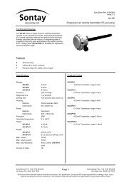
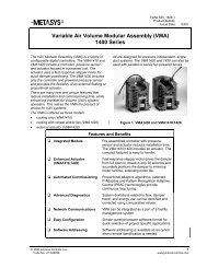
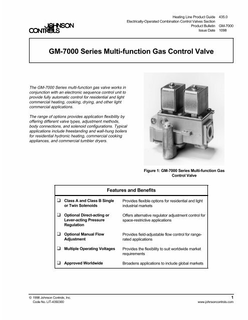
Heating Line Product Guide 435.0Electrically-Operated Combination <strong>Control</strong> <strong>Valve</strong>s SectionProduct Bulletin <strong>GM</strong>-<strong>7000</strong>Issue Date 1098<strong>GM</strong>-<strong>7000</strong> <strong>Series</strong> <strong>Multi</strong>-<strong>function</strong> <strong>Gas</strong> <strong>Control</strong> <strong>Valve</strong>The <strong>GM</strong>-<strong>7000</strong> <strong>Series</strong> multi-<strong>function</strong> gas valve works inconjunction with an electronic sequence control unit toprovide fully automatic control for residential and lightcommercial heating, cooking, drying, and other lightcommercial applications.The range of options provides application flexibility byoffering different valve types, adjustment methods,body connections, and solenoid configurations. Typicalapplications include freestanding and wall-hung boilersfor residential hydronic heating, commercial cookingappliances, and commercial tumbler dryers.Figure 1: <strong>GM</strong>-<strong>7000</strong> <strong>Series</strong> <strong>Multi</strong>-<strong>function</strong> <strong>Gas</strong><strong>Control</strong> <strong>Valve</strong>Features and Benefits❑ Class A and Class B Singleor Twin Solenoids❑ Optional Direct-acting orLever-acting PressureRegulation❑ Optional Manual FlowAdjustment❑ <strong>Multi</strong>ple Operating Voltages❑ Approved WorldwideProvides flexible options for residential and lightindustrial marketsOffers alternative regulator adjustment control forspace-restrictive applicationsProvides field-adjustable flow control for rangeratedapplicationsProvides the flexibility to suit worldwide marketrequirementsBroadens applications to include global markets© 1998 Johnson <strong>Control</strong>s, Inc. 1Code No. LIT-4350300www.johnsoncontrols.com
Overview<strong>Valve</strong> OperationThe <strong>GM</strong>-<strong>7000</strong> is an on/off valve with spring-loadedseat discs that are operated by a solenoids withprotected rectifiers to ensure quiet operation.When the valve is energized, the solenoid plunger ispulled into the coil, overcoming the force of the closeoffspring and the flow medium pressure. The valve seatdiscs are directly fixed to the plunger stem so the valvefully opens.The plunger is Teflon® coated, providing maintenancefreeoperation under permissible temperature andpressure specifications.<strong>Valve</strong> TypesThe <strong>GM</strong>-<strong>7000</strong> valve is available with either single ortwin Class A or Class B solenoids and either 3/8 inchor 1/2 inch body thread connections.The <strong>GM</strong>-75_ _ models have Class B rated solenoidsand the <strong>GM</strong>-77_ _ models have Class A ratedsolenoids.Adjustment MethodsThe <strong>GM</strong>-<strong>7000</strong> <strong>Series</strong> offers different types of flow orpressure regulator control. Models are available withmanual flow adjustment, direct-acting regulator, andlever-acting regulator control.No AdjustmentThe <strong>GM</strong>-7 _1_ model has a blank plate mounted ontothe bottom of the body casting for applications whereadjustment control is not needed or for applicationswhere separate adjustment control is already provided.Flow AdjustmentThe <strong>GM</strong>-7 _2_ model has manual flow control throughthe use of an adjustable screw. The screw adjusts theposition of an internal flow plug to determine the flowrate through the valve.Regulator AdjustmentThe regulator controls the gas pressure at the valveoutlet by positioning the regulator poppet for selectedthroughput flow and pressure. This is achieved by thevalve outlet pressure acting on the regulatordiaphragm, which balances against the presetregulator spring. Adjustment of the spring compressiondetermines the valve outlet pressure and thethroughput flow rate.The <strong>GM</strong>-7 _3_ model has a direct-acting pressureregulator. The direct-acting regulator operates bymeans of the regulator spring acting directly onto theregulator diaphragm. The direct-acting regulator isadjusted from the underside of the valve.The <strong>GM</strong>-7 _4_ model has a right-handed lever-actingpressure regulator. The lever-acting regulator operatesby means of the regulator spring acting onto a lever toposition the regulator diaphragm. The lever-actingpressure regulator is adjusted from the top of the valvewhen the valve is in the upright position (solenoid coilson top). Right-handed orientation is determined by theposition of the adjustment when looking into the inletconnection of the valve.The <strong>GM</strong>-7 _5_ model has a left-handed lever-actingpressure regulator. The lever-acting regulator operatesby means of the regulator spring acting onto a lever toposition the regulator diaphragm. The lever-actingregulator is adjusted from the top of the valve when thevalve is in the upright position (solenoid coils on top).Left-handed orientation is determined by the position ofthe adjustment when looking into the inlet connectionof the valve.2 <strong>GM</strong>-<strong>7000</strong> <strong>Series</strong> <strong>Multi</strong>-<strong>function</strong> <strong>Gas</strong> <strong>Control</strong> <strong>Valve</strong> Product Bulletin
Range of RegulationPressure Regulator Models (<strong>GM</strong>-7 _3_,<strong>GM</strong>-7 _4_, and <strong>GM</strong>-7 _5_)The <strong>GM</strong>-7 _3_ model has an adjustable direct-actingpressure regulator and the <strong>GM</strong>-7 _4_ and <strong>GM</strong>-7 _5_models have an adjustable lever-acting pressureregulator. Both the direct-acting and lever-actingpressure regulators have the following pressure range:• Natural gas: 5 to 15 mbar (2 to 6 in. W.C.)• Liquid Petroleum (LP) gas: 22.5 to 30 mbar(9 to 12 in. W.C.)Table 1: Range of Regulation for Pressure Regulator Models<strong>Valve</strong> ModelFlange Thread Size Q minimumQ maximuminch M 3 /h cf/h m 3 /h cf/h<strong>GM</strong>-7 _3_,<strong>GM</strong>-7_4_, and<strong>GM</strong>-7_5_3/81/20.2830.28310102.832.83100100Note: 1 m 3 /h = 10.67 kW (1 cf/h = 1,000 Btu/hr) natural gas at 0.64 sp grFor LP flow rates, see Figures 2 through 4.<strong>GM</strong>-<strong>7000</strong> <strong>Series</strong> <strong>Multi</strong>-<strong>function</strong> <strong>Gas</strong> <strong>Control</strong> <strong>Valve</strong> Product Bulletin 3
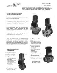
<strong>Valve</strong> Flow Capacity<strong>GM</strong>-752_ and <strong>GM</strong>-772_ Manual Flow Adjustment ModelsPressure Dropmbar100705040303/8 inch1/2 inchPressure Dropin. W.C.40.028.020.016.012.0208.06.010754324.02.82.01.61.00.8Air(sp gr = 1.0)10.431 2 3 4 5 6 8 10 20 30 40 50 100 m/hNatural <strong>Gas</strong>(sp gr = 0.64)1.5 2 3 4 6 10 20 40 60 1003m/h50 100 200 300 500 1000 2000 3000cf/hLP - Propane(sp gr = 1.53)1 2 3 4 6 10 20 40 60 1003m/h40 50 100 200 300 500 1000 2000 3000cf/hCapacityFigure 2: Maximum Flow Capacity4 <strong>GM</strong>-<strong>7000</strong> <strong>Series</strong> <strong>Multi</strong>-<strong>function</strong> <strong>Gas</strong> <strong>Control</strong> <strong>Valve</strong> Product Bulletin
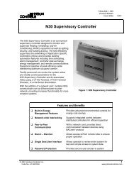
<strong>GM</strong>-753_ and <strong>GM</strong>-773_ Direct-acting Pressure Regulator ModelsPressure Dropmbar10070504030Pressure Dropin. W.C.40.028.020.016.012.0208.06.010754324.02.82.01.61.00.8Air(sp gr = 1.0)11 2 3 4 5 6 8 10 20 30 40 50 1000.43m/hNatural <strong>Gas</strong>(sp gr = 0.64)1.5 2 3 4 6 10 20 40 60 1003m/h50 100 200 300 500 1000 2000 3000cf/hLP - Propane(sp gr = 1.53)1 2 3 4 6 10 20 40 60 1003m/h40 50 100 200 300 500 1000 2000 3000cf/hCapacityFigure 3: Maximum Flow Capacity<strong>GM</strong>-<strong>7000</strong> <strong>Series</strong> <strong>Multi</strong>-<strong>function</strong> <strong>Gas</strong> <strong>Control</strong> <strong>Valve</strong> Product Bulletin 5
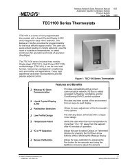
Dimensions60.24301.18240.95160.630.24 702.76 6120.47120.47481.891054.13120.47120.47Figure 5: <strong>Valve</strong> with Manual Flow Adjustment and 3-pin Class B (9.5 VA) Coils, mm (in.)<strong>GM</strong>-<strong>7000</strong> <strong>Series</strong> <strong>Multi</strong>-<strong>function</strong> <strong>Gas</strong> <strong>Control</strong> <strong>Valve</strong> Product Bulletin 7
60.24301.1821.50.85150.600.24 702.76 6200.79381.5622.4450.21054.13Figure 6: <strong>Valve</strong> with Direct-acting Pressure Regulator and 2-pinClass B (9.5 VA) Coils, mm (in.)8 <strong>GM</strong>-<strong>7000</strong> <strong>Series</strong> <strong>Multi</strong>-<strong>function</strong> <strong>Gas</strong> <strong>Control</strong> <strong>Valve</strong> Product Bulletin
90.35391.54OptionalPush-onElectricalConnectorSocket562.21301.18230.91441.73752.95200.79361.421054.13501.97Figure 7: <strong>Valve</strong> with Lever-acting Pressure Regulator and 3-pin Class A (16 VA) Coils, mm (in.)(Right-hand Orientation Shown)M ountingThe <strong>GM</strong>-<strong>7000</strong> valve may be mounted on a horizontalmanifold with the magnetic operators (solenoid coils)pointed up (vertical) or in any position not exceeding90 o from the vertical.The valve may also be mounted on a verticalmanifold in any position around its axis (seeFigure 8). Do not install the solenoid actuator upsidedown. Install vertically wherever possible.90° Maximumfrom Vertical90° Maximumfrom VerticalLimited Horizontal and VerticalNote: 85 mm (3.35 in.) Maximum Swing RadiusFigure 8: <strong>GM</strong>-<strong>7000</strong> <strong>Valve</strong> Mounting Position<strong>GM</strong>-<strong>7000</strong> <strong>Series</strong> <strong>Multi</strong>-<strong>function</strong> <strong>Gas</strong> <strong>Control</strong> <strong>Valve</strong> Product Bulletin 9
Ordering Information<strong>GM</strong>- 7 - - - - - - 0 0Application SpecialsSolenoid Coil Type1 = 230 VAC; 50/60 Hz; 2-pin5 = 230 VAC; 50/60 Hz; 3-pin7 = 110/120 VAC; 50/60 Hz; 3-pin8 = 24 VAC; 50/60 Hz; 3-pinConfiguration1 = Single Solenoid; Pilot <strong>Valve</strong> (First Seat)2 = Single Solenoid; Main <strong>Valve</strong> (Second Seat)3 = Twin SolenoidsBody Connections1 = Inlet 3/8-inch Rp + Flange Holes : Outlet 3/8-inch Rp + Flange Holes2 = Inlet 1/2-inch Rp + Flange Holes : Outlet 1/2-inch Rp + Flange Holes3 = Inlet 3/8-inch NPT + Flange Holes : Outlet 3/8-inch NPT + Flange Holes4 = Inlet 1/2-inch NPT + Flange Holes : Outlet 1/2-inch NPT + Flange Holes<strong>Control</strong> Option1 = None2 = Manual Flow Adjuster3 = Pressure Regulator; Direct-acting4 = Pressure Regulator; Right-handed Lever-acting5 = Pressure Regulator; Left-handed Lever-actingReverse Pressure Rating5 = Class B7 = Class A<strong>Gas</strong> <strong>Multi</strong>-<strong>function</strong>al <strong>Valve</strong>Figure 9: <strong>Valve</strong> Ordering Matrix10 <strong>GM</strong>-<strong>7000</strong> <strong>Series</strong> <strong>Multi</strong>-<strong>function</strong> <strong>Gas</strong> <strong>Control</strong> <strong>Valve</strong> Product Bulletin
AccessoriesTable 2: AccessoriesDescriptionPart NumberLow-profile CoverGO-9403-0000Electrical Plug and Socket Connector for 9.5 VA 3-pin SolenoidGO-9104-0000Electrical Plug and Socket Connector for 16 VA 3-pin SolenoidGO-9101-00007/16 in. x 24 Pilot Blank Plug GO-9052-00006 mm Breakaway Pilot Compression Fitting GO-9060-00004 mm Breakaway Pilot Compression Fitting GO-9661-00001/4 in. Breakaway Pilot Compression Fitting GO-9662-0000Conversion Kit for Non-regulation<strong>GM</strong>-70-CBPConversion Kit with LP Spring<strong>GM</strong>-70-CLPRepair and ReplacementField repairs must not be made except forreplacement of the solenoid coils.Table 3: Replacement Solenoid CoilsDescriptionFor a replacement coil or valve, contact the nearestJohnson <strong>Control</strong>s representative or the originalequipment manufacturer.Part Number24 VAC; 50/60 Hz; 3-pin Class B (9.5 VA) Coil GO-9622-000024 VAC; 50/60 Hz; 3-pin Class A (16 VA) Coil GO-9632-0000110/120 VAC; 50/60 Hz; 3-pin Class B (9.5 VA) Coil GO-9621-0000110/120 VAC; 50/60 Hz; 3-pin Class A (16 VA) Coil GO-9631-0000230 VAC; 50/60 Hz; 2-pin Class B (9.5 VA) Coil GO-9610-0000230 VAC; 50/60 Hz; 3-pin Class B (9.5 VA) Coil GO-9620-0000230 VAC; 50/60 Hz; 3-pin Class A (16 VA) Coil GO-9630-0000<strong>GM</strong>-<strong>7000</strong> <strong>Series</strong> <strong>Multi</strong>-<strong>function</strong> <strong>Gas</strong> <strong>Control</strong> <strong>Valve</strong> Product Bulletin 11
SpecificationsProduct <strong>GM</strong>-<strong>7000</strong> <strong>Series</strong> <strong>Multi</strong>-<strong>function</strong> <strong>Gas</strong> <strong>Control</strong> <strong>Valve</strong>Media 1st (Manufactured <strong>Gas</strong>), 2nd (Natural <strong>Gas</strong>), and 3rd (LP <strong>Gas</strong>) Family <strong>Gas</strong>esMaximum Operating Pressure North America: 1/2 psiEurope: 100 mbar; Class A (EN 161)50 mbar; Class B (EN 161)Maximum Differential Pressure 20 mbar (8 in. W.C.)Reverse Pressure Ratings 150 mbar (60 in. W.C.) Minimum; Class A (EN 161)50 mbar (20 in. W.C.) Minimum; Class B (EN 161)Regulator Classification Direct-acting Regulator: Class B (EN 88)Lever-acting Regulator: Class C (EN 88)Direct-acting or Lever-acting Natural <strong>Gas</strong>:5 to 15 mbar (2 to 6 in. W.C.)Regulator Pressure Range LP <strong>Gas</strong>:22.5 to 30 mbar (9 to 12 in. W.C.)Permissible Ambient Temperature 0 to 70°C (32 to 158°F)Body Connections 3/8 or 1/2 in. NPT or Rp with Flange Connection Holes (M4 x 0.7 mm Pitch x 6 mm Deep)<strong>Valve</strong> Torsion Group Group 2 (EN 88 and EN 161)Pressure Taps 9.0 mm (0.35 in.) Outlet Tap Spigot; Optional 1/8 in. NPT or Rp Inlet TapPilot Connection Optional 6 mm, 4 mm, 1/4 in., or blank plugDimensions (H x W x D) See Figures 5 through 7.Materials Body: Die-cast AluminumDiaphragms and Seals: Nitrile RubberDirt Strainer 0.5 mm (0.02 in.) meshOperating Time Rating 100% Continuous<strong>Valve</strong> Timings Closing Time: < 1 SecondOpening Time: < 1 SecondDead Time:< 1 SecondPower Ratings 16 VA per Coil; Class A (EN 161)9.5 VA per Coil; Class B (EN 161)Electrical Connections 3-pin Solenoid Coil: 2 x 6.35 mm (1/4 in.) Terminals + 6.35 mm (1/4 in.)Earth Ground Terminal2-pin Solenoid Coil: 2 x 6.35 mm (1/4 in.) Terminals + Earth GroundScrew ConnectionCoil Insulation Class Class FAgency Listings IAS (AGA/CGA) Certificate Number C0197003EC Type Examination Certificate Number C87AP57Australian <strong>Gas</strong> Association Certificate Number 4518Specification Standards EN 88, EN 126, EN 161, and EN 12067-1Standards Complying with the EMC DirectiveStandards Complying with the Low Voltage DirectiveCanadian Standard CAN 1-6.3 and 1-6.5ANSI Standards, Z21.21 and Z21.78Australian Standard 209, Class 2 to AGA 214The performance specifications are nominal and conform to acceptable industry standards. For application at conditions beyond thesespecifications, consult the local Johnson <strong>Control</strong>s office. Johnson <strong>Control</strong>s, Inc. shall not be liable for damages resulting frommisapplication or misuse of its products.Refer to the <strong>GM</strong>-<strong>7000</strong> <strong>Series</strong> Technical Bulletin (LIT-121910) for necessary information on the installation, use, and servicing of this product.<strong>Control</strong>s Groupwww.johnsoncontrols.com507 E. Michigan Street FAN 435.0P.O. Box 423Heating Line Product GuideMilwaukee, WI 53201Printed in U.S.A.12 <strong>GM</strong>-<strong>7000</strong> <strong>Series</strong> <strong>Multi</strong>-<strong>function</strong> <strong>Gas</strong> <strong>Control</strong> <strong>Valve</strong> Product Bulletin