Miniature High Heat Flux Heat Pipes for Cooling of Electronics
Miniature High Heat Flux Heat Pipes for Cooling of Electronics
Miniature High Heat Flux Heat Pipes for Cooling of Electronics

Create successful ePaper yourself
Turn your PDF publications into a flip-book with our unique Google optimized e-Paper software.
ISO9001 & AS9100CertifiedADVANCED COOLING TECHNOLOGIES, INC.Innovations in Action_____________________________________________________they are not suitable <strong>for</strong> applications requiring operation beyond 150°C. With the vapor pressurerising with temperature, copper is not an ideal envelope material because <strong>of</strong> its low yield strengthand high density. ACT has run life tests to prove the compatibility <strong>of</strong> stronger envelope materials<strong>for</strong> high temperature water heat pipes. As shown in Table 3, these results are ongoing and lastrecording date was April 15 2010.EnvelopeMaterialCp-TiC22C2000B3Table 2 ACTs Life Test Data <strong>for</strong> Intermediate TemperaturesWorking FluidAlBr 3 GaCl 3 SnCl 4 TiCl 4 TiBr 4 TherminolΔT - 99.5* - - -0.6K 125 Khours - 1272 - - 1344 1344ΔT 3.7 K132.1 K 7.0 K - -Failedhours 1272 1464 1464 - -ΔT 0.6 K116.2 K 3.3 K - -Failedhours 1272 1464 1464 - -ΔT 1.8 K31.5 K 57.2 K - -Failedhours 312 1464 1464 - -Table 3 <strong>High</strong> Temperature Water <strong>Heat</strong> <strong>Pipes</strong>Wall MaterialWick MaterialOperating OperatingTemperature HoursMonel K 500 200 x 200 Monel 400 Screen550 & 500 K(277 & 227°C)45,336CP-2 Ti150 x 150 CP-Ti Screen550 & 500 K(277 & 227°C)45,336CP-2 Ti Sintered Titanium 550 K (277 °C) 36,941CP-2 Ti 100 x 100 Cp-Ti Screen 550 K (277 °C) 34,256Cp-2 Ti 100 x 100 Cp-Ti Screen 550 K (277 °C) 36,941Grade 5 Ti 100 x 100 Cp-Ti Screen 550 K (277 °C) 36,941Grade 7 Ti 100 x 100 Cp-Ti Screen 550 K (277 °C) 36,941Grade 9 Ti 100 x 100 CP-Ti Screen 550 K (277 °C) 32,784Monel 400 120 x 120 Monel 400 Screen 550 K (277 °C) 32,280Monel K 500 120 x 120 Monel 400 Screen 550 K (277 °C) 31,440Monel 400 -100+170 Mesh Monel 400 550 K (277 °C) 30,192Monel K 500 -100+170 Mesh Monel 400 550 K (277 °C) 30,552<strong>Heat</strong> Pipe Per<strong>for</strong>mance LimitsUnderstanding and accurately predicting the various heat pipe per<strong>for</strong>mance limitations areessential to designing a reliable heat pipe. The design should take into account operating1046 New Holland Avenue, Lancaster, PA 17601, USA717-295-6061 (Phone), 717-295-6064 (Fax)www.1-ACT.com
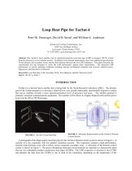
ISO9001 & AS9100CertifiedADVANCED COOLING TECHNOLOGIES, INC.Innovations in Action_____________________________________________________orientation, temperature range and other possible adverse conditions such as shock, vibration andacceleration loading.Figure 1 shows the various heat pipe limitations <strong>for</strong> a typical copper/water heat pipe. Theselimitations are a function <strong>of</strong> the operating temperature, due to the change in the fluid propertiesas a function <strong>of</strong> temperature. It is important to ensure that the appropriate per<strong>for</strong>mance limitcurve adequately cover the per<strong>for</strong>mance requirement <strong>for</strong> the entire specified temperature range.Qcap (W)1401301201101009080706010" Copper / Water <strong>Heat</strong> Pipe3" Evaporator and CondenserCapilary Limit - 3" Gravity AidedFlooding LimitSonic LimitViscous LimitCapilary Limit - 3" Against Gravity504030201000 25 50 75 100 125 150 175 200 225Operating Temperature (C)Figure 1 <strong>Heat</strong> Pipe Per<strong>for</strong>mance Limits <strong>for</strong> 10” Long copper/water heat pipe. Two capillary curvesshow the effect <strong>of</strong> orientation.OrientationAs shown in Figure 1, the heat pipe operating orientation affects the amount <strong>of</strong> power it cantransfer. However, once a heat pipe design has been developed to handle the worst caseorientation, changing orientations has little effect on its thermal resistance. The physics behindthe gravity orientation effect is described in the following pressure balance equation:where:ΔPc ≥ ΔPv + ΔPl + ΔPg eq. 1.01046 New Holland Avenue, Lancaster, PA 17601, USA717-295-6061 (Phone), 717-295-6064 (Fax)www.1-ACT.com
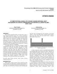
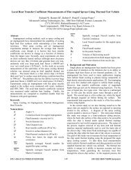
ISO9001 & AS9100CertifiedADVANCED COOLING TECHNOLOGIES, INC.Innovations in Action_____________________________________________________ΔPc = Capillary pressure gradient generated by the wick structure =2σ cosθeq. 1.1r cΔPv = Pressure drop <strong>of</strong> the vapor flow inside the heat pipeΔPl = Pressure drop <strong>of</strong> the liquid flow inside the wick structureΔPg = Gravity head upon the liquid can be positive or negative depending on the heat pipeorientationEquation 1.0 states that <strong>for</strong> a heat pipe to operate properly, the capillary pressure gradient mustbe able to overcome the pressure drops in the vapor and liquid flows and the adverse gravityhead. Depending on the heat pipe orientation, the gravity head may be beneficial or adverse. Incases where the heat pipe’s evaporator is below the condenser, the heat pipe can transfer morepower because the gravity head aids in the liquid flow from the condenser to the evaporator. Incases where the evaporator is above the condenser, the gravity head works against the liquidreturn to the evaporator, consequently lowering the heat transfer capability <strong>of</strong> a given wickdesign. It should be pointed out that the thermal resistance <strong>of</strong> the heat pipe is independent <strong>of</strong> theorientation as long as the heat pipe operates within the capillary limit.For most terrestrial applications, the capillary limit is <strong>of</strong>ten the controlling limit, because <strong>of</strong> thepotential adverse effect on the liquid return to the evaporator due to gravity. The capillary limit isa function <strong>of</strong> the wick design, more specifically the wick’s pore radius and permeability. Bothsintered powder metal and screen wicks are available in a variety <strong>of</strong> pore sizes. The permeabilityis inversely proportional to the pore size <strong>for</strong> both types <strong>of</strong> wicks. ACT uses in-house heat pipeper<strong>for</strong>mance prediction tools to assure our heat pipes exceed the design requirements.Shock and VibrationACT has substantial experience in designing, fabricating and testing heat pipe assemblies tovarious shock and vibration loadings. ACT has in house mechanical shock and vibration testequipment as shown in Figure 2. ACT’s heat pipes and loop heat pipes have been tested todiverse shock and vibration conditions including:- 4,500 lbf <strong>for</strong>ce sustained vibration loads- Up to 9,000 lbf shock loads- 0-3,000 Hz Frequency Range- Over 100g's peak acceleration- Vibration: Sine, Random, Sine on Random, Random on Random- Shock: Haversine, Half-Sine, Saw-Tooth, & Trapezoid- Replication <strong>of</strong> Measured Field Data- Gunfire Vibration- Shock Response SpectrumACT’s shock test rig can produce a peak acceleration <strong>of</strong> G pk =123g. The vibration capabilitiesinclude a frequency <strong>of</strong> 267 Hz, G rms =24g, and G pk =45g. Examples <strong>of</strong> shock and vibration testpr<strong>of</strong>iles are shown in Figure 3.1046 New Holland Avenue, Lancaster, PA 17601, USA717-295-6061 (Phone), 717-295-6064 (Fax)www.1-ACT.com
ISO9001 & AS9100CertifiedADVANCED COOLING TECHNOLOGIES, INC.Innovations in Action_____________________________________________________Figure 2. (a) Shock Test Table (Left). (b) Vibration Test Table (Right).Figure 3. (a) Shock Amplitude vs. Time. (b) Acceleration vs. TimeTesting has confirmed that vibration loading has little or no impact on the per<strong>for</strong>mance <strong>of</strong> ACT’sheat pipes. Shock and vibration testing showed no evidence <strong>of</strong> overstress or fatigue on the heatpipes or solder joints. Some examples <strong>of</strong> vibration tests are listed below:• Tac-Sat 4 Loop <strong>Heat</strong> Pipe Assembly. This assembly was tested to both transport andlaunch acceleration and vibration loads. ACT designed the system to survive customerdefined Mass-Acceleration Curve up to 60 G’s, and 3 dimensional Random VibrationSpectrum. The design was validated by 3-axis random vibration testing. The predictedand actual responses matched well.1046 New Holland Avenue, Lancaster, PA 17601, USA717-295-6061 (Phone), 717-295-6064 (Fax)www.1-ACT.com
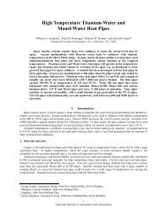
ISO9001 & AS9100CertifiedADVANCED COOLING TECHNOLOGIES, INC.Innovations in Action_____________________________________________________• Hybrid Two Phase Loop System. ACT tested a pumped two phase system with internalwick components to military vehicle shock and vibration requirements. Figure 4 (a)shows the PSD pr<strong>of</strong>ile <strong>of</strong> the body and frame in a Future Combat Systems (FCS)-likemilitary vehicle. The PSD curve produces a maximum vibration level <strong>of</strong> about 5 G rms .Figure 4 (b) shows the shock pr<strong>of</strong>ile <strong>of</strong> the same vehicle with a half-sine pulse <strong>of</strong> 10 G's<strong>for</strong> 50~75 ms. This thermal per<strong>for</strong>mance was identical be<strong>for</strong>e and after the tests.• <strong>Heat</strong> Pipe Loop Assembly- This assembly was tested to the shock and vibrationspecifications shown in Figure 4 under full thermal loading with no degradation inper<strong>for</strong>mance during testing.(a)(b)Figure 4 (a) Vibration and (b) Shock Pr<strong>of</strong>iles <strong>of</strong> FSC-Variant Body/Frame Mounted ComponentsAccelerationAs long as the wick’s capillary <strong>for</strong>ce is greater than the pressure drops and the accelerationloading, the heat pipe will per<strong>for</strong>m properly under various acceleration loadings. However,extremely large adverse acceleration loadings may overwhelm the wick’s capillary capability,de-priming the wick or eventually causing the wick to dry out.If the acceleration is <strong>for</strong> short durations, the wick structure will re-prime and the thermaltransient may be within an allowable range. An alternative approach will be required if thetransients are <strong>for</strong> longer durations. If the axis and direction <strong>of</strong> acceleration are known the heatpipes can be configured such that acceleration helps return the condensed fluid “gravity aided”.If the acceleration axis is unknown heat pipes can be arranged in pairs so that regardless <strong>of</strong> theacceleration vector one heat pipe will always be “gravity aided”.Frozen Start UpMany military and commercial applications specify temperatures ranging from -45˚C to + 70˚C.Water heat pipes are typically used in these applications because <strong>of</strong> their proven reliability and1046 New Holland Avenue, Lancaster, PA 17601, USA717-295-6061 (Phone), 717-295-6064 (Fax)www.1-ACT.com
ISO9001 & AS9100CertifiedADVANCED COOLING TECHNOLOGIES, INC.Innovations in Action_____________________________________________________capability. The heat pipes must be able to operate with full capacity at the higher end <strong>of</strong> thetemperature range to provide the required cooling. Frozen start up can be an issue if the systemthermal mass and heat transfer are such that the fluid in the evaporator is thawed and vaporizedby the heat input, travels to the condenser and freezes there. This could result in the depletion <strong>of</strong>fluid in the evaporator, eventually shutting down the heat pipe.This is a system design issue and not typically a heat pipe limitation. There are four ways toaddress this issue. First, design the system so that frozen start up is not an issue. In other words,the input power and vapor transport are sufficient to thaw the entire system. Second, use activecontrols such as turning <strong>of</strong>f fans to limit heat transfer in freezing conditions. Third, design in asecondary heat transfer mechanism so that the heat pipes are not needed to prevent device fromoverheating in freezing ambient conditions. Fourth, add a predetermined amount <strong>of</strong> NCG to theheat pipe to ensure “orderly” freezing and thawing. Options one and three are typical in mostassemblies by default, but can be assured through analysis and testing.Thermal Cycling<strong>Heat</strong> pipes utilize a wick structure to transport the liquid working fluid from the condenser to theevaporator. When properly made, the working fluid fully saturates the wick without making apuddle <strong>of</strong> excess fluid. With the fluid completely contained within the wick, it is not able tobridge the gap across the inside diameter <strong>of</strong> the heat pipe. This allows multiple freeze thawcycles to occur without heat pipe de<strong>for</strong>mation. A variety <strong>of</strong> working fluids may be used whichdirectly affects the freezing temperature <strong>of</strong> the heat pipe.ACT routinely subjects heat pipes to thermal cycling to meet customer requirements. Typicalfreeze thaw tests are conducted from temperatures ranging from -20 to +20°C and -45 to+125°C. ACT has tested heat pipes up to 1,200 cycles, but 50-300 cycles are a more standardpractice. <strong>Heat</strong> pipes may be thermally cycled prior to installation into assemblies. <strong>Heat</strong> pipeassemblies are also thermally cycled in assembled units to assure system level per<strong>for</strong>mance.Below are three examples:• <strong>Heat</strong> <strong>Pipes</strong>. ACT conducted tests to collect data on heat pipe thermal cyclingsurvivability. The data set <strong>for</strong> these experiments used both fabricated flattened and bent4mm heat pipes as well as 0.25” diameter copper water heat pipes. <strong>Heat</strong> pipes wereexposed to as many as 1200 freeze thaw cycles without de<strong>for</strong>mation or per<strong>for</strong>mancedegradation• AlSiC HiK Plates. This project developed an innovative low-CTE heat spreader byembedding heat pipes into AlSiC plates. These plates showed similar effective thermalconductivity be<strong>for</strong>e and after 100 freeze/thaw cycles from -55°C to 125°C.• Aluminum HiK Plates. In this project, copper water heat pipes are soldered intoaluminum plates. Prior to fabrication, the heat pipes are screened by being exposed to300 cycles from -20°C to +20°C. Once the assemblies were fabricated, the plates wereexposed to an additional 50 cycles from -40°C to +75°C in two different orientations1046 New Holland Avenue, Lancaster, PA 17601, USA717-295-6061 (Phone), 717-295-6064 (Fax)www.1-ACT.com
ISO9001 & AS9100CertifiedADVANCED COOLING TECHNOLOGIES, INC.Innovations in Action_____________________________________________________(100 cycles total) to assure freeze/thaw survivability. Figure 5 shows the temperaturepr<strong>of</strong>ile <strong>of</strong> plates exposed to thermal cycling. This is a 100% test requirement which allassemblies must pass prior to shipping. All plates are checked <strong>for</strong> any signs <strong>of</strong> thermal ormechanical degradation.80.0060.0040.00°C20.000.000-20.00-40.003/24/20109:58:00.000 AM12:00:00 (h:min:s)2 h/DivFigure 5: Freeze/Thaw cycle data3/24/20109:58:00.000 PMSummaryACT has experienced engineers to design, analyze, and integrate heat pipe based thermalsolutions <strong>for</strong> a wide range <strong>of</strong> applications. Our expertise includes designing optimal heat pipesbased on proven compatible fluids, analyzing heat pipe limitations, and manufacturing heat pipesto the highest quality standards. ACT also has extensive testing capabilities including shock,vibration, acceleration, and freeze/thaw tests. ACT has designed, manufactured and deliveredheat pipe products <strong>for</strong> numerous commercial, military and aerospace systems.References:1 <strong>Heat</strong> <strong>Pipes</strong>, Dunn & Reay. Fourth Edition. Ox<strong>for</strong>d, England: Elsevier Science Ltd., 1994. 127-140.2 Intermediate Temperature Fluids Life Tests - Experiments, William Anderson, et al., 2007 InternationalEnergy Conversion Engineering Conference, St. Louis, MO, June 2007.3 Intermediate Temperature Fluids Life Tests - Theory, Calin Tarau, et al., Space Technology andApplications International Forum (STAIF), Albuquerque, NM, February 11 - 15, 2007.4<strong>High</strong> Temperature Titanium-Water and Monel-Water <strong>Heat</strong> <strong>Pipes</strong>, William Anderson, et al., 2006International Energy Conversion Engineering Conference, San Diego, CA, June 2006.5 <strong>High</strong>-Temperature Water <strong>Heat</strong> <strong>Pipes</strong>, David Sarraf and William Anderson, IMAPS InternationalConference on <strong>High</strong> Temperature <strong>Electronics</strong>, Santa Fe, NM, May 15 - 18, 20061046 New Holland Avenue, Lancaster, PA 17601, USA717-295-6061 (Phone), 717-295-6064 (Fax)www.1-ACT.com