Loop Heat Pipe for TacSat-4 - Advanced Cooling Technologies, Inc.
Loop Heat Pipe for TacSat-4 - Advanced Cooling Technologies, Inc.
Loop Heat Pipe for TacSat-4 - Advanced Cooling Technologies, Inc.

You also want an ePaper? Increase the reach of your titles
YUMPU automatically turns print PDFs into web optimized ePapers that Google loves.
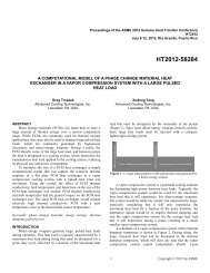
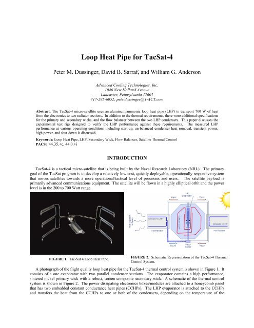
<strong>Loop</strong> <strong>Heat</strong> <strong>Pipe</strong> <strong>for</strong> <strong>TacSat</strong>-4Peter M. Dussinger, David B. Sarraf, and William G. Anderson<strong>Advanced</strong> <strong>Cooling</strong> <strong>Technologies</strong>, <strong>Inc</strong>.1046 New Holland AvenueLancaster, Pennsylvania 17601717-295-6052; pete.dussinger@1-ACT.comAbstract. The <strong>TacSat</strong>-4 micro-satellite uses an aluminum/ammonia loop heat pipe (LHP) to transport 700 W of heatfrom the electronics to two radiator sections. In addition to the thermal requirements, there were additional specifications<strong>for</strong> the primary and secondary wicks, and the flow balancer between the two LHP condensers. This paper discusses theexperimental test rigs designed to verify the LHP per<strong>for</strong>mance against these requirements. The measured LHPper<strong>for</strong>mance at various operating conditions including start-up, un-balanced condenser heat removal, transient power,high power, and shut-down is discussed.Keywords: <strong>Loop</strong> <strong>Heat</strong> <strong>Pipe</strong>, LHP, Secondary Wick, Flow Balancer, Satellite Thermal ControlPACS: 44.35.+c, 44.0.+iINTRODUCTION<strong>TacSat</strong>-4 is a tactical micro-satellite that is being built by the Naval Research Laboratory (NRL). The primarygoal of the <strong>TacSat</strong> program is to develop a relatively low cost, quickly deployable, operationally responsive systemthat moves satellites towards a more operational/tactical level of processes and users. The satellite payload isprimarily advanced communications equipment. The satellite will be flown in a highly elliptical orbit and the powerlevel is in the 200 to 700 Watt range.FIGURE 1. Tac-Sat 4 <strong>Loop</strong> <strong>Heat</strong> <strong>Pipe</strong>.FIGURE 2. Schematic Representation of the <strong>TacSat</strong>-4 ThermalControl System.A photograph of the flight quality loop heat pipe <strong>for</strong> the <strong>TacSat</strong>-4 thermal control system is shown in Figure 1. Itconsists of a one evaporator with two parallel condenser sections. The evaporator contains a high per<strong>for</strong>mance,sintered nickel primary wick with a robust, screen composite secondary wick. A schematic of the thermal controlsystem is shown in Figure 2. The power dissipating electronics boxes/modules are attached to a honeycomb panelthat has two embedded constant conductance heat pipes (CCHPs). The LHP evaporator is attached to the CCHPsand transfers the heat from the CCHPs to one or both of the condensers, depending on the temperature of the
adiators that are attached to the LHP condensers. Each of the two radiator sections is four segments of theoctagonal shaped satellite envelope.TABLE 1. <strong>TacSat</strong>-4 <strong>Loop</strong> <strong>Heat</strong> <strong>Pipe</strong> Design Requirements.Parameter/DescriptionQuantity/MagnitudeOperating Temperature-20 to +50°CSurvival Temperature-70 to +80°CWorking FluidHigh Purity Ammonia<strong>Heat</strong> Transport Capability5 to 700 WattsEffective Thermal Conductance (Pump) ≥120 W/K at 500 WattsOverall LHP Conductance≥70 W/K; 200 to 700 WattsCapillary Pump Length30.5 cm (12 inches)Primary Wick MaterialSintered Nickel PowderPrimary Wick Pore Size ≤ 1.5 µmPrimary Wick Permeability ≥ 1.0 x 10 -14 m 2Primary Wick Thermal Conductivity≤ 10 W/m-KPrimary Wick Outer Diameter2.54 cm (1 inch)Secondary Wick Static Height Capability ≥ 1.6 cm (0.63 inches)Secondary Wick Transport Capability ≥ 30.5 W-m (1200 W-in)Secondary Wick MaterialStainless Steel Screen CompositeCondenser GeometryTwo (2) Parallel PathsCapillary Flow Balancer Vapor Hold Off≥ 1000PaCapillary Flow Balancer Liquid Delta P ≤ 1000 Pa at 0.7 grams/sec flowCapillary Pump Material6063 AluminumCompensation Chamber Material316 Stainless SteelTransport Line Material316 Stainless SteelCondenser Section Material6063 Aluminum ExtrusionThe LHP uses ammonia as theworking fluid and was designed totransfer up to 700 Watts. Theevaporator body and condenser lines arealuminum. The transport lines andcompensation chamber are stainlesssteel. Friction welded bi-metaltransition joints are used to couple thestainless steel sections to the aluminumsections. The primary wick is sinterednickel powder and the secondary wick isa stainless steel screen structure. Thecomplete list of design requirements isshown in Table 1. The <strong>TacSat</strong>-4 LHPwas successfully designed,manufactured, tested, and then deliveredto NRL in February of 2008. Thesatellite is scheduled to launch in mid tolate 2009.PRIMARY WICKThe primary wick <strong>for</strong> the <strong>TacSat</strong>-4 LHP wasmanufactured using sub-micron sized nickel powders. Aphotograph of two sintered and fully machined primary wicksis shown in Figure 3. The primary wick was tested todetermine its porosity, pore radius, and permeability. Asample section of the wick material, taken from one end ofthe pre-machined wick was also tested <strong>for</strong> thermalconductivity. Table 2 compares the actual wick properties tothe specifications.FIGURE 3. LHP Primary Wick.TABLE 2. Primary Wick Properties – Specification versus Actual.Property Specification ActualPorosity n/a 75%Pore Radius ≤ 1.5 µm 1.4 µmPermeability ≥ 1.0 x 10 -14 m 2 2.0 x 10 -14 m 2Thermal Conductivity ≤ 10 W/m-K 5.5 W/m-KThe wick thermal conductivity test fixture is shown in Figure 4. A known heat load is applied to the wicksample by electrical resistance cartridge heaters embedded in the “hot end” copper rod. The heat removal isaccomplished by a water cooled “cold end” copper rod. Thermocouples are installed in the cold and hot rods alongthe heat flow path. The temperature between the thermocouples, the cross sectional area of the rod, and the thermal
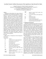
conductivity of the rod material are used to calculate the power being transferred along the length of the rod.Careful evaluation and correction <strong>for</strong> the interface resistances is factored in to achieve an accurate result.The wick pore radius test fixture is shown in Figure 5. The wick sample is saturated with methanol, and has athin layer of methanol above it. The nitrogen pressure in the lower chamber is increased until a bubble breaksthrough the top of the wick. Pore radius and permeability measurements were made at several times during themanufacturing process. The first measurement is taken using a sample of the sintered blank. The secondmeasurement is taken on the as-machined wick be<strong>for</strong>e installation into the pump body. And, the third and finalmeasurement is taken after the wick has been inserted into the pump body and the compensation chamber end seal iscompleted. In all cases, the wick exceeded the capillary and flow resistance requirements <strong>for</strong> this application.FIGURE 4. Wick Thermal Conductivity Test Fixture.FIGURE 5. Wick Pore Radius Test Fixture.SECONDARY WICKSecondary wicks are used to hydraulically link the fluid in the compensation chamber to the primary wick in theevaporator. This is important in both steady state and transient situations. For example, under steady state operatingconditions the inner diameter of the primary wick is at a slightly higher temperature than the saturation temperaturein the compensation chamber. This causes a smallMethanolPoolSecondaryWick<strong>Heat</strong>ed LandSecondaryWick<strong>Heat</strong>erBlockVapor VentPassagesCartridge <strong>Heat</strong>erThermocouplesFIGURE 6. Secondary Wick Per<strong>for</strong>mance Testing.FIGURE 7. Cross-Section of <strong>Heat</strong>er BlockShowing Vapor Vents and <strong>Heat</strong>ed Lands.portion of the heat input to the primary wick to be “backconducted” to the compensation chamber, through twophaseevaporation and condensation, similar to aconventional heat pipe. This is often referred to as a“heat leak”. Without a secondary wick to transfer theequivalent amount of working fluid from thecompensation chamber back to the primary wick, theprimary wick would become starved <strong>for</strong> fluid andultimately result in failure (overheating). Certaintransient conditions, such as an instantaneous powerchange and/or rapid condenser temperature change canalso cause an imbalance between the liquid returning from thecondenser section and the liquid being removed from the primarywick. During these transients, the secondary wick is required tomake up the mass flow rate difference by transferring sufficientliquid from the compensation chamber to the primary wick.NRL evaluated the potential transient conditions and provided thespecification <strong>for</strong> the LHP secondary wick: 30.5 W-m (1200 W-in)of transport capability at a 2° adverse tilt angle in a 1-genvironment. In this application, the primary wick is 30.5cm (12inches) long and the total wicking or liquid flow length (primarywick + transition + compensation chamber) is approximately 45.7cm (18 inches) long. There<strong>for</strong>e, the secondary wick must becapable of 30.5 W-m against an adverse static height of 1.6 cm
(0.63 inches). The capability of the secondary wick had to be demonstrated prior to final assembly of theevaporator body.The secondary wick transport capability was measured <strong>for</strong> both the stand-alone wick, and after the secondarywick was integrated into the primary wick. Figure 6 shows the secondary wick being tested in a stand-alonecondition. A custom heater block was designed and built to input heat and allow vapor to escape simultaneously. Across-sectional view of the heater block is shown in Figure 7. The secondary wick was oriented at a 2° adverse tiltsuch that only the last bit of the wick was in contact with a pool of methanol. The wick was allowed to wet itselfthrough capillary action. Once the wick was saturated, the heater power was increased stepwise, boiling offmethanol that is transported through the wick. The power input and the effective length between the wick-puddleinterface and the heater was used to calculate the transport capability in Watt-m. Because of the fluid propertydifferences between methanol and ammonia (primarily the liquid viscosity), the results using methanol areapproximately 3.3 times lower than what can be expected when using ammonia. The test was halted when atransport capacity of three times the requirement was reached.Once the potential capability of the secondary wick was demonstrated, the next step was to demonstrate thetransport capability as installed into the primary wick. In this configuration, the wick transport capability and theinterface or hydraulic connection between the primary and secondary wicks are also demonstrated. Basically, theInsulatedPump Body<strong>Heat</strong> InputSurfaceEvaporatordSecondary WickMethanol PanFIGURE 8. In-Situ Secondary Wick Test - Pumping Capacity andHydraulic Coupling (Temperature Uni<strong>for</strong>mity).LHP evaporator is operated under openatmosphere conditions using methanol as theworking fluid. The fluid is being supplied tothe primary wick through the secondary wickonly and the vapor is discharged through thevapor outlet end of the evaporator as it wouldbe in normal service.After inserting the secondary wick into theprimary wick, the evaporator body waspositioned in the 2° adverse tilt orientation andthe tip of the secondary wick, which wouldnormally be in the compensation chamber,was allowed to dip slightly into a pool ofmethanol as shown in Figure 8. A heater, sized to provide uni<strong>for</strong>m coverage, was attached onto the heat inputsurface of the evaporator; and, a series of thermocouples were attached to the evaporator body along its length.The heater power was increased stepwise as the thermocouples were monitored <strong>for</strong> uni<strong>for</strong>mity. A non-uni<strong>for</strong>mtemperature profile would be a potential indication of a hydraulic coupling flaw between the primary and secondarywicks. The evaporator operated with a temperature uni<strong>for</strong>mity of better than 0.7°C, up to 150 Watts with aneffective length of 24cm (9.5 inches), which is a transport capability of 36 W-m (1425 W-in) in methanol. Takinginto account the methanol to ammonia fluid properties differences, it is estimated that the secondary wick capability,as installed, is approximately 120 W-m (4700 W-in), which is well in excess of the 30.5 W-m (1200 W-in) required.PARALLEL CONDENSER FLOW BALANCERThe <strong>TacSat</strong>-4 Satellite is an octagon shaped structure that is slowly rotating as it makes its way around thehighly elliptical orbit. The outer skin also serves as the radiator to dissipate the waste heat to space by radiation. Assuch, there are times when the solar heating load is quite high on one side of the satellite while the other side isseeing a much colder environment. For this reason, the radiator (or condenser) section of the loop heat pipe is aparallel set of condensers. One condenser path transfers heat to four contiguous panels of the octagonal structure;and, the other condenser path transfers heat to the remaining four contiguous panels. The vapor flowing out of thepump body enters a tee that branches into the two, parallel condenser loops. The loops are connected again througha second tee which collects liquid from the condensers and returns it to the pump body.If the solar load is particularly high on one of the two LHP condensers, it is possible that the temperature ofthat condenser will be greater than the LHP operating temperature. In this case, the warm condenser segment willbe filled with relatively static superheated ammonia vapor. If this vapor were allowed to mix freely with the sub-
In FromCondenser #1Return toEvaporatorCompression SealCapillaryScreen DiskScreen Capillary LinkFIGURE 9. LHP Liquid Return Tee Flow Balancer.In FromCondenser #2The flow balancer works by establishing a liquid – vapor interface on a porous membrane.cooled liquid returning from theother condenser segment, thesuperheated vapor wouldcondense into the sub-cooledliquid and this would result incanceling the sub-cooling whichwould likely cause anuncontrolled rise in the looptemperature. A parallelcondenser flow balancer, shownin Figure 9, was designed andinstalled to prevent thesuperheated vapor from onecondenser segment from mixingwith the sub-cooled liquidreturning from the other segment.NRL specified two requirements <strong>for</strong> the flow balancer. The first requirement was a pressure hold-offcapability of greater than 1000Pa. This is set by the expected pressure drops around the loop. The pressure on thevapor side will be higher than the liquid return side by the liquid pressure drop through the active condenser path. Ifthe membrane cannot hold-off this pressure difference, then the vapor will mix with the sub-cooled liquid and resultin thermal runaway. The second requirement limited the pressure drop resulting from liquid passing through themembrane. This limit was set at 1000Pa at 0.7 grams per second of ammonia flow. In other words, the activecondenser must be able to pass liquid through the membrane that is not being used to hold off vapor pressurewithout creating a large pressure drop that would adversely affect the loop heat pipe per<strong>for</strong>mance.A composite screen membrane design was used to meet the two requirements. The pore radius of the screenwas small enough to hold-off vapor penetration and the membrane was thin enough such that the pressure drop fromliquid flow through the membrane was small. In addition to the membrane design, the distance of the membranerelative to the tee intersection is also important. Preventing hot side vapor from canceling the sub-cooling in theliquid return line is key to proper LHP operation. So, thermal models were developed to determine a practicaldistance (length of tee) such that conduction though the tubing walls and the stagnant liquid slug in the non-flowingside of the tee would be negligible. The selected distance was on the order of 2.5cm.THERMAL PERFORMANCE TESTINGShort SideCondenserEvaporatorLong SideCondenseThermal per<strong>for</strong>mance tests were conducted todemonstrate reliable start-up under low powerconditions, shut down when minimal heat is appliedto the compensation chamber, stable transientresponse to power and condenser temperaturechanges, operation at unbalanced condensertemperatures, and the per<strong>for</strong>mance limit at highpowers. Both the heat transfer rate (power) and theheat conductance of the LHP were of interest. Testswere conducted with the LHP level, and with theLHP tilted at a 2° angle with the compensationchamber below the evaporator. No differences inper<strong>for</strong>mance were observed.FIGURE 10. LHP Installed on Test Fixture with InsulationPackage Removed.The LHP was installed onto an NRL-suppliedfixture as shown in the Figure 10. The evaporatorwas attached to an aluminum block with integralcartridge heaters. The condensers were attached to
copper blocks that were heated or cooled by a liquid or gas passing through channels in the blocks. The temperatureof each condenser was independently controlled.Temperature (Deg C)Start-up TestingThe requirement <strong>for</strong> this LHP was to demonstrate start-up at 10 Watts, 15 Watts, and 50 Watts applied to theevaporator while the condenser temperatures were held at -40°C. Coolant was passed through both condenserblocks until the temperature of the condensers were chilled to -40°C. The evaporator and transport lines remained at25.0010.00-5.00-20.00-35.00Compensation ChamberVapor PressureRadiator (Condenser)Power onat 50 Watts-50.000:00:00 0:30:00 1:00:00Time (Hr:Min:Sec)Compensation ChamberEvaporator BodyVapor OutletFlow Balancer OutletLiquid Inlet800.0700.0600.0500.0400.0300.0200.0100.00.0-100.0Power ( Watts) or Pressure (Psia)room temperature during the chilling operation. Thisindicates that there was no flow established inside theLHP.Once the condensers were stable at -40°C, powerwas applied to the aluminum heater block attached tothe evaporator. Three tests were run at three powerlevels, 10, 15, and 50 Watts. Figure 11 is a chart oftest data collected during a 50 Watt start-up test. Thetemperature of the flow balancer exit and the liquidreturn line entering the evaporator body droppedrapidly from room temperature towards the condensertemperature immediately after the power was appliedto the evaporator. This indicates that cold fluid in thecondensers is starting to flow back to the evaporatorbody as a result of the low power input. In otherwords, the LHP has successfully started.Successful startups were achieved every time andFIGURE 11. 50 Watt LHP Cold Start Test Data.at all three power levels. As can be seen in Figure 10,startup heaters were also installed on the top side of theevaporator body to provide localized, high heat flux startup power. These heaters were never required to start theLHP. It started each and every time with uni<strong>for</strong>m, low power to the entire evaporator surface.Shut Down TestingTemperature (Deg C)60.0050.0040.0030.0020.0010.000.00-10.00-20.00-30.00PowerPump Body andCompensation ChamberCondenser(radiator)-40.000.004:15:00 4:22:33 4:30:05Time (Hr:Min:Sec)800.00700.00600.00500.00400.00300.00200.00100.00FIGURE 12. Shutdown Test Demonstration: Power is Reduced toZero and Condenser Temperatures are Simultaneously Loweredfrom +40 to -20°C. The Evaporator Remains at +50°C as Desired.Power ( Watts) or Pressure (Psia)During the portion of the orbit when theelectronics payload is turned off, it is desirable<strong>for</strong> the loop to stop transferring power tomaintain the temperature on the payload deckand minimize the magnitude of the temperatureswing of the electronics through an orbit.Typically, a working LHP will continue totransfer power from the evaporator to thecondenser, until the evaporator and condensertemperatures are nearly equal. In manyapplications, this can occur during the coldestportion of the orbit.In order to prevent the LHP from coolingthe payload deck during the zero power portionof the orbit, a small heater, attached to thecompensation chamber is activated. The smallheater raises the saturation temperature andpressure of the compensation chamber, which
cancels the pressure difference that is required to circulate the sub-cooled liquid from the condenser to theevaporator.Figure 12 is a plot of test data that demonstrates the ability to shutdown the LHP almost immediately and with avery small heater power. The test data shows how quickly the condenser section drops in temperature to match theenvironment; while simultaneously, the evaporator retains its heat and stays nearly constant in temperature. TheLHP shuts down very quickly with a small heat input of approximately 10 Watts.Unbalanced Condenser Temperature TestingAs described earlier, the <strong>TacSat</strong>-4 satellite will be flown in a highly elliptical orbit and the satellite itself willspin slowly about the main axis. This can result in large differences in the condenser panel temperatures. At anygiven time, one set of radiator panelsTemperature (Deg C)80.0070.0060.0050.0040.0030.00PoweWarm SideCondenser PlateLHP“Operating”Warm Side LHPCondenser TemperatureCold SideCondenser Plate20.00200.002:45:00 3:00:00 3:15:00 3:30:00 3:45:00 4:00:00 4:15:00Time (Hr:Min:Sec)attached to one of the two parallel LHPcondensers can be in full solarillumination, while the other set ofradiator panels attached to the otherparallel LHP condenser can be facingdeep space. It is possible that thetemperature of the warm condenser willbe greater than the LHP operatingtemperature. In this case, the warmcondenser segment will stop rejectingheat and fill with relatively staticsuperheated ammonia vapor. If thisvapor were allowed to mix freely withthe sub-cooled liquid returning from theother condenser segment, thesuperheated vapor would condense intothe sub-cooled liquid and cancel the subcooling,likely causing an uncontrolledrise in the loop temperature.Tests were conducted todemonstrate this operating case and testthe parallel condenser flow balancerunder full power conditions. The testwas per<strong>for</strong>med by first operating theLHP at 700 Watts with both condensersections set at approximately 40 °C. This resulted in steady state operation at approximately 47 °C (“LHP OperatingTemperature”) with both condensers operational. At this point, the temperature of one of the two condenser sectionswas increased, by energizing a heater attached to this condenser section and stopping the flow of coolant to thissection.The “hot side” condenser stopped working almost immediately, as can be seen by the increase in the operatingtemperatures as shown in Figure 13. The saturation temperature of the loop increased by approximately 6°C andthen stabilized. The increase in the loop temperature is expected because one of the two condensers is no longeroperational. In other words, the area <strong>for</strong> condensation has been halved; and there<strong>for</strong>e, the temperature differencerequired to transfer 700 Watts increased to compensate. After 45 minutes, the entire “hot side” condenser has beencleared of liquid and the remaining vapor is relatively stagnant and superheated. This can also be seen in Figure 13,where the temperature sensors attached to the “hot side” condenser start to increase significantly above the LHPoperating temperature.During the “hot side” testing, the LHP continues to operate with only one condenser functioning. The operatingtemperature of the LHP increases slightly because of the loss of heat transfer area; however, the increase in800.00700.00600.00500.00400.00300.00FIGURE 13. Unbalanced Condenser Temperature Testing - One SimulatedRadiator Panel is Kept at 40 °C while the Other Panel is <strong>Heat</strong>ed Above theSaturation Temperature of the LHP.Power ( Watts) or Pressure (Psia)
temperature is relatively small and the LHP continued stable operation. No failure or thermal runaway wasobserved. The test demonstrates that the flow balancer is capable of holding off the “hot side” superheated vaporand flow 700 Watts equivalent of ammonia liquid through the “cold side” at a reasonable flow resistance. At theend of the unbalanced condenser temperature testing, the “hot side” condenser was re-activated. The LHP quicklyreturned to the pre-test steady state condition.Transient Response TestingThe LHP was tested with two types of transients that have been shown by previous researchers to cause thermalinstabilities or failures in LHPs that did not have an adequate secondary wick to hydraulically couple thecompensation chamber to the primary wick. The twotransients of interest are power cycling and fastcondenser temperature changes.FIGURE 14. Power Cycle Transient Testing; 50W to 500W to50W to 500W to 250W to 550W to 275W; 30 Minute Dwell ateach Power Level; Condenser Plates held at -40°C.Power cycle transient testing was per<strong>for</strong>med asfollows: The LHP was started at 50 Watts with thecondenser temperatures set at -40 °C. Every 30minutes, the input power was changed in thefollowing sequence: 50W to 500W to 50W to 500Wto 250W to 550W to 275W. During these powerchanges, the condenser temperature was heldconstant at -40 °C. A plot of the power cycle testdata is shown in Figure 14. The LHP responded wellwith no sign of instability or failure.Condenser temperature cycle transient testing wasalso per<strong>for</strong>med as follows: The LHP evaporatorpower input was set constant at 250W, while thecondenser temperature was set to -40°C. Aftersteady state was reached, the condenser temperaturewas increased at a rate of 2°C per minute, until thecondenser temperature increased to +20°C. Although the temperature controller was increased at 2°C per minute,the LHP responded slower than this rate of increase because of the thermal mass of the LHP and test fixture. The setpoint temperature of the condensers was kept at +20°C until the LHP reached a steady state condition. At this point,the condenser temperature was then decreased at a rate of 2°C per minute, until the condenser temperature decreasedback to the -40°C starting point. A plot of this data is included as Figure 15. The LHP responded well with no signof instability or failure during both the increasing and decreasing temperature transients.30.00800.0020.00700.00Temperature (Deg C)10.000.00-10.00-20.00-30.00600.00500.00400.00300.00200.00Power ( Watts) or Pressure (Psia)CC Top FrontEvap Top 3"Long Radiator MiddleFlow Balancer OutletLiquid InletLS Plate TopCC Vapor PressureEvaporator Power-40.00100.00-50.000.007:00:00 8:00:00 9:00:00 10:00:00Time (Hr:Min:Sec)FIGURE 15. Condenser Temperature Transient Test ; -40°C to +20°C to -40°C; Rate of Change 2°C / Minute; Dwell at +20 °C<strong>for</strong> 20 Minutes.
High Power Limit TestingHigh power or maximum power testing was also per<strong>for</strong>med to demonstrate that the LHP could transfer morethan the 700 Watts required. The LHP condensers were set to -40°C and the LHP was started at 400 Watts. Thepower was increased stepwise in 100 Watt increments every 30 minutes up to the heater maximum of 800 Watts. Asshown in Figure 16, the LHP is stable and per<strong>for</strong>ms as expected up to 800 Watts. Testing above 800 Watts was notper<strong>for</strong>med, so the ultimate limit was not determined.30.00800.0020.00700.0010.00600.00Temperature (Deg C)0.00-10.00-20.00500.00400.00300.00Power ( Watts) or Pressure (Psia)CC Top FrontEvap Top 3"Long Radiator MiddleFlow Balancer OutletLiquid InletCC Vapor PressureEvaporator Power-30.00200.00-40.00100.00-50.000.006:00:00 7:00:00 8:00:00 9:00:00Time (Hr:Min:Sec)FIGURE 16. High Power Testing - 400 Watt Start Followed by 100 Watt <strong>Inc</strong>reases up to 800 Watts.CONCLUSIONSThe LHP designed and built <strong>for</strong> the <strong>TacSat</strong>-4 thermal control system meets and exceeds the requirements andspecifications that were developed by the Naval Research Laboratory. The primary and secondary wicks, and theparallel condenser flow balancer were each tested as individual sub-assemblies prior to integration into the finalLHP assembly. The new test methods developed, particularly <strong>for</strong> the secondary wick evaluation, were successful inqualifying the sub-assemblies prior to final assembly and test.The ground testing including low power starts, shutdown through compensation chamber heating, unbalancedcondenser temperature tests, transient testing - both power cycling and condenser temperature changes, andmaximum power tests were per<strong>for</strong>med. The LHP per<strong>for</strong>med satisfactorily under all test conditions. The LHP wasdelivered to NRL in February 2008 <strong>for</strong> final integration on the <strong>TacSat</strong>-4 satellite.ACKNOWLEDGMENTSThis work was per<strong>for</strong>med <strong>for</strong> the Naval Research Laboratory, Naval Center <strong>for</strong> Space Technology, WashingtonDC, under contract number N00173-07-P-2004. Robert Baldauff was the technical manager at NRL. This workwas sponsored by the Office of Naval Research. We would like to thank Triem Hoang and Carl Ford, also membersof NRL, <strong>for</strong> their helpful input. The authors would also like to thank the following <strong>Advanced</strong> <strong>Cooling</strong><strong>Technologies</strong>, <strong>Inc</strong>. personnel <strong>for</strong> their contributions: Jared Montgomery, Chris Stover, and Paul Leisey.