DEHA HD-SOCKET LIFTING SYSTEM - Alcor SA
DEHA HD-SOCKET LIFTING SYSTEM - Alcor SA
DEHA HD-SOCKET LIFTING SYSTEM - Alcor SA
- No tags were found...

Create successful ePaper yourself
Turn your PDF publications into a flip-book with our unique Google optimized e-Paper software.
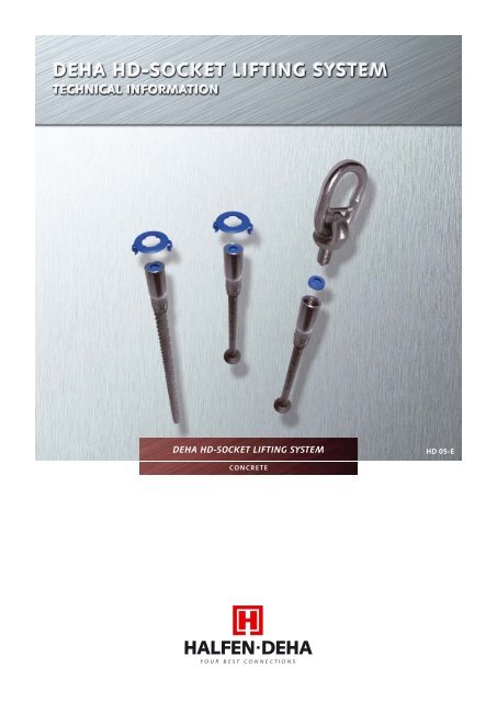
<strong>DEHA</strong> <strong>HD</strong>-<strong>SOCKET</strong> <strong>LIFTING</strong> <strong>SYSTEM</strong><strong>HD</strong> 05-ECONCRETE
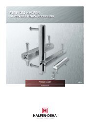
THE <strong>HD</strong>-<strong>SOCKET</strong> <strong>LIFTING</strong> <strong>SYSTEM</strong>Greater safety, fewer components,integral socket protectorSocket protector system with dataclipThe new generation <strong>HD</strong>-Lifting Systemwith socket protector and integral dataclip caters for the load range up to 15tonnes with only eight load groups.In practice, this means:The new generation <strong>HD</strong>-Lifting Anchorhas been designed with an integralsocket protector. This is cleary labelledwith the load group (data clip).Fit the data clip supplied with the unit.• fewer components,• less storage space,• Iower stocking requirements,• less care and maintenance oflifting linkThe dimensions of the new <strong>HD</strong>-LiftingAnchors are carefully designed to keepdiameter to a minimum, which makesthem particulary suitable for use withthin-walled precast elements.Wider application due to smallerdimensionsThe compact design the <strong>HD</strong>-Combi-Anchor, with its optimum lengthand foot shape, offers a wide range ofbenefits:• Less space required in theprecast element• Smaller structural componentdimensions• Easy installation in the formworkand reinforcement• Short anchors• Low weightThis patented system offers protectionagainst contamination from laitanceand dirt, and the ingress of water. Thisprevents ice or water from accumulatingin the anchor socket, and significantlyreduces the risk of damage from corrosion.The integration of a colour-codeddata clip, specifying the manufacturer,thread size and load group, satisfies theidentification requirements according toZH 1/17, for increased safety.Robust lifting link for increased safetyand economyThe robust <strong>HD</strong>-Lifting Link, with itsfixed steel link, provides a high level ofsafety and offers clear economic benefitsdue to the increased service life. The<strong>HD</strong>-Lifting Link has the following outstandingfeatures:• A loop ready for the crane hookwhich is permanently marked withits identification and resistant towear.• A robust ring-bolt with rolled andspecially hardened thread.Screw the nailing plate into the data clip to drivethe HSS protector down the socket. Rotate the dataclip in the desired direction (depending on theposition of the angled lift reinforcement).Ready for casting in. Fix the nailing plate to theformwork and wire the tail to the reinforcement ifnecessary.The <strong>HD</strong>-Lifting Link is easy to use,withstands diagonal and shear forcesand activates the socket protector. Thehexagonal driver makes it easy to bothscrew down the thread protector forlifting and bring it up again when liftingis complete.<strong>HD</strong> load groupsRd 12 Rd 16 Rd 20 Rd 24 Rd 30 Rd 36 Rd 42 Rd 521.3 2.5 4.0 5.0 7.5 10.0 12.5 15.00.5 0.8 1.2 1.6 2.0 2.5 4.0 6.3 8.0 12.5 15.0Rd12 Rd 14 Rd 16 Rd 18 Rd 20 Rd 24 Rd 30 Rd 36 Rd 42 Rd 52 Rd 56traditional load groups2
CONTENTS<strong>SYSTEM</strong>-OVERVIEW 4<strong>HD</strong>-Socket Anchors 4Corrosion Protection 4<strong>HD</strong>-Lifting Attachments 5Accessories 5THE RANGE 6<strong>HD</strong>-Socket Anchors 6<strong>HD</strong>-Lifting Attachments 7Accessories 7<strong>SA</strong>FETY 8Safety regulations according to ZH 1/17 8Labelling 8Safety factors 8Installation and application 8Quality control 8CRITERIA FOR SELECTING THE <strong>HD</strong>-<strong>SOCKET</strong> <strong>LIFTING</strong> <strong>SYSTEM</strong> 9Use of the lifting anchor 9Criteria for choice of anchor 9Weight of precast element 9Number of anchors 9Positioning of anchors 9Static systems 9Angle of lift 10Dynamic forces 10Adhesion to the mould 10Tensile forces to the anchor 11Load angle, edge distance and spacings 11Corrosion protection 11Fire protection 11<strong>HD</strong>-<strong>SOCKET</strong> <strong>LIFTING</strong> <strong>SYSTEM</strong>S 12Allowable load capacity, dimensions and reinforcement for <strong>HD</strong>-Anchors 12Allowable load capacity, dimensions and reinforcement for <strong>HD</strong>-Rod Anchors 14Allowable load capacity, dimensions and reinforcement for <strong>HD</strong>-Short Anchors 16Allowable load capacity, dimensions and reinforcement for <strong>HD</strong>-Plate Anchors 17Allowable load capacity, dimensions and reinforcement for <strong>HD</strong>-Plain Anchors With Hole 18<strong>HD</strong>-<strong>LIFTING</strong> ATTACHMENTS 19General information 19<strong>HD</strong>-Lifting Link 19<strong>HD</strong>-Perfect Lifting Head 20<strong>HD</strong>-Adaptor 20ACCESSORIES 21<strong>HD</strong>-Nailing Plate, plastic 21<strong>HD</strong>-Nailing Plate, steel 21<strong>HD</strong>-Magnetic Plate 21<strong>HD</strong>-Sealing Plate 21ASSEMBLY AND INSTALLATION OF THE <strong>HD</strong>-<strong>LIFTING</strong> ANCHOR 22<strong>HD</strong>-Anchors 22Installation of the <strong>HD</strong>-Lifting Anchor 22<strong>LIFTING</strong> AND TRANSPORT 23Handling the lifting attachments 233
<strong>SYSTEM</strong> – OVERVIEW<strong>HD</strong>-<strong>SOCKET</strong> <strong>LIFTING</strong> <strong>SYSTEM</strong><strong>HD</strong>-<strong>SOCKET</strong> ANCHORS<strong>HD</strong>-AnchorDesignation 6360-Load group<strong>HD</strong>-Rod AnchorDesignation 6361-Load group<strong>HD</strong>-Short AnchorDesignation 6360-Load groupFor lifting a wide range of different sizedprecast concrete elements.Load groups 1.3 - 15.0. Available:• Galvanized Socket, carbon steel rod• Dacromet socket, carbon steel rod• Stainless steel socket,carbon steel rodsee Pages 12/13For use with especially thin precastconcrete elements such as the walls ofgarages and transformer stations.Load groups 1.3 - 15.0. Available:• Galvanized Socket, carbon steel rod• Dacromet socket, carbon steel rod• Stainless steel socket,carbon steel rodsee Pages 14/15For lifting thin structural elements suchas floor slabs etc.Load groups 1.3 - 5.0. Available:• Galvanized Socket, carbon steel rod• Dacromet socket, carbon steel rod• Stainless steel socket,carbon steel rodsee Page 16<strong>HD</strong>-Plate AnchorDesignation 6370-Load group<strong>HD</strong>-Plain Anchor With HoleDesignation 6376-Load groupFor lifting large, thin precast elementssuch as slabs or demolding panels.Load groups 1.3 - 7.5. Available:• Galvanized• Dacromet• Stainless steelsee Page 17For lifting thin precast walls or for usewith low-strength concrete. Reinforcementtail essential.Load groups 1.3 - 10.0.Available:• Galvanized• Dacromet• Stainless steelsee Page 18CORROSION PROTECTION – CARBON STEEL“DACROMET” is a metallic coating(8 - 10 μm) which mainly consists of zincand aluminium flakes. These are blendedwith a mineral chromium oxide binder.The overlapping zinc and aluminiumflakes and the ceramic binder form anexcellent barrier against external effects.The zinc corrodes in preference to thesteel and protects the steel and internalthread of the socket.The cathodic protection ensures optimumcorrosion protection, particularlywhen exposed to the weather.Advantages for the customer• Better thread protection.• Significantly increased corrosionprotection in comparison to electroplatedzinc.• No risk of hydrogen embrittlement.• Better resistance to obrasion thanelectroplated zinc.• High resistance to operating materialssuch as solvents and oils etc.• The dacrometisation process is listedin all the important national andinternational standards.• DIN EN ISO 10683 non-electrolyticallyapplied zinc-flake coatings.4
<strong>SYSTEM</strong> – OVERVIEW<strong>HD</strong>-<strong>SOCKET</strong> <strong>LIFTING</strong> <strong>SYSTEM</strong><strong>HD</strong>-<strong>LIFTING</strong> ATTACHMENTS<strong>HD</strong>-Lifting LinkDesignation 6362-Load group<strong>HD</strong>-Perfect Lifting HeadDesignation 6377-Load group<strong>HD</strong>-AdaptorDesignation 6366-Load groupFor lifting precast elements inconjunction with <strong>HD</strong>-Socket Anchors.Load groups 1.3 - 15.0see Page 19For lifting precast elements incombination with <strong>HD</strong>-Socket Anchors.Load groups 1.3 - 15.0see Page 20The <strong>HD</strong>-Adaptor enables the universallifting head clutch to be used with the<strong>HD</strong>-Socket Lifting Anchor. The <strong>DEHA</strong>Universal Head Lifting Clutch (6102) isengaged in the adaptor for lifting. Loadgroups 1.3 - 15.0see Page 20ACCESSORIES<strong>HD</strong>-Nailing Plate, plasticDesignation 6364-Load group<strong>HD</strong>-Nailing Plate, steelDesignation 6369-Load group<strong>HD</strong>-Magnetic PlateDesignation 6365-Load groupFor attaching the <strong>HD</strong>-Socket LiftingAnchor to the mould.For thread sizes M/Rd 12-52.see Page 21For attaching the <strong>HD</strong>-Socket LiftingAnchor to the mould.For thread sizes M/Rd 12-52.see Page 21For attaching the <strong>HD</strong>-Socket LiftingAnchor to the mould.For thread sizes M/Rd 12-52.see Page 21<strong>HD</strong>-Sealing PlateDesignation 6513-Load groupFor sealing the <strong>HD</strong>-Socket LiftingAnchor as protection against contaminationand for use in face concrete.For thread sizes M/Rd 12-24.see Page 215
THE RANGE<strong>HD</strong>-<strong>SOCKET</strong> <strong>LIFTING</strong> <strong>SYSTEM</strong><strong>HD</strong>-<strong>SOCKET</strong> ANCHORS<strong>HD</strong>-Anchor <strong>HD</strong>-Rod Anchor <strong>HD</strong>-Short AnchorLoad groupLoad groupLoad groupDesignationOrder numberDesignationOrder numberDesignationOrder numberSocket electroplatedgalvavized1.3 6360-1.3-130 0740.130-000012.5 6360-2.5-200 0740.130-000024.0 6360-4.0-258 0740.130-000035.0 6360-5.0-325 0740.130-000047.5 6360-7.5-400 0740.130-0000510.0 6360-10.0-475 0740.130-0000612.5 6360-12.5-550 0740.130-0000715.0 6360-15.0-575 0740.130-00008Socket electroplatedgalvavized1.3 6361-1.3-300 0740.140-000012.5 6361-2.5-400 0740.140-000024.0 6361-4.0-480 0740.140-000035.0 6361-5.0-540 0740.140-000047.5 6361-7.5-700 0740.140-0000510.0 6361-10.0-800 0740.140-0000612.5 6361-12.5-920 0740.140-0000715.0 6361-15.0-1100 0740.140-00008Socket electroplatedgalvavizedSocket stainlesssteel A41.3 6360-1.3-070 0740.130-000172.5 6360-2.5-090 0740.130-000184.0 6360-4.0-125 0740.130-000195.0 6360-5.0-140 0740.130-000201.3 6360-1.3-070 A4 0740.130-000212.5 6360-2.5-090 A4 0740.130-000224.0 6360-4.0-125 A4 0740.130-000235.0 6360-5.0-140 A4 0740.130-00024Socket stainless steel A41.3 6360-1.3-130 A4 0740.130-000092.5 6360-2.5-200 A4 0740.130-000104.0 6360-4.0-258 A4 0740.130-000115.0 6360-5.0-325 A4 0740.130-000127.5 6360-7.5-400 A4 0740.130-0001310.0 6360-10.0-475 A4 0740.130-0001412.5 6360-12.5-550 A4 0740.130-0001515.0 6360-15.0-575 A4 0740.130-00016Socket stainless steel A41.3 6361-1.3-300 A4 0740.140-000092.5 6361-2.5-400 A4 0740.140-000104.0 6361-4.0-480 A4 0740.140-000115.0 6361-5.0-540 A4 0740.140-000127.5 6361-7.5-700 A4 0740.140-0001310.0 6361-10.0-800 A4 0740.140-0001412.5 6361-12.5-920 A4 0740.140-0001515.0 6361-15.0-1100 A4 0740.140-00016Socketdacrometised1.3 6360-1.3-070 DC 0740.130-000332.5 6360-2.5-090 DC 0740.130-000344.0 6360-4.0-125 DC 0740.130-000355.0 6360-5.0-140 DC 0740.130-000361.3 6360-1.3-130 DC 0740.130-000251.3 6361-1.3-300 DC 0740.140-00017Socket dacrometised2.5 6360-2.5-200 DC 0740.130-000264.0 6360-4.0-258 DC 0740.130-000275.0 6360-5.0-325 DC 0740.130-000287.5 6360-7.5-400 DC 0740.130-0002910.0 6360-10.0-475 DC 0740.130-0003012.5 6360-12.5-550 DC 0740.130-00031Socket dacrometised2.5 6361-2.5-400 DC 0740.140-000184.0 6361-4.0-480 DC 0740.140-000195.0 6361-5.0-540 DC 0740.140-000207.5 6361-7.5-700 DC 0740.140-0002110.0 6361-10.0-800 DC 0740.140-0002212.5 6361-12.5-920 DC 0740.140-0002315.0 6360-15.0-575 DC 0740.130-0003215.0 6361-15.0-1100 DC 0740.140-00024Load group<strong>HD</strong>-PlateAnchorLoad group<strong>HD</strong>-PlainAnchorWith HoleElectroplatedgalvavized6Stainless steel A4DacrometisedDesignation Order number1.3 6370-1.3 0740.180-000012.5 6370-2.5 0740.180-000024.0 6370-4.0 0740.180-000035.0 6370-5.0 0740.180-000047.5 6370-7.5 0740.180-000051.3 6370-1.3 A4 0740.180-000062.5 6370-2.5 A4 0740.180-000074.0 6370-4.0 A4 0740.180-000085.0 6370-5.0 A4 0740.180-000097.5 6370-7.5 A4 0740.180-000101.3 6370-1.3 DC 0740.180-000112.5 6370-2.5 DC 0740.180-000124.0 6370-4.0 DC 0740.180-000135.0 6370-5.0 DC 0740.180-000147.5 6370-7.5 DC 0740.180-00015ElectroplatedgalvavizedStainless steel A4DacrometisedDesignation Order number1.3 6376-1.3 0740.190-000012.5 6376-2.5 0740.190-000024.0 6376-4.0 0740.190-000035.0 6376-5.0 0740.190-000047.5 6376-7.5 0740.190-0000510.0 6376-10.0 0740.190-000061.3 6376-1.3 A4 0740.190-000072.5 6376-2.5 A4 0740.190-000084.0 6376-4.0 A4 0740.190-000095.0 6376-5.0 A4 0740.190-000107.5 6376-7.5 A4 0740.190-0001110.0 6376-10.0 A4 0740.190-000121.3 6376-1.3 DC 0740.190-000132.5 6376-2.5 DC 0740.190-000144.0 6376-4.0 DC 0740.190-000155.0 6376-5.0 DC 0740.190-000167.5 6376-7.5 DC 0740.190-0001710.0 6376-10.0 DC 0740.190-00018
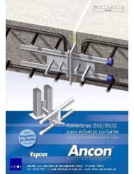
<strong>SA</strong>FETY<strong>SA</strong>FETY REGULATIONS OF THE MAIN GERMAN INDUSTRIAL EMPLOYERS’ LIABILITY INSURANCEASSOCIATION FOR <strong>LIFTING</strong> ANCHORS AND <strong>LIFTING</strong> ANCHOR <strong>SYSTEM</strong>S FOR PRECAST CONCRETEELEMENTS ZH 1/17These safety regulations apply toseries manufactured lifting anchors andlifting anchor systems for transportingprecast concrete elements with liftingequipment. Under these regulations,lifting anchor systems are defined as assemblagesconsisting of the componentwhich is permanently anchored in theprecast concrete element (lifting anchor)and the load-bearing component whichis temporarily attached for lifting purposes.Lifting anchors and lifting anchorsystems must be manufactured in sucha way that, when used properly, theyensure that the precast element is liftedsafely.Load lifting deviceAngle of liftβSuspension deviceLifting tackleLifting attachmentLoadLiftinganchor<strong>HD</strong>-Lifting SystemLABELLINGINSTALLATION AND APPLICATIONAll <strong>HD</strong>-Lifting Anchors and lifting attachmentsare clearly marked for thebenefit of the user. According to thesafety regulations for lifting anchor systems,the identification markings mustalso be clearly visible after installation.This requirement is fulfilled by the preassembledsocket protector systemwhich is clearly marked.<strong>SA</strong>FETY FACTORSThe components in the <strong>HD</strong>-LiftingAnchor System is designed with a safetyfactor of at least 3 against steel failure.The load limits given in the tables havea safety factor of at least 2.5 againstconcrete failure. Note, however thatall loads must be factored as shown onpage 9.The <strong>HD</strong>-Socket Lifting System must onlybe installed in accordance with the followingtechnical instructions.Combining components of the systemwith those of other manufacturers isnot permitted. Re-using lifting anchorsis not permitted. Repeated lifting whenlifting and installing the precast elementis not considered as re-use. For liftinganchors which are intended for longterm use, such as crane ballast kentledgeand cover slabs, the sockets mustbe manufactured from stainless steel, inaccordance with the approval certificatefor “Stainless steels”, Approval No.Z- 30.3-6. Incorrectly installed liftinganchors, or lifting anchors which havedamaged components, such as corrosionor visible deformation, must not be usedfor lifting purposes.The Installation instructions for the differentsystems must be available at thepoint where the anchor system is beingused, i.e. at the precast yard and on theconstruction site. Production managementand site management must ensurethat personnel are aware of and haveunderstood the installation and generalsafety regulations.QUALITY CONTROLAll required testing of lifting anchorsand lifting attachments is carried outas part of the internal qualityassurance system operated byHALFEN-<strong>DEHA</strong> which complieswith DIN ISO 9001/2000.8
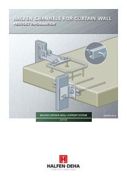
CRITERIA FOR SELECTING THE <strong>HD</strong>-<strong>SOCKET</strong> <strong>LIFTING</strong> <strong>SYSTEM</strong>ANGLE OF LIFTDYNAMIC FORCE<strong>SA</strong>DHESION TO THE MOULDWhen a triangular lifting sling is used,the forces acting on the anchors (slingloads) are greater than those of simplediagonal shear. The loading on the anchorsand ropes increases with the angleof lift.When selecting the anchor, this effectis taken into account by the factor inrelation to the spread angle.We recommend a spread angleof 60°(Table 1). Spread angles above 90° arenot permitted.The size of the dynamic loading is determinedby the choice of the liftingtackle between the crane and the liftingattachment.Cables made from steel or syntheticfibre have a damping effect. This effectincreases with increasing cable length.On the other hand, short chains have anadverse effect. The forces acting on thelifting anchor must be calculated takinginto account the shock factor (Table 2).Deviations from the shock factors accordingto Table 2 can vary significantlyaccording to the situation and givenconditions. If necessary, the values accordingto DIN 15 018 must be used.When the precast element is first liftedout of the mould, the force requiredmay be many times more than the actualweight of the concrete. This is dueto the suction, adhesion and frictionbetween the mould and the concreteelement. These effects can be reducedby using a suitable release agent onthe mould. The adhesion to the mouldis determined by factors such as themould surface.Table 3 Adhesion forceType of mouldAdhesion force h asmooth oiled mould 1 kN/m 2smooth non-oiledmould2 kN/m 2rough mould 3 kN/m 2Table 2 Shock factorsTable 1 Spread angleAngle Spread angle factor 0° 1lifting equipmentStationary crane,revolving crane, railmountedcraneStationary crane,revolving crane, railmountedcraneLiftingspeed m/min.Shockfactor< 90 1.0 - 1.1≥ 90 ≥ 1.3Unless special steps have been taken torelease the precast element, this adhesionshould be taken into account usingthe adhesion factor shown in Table 4when choosing the anchor, particularlywith double π slabs and waffle slabs.Table 4 Adhesion factor30° 1.0460° 1.16Lifting and transporton level ground– ≥ 1.65Type of slabAdhesion factor slabs ≥ 290° 1.41> 90° not permittedLifting and transporton level ground– ≥ 2.0Ribbed slabs ≥ 3Waffle slabs ≥ 510
CRITERIA FOR SELECTING THE <strong>HD</strong>-<strong>SOCKET</strong> <strong>LIFTING</strong> <strong>SYSTEM</strong>TENSILE FORCES ON THEANCHORThe tensile force Z acting on the anchoris normally determined by the followingequation:Lifting from the mouldZ = G x x / norZ = (G + ha x A) x / nLifting load caseZ = G x x / nwhere:Z = tensile force on anchor (kN)G = weight of precast concreteunit (kN)Ha = adhesion force (kN/m 2 )A = base area (m 2 )n = number of load-carrying anchorsco = spread angle factor = shock factor = adhesion factorDiagonal pull angle 12,5° to 45°a ra aa rThe transverse pull can be omittedwhen using a tilting table and a loadangle of
<strong>HD</strong>-<strong>SOCKET</strong> <strong>LIFTING</strong> <strong>SYSTEM</strong><strong>HD</strong>-ANCHORALLOWABLE LOAD CAPACITY, DIMENSIONS AND REINFORCEMENT FOR <strong>HD</strong>-ANCHORSFor lifting a wide range of sizes of precastconcrete elements. Load groups1.3 - 15.0. Also available with stainlesssteel sockets.Table 5 Allowable load capacities for <strong>HD</strong>-Anchors in kNLoad group1.32.54.05.07.510.012.515.0Minimum elementthicknessb (mm)Axial load andangled loadup to 30° [ß]Concrete compressive strength 15 N/mm 2 Concrete compressive strength 25 N/mm 2Angled loadup to 45° [ß]Pitching loadAxial load andangled loadup to 30° [ß]Angled loadup to 45° [ß]Pitching load80 13.0 10.4 5.9 13.0 10.5 7.5100 13.0 10.5 7.5 13.0 10.5 7.5120 13.0 10.5 7.5 13.0 10.5 7.580 18.7 15.0 4.2 24.1 18.9 5.4100 22.7 18.2 6.8 25.0 18.9 8.8120 25.0 18.9 9.9 25.0 18.9 12.780 24.0 21.6 4.1 31.0 27.9 5.3100 29.8 26.9 6.9 38.5 31.8 8.9120 33.1 29.8 8.9 40.0 31.8 11.5140 36.0 31.8 12.9 40.0 31.8 16.6160 39.0 31.8 17.5 40.0 31.8 22.5100 33.4 33.4 9.3 43.1 42.1 12.0120 40.0 40.0 13.1 50.0 42.1 16.9140 45.6 42.1 14.7 50.0 42.1 19.0160 49.0 42.1 20.0 50.0 42.1 25.8140 56.0 56.0 18.1 72.3 67.7 23.4160 66.8 66.8 24.2 75.0 67.7 31.2180 71.8 67.7 31.1 75.0 67.7 40.1200 75.0 67.7 39.1 75.0 67.7 42.5160 78.7 78.7 24.0 100.0 92.6 30.9180 90.7 90.7 30.5 100.0 92.6 39.4200 98.3 92.6 38.1 100.0 92.6 49.1220 100.0 92.6 46.2 100.0 92.6 57.0180 111.6 111.6 33.2 125.0 120.2 42.8200 125.0 120.2 40.1 125.0 120.2 51.7220 125.0 120.2 48.4 125.0 120.2 62.4240 125.0 120.2 57.9 125.0 120.2 71.0180 114.1 114.1 29.2 147.4 144.8 37.7200 126.8 126.8 36.2 150.0 144.8 46.7220 139.5 139.5 44.3 150.0 144.8 57.2240 150.0 144.8 53.0 150.0 144.8 68.5280 150.0 144.8 72.5 150.0 144.8 85.5Additional reinforcement as shown onpage 9.The value given for the concrete compressivestrength relates to normal concreteaccording to DIN EN 206 or thenew DIN 1045-1 on 150 mm test cubes.The <strong>HD</strong>-Lifting Link is supported againstthe concrete. It is essential that the correctnailing plate is used to provide thecorrect fit.12
<strong>HD</strong>-<strong>SOCKET</strong> <strong>LIFTING</strong> <strong>SYSTEM</strong><strong>HD</strong>-ANCHORTable 6 Dimensions and reinforcement for <strong>HD</strong>-Anchors in mmLoad groupAxial pull<strong>HD</strong>-Anchor dimensionsMinimumelementthicknessbPosition ofanchors *Rd D D 1 D 2 L a r min a a min1.3 12 10 17 25 1302.5 16 14 22 35 2004.0 20 18 27 45 2585.0 24 20 32 50 3257.5 30 24 39 60 40010.0 36 28 47 70 47512.5 42 34 55 85 55015.0 52 34 68 85 575a rbEdgereinforcementAdditional reinforcementAxial load Angled load up to 45° Pitching loadEdge reinforcementd 1 l 1 d B d 2 l 2 ** h 1 *** R 180100 280 560 - 10 600 19 10 6003343120 538037100 420 840 - 10 600 24 12 800 47120 578042100 52120 400 800 - 12 1000 29 14 950 62140 72160 8210056120 66500 1000 - 12 1000 34 16 1000140 76160 8614084160 94615 1230 2Ø12 20 1100 41 20 1200180 104200 11416098180 108730 1460 2Ø14 20 1100 49 20 1200200 118220 128180117200 127845 1690 2Ø14 20 1100 57 25 1500220 137240 147180123200 133220 880 1760 2Ø14 25 1100 70 25 1800 143240 153280 17390° pitching* a r = Edge distance* a a = spacings** Extended length*** at c min = 20 mm1011131620242834Angled pull up to = 45°Q 188Meshreinforcement,bent or similarreinforcement15°d1 dBa rQ 188Meshreinforcement,bent or similarreinforcementl 1bbQ 188Mesh reinforcement,bent or similar reinforcementa rTransversepull – additionThe pitching reinforcement on bothsides also serves as diagonal-pull reinforcement.Additional angled-pullreinforcement is not necessary. Thisadditional reinforcement placed in withtight contact with the socket.Transverse pull – additionl 2R 1R 1≤ 90°d2h1Note:Element thickness, edge distance andspacings are for guidance only. If indoubt please consult HALFEN-<strong>DEHA</strong>.Note: < 45° is preferred.13
<strong>HD</strong>-<strong>SOCKET</strong> <strong>LIFTING</strong> <strong>SYSTEM</strong><strong>HD</strong>-SHORT ANCHORALLOWABLE LOAD CAPACITY, DIMENSIONS AND REINFORCEMENT FOR <strong>HD</strong>-SHORT ANCHORSFor lifting flat structural elements suchas floor slabs etc.Load groups 1.3 - 5.0Also available with dacrometised orstainless steel socket.The values for intermediate slab thicknessescan be interpolated.Table 9 Allowable load capacities for <strong>HD</strong>-Short Anchors in kNLoad groupMinimumstructuralelementthicknessb (mm)Concrete compressive strengthConcrete compressive strength15 N/mm 2 25 N/mm 2 Minimumstructuralelementthicknessb (mm)15 N/mm 2 25 N/mm 2Axial andangled pullup to 45°Axial andangled pullup to 45°Axial andangled pullup to 45°Axial andangled pullup to 45°1.3 115 13.0 13.0 115 13.0 13.02.5 160 19.5 25.0 125 16.5 21.34.0 220 31.2 40.0 160 25.3 32.65.0 275 39.3 50.0 175 29.1 37.5Table 10 Dimensions and reinforcement for the <strong>HD</strong>-Short Anchors in mmLoad groupDimensions of <strong>HD</strong>-Short Anchors Anchor arrangement *Additional reinforcementDiagonal pull up to 45°Rd D D 1 D 2 L a r min a a min d 1 l 1 d B1.3 12 10 17 25 70 250 500 10 370 192.5 16 14 22 35 90 400 800 12 520 244.0 20 18 27 45 125 500 1000 14 610 295.0 24 20 32 50 140 650 1300 14 720 34Axial pull* a r = Edge distance (a r min applies to axial pull.For angled pull, see reinforcement)* a a = interaxial distancea rAngled pull up to = 45°a r bQ 188Mesh reinforcement,bent or similar qualitysteel reinforcement rodThe required additional reinforcementmust be read from the reinforcementdrawings and tables for the correspondingload groups. The value givenfor the concrete compressive strengthrelates to normal concrete according toDIN EN 206 or the new DIN 1045-1 on150 mm test cubes.10°bdBd1l 1Diagonal pull stirrupQ 188Mesh reinforcement,bent or similar qualitysteel reinforcement rod16
<strong>HD</strong>-<strong>SOCKET</strong> <strong>LIFTING</strong> <strong>SYSTEM</strong><strong>HD</strong>-PLATE ANCHORALLOWABLE LOAD CAPACITY, DIMENSIONS AND REINFORCEMENT FOR <strong>HD</strong>-PLATE ANCHORS<strong>HD</strong>-Plate Anchors are designed for liftinglarge, thin-walled precast concrete elementswhich should be lifted perpendicularto their main dimension (slabs andThe slab must be dimensioned for thetransport load case and correspondingtensile bending reinforcement via theanchors.Table 11 Permitted load-carrying capacities for <strong>HD</strong>-Plate Anchors in kNMinimum elementConcrete compressive strength 15N/mm 2Load groupthicknessb (mm)Axial load Angled pull up to 45°1.3 100 13.0 13.02.5 115 25.0 25.04.0 150 40.0 40.05.0 160 50.0 50.07.5 200 75.0 75.0Table 12 Dimensions and reinforcement for <strong>HD</strong>-Plate Anchors in mmMinimum AnchorAdditional reinforcementDimensions of <strong>HD</strong>-Plate AnchorselementLoad grouparrangement * Axial pull and diagonal pull Diagonal pull up to 45°thicknessRd L D t a b b a r min a a min d s l 2 l 3 h d 1 l 1 d B1.3 12 46 17 4 50 50 100 250 500 4 x 8 60 425 40 10 370 192.5 16 54 22 5 60 80 115 400 800 4 x 10 90 640 50 12 520 244.0 20 72 27 6 80 100 150 500 1000 4 x 12 110 830 55 14 610 295.0 24 84 32 6 100 130 160 650 1300 4 x 14 140 1140 60 14 720 347.5 30 98 39 8 130 130 200 650 1300 4 x 16 140 1250 60 16 870 41Axial pull* a r = Edge distance* a a = Interaxial distancea rb10°Angled pull up to = 45°d1 dBha r Diagonal pull stirrupl 1l 330°l 2dsQ 188Mesh reinforcement,bent or similar qualitysteel reinforcement rodbThe additional reinforcement is laid overthe footplate of the <strong>HD</strong>-Plate Anchorand fixed. The concrete reinforcingsteels used in the suspension reinforcementmust be arranged on the footplatein two layers at right-angles to eachother with the smallest distance possibleto the threaded socket with pressurecontact with the lower layers runningparallel to the shorter side of the footplate.The angled pull reinforcementmust be installed against the socket andwith a maximum inclination of 12.5°,if provided with end hooks, the leglengths in Table 12 apply.The slab thickness must not exceed 25cm for angled lift because of the bondstress which is applied. (The minimumslab thicknesses and minimum reinforcementsare shown in the tables.)17
<strong>HD</strong>-<strong>SOCKET</strong> <strong>LIFTING</strong> <strong>SYSTEM</strong><strong>HD</strong>-PLAIN ANCHOR WITH HOLEALLOWABLE LOAD CAPACITY, DIMENSIONS AND REINFORCEMENT FOR <strong>HD</strong>-PLAIN ANCHORS WITH HOLEThe <strong>HD</strong>-Plain Anchor With Hole areused for lifting thin precast walls orused in low-strength concrete.The permissible interaxial distance ofthe lifting anchor sockets is 2 x minimumedge distance. The necessaryreinforcement rod must be introducedthrough the hole in the lower part ofthe <strong>HD</strong>-Plain Anchor With Hole.Table 13 Permitted load-carrying capacities for <strong>HD</strong>-Plain Anchor With Hole in kNMinimum elementConcrete compressive strength 15N/mm 2Load groupthicknessb (mm)Axial load Diagonal pull up to 45°1.3 80 13.0 10.52.5 100 25.0 20.04.0 110 40.0 32.05.0 120 50.0 40.07.5 130 75.0 60.010.0 140 100.0 80.0Load groupLoad groupTable 14 Dimensions and reinforcement for <strong>HD</strong>-Plain Anchor With Hole in mmMinimum AnchorAdditional reinforcementDimensions for <strong>HD</strong>-Plain Anchor With Hole elementLoad grouparrangement *Axial pull Angled pull up to 45°thicknessRd L D t a b a r min a a min d s l ** d br d 1 l 1 d B1.3 12 65 21 13.5 12 80 250 500 10 650 40 8 250 192.5 16 70 28 17.0 16 100 300 600 12 1000 48 10 320 244.0 20 85 38 24.5 21 110 350 700 16 1200 64 12 420 295.0 24 93 40 25.5 22 120 375 750 16 1500 64 14 520 347.5 30 116 46 28.0 28 130 500 1000 20 1750 80 16 600 4110.0 36 136 51 30.0 30 140 600 1200 25 1850 25 20 750 49Axial pulla rAngled pull up to = 45°a r15°bb* a r = Edge distance* a a = Interaxial distance** Extended lengthQ 188Mesh reinforcement,bent or similar qualitysteel reinforcement rod60°d brThe <strong>HD</strong>-Plain Anchor With Hole isdesigned so that the entire anchor forceis transferred into the concrete via thereinforcement tail. The tail is not suppliedby HALFEN-<strong>DEHA</strong>.d sIt must be inserted so that it fits firmlyin the lower edge of the hole. The necessaryadditional reinforcement mustbe read from the reinforcement drawingsand tables for the correspondingload groups. The value given for theconcrete compressive strength relates tonormal concrete according to DIN EN206 or the new DIN 1045-1 on 150 mmtest cubes.The additional reinforcement for angledlift must be placed light against thesocket.d1 dBl 118
<strong>HD</strong>-<strong>LIFTING</strong> ATTACHMENTSGENERAL INFORMATIONThe lifting attachments must be screwedin fully. Only one thread turn must bevisible outside the lifting anchor. If socketthreads which are contaminated withconcrete residues must be cleaned. If indoubt please contact HALFEN-<strong>DEHA</strong>.Lifting attachments with loops mustbe suspended in loading hooks withlarge return radii. Sharp edged hooks orhooks with a cross section which is toosmall can cause excessive wear due tothe small bending radii. This will lead toan early need for replacement.The accident prevention regulationsmust be followed at all times.VBG 9 “Crane” and VBG 9a “Loadsuspensiondevices for lifting” must befollowed in particular.<strong>HD</strong>-Lifting Attachments are labelled toshow the name of the manufacturer, theyear of manufacture (e.g. 04), the thread(e.g. Rd 30) and the load group.<strong>HD</strong>-<strong>LIFTING</strong> LINKThe <strong>HD</strong>-Lifting Link is made speciallyfor use with the <strong>HD</strong>-Anchors. The<strong>HD</strong>-Perfect Lifting Head may also beused (see page 20).The <strong>HD</strong>-Lifting Link can activate theintegrated socket protector, by meansof the hexagon on the stud, and screwinto the socket. After casting the <strong>HD</strong>-Anchor, the socket protector is at theupper edge of the socket and thereforehelps to prevent the socket from beingcontaminated.For angled lift are pitching, the eyeboltof the <strong>HD</strong>-Lifting Link supports againstthe concrete provided the anchorhas been installed by means of the<strong>HD</strong>-Nailing Plate or <strong>HD</strong>-Magnetic Plate.The dimensions and load-capacities ofthe <strong>HD</strong>-Lifting Link shown in the tablebelow.Table 15 Dimensions of the <strong>HD</strong>-Lifting LinkDesignationOrdernumber0742.130-Load group/load capacityRdWeightkg6362-1.3 00001 1.3 12 0.57 179.5 150 29.5 76 50 136362-2.5 00002 2.5 16 0.65 179.5 150 29.5 76 50 136362-4.0 00003 4.0 20 1.21 197.0 162 35.0 82 50 166362-5.0 00004 5.0 24 1.29 197.0 162 35.0 82 50 166362-7.5 00005 7.5 30 2.40 228.0 177 51.0 94 50 226362-10.0 00006 10.0 36 2.54 236.5 177 59.5 94 50 226362-12.5 00007 12.5 42 4.84 298.5 218 67.5 117 65 266362-15.0 00008 15.0 52 5.31 298.5 218 80.5 117 65 26L totalmmLmmcmmBmmbmmdmm19
<strong>HD</strong>-<strong>LIFTING</strong> ATTACHMENTS<strong>HD</strong>-PERFECT <strong>LIFTING</strong> HEADThe <strong>HD</strong>-Perfect Lifting Head is particularlysuitable for angled pull andpitching. The application instructions forthe <strong>HD</strong>-Lifting Link must be followed.Table 15 Dimensions of the <strong>HD</strong>-Perfect Lifting HeadDesignationOrder number0742.130-Load group Rd L6377-1.3 00001 1.3 12 3006377-2.5 00002 2.5 16 3906377-4.0 00003 4.0 20 5106377-5.0 00004 5.0 24 5506377-7.5 00005 7.5 30 7006377-10.0 00006 10.0 36 7606377-12.5 00007 12.5 42 8606377-15.0 00008 15.0 52 940<strong>HD</strong>-ADAPTORThe <strong>HD</strong>-Adaptor enables the pin-liftingsystem to be used with the <strong>HD</strong>-SocketSystem. The universal head lifting clutchfor the appropriate load group is linkedinto the adaptor.DesignationOrdernumber0742.130-LoadgroupRdDmmD 1mmD 2mmHmmFits universal head lifting clutchDesignationOrder number0738.010-Load group6366-1.3 00001 1.3 12 70 40 30 10 6102-1.3 00001 1.36366-2.5 00002 2.5 16 78 40 30 10 6102-1.5/2.5 00002 2 and 2.56366-4.0 00003 4.0 20 97 55 45 10 6102-3/5 00003 4 and 56366-5.0 00004 5.0 24 97 55 45 10 6102-3/5 00003 4 and 56366-7.5 00005 7.5 30 117 70 60 10 6102-6/10 00004 7.5 and 106366-10.0 00006 10.0 36 117 70 60 10 6102-6/10 00004 7.5 and 106366-12.5 00007 12.5 42 177 95 85 12 6102-12/20 00005 15 and 206366-15.0 00008 15.0 52 177 95 85 12 6102-12/20 00005 15 and 2020
<strong>HD</strong>-<strong>SOCKET</strong> <strong>LIFTING</strong> <strong>SYSTEM</strong>ACCESSORIESFIXINGAll <strong>HD</strong>-Anchors must be fixed to the formwork with one of these nailing plates.When the nailing plate is used a recess is produced which accurately conforms to all <strong>HD</strong>-Lifting Attachment.<strong>HD</strong>-NAILING PLATE, PLASTIC<strong>HD</strong>-NAILING PLATE, STEEL<strong>HD</strong>-MAGNETIC PLATE<strong>HD</strong>-Nailing Plates are used to attach<strong>HD</strong>-Socket Anchors to the mould.Plastic nailing plates are available forthread sizes Rd 12 to Rd 52 and are colouredaccording to the thread size.Steel nailing plates available for threadsizes Rd 12 to Rd 52 and are plated.Pattern: zinc electroplate<strong>HD</strong>-Magnetic Plates used to attach <strong>HD</strong>-Socket Anchors to the mould. They areavailable for thread sizes Rd 12 to Rd 52and are plated.Pattern: zinc electroplateTable 18 Dimensions of the <strong>HD</strong>-Plastic Plate Table 19 Dimensions of the <strong>HD</strong>-Steel Plate Table 20 Dimensions of the <strong>HD</strong>-Magnetic PlateLoadgroup Designation DmmHmm1.3 6364-1.3 40 10 000012.5 6364-2.5 40 10 000024.0 6364-4.0 55 10 000035.0 6364-5.0 55 10 000047.5 6364-7.5 70 10 0000510.0 6364-10.0 70 10 0000612.5 6364-12.5 95 12 0000715.0 6364-15.0 95 12 00008Ordernumber0741.160-Loadgroup Designation DOrderHmm mm M number0741.190-1.3 6369-1.3 40 10 6 000012.5 6369-2.5 40 10 10 000024.0 6369-4.0 55 10 12 000035.0 6369-5.0 55 10 12 000047.5 6369-7.5 70 10 12 0000510.0 6369-10.0 70 10 16 0000612.5 6369-12.5 95 12 16 0000715.0 6369-15.0 95 12 16 00008OrderLoadgroup Designation D Hmm mm SW number0741.180-1.3 6365-1.3 40 12 6 000012.5 6365-2.5 40 12 6 000024.0 6365-4.0 55 12 10 000035.0 6365-5.0 55 12 10 000047.5 6365-7.5 70 12 16 0000510.0 6365-10.0 70 12 16 0000612.5 6365-12.5 95 12 16 0000715.0 6365-15.0 95 12 16 00008<strong>HD</strong>-SEALING PLATEThe grey <strong>HD</strong>-Sealing Plate is used forsealing the <strong>HD</strong>-Socket Anchor and isavailable for thread sizes Rd 12, Rd 16,Rd 20 and Rd 24.Table 21 Dimensions of the <strong>HD</strong>-Sealing PlateLoadgroup Designation DmmHmmOrdernumber0741.280-1.3 6513-1.3 40 10 000012.5 6513-2.5 40 10 000024.0 6513-4.0 55 10 000035.0 6513-5.0 55 10 0000421
ASSEMBLY AND INSTALLATION OF THE <strong>HD</strong>-<strong>LIFTING</strong> ANCHOR<strong>HD</strong>-ANCHORSThe <strong>HD</strong>-Anchor is supplied completewith the Socket Protector System.Data Clip<strong>HD</strong>-Anchor<strong>HD</strong>-Plain Anchor With HoleSocket ProtectorThe <strong>HD</strong>-Anchor together with the<strong>HD</strong>-Lifting Link complete the lifting anchorsystem.<strong>HD</strong>-Rod Anchor<strong>HD</strong>-Plate Anchor<strong>HD</strong>-Short AnchorINSTALLING THE <strong>HD</strong>-<strong>LIFTING</strong> ANCHOR <strong>SYSTEM</strong>The <strong>HD</strong>-Nailing Plate is used to attachthe <strong>HD</strong>-Anchor to the mould. It is colour-codedaccording to the load groupand is available in plastic or steel forload groups 1.3 to 15.0.see picture 03The Socket Protector System is screwedinto the threaded sleeve by turning the<strong>HD</strong>-Anchor. There must be no air gapbetween the nailing plate and the anchorsocket. The data clip, which is now clamped,must be moved to the correct positionby rotating it (depending on the positionof the angled pull reinforcement).picture 01Shown:Load group 5.0colour-code blue(see table)picture 02Table 22 Colour codesLoad groupColour code1.3 red2.5 dark grey4.0 dark green5.0 blue7.5 pale grey10.0 orange12.5 yellow15.0 deep blacksee picture 01The Nailing Plates are either nailed tothe mould or screwed in place usingretaining screws through a hole in themould. For steel-formwork, the <strong>HD</strong>-Magnetic Plate, which is attached to themould by an integral magnet may beused.see picture 02Before assembling the <strong>HD</strong>-Anchor, thedata clip must be placed on the threadedstud of the nailing plate. After this,the anchor with the pre-mounted SocketProtector is placed on the hexagonalstud of the nailing plate.The anchor must be fastened to the reinforcementby suitable means so that it doesnot move during concreting. Using forming oilin the area of the nailing plate makes it easierto remove.see picture 04The Nailing Plate can be removed afterthe concrete has hardened. While doingso, it must be ensured that the SocketProtection System is rotated to the sockettop edge.We recommend filling up the hexagonalrecess of the Socket Protector System withgrease or forming oil each time after it isused, particularly during winter. This preventsthe ingress of water in the hexagonal recess,which may freeze and restrict the connectionbetween the threaded stud of the liftinglink and the Socket Protector System. It isadvisable to fill the entire nailing plate recesswith forming oil. This will make it easier toremove any ice which may form.picture 03picture 04 T.E. Sleeve =Top Edge SocketProtector SystemSocketProtectorSystemThe data clip is packed separately. It mustbe used with the appropriate <strong>HD</strong>-Anchor,which has the same identification colour (seepicture 04)22
<strong>LIFTING</strong> AND TRANSPORTHANDLING THE <strong>LIFTING</strong> ATTACHMENTSHandling the lifting attachmentsOnly the <strong>HD</strong>-Lifting Link and the<strong>HD</strong>-Perfect Lifting Head may be used aslifting attachments. The fitting of otherlifting attachments, such as looped cablesis not permitted for safety reasons.OperatingThe <strong>HD</strong>-Lifting Link is a manually- operatedconnection. In general, the accidentprevention regulations must be followedat all times. The VBG 9 „Crane“and VBG 9a „Load-suspension devicesfor lifting“ of the Main German IndustrialEmployer‘s Liability Insurance Associationmust be followed In particular.The recess in the concrete created bythe nailing plate or magnet plate exactlymatches the contour of the <strong>HD</strong>-LiftingAttachment and allows it to be supportedagainst the concrete while theanchor is subjected to diagonal or transversepull.CorrectLabelling<strong>HD</strong>-Lifting Links are marked with thename of the manufacturer, the type andyear of manufacture, the thread andload group.CorrectOptimum load distribution is only possibleif the direction of pull is as shownbelow. If necessary, after screwing the<strong>HD</strong>-Lifting Link fully home, it may beslackened by a maximum of half a turn.By slackening the <strong>HD</strong>-Lifting Link, thecorrect position may be achieved in thedirection of pull.Applying the load as shown in the followingis not allowed for diagonal ortransverse pull:IncorrectNot allowed for angled lift.CorrectCorrectIncorrectIncorrectMaintenanceThe contractor is responsible for ensuringthat the <strong>HD</strong>-Lifting Attachment arechecked for wear or demage by a trainedperson before every use.CorrectIncorrectIncorrectThe contractor is also responsible forensuring that the <strong>HD</strong>-Lifting Attachmentis checked by an expert at least once ayear (see VBG 9a §39 and §40).Using damaged <strong>HD</strong>-Lifting Attachmentis not allowed.23
ALCOR S.A.Sánchez de Bustamante 1818 9° D (1425) Buenos Aires - Tel. / Fax: 4821 0500web: www.alcor.com.ar - e-mail: info@alcor.com.ar