SHIRE CANAL BOAT ENGINE MANUAL - EP Barrus
SHIRE CANAL BOAT ENGINE MANUAL - EP Barrus
SHIRE CANAL BOAT ENGINE MANUAL - EP Barrus

Create successful ePaper yourself
Turn your PDF publications into a flip-book with our unique Google optimized e-Paper software.
<strong>SHIRE</strong> <strong>CANAL</strong> <strong>BOAT</strong> <strong>ENGINE</strong> <strong>MANUAL</strong>For the following engine models:<strong>SHIRE</strong> 09 40<strong>SHIRE</strong> 09 40H<strong>SHIRE</strong> 09 45<strong>SHIRE</strong> 09 45H<strong>SHIRE</strong> 09 50Enter your engine identification details in the spaces provided above.E. P. BARRUS LIMITED, Launton Road, Bicester, Oxfordshire. OX26 4URTel: 01869-363636 Fax: 01869-363610 www.barrus.co.ukRDG6039039 - Issue 4 - Shire09 Complete Manual
Declaration of Conformity for Recreational Craft Propulsion Enginewith the requirements of Directive 94/25/EC as amended by2003/44/EC.Name of Engine Manufacturer: Yanmar Co LTD.Address: Yanmar Europe B.V, Brugplein 11, 1332 BS Almere-de Vaart, Netherlands.Name of Authorised Representative: E.P.<strong>Barrus</strong> LTDAddress: E.P.<strong>Barrus</strong> LTD, Launton Road, Bicester, Oxon, OX26 4UR, EnglandEngine type approved according to: Stage II of Directive 97/68/EC, 88/77/ECDescription of Engine(s) and Essential RequirementsEngine Type: Inboard Engine Fuel Type: Diesel Combustion Cycle: 4 StrokeIdentification of Engine(s) covered by this Declaration of ConformityEngine Model Engine Type Engine Family code Type Approval Certificate NumberShire 40 / 40H / 45 /45H / 504 TNV 88 DSA 5YDXL2.19K4N e13*97/68DA*2001/63*0574*06Shire 70 4 TNV 98 NSA YD3300DNMGEC e13*97/68GA*2001/63*0545*11Essential RequirementsStandardsOther normativedocument/method.TechnicalfileSpecify in more detail*= Mandatory standard.Annex 1.B- Exhaust EmissionsB.1 Engine Identification B.2 Exhaust emissionrequirements * * EN ISO 8178- 1:1996B.3 Durability B.4 Owners Manual Annex 1. C- Noise EmissionsSee Declaration of Conformity of the craft in which the engine(s) has(have) been installedThis declaration of conformity is issued under the sole responsibility of the manufacturer. I declare on behalfof the engine manufacturer that the engine(s) [is (are) in conformity with the type(s) for which abovementioned EC type-examination or type approval certificate(s) has (have) been issued and] 1 will meet theexhaust emission requirements of Directive 94/25/EC as amended by Directive 2003/44/EC when installed ina recreational craft, in accordance with the engine manufacturer’s supplied instructions and that this (these)engine(s) must not be put into service until the recreational craft which it is (they are) to be installed has beendeclared in conformity with the relevant provisions of the above mentioned Directives.Tim HartGeneral Manager, Marine DivisionSigned: Bicester, UKRDG6039039 - Issue 4 - Shire09 Complete Manual Page 2 of 45
PLEASE NOTE:This manual has been compiled to help you to operate your engine and its associated partswith safety and pleasure. Please read it carefully and familiarise yourself with the engineand its parts before operation.To ensure that you have been registered for the full two year warranty, please ask yourboat builder or engine supplier to provide your portion of the registration document.The warranty period on major electrical components such as alternators and starter motorsis 12 months only. Engines fitted with alternator boost charge systems or any otherelectrical management system, other than those approved by <strong>Barrus</strong>, are not covered bywarranty.There is a five year warranty on major engine components, one year on alternators andother electrical components and two years (or 2000 hours, whichever occurs first) on allother components. It is your responsibility to fill in the delivery report found at the back ofthe Yanmar Warranty Handbook to qualify for the warranty. E.P.<strong>Barrus</strong> reserve the right toreject warranty claims if this is not completed. Failure to use recognised dealers or marineengineers, approved Shire parts or to maintain the recommended service schedule willinvalidate your warranty.E.P.<strong>Barrus</strong> reserves the right to change the specification of its products and manualswithout prior notice.Depending upon the equipment specification of the engine and accessories fitted, theremay be discrepancies with the information presented in this handbook. No claims may bepursued in this respect.WARNING: THIS <strong>MANUAL</strong> FORMS AN INTEGRAL PART OF THE <strong>ENGINE</strong> ITACCOMPANIES, IF A TRANSFER OF TITLE OCCURS, IT MUST ALWAYS BEHANDED OVER TO THE NEW OWNER.RDG6039039 - Issue 4 - Shire09 Complete Manual Page 3 of 45
IndexPageSECTION 1 - Safety Precautions ..................................................................61. General............................................................................................................................................. 62. Lifting ................................................................................................................................................ 63. Rotating Shafts and Belts................................................................................................................. 64. Exhaust System................................................................................................................................ 65. Launching and Lifting Boats ............................................................................................................. 66. Batteries............................................................................................................................................ 7SECTION 2 - Engine Identification ...............................................................8SECTION 3 - Installation ...............................................................................91. Ventilation......................................................................................................................................... 92. Engine Beds ..................................................................................................................................... 93. Cooling System ................................................................................................................................ 94. Skin Tanks........................................................................................................................................ 95. Pressurised Water Header Tank .................................................................................................... 106. Shaft Connection and Propeller Selection...................................................................................... 127. Engine Anti-Vibration Mounts......................................................................................................... 128. Engine Alignment ........................................................................................................................... 159. Electrics .......................................................................................................................................... 1510. Electrical Options............................................................................................................................ 1611. Engine Oil ....................................................................................................................................... 1612. Fuel................................................................................................................................................. 1713. Coolant ........................................................................................................................................... 1714. Calorifier ......................................................................................................................................... 1815. Control Cables................................................................................................................................ 1816. Domestic Battery Bank ................................................................................................................... 1817. Control Panel.................................................................................................................................. 18SECTION 4 - Operation ...............................................................................191. Starting the Engine for the First Time............................................................................................. 192. Starting Procedure.......................................................................................................................... 193. Stopping Procedure........................................................................................................................ 204. Full Load Running .......................................................................................................................... 205. Refuelling........................................................................................................................................ 206. Twin Thermostats ........................................................................................................................... 207. Diesel Fuel Additive........................................................................................................................ 228. Exhaust Back Pressure .................................................................................................................. 22SECTION 5 - Service Procedure.................................................................231. Engine Oil and Filter Change ......................................................................................................... 232. Air Filter Check & Change.............................................................................................................. 23RDG6039039 - Issue 4 - Shire09 Complete Manual Page 4 of 45
3. Gearbox Oil Change....................................................................................................................... 244. Gearbox Hydraulic Oil Filter (MA100A and MA125A models) ....................................................... 265. Disposal of Oil and Related Items .................................................................................................. 276. Primary Fuel Filter Water Drain...................................................................................................... 277. Primary and Secondary Fuel Filter Change ................................................................................... 288. Fuel System Bleeding..................................................................................................................... 289. Cooling System .............................................................................................................................. 2810. Belt Adjustment .............................................................................................................................. 2811. Belt Maintenance............................................................................................................................ 2912. Belt Replacement ........................................................................................................................... 2913. Basic and Standard Panel Maintenance ........................................................................................ 2914. Deluxe Panel Maintenance............................................................................................................. 30SECTION 6 - Service Schedule...................................................................31Specifications and Capacities ................................................................................................................... 31Service Intervals........................................................................................................................................ 31SECTION 7- Wiring Diagrams.....................................................................321. Engine Wiring Diagram Shire 40H ................................................................................................. 322. Engine Wiring Diagram Shire 45, 45H & 50 (& Shire 40 with optional 160A Alt)........................... 333. Standard Panel Wiring Diagram..................................................................................................... 344. Deluxe Panel Wiring Diagram ........................................................................................................ 355. RDG5775 Standard Panel.............................................................................................................. 366. RDG5768 Deluxe Panel ................................................................................................................. 377. VDO 7KW Wiring Diagram and Overall Dimensions...................................................................... 38SECTION 8 - General Arrangement Drawings...........................................401. General Arrangement Shire 40H (MA100A Gearbox) .......................................................................... 402. General Arrangement Shire 45H........................................................................................................... 413. General Arrangement Shire 45/50 (PRM150 Gearbox)........................................................................ 424. General Arrangement Shire 45/50 (PRM260 Gearbox)........................................................................ 43SECTION 9 – Dealer List .............................................................................44SECTION 10 – Shire Service Parts .............................................................45RDG6039039 - Issue 4 - Shire09 Complete Manual Page 5 of 45
SECTION 2 - Engine IdentificationPlease quote the engine identification number during any enquiry or when ordering spareparts. Use the space below to record these details.This can be found engraved into the brass plate on top of the engine rocker cover andstamped to the crankcase next to the starter motor.An example of the engine identification plate is shown below:<strong>SHIRE</strong>06 50E XXXXXBuild NumberEngine ModelSerial NumberIndicates Optional Extras,E = 3.5kW VDO Travelpower kitEE = 7kW VDO Travelpower kitD = Deluxe Panel3 = 3:1 Ratio Gearbox6 = PRM 260 Gearbox160 = 160A AlternatorBT = Bowthruster kitFigure 2-1: Engine Identification BadgeNote: There are a number of optional extras that may be fitted to an engine that are notlisted here.A list of common item service part numbers can be found in Shire service parts in Section11.RDG6039039 - Issue 4 - Shire09 Complete Manual Page 8 of 45
SECTION 3 - Installation1. Ventilation• All internal combustion engines radiate heat and require cool, clean air to aid completecombustion.• Please ensure that adequate engine room ventilation is provided, by fitting at least twovents of an aperture of not less than 10,000 mm 2 each, (16 in 2 ).An allowance must be made for any grills, louvres or bends placed in the airflowsand generally an increase of 25% in area is sufficient to overcome any restrictionproblems.2. Engine Beds• These should be a minimum of 10mm thick, extended rearward and be welded to thehull and forward to the bulkhead. Webs or gussets must be welded in place midway toprevent flexing.3. Cooling System• Ensure pipe work to and from the skin tanks is of sufficient bore. A minimum of 35mm(1 3 / 8 ") is recommended. Ensure tight bends and elbows are avoided or kept to aminimum.4. Skin Tanks• The ideal skin tank internal thickness is between 50 and 75mm, the table below willindicate a suitable tank size. However, volume will not compensate for lack of surfacearea. It should be recognised that fitting a large calorifier will increase the theoreticalcooling capacity only until it is up to temperature. It is unlikely that a boat on the inlandwaterways will operate at full power for long periods of time. The engine cooling wateroutlets are on the right hand (starboard) side of the engine.RDG6039039 - Issue 4 - Shire09 Complete Manual Page 9 of 45
Air Bleed PointsCoolant fromEngineHeightCoolant toEngineLengthFigure 3-1: Skin Tank Flow DiagramRecommended Skin Tank SizeEngine HP KW Skin tank Surfacearea m 2SuggestedHeight mmSuggested Lengthmm50 50 37 1.1250 750 150045/45H 45 34 1.0 721 144240/40H 40 30 1.0 721 14425. Pressurised Water Header Tank• The pressurised header tank should be mounted higher than the level of the engine andno more than 1 metre from the engine, to prevent cooling system air locks.• Shire 45 and 50: a single hose connects the tank to the vertical hosetail fitted into theport side of the twin thermostat housing.• Shire 40: Two hoses are used on these engines. One is fitted between the smallerinternal diameter (3mm) outlet on the (left hand side of the tank) and the connection onthe port side of the twin thermostat housing. The second hose is connected betweenthe larger internal diameter outlet on the (right hand side of the tank) and the ½”hosetail connection on the engine pipe facing forwards and upwards at 45°.RDG6039039 - Issue 4 - Shire09 Complete Manual Page 10 of 45
Shire 40 and 40H connectionsLarge IDholeSmall IDholeFigure 3-2: Shire 40 Header Tank ConnectionsShire 45, 45H and 50 connectionsSingleHoleFigure 3-3: Shire 45, 45H and 50 Header Tank ConnectionsRDG6039039 - Issue 4 - Shire09 Complete Manual Page 11 of 45
6. Shaft Connection and Propeller Selection• Some type of flexible coupling must be used to connect the gearbox output flange to thepropeller shaft flange. Both MA100A and MA125A gearboxes are supplied with anoutput adaptor. A longer adaptor (RDG9248314) for the MA100A can be supplied ifrequired.• Please note, under performing engines will not be covered under warranty if the causeof the poor performance is found to be the use of an inappropriate propeller.7. Engine Anti-Vibration Mounts• Ensure that the engine feet do not end up at the top of the thread on the enginemounts, this puts undue pressure on them and can result in excessive enginemovement and premature mount failure. If this is a problem put steel packing platesunder the mounts. Packing plates 25mm thick are available: order RDG3906 Enginemount spacer. Alternatively they can be manufactured locally.• Ensure that the engine has been installed for at least 24 hours before shaft alignment ischecked, to allow the mounts time to settle under the engine weight.• Ensure that the anti-vibration mount centre screw is sufficiently raised so as not totouch the engine bed. If this occurs, excessive engine vibration will be experiencedthrough the hull.• For best results, fit the front AV mounts into the front holes in the engine rails. If engineroom space is a problem the mounts can be fitted slightly further back in the alterativeholes, and the front of the rail cut off – leaving 50mm of material to retain strength(measuring from the centre of the mount hole to the front end of the rail). Note: thisprocedure is only possible on non VDO travelpower engines, and may result in a veryslight increase in vibration.RDG6039039 - Issue 4 - Shire09 Complete Manual Page 12 of 45
Figure 3-4: Correct Anti-Vibration Mount InstallationRDG6039039 - Issue 4 - Shire09 Complete Manual Page 13 of 45
Figure 3-5: Correct Anti-Vibration Mount InstallationRDG6039039 - Issue 4 - Shire09 Complete Manual Page 14 of 45
Alternative mounting position ifengine compartment space isrestricted.Normal mounting position.Figure 3-6: Anti-Vibration Mount Installation Points8. Engine Alignment• The gearbox output shaft flange and propeller shaft input flange must be almostperfectly aligned. A maximum of 0.05mm (.002") misalignment in any plane isacceptable. Ensure alignment is rechecked after the first 4 hours of running, after thefirst month, and thereafter annually.• If the engine is out of alignment it will result in excessive vibration and possible damageto the stern tube and propeller shaft.• Boats that are fitted with fully flexible drive couplings should still have the engine andshaft alignment as close as possible. A dummy shaft may be required for this purpose.(Note: some types of flexible shaft couplings require the input and output to bemisaligned, check with the coupling manufacturer’s installation instructions).9. Electrics• Do not attach any part, hose or cable to the engine wiring harness. There is a warninglabel attached to the harness to remind you of this.• Connect the wiring extension harness multi plug to the panel plug, and the other end toRDG6039039 - Issue 4 - Shire09 Complete Manual Page 15 of 45
the engine.• Connect the start battery positive cable to the engine starter motor solenoid terminal.• The starter motor battery cable must have a cross sectional area of at least 50mm2.• For twin alternator engines, connect the domestic battery positive cable to the 110Aalternator B+ terminal (see wiring diagram). This ensures that the 50A alternatorcharges the start battery and the 110A or 160A alternator charges the domestic battery,removing the requirement for a split charging system or relay.• The blue link wire between the 110A Alternator B+ terminal or 160A “pos out” terminaland the starter motor solenoid must be removed when the domestic battery positivelead is connected to the terminal post.• A cable will need to be manufactured locally and fitted between the lower 110A or 160Aalternator B+/”pos out” terminal and domestic battery positive terminal. Cable shouldhave a minimum cross sectional area of 35mm² (135amp capacity) for Shire 40 and40H. 50mm 2 (193Amp capacity) for Shire 45, 45H and 50.• Both negative battery terminals can be connected to a common earth point.WARNING:DO NOT RUN THE <strong>ENGINE</strong> WITHOUT THE BLUE WIRE IN PLACE IF THE DOMESTICBATTERIES ARE NOT CONNECTED OR ALTERNATOR DAMAGE WILL OCCUR.10. Electrical Options• If the engine is fitted with the optional VDO travel power system, refer to the manualsupplied with it for correct wiring, control box installation and operation.• The Shire range can be supplied with an optional additional 12v or 24v alternator. Thiswill be supplied fitted but not wired. It is the responsibility of the boat builder to ensurethat this is correctly wired to the boats electrical system.11. Engine Oil• All Shire engines are supplied fully run in.• Check oil levels in engine and gearbox before starting.• Use a good quality engine oil SAE 15W/ 40 API class CD.RDG6039039 - Issue 4 - Shire09 Complete Manual Page 16 of 45
WARNING:<strong>ENGINE</strong> OIL WITH A HIGHER API CLASS THAN CD IS UNSUITABLE FOR <strong>CANAL</strong><strong>BOAT</strong> OPERATION AND WILL CAUSE <strong>ENGINE</strong> DAMAGE IF USED.12. Fuel• Ensure the main fuel tank is clear of dirt & water.• A separate water trap is strongly advised (the engine is supplied with a small water trapas standard).• Connect fuel feed and return hoses from engine to main supply and return lines to mainfuel tank, ensuring they are connected the correct way around. The hose to the fuelpump is the inlet.• The engine hoses are supplied with 5/16" (8mm) OD metal hosetails and should besecurely fitted to the main supply and return pipes with compression fittings.• The engine hoses should have sufficient slack to absorb engine movement withoutplacing strain on the hoses and be securely clipped to prevent accidental damage andchafing.• Initially fill the fuel system by turning the ignition on to operate the electric fuel pump.Loosen the bleed screw on the top of the primary fuel filter/water trap and close whenfuel begins to flow clearly (no bubbles). It is rarely necessary to bleed the injectionpump or injectors upon installation as the engine will already have fuel in it from theengine run in and test procedure.13. Coolant• Prepare coolant mix of 60% clean tap water and 40% antifreeze.• Open the calorifier taps (if fitted) to fill the calorifier system and displace air.• To fill the cooling system for the first time, fill the skin tank via the inlet hose connectionor filler plug if fitted.• Shire 40 and 40H: Fill the engine through the twin thermostat housing filler, then top upthe white plastic expansion tank.• Shire 45, 45H and 50: Fill the engine through the water-cooled exhaust manifold filler,then through the twin thermostat housing. Top up though the white, plastic expansiontank.• N.B. After running the engine for the first time, monitor the water level frequently asRDG6039039 - Issue 4 - Shire09 Complete Manual Page 17 of 45
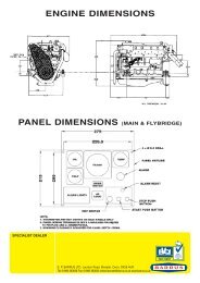
trapped air bubbles may be expelled. Top up the system as necessary.14. Calorifier• The temperature of coolant flowing to the calorifier from the engine can be between 85and 90°C. A blender valve must be incorporated in the calorifier/hot water system outletto lower the hot water temperature for domestic use.15. Control Cables• Connect engine speed control cable. With the engine off, ensure that the engine speedcontrol lever achieves full travel from idle to full speed. Adjust if necessary.• Check the gearbox shift lever selects positively and that the drive direction correspondswith the gearshift control lever. Ensure that the gearbox control lever and the gearshiftlever are both in neutral before connection. Adjust if necessary.16. Domestic Battery BankDomestic battery banks that are too large create excessive loads on the domesticalternator. Alternators running at maximum output for prolonged periods of time willeventually fail; alternators that fail due to the battery bank being over the maximumrecommended size will not be covered by warranty.Higher output alternators or travelpower kits are available; if larger battery banks arerequired discuss your individual power requirements with the boat builder.• The maximum domestic battery bank is calculated using the following:Live aboard, three times domestic alternator, maximum output current.Hire fleet use, three and a half times domestic alternator, maximum output current.If the engine is fitted with a <strong>Barrus</strong> approved alternator management system the domesticbattery bank can be up to four times the domestic alternator, maximum output current.Example:Hire fleet application fitted with 110 amp domestic alternator3.5 x 110 = 385 ampere/hour maximum battery bank size17. Control PanelAll Shire engines are supplied with high quality engine control panel that all show RPM andhours run and include warning lights and a warning buzzer, the deluxe panels also havegauges for water temp, oil pressure and battery charging. The panels are designed to besplash proof and are correctly installed with the gauges vertical.RDG6039039 - Issue 4 - Shire09 Complete Manual Page 18 of 45
SECTION 4 - Operation1. Starting the Engine for the First Time• Remove ignition key.• Ensure all oil and coolant levels are checked.• Ensure both engine and domestic batteries are connected or the blue link wire is inplace. Battery master switches must be turned on.• Check all connections and mountings are tight.• Ensure the red protection cap is removed from the air filter inlet.2. Starting Procedure• Ensure the gearshift control lever is set to neutral, and that persons are clear of anymoving parts.• Insert the ignition key.• Ensure the domestic battery isolator is turned to the on position before starting theengine, failure to do so may damage the domestic alternator.• Turn key to first position, run.• Observe warning lights (and gauges on deluxe panel).• Listen for warning buzzer.• Turn key to second position, start, and hold to crank.• Crank the engine for no more than 15 seconds.• On engine start, immediately release key.• Key will return to first position, run.• The warning buzzer will stop and on the deluxe panel the oil pressure gauge will showan oil pressure of 3.5 – 4.5 bar [51-65 psi].• Should any warning light not go out, or if there is no reading on the oil pressure gauge,the buzzer will continue sounding. In this case, stop the engine immediately and checkthe relevant system (Note: if the charge light does not go out, briefly increase theengine speed).RDG6039039 - Issue 4 - Shire09 Complete Manual Page 19 of 45
• Stop engine immediately if any abnormal noises are detected.• Visually check the engine for oil, fuel and coolant leaks, (after initial start up and atregular intervals, N.B. engine must be stopped to carry out this check).3. Stopping Procedure• Move speed control lever to idle position.• Turn key to off position.4. Full Load Running• Running diesel engines near their rated output (maximum load) regularly will disperseaccumulated carbon and condensation enhancing engine life and reducing emissions.• Running the engine at, or near, maximum speed whilst in gear may not be possible oninland waterways with speed limits in place. This will have to be carried out whilstmoored up. Ensure that the mooring ropes and posts are strong enough to allow this,and that the water is deep enough not to damage the propeller. It is recommended thatthe engine is run at or near full load for 15 minutes (maximum revs, in gear) every 50hours.5. Refuelling• All Shire canal boat engines run on Diesel fuel.• Please note that when the vessel is to be left for any period of time the fuel tank shouldbe left full to eliminate the build up of condensation and formation of water in the fueltank.6. Twin ThermostatsThe twin thermostat design is a feature unique to the Shire canal boat, engine range. Itensures that the engine warms up very quickly due to the first thermostat being closed sothat cooling water is routed through the specially designed cast iron exhaust manifold. Thewaste heat from the exhaust is recycled to bring the engine up to operating temperatureeven quicker than normal. This ensures efficient engine operation with reduced fuelconsumption and even cleaner exhaust emissions. It also helps in keeping engine wear toa minimum.The diagrams on the following page show the operation of the cooling system.RDG6039039 - Issue 4 - Shire09 Complete Manual Page 20 of 45
With the engine quickly up to operatingtemperature, the first 71° thermostatopens. The water now flows to thedomestic hot water tank, resulting in hotwater being rapidly available.When the water stored in the hot watertank has reached full temperature, thesecond 88° thermostat opens and watercan then flow to the skin tank andcorrectly control engine cooling. Theexhaust manifold that earlier helped toheat engine water is now cooled toensure safe operation and reduceengine compartment temperatures.If the load on the engine reduces andthe demand for domestic hot waterincreases then the system willautomatically compensate and re-directwater to ensure that a plentiful supply ofhot water is always available.Figure 4-1: Twin Thermostat OperationRDG6039039 - Issue 4 - Shire09 Complete Manual Page 21 of 45
7. Diesel Fuel AdditiveThe use of diesel fuel additive is strongly recommended on Shanks & Shire engines.The quality of the fuel available when cruising is often unknown; also the fuel mayhave been in storage for long periods of time. The use of additives will ensure thatyour engine fuel injection system is in top condition which should result in manyyears of smooth reliable operation without the cost and inconvenience of expensivebreakdowns due to poor quality fuel. It has also been found that improvements infuel consumption and startability are an added benefit of using this product.Diesel fuel additive is available from your Shanks or Shire dealer in a handy 470mlcontainer, part number <strong>EP</strong>B5607.8. Exhaust Back PressureThe back pressure falls within the manufacturers recommended range when usingthe exhaust system supplied with the engine.RDG6039039 - Issue 4 - Shire09 Complete Manual Page 22 of 45
SECTION 5 - Service Procedure1. Engine Oil and Filter ChangeCAUTION:WEAR DISPOSABLE GLOVES AND BEWARE OF HOT OIL AND <strong>ENGINE</strong> BLOCK.REMOVE THE IGNITION KEY BEFORE WORKING IN <strong>ENGINE</strong> COMPARTMENT.• Change the engine oil while the engine is still hot.• Remove the blanking plug in the sump pump spout. [6mm Allen key] Note: Shire 50 hastwo oil drain pumps, it is the pump mounted up higher on the engine.• Place a plastic tube over the spout and into a container. Operate the pump handle toempty the sump. (Remember to refit the blanking plug afterwards).• Place a drip tray under the engine to catch the small amount of oil that will escape fromthe oil filter. Using the strap type oil filter removal tool (supplied), slacken the filter fromthe engine block in an anti clockwise direction, remove the tool and spin off the filter.• Lightly oil the new filter O ring seal and install the filter onto the engine. Spin it on in aclockwise direction and finally tighten by hand only as firmly as you can.• Refill the sump using the yellow oil filler cap in the rocker cover on top of the engine.• Oil level should be to the top mark on the dipstick.• Run the engine for 5 minutes to fully circulate the oil, and check for leaks, stop theengine. Wait 5 minutes before checking the oil level with the dipstick and top up ifrequired.• Do not exceed maximum oil level marker as this may cause damage to the internalcomponents of the engine.2. Air Filter Check & ChangeCAUTION:WEAR DISPOSABLE GLOVES AND BEWARE OF HOT <strong>ENGINE</strong> BLOCK.REMOVE THE IGNITION KEY BEFORE WORKING IN <strong>ENGINE</strong> COMPARTMENT.• Release the two spring clips, pull off the end cover to reveal the filter element. Theelement simply pulls out.• To fit the new element, slide the open end of the filter element into the main body;gently push the element until fully seated. Refit the end cover.• The air filter element is constructed from pleated paper; inspect it closely for dust or dirt.RDG6039039 - Issue 4 - Shire09 Complete Manual Page 23 of 45
The air filter cannot be cleaned and must be replaced when dirty. The engine requiresclean unrestricted air to run efficiently, failure to maintain the air filter could result insmoke, increased fuel consumption and ultimately engine damage.3. Gearbox Oil ChangeCAUTION:WEAR DISPOSABLE GLOVES AND BEWARE OF HOT OIL AND GEARBOX CASINGS.REMOVE THE IGNITION KEY BEFORE WORKING IN <strong>ENGINE</strong> COMPARTMENT.NOTE: Certain engines will have a gearbox sump pump fitted, to change the oil in thiscircumstance, follow the same procedure as was outlined for changing the engine oil. Forengines without a gearbox sump pump, follow the procedure below.• Change the gearbox oil while it is still hot.• Place a tray beneath the gearbox that will hold at least 5.0 litres.• Some engines may have a gearbox drain pump fitted, either as standard or as anoption, therefore removal of drain plug is not required.• Undo the gearbox drain plug and remove, allow the oil to drain fully. MA100A andMA125A gearboxes have a magnetic drain plug, ensure any swarf is cleaned off. It isnot uncommon for these gearboxes to generate a small amount of swarf, particularlywhen new.• Replace the drain plug, ensure that the sealing washer (if used) is still in place, and ingood condition, tighten. Fit a new washer if required.• Refill the gearbox with oil to the upper mark on the dipstick. Screw dipstick in fully toestablish level. The gearbox uses the same oil as the engine.• Do not overfill gearbox as this can damage the internal components.Dipstick andrefill holeFigure 5-1: MA100A GearboxMagnetic drain plugRDG6039039 - Issue 4 - Shire09 Complete Manual Page 24 of 45
Refill holeMagnetic drain plugFigure 5-2: MA125A GearboxLevel dipstick /filler plugFigure 5-3: PRM150 GearboxLevel dipstick /filler plugFigure 5-4: PRM260 GearboxRDG6039039 - Issue 4 - Shire09 Complete Manual Page 25 of 45
4. Gearbox Hydraulic Oil Filter (MA100A and MA125A models)CAUTION:REMOVE THE IGNITION KEY BEFORE WORKING IN THE <strong>ENGINE</strong> COMPARTMENT.• Check gearbox oil level weekly and at recommended service period remove filterand clean.• Drain gearbox oil. Remove the banjo bolt going into the filter and ease the adjacentbanjo bolts and pipe (as shown Figure 5-5 to allow access to the filter).• Remove filter; clean and replace.• Ensure sealing washers are in good condition.• Refit the banjo bolt.• Refill gearbox with 4.8L (MA125A) or 2L (MA100A) of 15W40 CD grade oil.• Check filter head to ensure that there are no leaks.Hydraulic gearbox filterBanjo boltsRDG6039039 - Issue 4 - Shire09 Complete Manual Page 26 of 45
Figure 5-5: Hydraulic Gearbox Oil Filter (MA100A and MA125A)5. Disposal of Oil and Related Items• Please dispose of used oil and oil filters safely with due regard for the environment andtake to your local waste oil disposal point.• Do not allow oil or contaminated parts to enter the inland water way system.6. Primary Fuel Filter Water DrainCAUTION:WEAR DISPOSABLE GLOVES.REMOVE THE IGNITION KEY BEFORE WORKING IN <strong>ENGINE</strong> COMPARTMENT.• Place a small drain bowl under the primary fuel filter/water trap.• Loosen the drain screw located in the bottom of the fuel filter/water trap (Figure 5-6).• Drain off any water.• Once the water has been drained - re-tighten the drain screw.• It is unlikely the complete fuel system will require bleeding.• Ensure the fuel tank is full prior to bleeding the fuel system.• Run for 5 minutes.• Check that the drain union is tight and that there are no leaks.• Note: the boat builder may have fitted an additional water trap in the fuel system beforethe engine.Figure 5-6: Primary Fuel Filter Drain ScrewRDG6039039 - Issue 4 - Shire09 Complete Manual Page 27 of 45
7. Primary and Secondary Fuel Filter ChangeCAUTION:WEAR DISPOSABLE GLOVES.REMOVE THE IGNITION KEY BEFORE WORKING IN <strong>ENGINE</strong> COMPARTMENT.• Ensure the fuel tank is at least ¾ full prior to undertaking this procedure.• Turn off the main boat fuel supply tap, located on or near the fuel tank.• Place a small drip tray under the filter body.• Remove the fuel filter in the same way as the oil filter in part 1 of section 5.• Primary fuel filter only – Retain the metal fuel filter drain screw from old filter and re-usein the new filter.• Remove and smear a small amount of clean fuel on all of the O ring seals that aresupplied with the new filter element.• Screw the new element back into the filter head.• Turn the main boat fuel supply tap back on.• Ensure system is correctly bled before attempting start up.The same procedure is used for both Primary and secondary fuel filter changes8. Fuel System Bleeding• Ensure the fuel tank is at least ¾ full prior to undertaking this procedure.• See Fuel paragraph, Section 3, in Yanmar Engine Operation Manual.9. Cooling System• To check the coolant level, ensure that the engine has been shut down for at least halfan hour.• The coolant level can be checked visually and should between the two level marksformed on the front of the white, plastic expansion tank.• If required, top up the level with coolant (60% clean tap water and 40% ethylene glycolbased anti-freeze) through the expansion tank filler cap.• Do not use water only to top up mix as this weakens the coolant mix, reducing the levelof frost protection and anti-corrosion protection of the coolant.10. Belt AdjustmentCAUTION:REMOVE THE IGNITION KEY BEFORE WORKING IN <strong>ENGINE</strong> COMPARTMENT.• Depress the longest run of the drive belt to be checked. If the travel exceeds 15 -20mmRDG6039039 - Issue 4 - Shire09 Complete Manual Page 28 of 45
using hard finger pressure, the belt needs re-tensioning.• Loosen the upper adjuster bolts on the alternator, and the lower mounting pivot nut andbolt, either pull out using hand pressure or use the tensioning screw, depending onwhich alternator belt is to be tensioned.• Pull the alternator away from the engine to tighten the belt.• Hold the alternator in position and re-tighten all the bolts.• Note: if the belts are over tightened alternator bearing failure will occur.11. Belt Maintenance• Do not allow oil to contact the belt. Oil attacks the construction of the belt, reduces thedrive efficiency and will ultimately cause it to fail prematurely.• Replace the belt if it cracks or splits and as the adjustment nears the limit of its travel.• Note: Some boat builders may remove one or more of the alternators during theinstallation of the engine. It is essential that when the alternators are re-fitted that thealignment is perfect or premature wear will occur.12. Belt ReplacementCAUTION:REMOVE THE IGNITION KEY BEFORE WORKING IN <strong>ENGINE</strong> COMPARTMENT.• Ensure that you have the correct replacement belts before starting this procedure.Some customers may have engines fitted with non standard optional alternators whichmay not have the standard belts listed. Make a note of the belt sizes on delivery.• Loosen the top adjuster bolts, and the lower mounting pivot nut and bolt.• Push the alternator towards the engine to loosen the belt.• Remove the belt.• Hold the belt in position over the top alternator pulley; rotate the engine if required, byhand, to guide the new belt into the “vee”.• Re-tension the belt as above.13. Basic and Standard Panel MaintenanceCAUTION:REMOVE THE IGNITION KEY BEFORE WORKING IN <strong>ENGINE</strong> COMPARTMENT.TURN BATTERY ISOLATION SWITCHES OFF.Bulb replacementRDG6039039 - Issue 4 - Shire09 Complete Manual Page 29 of 45
Release the panel from its mounting1. To replace a tacho meter illumination bulb.a. The tacho bulb is accessible from the rear of the panel and is retained by a blackplastic holder with a bayonet fitting. This can be gently removed by rotating witha pair of pointed nose pliers.2. To replace a warning light bulb.a. The warning light bulbs are accessible from rear of the panel.b. The bulb retainers (3 off) are simply prized from their retaining block.14. Deluxe Panel MaintenanceCAUTION:REMOVE THE IGNITION KEY WHILE WORKING IN <strong>ENGINE</strong> COMPARTMENT.TURN BATTERY ISOLATION SWITCHES OFF.1) Warning light bulb replacementa. The warning light bulbs are accessible from the front of the panel.b. Carefully prise out the coloured lensc. With needle nose pliers, remove the clear lens to reveal the bulbd. The capless bulb is a push fit in the holder2) To replace a Tachometer illumination bulb.a. Unscrew and pull out the instrument panel.b. The tacho bulb is accessible from the rear of the panel and is retained by a blackplastic holder with a bayonet fitting.c. Removed by rotating half a turn with a pair of pointed nose pliers.d. The capless bulb is a push fit in the holder.3) To replace a Gauge illumination bulb.a. Unscrew and pull out the instrument panel.b. The illumination bulb holder is a push fit in the rear of the gauge.c. The capless bulb is a push fit in the holder.4) To replace a Gauge warning light bulb.a. Unscrew and pull out the instrument panel.b. The warning light bulb holder is a push fit in the rear of the gauge, but is retainedby a plastic clip. Gently push the clip to one side to release the holder.c. The capless bulb is a push fit in the holder.d. Ensure that on refitting, the bulb holder is retained by the clip, you should confirmcorrect positioning when the clip “clicks” when locked.RDG6039039 - Issue 4 - Shire09 Complete Manual Page 30 of 45
GEARBOXOILCAPACITY(EXCLUDINGCOLER): 40, 40H,45, 45H,50 7.4 13Gearbox PRM150 PRM260Capacity(Litres)Capacity(Pints) 1.4 1.5 2.5 2.7EngineandGearboxOil:SAE15W40APIMA10A 2 3.5Colant:60%CleanWater+40%EthyleneGlycolMA125A 4.8 8.4MA125AandMA10Agearboxeshaveruningpresuresofbetwen1and1.3MPa(10ClasCD.and13Bar)andinitialAntifreze.ServiceIntervalsoil presuresofbetwen0.15and0.4MPa(1.5and4Bar).EngineOil CheckChange NotesGearboxOil&FilterDaily(level)Every250hoursWeklyOr12Months*Firstchangeafter50hrs SECTION 6 - Service ScheduleGearboxOil Hydraulic(level)Every250hours(level)Every40hoursRemove&cleanmagnet Or12Months*Firstchangeafter25hrsGearboxOil DieselHydraulicCleanevery40hrs (MA10A&MA125AOnly)Primaryand Fuel FilterAirFilterElement250HoursEvery50hours Secondary50hoursEvery50hours Or12Months*Drainwaterevery50hours,*Whicheverocursfirst. Drivebelts DailyAsrequiredAdjustasnecesary Or24Months*Sonerifrequired Specifications ormonthly# and Capacities#Iflargequantitiesofwaterarefoundinfuel draining. whenfilterdrained, increasefrequencyof<strong>ENGINE</strong> OIL CAPACITY (WITH FILTER):Engine Capacity (litres) Capacity (Pints)RDG6039039 - Issue 4 - Shire09 Complete Manual Page 31 of 45
SECTION 7- Wiring Diagrams1. Engine Wiring Diagram Shire 40HRDG6039039 - Issue 4 - Shire09 Complete Manual Page 32 of 45
2. Engine Wiring Diagram Shire 45, 45H & 50 (& Shire 40 with optional160A Alt)RDG6039039 - Issue 4 - Shire09 Complete Manual Page 33 of 45
3. Standard Panel Wiring DiagramRDG6039039 - Issue 4 - Shire09 Complete Manual Page 34 of 45
4. Deluxe Panel Wiring DiagramRDG6039039 - Issue 4 - Shire09 Complete Manual Page 35 of 45
5. RDG5775 Standard PanelOil Pressurewarning lightWater temperaturewarning light50A Alternatorcharge light110A Alternatorcharge lightIgnition switchHourmeterTachometerRDG6039039 - Issue 4 - Shire09 Complete Manual Page 36 of 45
6. RDG5768 Deluxe Panel50A Alternator chargewarning light50A Alternator voltageoutput gauge110A/160A Alternatorcharge warning lightIgnition switchHourmeterTacho-meterWatertemperaturewarning lightWatertemperaturegaugeOil pressurewarning lightOil pressuregaugeRDG6039039 - Issue 4 - Shire09 Complete Manual Page 37 of 45
7. VDO 7KW Wiring Diagram and Overall DimensionsShire Canal Boat EngineVDO 7KW 05 - Wiring Diagram12-24 VoltSchematic only Do not scale© E. P. <strong>Barrus</strong> Ltd Issue 1Remote Control(Rocker Switch)8 723BlackFuse 5ARedGreen/White123455 Pin PlugTo VDOBoxFuse 1AConnects to existing2Engine Loom1HereBlackRedGrey3124Red/WhiteWhite/Black31244 321View from backof plug(Converter side)BlackBlueRed12-24VConverterNote: All conductorshave a 5A currentrating.Figure 7-1: Travelpower wiring diagramThe above diagram shows 12/24 Volt part of the wiring for the 7KW VDO Travel Powersystem. For the 230 Volt wiring diagram please refer to the VDO Travel Power manual.WARNING:ALL HIGH VOLTAGE WIRING SYSTEMS SHOULD BE INSTALLED BY AQUALIFIED ELECTRICIAN.8. 5kW VDO Travel Power System• This unit is excited by a 12v ignition operated supply the travel power installer canwire to a convenient plug on the existing loom for this purpose.• When the 12v relay (RDG1396) is placed into the spare relay holder on the enginethe black two way plug becomes live.• The wire colours in the plug are: Black - EarthRed - LiveRDG6039039 - Issue 4 - Shire09 Complete Manual Page 38 of 45
Figure 7-2: Travelpower dimension reference diagramSizes for the dimensions listed in figure 7-2 are as follows:3.5kW 5kW 7kWDim 1 65mm 65mm 55mmDim 2 390mm 390mm 470mmDim 3470mmDim 480mmNOTE: ‘DIM 3’ and ‘DIM 4’ dimensions stated in the above table refer to the dimension fora 160amp alternator. If a 110amp alternator is fitted here, ‘DIM 3’ would read 370mm and‘DIM 4’ would read 130mm.RDG6039039 - Issue 4 - Shire09 Complete Manual Page 39 of 45
SECTION 8 - General Arrangement Drawings1. General Arrangement Shire 40H (MA100A Gearbox)RDG6039039 - Issue 4 - Shire09 Complete Manual Page 40 of 45
2. General Arrangement Shire 45HRDG6039039 - Issue 4 - Shire09 Complete Manual Page 41 of 45
3. General Arrangement Shire 45/50 (PRM150 Gearbox)RDG6039039 - Issue 4 - Shire09 Complete Manual Page 42 of 45
4. General Arrangement Shire 45/50 (PRM260 Gearbox)RDG6039039 - Issue 4 - Shire09 Complete Manual Page 43 of 45
SECTION 9 – Dealer ListCountry Area Company Telephone EmailENGLAND BERK<strong>SHIRE</strong> Bluenine Marine 01189 406482 bluenine@marine7957.fsnet.co.ukReading Marine Co. Ltd 01189 713666 enquiries@readingmarine.co.ukCHE<strong>SHIRE</strong> Nantwich Canal Centre 01270 625122 info@nantwichcc.comCORNWALL Cellar Marine 01326 280214 john@cellarmarine.comDERBY<strong>SHIRE</strong> Midland Canal Centre 01283 701933 info@mccboats.co.ukDEVON Sleeman & Hawkin Ltd 01626 778266 keith@sleeman-hawkin.co.ukESSEX French Marine Motors Ltd 01206 305233 chris@frenchmarine.com01255 850303 info@frenchmarine.comHAMP<strong>SHIRE</strong> Marine Power Ltd 0238 0403918 info@marine-power.co.ukHERTFORD<strong>SHIRE</strong> P & S Marine 01923 248372LEICESTER<strong>SHIRE</strong> Foxton Boat Services Ltd 01162 792285 tony@foxton-boats.freeserve.co.ukLONDON De La Hunty Marine 02089 792121 delahuntymarine@btinternet.comNORFOLK French Marine Motors Ltd 01603 722079 info@frenchmarine.comNORTHAMPTON Grand Junction Boat Co. 01604 858043 grandjunco@talk21.comNOTTINGHAM Farndon Marina 01636 705483 info@farndonmarina.co.ukSTAFFORD<strong>SHIRE</strong> JD Boat Services Ltd 01902 791811 jdboats@btinternet.comStone Boatbuilding Company 01785 812688 sales@stonebuilding.co.ukStreethay Warf 01543 414770 pat@streethaywarf.freeserve.co.ukWARWICK<strong>SHIRE</strong> Barry Hawkins Narrowboats 01827 711762 boats@hawkinsyard.freeserve.co.ukValley Cruises Ltd 02476 393333 sales@onboardenergy.comWEST MIDLANDS Stephen Goldsbrough Boats 01564 778210 andy@sgboats.comWORCESTER<strong>SHIRE</strong> J L Pinder & Son 01527 876438 sales@jlpinderandsons.co.ukStarline Narrowboats 01684 874774 narrowboats@starline.demon.co.ukYORK<strong>SHIRE</strong> Ledgard Bridge Boat Company 01924 493844 mail@ledgardbridge.comRodley Boat Centre 01132 576132 John.snowdenz@ntlworld.comWALES MONMOUTH<strong>SHIRE</strong> Castle Narrowboats 01873 830001 castlenarrowboats@btinternet.comEIRE Dun Laoghaire Marine Services 00353 12104776O’Sullivans Marine 003536 67124524 brian@sulliansmarine.comRDG6039039 - Issue 4 - Shire09 Complete Manual Page 44 of 45
SECTION 10 – Shire Service PartsModel 40H 45H 50Primary FuelFilterSecondaryFuel FilterRDG9188346 RDG9188346 RDG9188346119802-55800 119802-55800 119802-5580050A Alt Belt RDG6079 RDG6079 RDG6079110A Alt BeltRDG0048974160A Alt Belt RDG0047859 RDG0047859Air FilterElementRDG5795 RDG5795 RDG5795Oil Filter 129150-35152 129150-35152 129150-35152FusesThe electrical system is fitted with three or fourblade type fuses,a. Engine start control system 25amp (RDG1152)b. Engine stop control system 40amp (RDG3246)c. Dash Panel supply 15amp (RDG3245)d. 7kw Alternator sub-system 15amp (RDG3245)**** Only fitted on to engines with the optional VDO travelpower 7kW (EE) alternator.Starter Relaya. 25Ab. 40Ad. 15Ac. 15AOptional7 kW Relay3.5kw VDO Electrolux Travel power alternator belt is RDG6076.5kw VDO Electrolux Travel power alternator belt is RDG6076.7kw VDO Electrolux Travel Power alternator belt is RDG6082.Engine Oil is available from your Shire dealer in convenient 5 litre containers. Part numberRDG6110.Diesel fuel additive is available from your Shire dealer in a handy 470ml container, partnumber <strong>EP</strong>B5607.RDG6039039 - Issue 4 - Shire09 Complete Manual Page 45 of 45