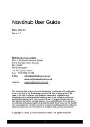
NAV-490 490kHz NAVTEX Converter User Guide (MAN3025.00)
NAV-490 490kHz NAVTEX Converter User Guide (MAN3025.00)
NAV-490 490kHz NAVTEX Converter User Guide (MAN3025.00)

You also want an ePaper? Increase the reach of your titles
YUMPU automatically turns print PDFs into web optimized ePapers that Google loves.
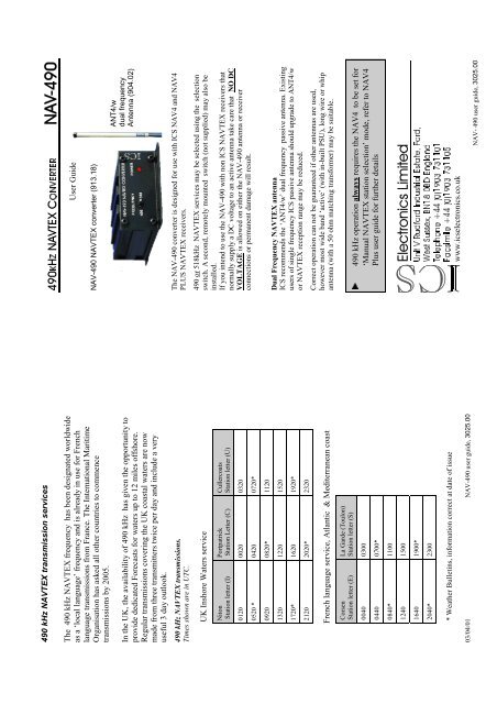
<strong>490</strong> kHz <strong>NAV</strong>TEX transmission servicesThe <strong>490</strong> kHz <strong>NAV</strong>TEX frequency has been designated worldwideas a ‘local language’ frequency and is already in use for Frenchlanguage transmissions from France. The International MaritimeOrganisation has asked all other countries to commencetransmissions by 2005.In the UK, the availability of <strong>490</strong> kHz has given the opportunity toprovide dedicated Forecasts for waters up to 12 miles offshore.Regular transmissions covering the UK coastal waters are nowmade from three transmitters twice per day and include a veryuseful 3 day outlook.<strong>490</strong> kHz <strong>NAV</strong>TEX transmissions.Times shown are in UTC.UK Inshore Waters serviceNitonStation letter (I)PortpatrickStation Letter (C)CullercoatsStation letter (U)0120 0020 03200520 * 0420 0720*0920 0820* 11201320 1220 15201720* 1620 1920*2120 2020* 2320French language service, Atlantic & Mediterranean coastCorsenStation letter (E)La Garde (Toulon)Station letter (S)0040 03000440 0700*0840* 11001240 15001640 1900*2040* 2300* Weather Bulletins, information correct at date of issue03/04/01<strong>NAV</strong>-<strong>490</strong> user guide, 3025.00.+=1$97(;&219(57(51$9<strong>User</strong> <strong>Guide</strong><strong>NAV</strong>-<strong>490</strong> <strong>NAV</strong>TEX converter (913.18)ANT4/wdual frequencyAntenna (904.02)The <strong>NAV</strong>-<strong>490</strong> converter is designed for use with ICS <strong>NAV</strong>4 and <strong>NAV</strong>4PLUS <strong>NAV</strong>TEX receivers.<strong>490</strong> or 518kHz <strong>NAV</strong>TEX services may be selected using the selectionswitch. A second, remotely mounted switch (not supplied) may also beinstalled.If you intend to use the <strong>NAV</strong>-<strong>490</strong> with non ICS <strong>NAV</strong>TEX receivers thatnormally supply a DC voltage to an active antenna take care that NO DCVOLTAGE is allowed on either the <strong>NAV</strong>-<strong>490</strong> antenna or receiverconnections or permanent damage will result.Dual Frequency <strong>NAV</strong>TEX antennaICS recommends the ‘ANT4/w’ dual frequency passive antenna. Existingusers of single frequency ICS passive antenna should upgrade to ANT4/wor <strong>NAV</strong>TEX reception range may be reduced.Correct operation can not be guaranteed if other antennas are used,however most wide band ‘active’ (with in-built PSU), long wire or whipantenna (with a 50 ohm matching transformer) may be suitable.‡ <strong>490</strong> kHz operation always requires the <strong>NAV</strong>4 to be set for‘Manual <strong>NAV</strong>TEX station selection’ mode, refer to <strong>NAV</strong>4Plus user guide for further details(OHFWURQLFV/LPLWHG8QLW 9 5XGIRUG ,QGXVWULDO (VWDWH )RUG:HVW 6XVVH[ %1 %' (QJODQG7HOHSKRQH )DFVLPLOH www.icselectronics.co.uk<strong>NAV</strong>- <strong>490</strong> user guide, 3025.00
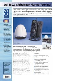
1InstallationMounting:Locate the <strong>NAV</strong>-<strong>490</strong> in a ‘dry’ location close to the <strong>NAV</strong>TEXreceiver. Two x 4.5 mm diameter fixing holes are provided at eachend. To gain access to the rear holes you may need to unplug theorange connector.Connections:• Connect the ANT4/w (904.02) dual frequency’ <strong>NAV</strong>TEXantenna to the orange connector. Pin 1 - antenna signal, pin 2 -antenna ground.• Connect the coaxial ‘link’ cable to the <strong>NAV</strong>TEX receiverantenna input (<strong>NAV</strong>4 pins 1 & 2 , remove the existing antennafirst). The ‘red spot’ on the connector identifies the antennasignal pin which must be connected to <strong>NAV</strong>4 pin 1.• Connect the power wires to a ‘SWITCHED’ 10 –30 VDCsupply or via a 1 Amp circuit breaker.RED wire to POSITIVE, BLACK wire to NEGATIVE.ANTENNAWARNING:There must be NO VOLTAGEpresent on the antennaconnections1<strong>NAV</strong>4<strong>NAV</strong>TEXRECEIVER10(BLACK) -+ (RED)POWERSUPPLY(10V to 30V)EXTERNALSWITCH(OPTIONAL)8<strong>NAV</strong>-<strong>490</strong> <strong>NAV</strong>TEX CONVERTERA remotely mounted <strong>NAV</strong>TEX frequency selection switch (notsupplied) may be fitted to allow remote frequency switching. To usethis feature, connect a ‘single pole’ switch across connection pins 7& 8. The remote switch cable should not exceed 2M in length.• The remote switch ‘contact closure’ selects 518kHzTo enable the remote switch, always leave the in-built switch in the<strong>490</strong> position.OperationConfirm that the <strong>NAV</strong>-<strong>490</strong> power LED is ON.Use the frequency selection switch to select the required <strong>NAV</strong>TEX service.Confirm that the <strong>NAV</strong>TEX receiver is turned on and the appropriate<strong>NAV</strong>TEX station and message categories are selected.Note that <strong>NAV</strong>4 PLUS users must set the <strong>NAV</strong>4 to ‘Manual <strong>NAV</strong>TEXstation selection’ mode when attempting <strong>490</strong>kHz reception.Dimensions (mm)65W x 115D x 32HWeight: 0.2kg65Operating CharacteristicsVoltage: 10 - 30VDCPower: 60mA @ 12VDCTemperature range: 0 - 40°Cdia 4.5ControlsToggle switch allows either <strong>490</strong>kHz or 518kHztransmissions to be selected.MountingDesigned for flush mounting on a flat panel withplug in connector strip protruding from the rear.ConnectionsEight way, two part screw terminal connector.Connection pin assignments12345678932100115FREQUENCY50POWER<strong>490</strong>5181$9 1$97(; &219(57(5PIN Description913.18 <strong>NAV</strong>-<strong>490</strong> Packing list:1 <strong>490</strong> / 518kHz antenna2 Antenna ground3 518kHz output to<strong>NAV</strong>TEX receiver4 Output ground5 Power supply ground• <strong>NAV</strong>-<strong>490</strong> <strong>NAV</strong>TEXconverter• Cable harness with 2 metresof cable and orangeconnector• This instruction sheet6 Power supply input+ 10-30VDC7 Remote switch ground8 Remote switch contact,OPEN = <strong>490</strong> kHzreceptionNote:‡ The <strong>NAV</strong>-<strong>490</strong> should notbe used by GMDSS -<strong>NAV</strong>TEX mandatory fitvessels.