Digital synthetic-heterodyne interferometric demodulation
Digital synthetic-heterodyne interferometric demodulation
Digital synthetic-heterodyne interferometric demodulation

You also want an ePaper? Increase the reach of your titles
YUMPU automatically turns print PDFs into web optimized ePapers that Google loves.
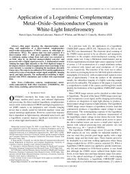
MJConnellyModulation currenti( t)= Imcos ω0tDFB laserdc biasI(t)Bias-teeIsolatorOpticalreceiverSplitterOptical fibre<strong>Digital</strong>signalprocessingExtrinsic cavityR 2R 1PressurewaveLensFlexibleL mirrorOutput signalproportional todynamic pressureFigure 1. Dynamic pressure sensor system using <strong>synthetic</strong> <strong>heterodyne</strong> <strong>demodulation</strong>.XFIR low-passfilterFromopticalreceiverAmplifierAnti-aliasingfilterADCCos(w t)0Cos(2w t) 0XFIR low-passfilterddtddtXX+ IntegratorResetswitchAmplifierRange checkDACAnalogoutputto low-passfilter0Figure 2. Synthetic-<strong>heterodyne</strong> <strong>demodulation</strong> digital implementation.τ c is related to the laser spectral linewidth ν byτ c = 1ν . (19)The quantization noise current spectral density is given by( VA–D/2 Q) 2G q =6T s R 2 (20)Lwhere V A–D and Q are the voltage range and number of bits ofthedigitalsignal processor input ADC. T s is the sampling time(inverse of the sampling frequency). In (20) it is assumed thatunity strength sampling pulses are used in the ADC quantizer.The total current noise spectral density η (single-sided) atthe ADC input is simply the sum of the individual uncorrelatednoise spectral densities, i.e.η = G th + G p + G q . (21)η can be considered to be white noise over the bandwidth ofthe detection process. It is an elementary but tedious process,using techniques described in [7], to calculate the output noisepower N after<strong>synthetic</strong>-<strong>heterodyne</strong> <strong>demodulation</strong>. We simplystate the result here:N = [AV J 2(C)] 2 ηB. (22)23.2. Output signal powerIf the input phase signal φ(t) is sinusoidal with amplitude Dandangular frequency ω s ,thenthe detected signalpower,afterintegration of S 0 ,isgivenbyS = (AV)4 [DJ 1 (C)J 2 (C)] 2. (23)2The sensor signal-to-noise ratio (SNR), from (22) and (23) isgiven bySNR ≡ S N = [AV J 1(C)D] 2. (24)ηBThe sensor sensitivity can be defined as the phase amplitudeD min required for an SNR of unity. From (24) we get√ ηD min =rad Hz −1/2 . (25)AV J 1 (C)If laser phase noise induced intensity noise is dominant, thenD min is proportional to the cavity length.4. Second-harmonic distortionThe laser power varies as the current is modulated. This cancause phase errors [8]. In <strong>synthetic</strong>-<strong>heterodyne</strong> <strong>demodulation</strong>,S402