Start Italiana "Level Management System 2008".
Start Italiana "Level Management System 2008".
Start Italiana "Level Management System 2008".

Create successful ePaper yourself
Turn your PDF publications into a flip-book with our unique Google optimized e-Paper software.
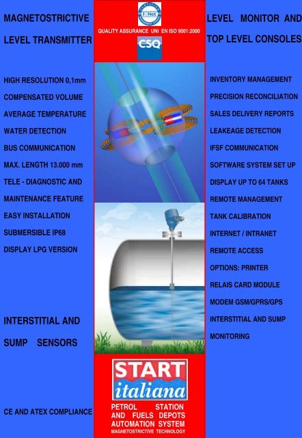
MAGNETOSTRICTIVELEVEL TRANSMITTERQUALITY ASSURANCE UNI EN ISO 9001:2000LEVEL MONITOR ANDTOP LEVEL CONSOLESHIGH RESOLUTION 0,1mmCOMPENSATED VOLUMEAVERAGE TEMPERATUREWATER DETECTIONBUS COMMUNICATIONMAX. LENGTH 13.000 mmTELE - DIAGNOSTIC ANDMAINTENANCE FEATUREEASY INSTALLATIONSUBMERSIBLE IP68DISPLAY LPG VERSIONINTERSTITIAL ANDINVENTORY MANAGEMENTPRECISION RECONCILIATIONSALES DELIVERY REPORTSLEAKEAGE DETECTIONIFSF COMMUNICATIONSOFTWARE SYSTEM SET UPDISPLAY UP TO 64 TANKSREMOTE MANAGEMENTTANK CALIBRATIONINTERNET / INTRANETREMOTE ACCESSOPTIONS: PRINTERRELAIS CARD MODULEMODEM GSM/GPRS/GPSINTERSTITIAL AND SUMPSUMPSENSORSMONITORINGCE AND ATEX COMPLIANCEPETROL STATIONAND FUELS DEPOTSAUTOMATION SYSTEMMAGNETOSTRICTIVE TECHNOLOGY
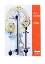
MAGNETOSTRICTIVE LEVEL TRANSMITTEROPERATING PRINCIPLEThe operating principle of magnetostrictive level gauges isbased on a physical property named “ W i e d e m a n n effect” .This technology allows the continuously reading of liquid levelwith very high accuracy. Our DIGIMAG level transmitter is mainlyconstituted by a microprocessor electronic circuit positioned ina n aluminium ex- proof box on the top of the stainless steeltube having in its internal part a waveguide fitted in the tank.A mechanical pulse caused by the magnetostrictive t w i s tstrain is generated in the exact meeting point with themagnetic field of the permanent magnet kept into floats.The mechanical pulse propagates into the waveguideat sound speed up to the sensor located in the measuringhead. The measurement of the time between the initial pulseand the back pulse exactly defines the position of the floats.MAIN FEATURESMicroprocessor electronic, no field calibration requiredPossibility to substitute internal sensor without removal waveguide from the tankPipe sensor in stainless steel AISI 304/316LMeasure range up to 6 metersProcess connections to tank: adjustable threaded connectionDigital outputs data for :- level of liquid in 0,1 mm- interface (water detection) in mm- temperatureP V C o r S p a n s i l FloatsP r o b e :- accuracy:± 0,5mm- resolution ± 0,1mmTemperature :- accuracy:± 0,2mm (ref. measuring range – 2 0 + 4 0 °C)- resolution ± 0,0625mmSupply voltage: 9 ÷ 30 Vdc < 3 0 m ASerial output RS 485Tele- diagnostic and Tele- maintenance by GSM / InternetAverage product temperature up to 10 digital sensorsExplosion proof ATEX CESI and INERIS - OIML R85(pending)CEComplianceOPERATING PRINCIPLEDIGIMAG XMTTEMPERATURE ERROR CURVEDIGIMAG XMT IP68
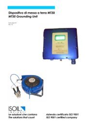
MAGNETOSTRICTIVE TRIPLE FUNCTIONS:LEVEL INDICATORLEVEL SWITCHLEVEL TRANSMITTERFOR LPG APPLICATIONLOCAL DISPLAY DIGITAL INDICATORLEVEL TRANSMITTER WITH N.3 SERIAL PORT OUTPUTLEVEL SWITCH WITH N.4 RELAIS OUTPUTDOUBLE SUPPLY: EXTERNAL OR BATTERY OPERATEDIT CAN SUBSTITUITE THE OBSOLETE MECHANICALGAUGE: WHEN TO FAIL EXTERNAL SUPPLYTHE MEASURE IS GUARANTIES BY AN INTERNALBATTERY WITH READING ON DEMANDAlphanumerical backlight display 16x2 lines ,Painted aluminium case IP 68 remote mountingContemporaneous visualization of:- product level in m m- volume in litres ( calibration chart via software via PC)- compensated volume 15°C- configurable 0÷ 100 % bar-graph- sensor diagnostic and alarms statusMeasurement accuracy ± 0 , 5 m mResolution ± 0 , 1 m mFour programmable r e l è outputs NO/NC 1A max.Two serial port RS485 for bus communicationOne serial port RS 232 for system set upPre arrangement for t e l e -diagnosis and tele- maintenancePower supply 9 ÷ 30 VDC and PP3 internal battery 9VDCExplosion proof ATEX CESI and INERIS - OIML R85(pending)CEComplianceAvailableoptional:- Average product temperature up to 10 digital sensors- Second float to detect and measure second liquid ( water, wastes)DIGIMON UP TO FOUR RELAISOUTPUTEExd ATEX DISPLAY PLUSVERSIONMAGNETOSTRICTIVE LEVELINDICATOR / TRANSMITTER
TECNICHAL FEATURESTank Connections:Adjustable threaded: ½ ” shaft 1 4 m m a n d ¾” s h a f t 1 7 m mElectrical Connections:Cable Gland EExd ½”N P T I P 6 8Guide rod in AISI 304 / 316L:M o d e l l o D I G I M A G X M T / D I G I M O N X M T :Ø 1 4 x 1 , 5 m m m a x i m u m l e n g t h 4 . 0 0 0 m mØ 1 4 x 2 , 0 m m m a x i m u m l e n g t h 6 . 0 0 0 m mFloats:S P -P P r o d u c t f l o a t 5 0 x 5 0 m mS P -A W a t e r f l o a t 5 0 x 5 0 m mTemperature:Liquid : - 45° C + 1 3 0° CH e a d : - 2 5 + 8 5° CA T E X version: -2 5 + 6 0° CMedia Viscosiy: < 1 0 0 CpCable:Twisted double, shield , e x t e r n a l m i n .Ø 8 m mm o d . F R X H H 2 R N P I 2 x 2 x 0 , 5 0Power Supply:Battery Operated 9 V t i p o P P 3External supply : 9 -3 0 V d cI/O:S e r i a l R S 4 8 5 / R S 4 8 5 M o d b u s( pending)2 o 4 r e lè S P D T 1 A adjustableAnalogic 4 -2 0 m A 4 w i r e sCompliance:C E S I 0 6 A T E X 0 2 0I I 1 / 2 G D E E x D IIC T6 IP66 T85°CINERIS 06 ATEX 0051 :I I 2 / 1 G D E E x d IIC T6 T85°C IP66/68 (w i t h s t a i n l e s s steel f l o a t)I I 2 / 1 G D EEx d IIB T6 T85°C IP66/68 (with Spansil f l o a t)XMT+DGM FLANGED REMOTE MOUNTINGLength L…DIGIMAG XMT-WIN IN THREADED VERSIONLengt L…DIGIMAG XMT IP68ADJUSTABLE VERSIONDIGIMON DISPLAYREMOTE MOUNTINGOR ON BOARD TANK
ELECTRICAL WIRINGDIGITAL OUTPUT VERSION RS 485Technical characteristicsTERMINALSTRIPS01LEGEND+ power sensor supplyCOLOURWIRESR E DMulti - drop connection: max. power consumption = 30 m A Power supplysupplied from visualization display or supplied from an external p o w e rsupply unit. Serial connection RS485 allows 32 transmitters max.Transmission distance max. 5 Km using twisted cable.020304B data channel BA data channel A- power sensor supplyB R O W NB L UWHITESERIAL OUTPUT RS 485 VERSION WIRINGSERIAL OUTPUT RS 485 VERSION WIRINGEXPANDED PVC CLOSE CELL CYLINDRICAL FLOATSSuitable for hydrocarbons with density>0,4 Kg/dm³Maximum operating pressure: standard 30 bar,special executions up to 70 barPVC working temperature range: - 200 / +70°CInternal PVC shell with six anti - sticking effect windsORDERING CODEBASE CODECASE TYPEPROCESSCONNECTIONGUIDE RODLENGTH / Ø GUIDE ROD mmFLOAT (1-2)L…../… See page 3T…TEMPERATURE (1-10)ELECTRICAL OUTPUTS2R 2 relè4R 4 relèPOWER SUPPLYAPPROVALSPCODES P - P(P)S P - P(A)P – PRODUCT SPANSIL FLOATA – WATER SPANSIL FLOATØ (mm)external5 05 0H (mm)5 05 0T (mm)16/1916/19PRESS.MAX. (bar)2 52 5~ 250 mmAWeight(g)--HS6 – AISI316L P PVC PF PVDFS4 – AISI304L PP PolypropyleneR… threaded ½” - ¾ ” - … G- MT… threaded adjust. ½ ”( ¾ ”) G - MF… flanged DN PN / 2 ”- 8 ”ANSI150- 600A 9 -30VdcB BatteryEExd / OIML (pending)L0L1XD-Iwin - one window cover caseXD-I-100win - two windows cover caseXMT - blind versionDGM - display versionExample:DGM XD-Iwin R ¾”G-M S4 L5000/16 2PVC2 T05 2R A EExdL0 ( m m )L1 ( m m )H ( m m )Shaft total length (L1+H+250 mm)Ø internal tankManhole heigthDEFINITION OF GUIDE ROD LENGTH
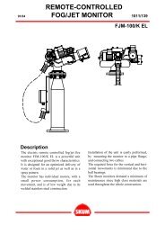
LEVEL MONITOR CONSOLE UP TO 12 TANKSALPHANUMERIC LEVEL MONITOR CONSOLEGeneral characteristics of Console :<strong>Level</strong> & Interstitial Monitor series monitoring exchange suitable to checksimultaneously up to 12 magnetostrictive level sensors and 12 interstitialsensors. Possibility of integration in the Software Station <strong>Management</strong>.Technical characteristics of console :Microprocessor electronics 16 bit flash technology 16MHzn ° 4 alarms to programmable relaisOptic signaller and acoustic hornsNr. 4 analogical inputs 4 - 20 m A , 2 wires technologyNr. 4 digital inputs from external sensors(overfilling, min. level switch, interstitial sensor, etc.)n ° 1 serial port RS485 for sensors bus inputn ° 1 s e r i a l p o r t R S 2 3 2Power supply: 9 ÷ 30 VDC / 220VacAluminium case with integrated 5 key keyboardEasy and reliable programming of mm / liters conversionchart up to 250 linearization pointsDynamic generation of tank strapping table by SmartTrackset up software or alternatively using a flow rate counterj o i n e d t o o u r SmartCal Software.Back- lighted alphanumeric display 4 lines 80 charactershigh visibility with simultaneously visualization of:CONSOLE LEVEL MONITOR UP TO 28 TANKS- product level in 0,1mm- r e a l v o l u m e i n litres- compensated volume at 15°C in litres- water detection- Product average temperature- U l l a g e ( empty part of the tank )- Alarm signals, unitUp to 12 channels version data ’s are shown alternatively.The level monitor gives electrical supply directly to the level s e n s o r .ECComplianceCONSOLE LEVEL MONITOR UP TO 12 TANKSOptions / Accessories:LocalprinterSingle and double channel version without displaySINGLE AND DOUBLE VERSIONIndustrial Modem GSM / GPRSWirelesscommunicationLEVEL MONITOR CONSOLE UP TO 12 TANKS
TOP LEVEL TOUCH SCREEN CONSOLE UP TO 32 TANKSFEATURES:C P U b o a r d a 4 0 0 M H z 2 5 6 M B S D R A MTFT Touch Screen 7 ” display 1024x768 up to 32 tanksBlind version: no visualization displayP r e - installed Smartrack softwareData Logger for data storageTank leakage controlPage and active icon selection with Touch/mouse/keyboardVisualizationof:- Product level in mm- Volume in litres- Compensated volume at 15 °C in liters- Liquid average temperature- Temperature profile- Empty volume in liters ( U l l a g e )- Graphic indication of the tank status- Alarm messages, measure unit, probes diagnosticLinearization with unlimited points for the strapping tableI / O:- N° 4 s e r i a l p o r t R S 2 3 2- N° 1 serial port PS2 for mouse and keyboard- N° 1 U S B p o r t- VGA output for an external monitor- Ethernet Interface for Internet / Intranet- P o w e r s u p p l y 2 2 0 V a cProbesdiagnosticTele- diagnostic and tele- maintenance via Internet / GSMCEMarkOperating temperature: - 2 5°C +50°CStorage temperature: - 2 5°C +80°CVibration endurance: 2Grms w/CFCase dimensions:metallic painted box 270 x 270 x 90 mmCompletewith:Serial converter RS232/RS485N° 4 a l a r m r e l è output NO 250Vac 1ADirect power supply to the probesOptional Interface card:RS485 serial port field busN° 4 a n a l o g inputs 4 - 2 0 m A two wires technologyN° 4 SPDT 250 Vac 1A programmable alarm relay outputsN° 4 digital inputs from external sensorsORDERING CODEBASE CODEI / OA 24VdcB 220VacPCT - T o p L e v e l v e r s i o nEXAMPLE:POWER SUPPLYLOCAL PRINTERGSM MODEMG GSM integrated moduleP integratedprinter0I+0R without I/O4I+4R 0 4 d i g i t a l / analog i n p u t s 0 4 relais o u t p u t8I+8R 0 8 d i g i t a l / analog i n p u t s 0 8 relais o u t p u t16I+16R 16 digital/analog inputs 16 r e l a i s o u t p u t32I+32R 32 digital/analog inputs 32 r e l a i s o u t p u tPCT 4I+4R B P GOption:Remote Graphical PrinterLocalPrinterTOP LEVEL TOUCH SCREEN CONSOLE UP TO 32 TANKS
INTERSTITIAL AND PRODUCTDISCRIMINATOR SENSORINTERSTITIAL AND PRODUCTDISCRIMINATOR SENSORGeneral CharacteristicsIt senses and signals the presence of liquid into the interstitial oftanks with double walls and discriminates between water and diese loil or between water and gasoline. The system is also able to car r yout one quantitative evaluation of the level of filling of the interstitial.The device is made up of one electronic card placed inside of th ec a s e a n d o f t h e t h r e a d e d s e n s o r t h a t c a n b e e a s i l y i n s e r t e d b e t we e nthe two layers of the tank through one of the scheduled accessesp l a c e d o n t o p o f t h e t a n k . R e m o t e d i a g n o s t i c o f t h e s e n s o r a n dpossibility to re -calibrating according to the new operatingenvironmental conditions. Presetting for possible interface with a nexternal sensor of pressure.Technical characteristics of the sensor :MicroprocessorElectronics12Vdc supply provided directly from the consoleN° 1 serial port RS485 for connection with the bus fieldN° 1 a n a l o g u e f o r t h e p r e s s u r e s e n s o rATEX Certification for combined execution of both intrinsic securityand increased security for installation in zone 0.Hydrocarbons-r e s i s t a n t t h r e a d e d S e n s o rDie -c a s t a l u m i n i u m c a s e p r o t e c t i o n s t a n d a r d I P 6 8E CC o m p l i a n c eGeneral characteristics of console :<strong>Level</strong> & Interstitial monitor series monitoring exchange suitable t ocheck simultaneously up to 12 magnetostrictive l e v e l s e n s o r s a n d 1 2interstitial sensors. Possibility of integration in the Software S t a t i o nM a n a g e m e n t .Technical characteristics of console:MicroprocessorelectronicsB a c k -lighted alphanumeric display 4 lines 80 charactersn° 4 a l a r m s t o p r o g r a m m a b l e relaisOptic signaller and acoustic hornsn° 1 serial port RS485 for sensors bus inputn° 1 s e r i a l p o r t R S 2 3 2Power supply: 9 ÷ 3 0 V D C / 2 2 0 V a cDirect supply to the sensors 12DdcA l u m i n i u m c a s e w i t h i n t e g r a t e d 5 k e y k e y b o a r dE CC o m p l i a n c e1) SENSOR 2) FEEDING 3) PCB 4) Or-ring5) 6)CABLE GLAND 7)RESIN 8)CASE9)COVERO P T I O N S / A C C E S S O R I E S :Localprinter
QUALITY ASSURANCEUNI EN ISO 9001:2000START italiana srlvia Napoli, 29/A20030 Bovisio MasciagoTel.+390362594361Fax+390362596171info@startitaliana.ittwww.startitaliana.it