Bid Documents (Specs Pkg) - Wakulla County
Bid Documents (Specs Pkg) - Wakulla County
Bid Documents (Specs Pkg) - Wakulla County

Create successful ePaper yourself
Turn your PDF publications into a flip-book with our unique Google optimized e-Paper software.
OCHLOCKONEE BAY TRAIL – PHASE IV FDIP PROJECT # 414032-1-58-01FEDERAL PROJECT # S E – 8886 (004)TABLE OF CONTENTSBIDDING AND CONTRACT DOCUMENTS00010 Statement of Work00050 Special Prequalification Requirements00100 Instructions to bidders00400 <strong>Bid</strong> Proposal00410 <strong>Bid</strong> Schedule00420 <strong>Bid</strong>ders Qualification Statement00500 Construction Agreement00610 Performance Bond00620 Payment Bond00700 General Conditions00710 Insurance Requirements00850 Release and Affidavit00860 Conflict of Interest Disclosure Statement00870 Drug Free Workplace Certification00880 Ethics Clause00890 Non-Collusion Affidavit00900 Change OrderFDOT SPECIAL PROVISIONSFDOT SUPPLEMENTAL SPECIFICATIONSFDOT LOCAL AGENCY PROGRAM/FEDERAL-AID CONTRACT REQUIREMENTSPERMITSTABLE OF CONTENTS PAGE 1 of 1
OCHLOCKONEE BAY TRAIL – PHASE IV FDIP PROJECT # 414032-1-58-01FEDERAL PROJECT # S E – 8886 (004)SECTION 00010 – STATEMENT OF WORKOchlockonee Bay Trail-Phase IV is a 4.8 mile Multi-Use Trail situated within <strong>County</strong> Road 372Right-of-Way in <strong>Wakulla</strong> <strong>County</strong> Florida. The Multi-Use Trail will consist of grading,drainage, paving and other miscellaneous construction associated with this project type.SECTION 00010 - STATEMENT OF WORK PAGE 1 OF 1
OCHLOCKONEE BAY TRAIL – PHASE IV FDIP PROJECT # 414032-1-58-01FEDERAL PROJECT # S E – 8886 (004)1. SPECIAL PREQUALIFICATION REQUIREMENTS. All contractors submitting bids arerequired to meet the special prequalification requirements for this project prior to submitting bids.Previous prequalification will not be considered to meet this requirement.This special project-specific process will prequalify potential bidders whose bids will be consideredfor award based on the items listed below. It is the prospective bidder’s responsibility to submitdocumentation for those items listed below, to the <strong>Wakulla</strong> <strong>County</strong> Purchasing Office, by 10:00 A.M.on May 31, 2012. <strong>Wakulla</strong> <strong>County</strong> may request any other documents it may deem necessary. Anyadditional documents so requested shall be submitted to the <strong>Wakulla</strong> <strong>County</strong> Purchasing Office at thetime and date designated in the request. Once the following documents are submitted, the <strong>County</strong> willdetermine if the prospective bidder is prequalified to submit a bid for the project.a) COVER LETTER. The cover letter provided by the prospective bidder with theprequalification information must include the name and contact information for an individualthat the <strong>County</strong> may contact to obtain additional information, if needed.b) FLORIDA DEPARTMENT OF TRANSPORTATION (FDOT) PREQUALIFICATIONS.The prospective bidder shall provide documentation from FDOT that states the work classesin which the prospective bidder is currently prequalified. The prospective bidder shallperform with his own organization, normal work amounting to not less than fifty percent(50%) of the total budget estimate of the total cost of the normal work.The prospective bidder shall provide their current FDOT Maintenance of Traffic (MOT)Certification documentation to the <strong>County</strong>. For this project, the MOT Certification willaccount for 6% of the normal work percentage.Therefore, not less than 44% of the normal work percentage will be combination of the workclasses listed below.Work ClassNormal Work PercentageGrading 26%Flexible Paving 21%Hot Plant-Mixed Bitumen Courses 9%Drainage 5%*Any Work Classes the prospective bidder is not prequalified in shall be performed asubcontractor that has the FDOT prequalification for the specific Work Class associated withthe work the subcontractor will be performing.Any subcontractor FDOT prequalification documentation shall be submitted with thecomplete bid proposal on June 15, 2012 and is not required to be submitted with theprequalification submittal on May 31, 2012.c) SECTION 00420 – BIDDERS QUALIFICATION STATEMENT. The prospective biddershall submit a completed Section 00420 of the Contract <strong>Documents</strong>. If a prospective bidder isprequalified to submit a bid, a completed Section 00420 shall be included in the biddocuments.d) DISADVANTAGED BUSINESS ENTERPRISE (DBE) PROGRAM. The prospectivebidder shall provide documentation of their approved Disadvantage Business Enterprise(DBE) Affirmative Action Program Plan filed with the FDOT’s Equal Opportunity Office. Ifa prospective bidder has only submitted a plan for approval, the prospective bidder will notbe prequalified to submit a bid.SECTION 00050 – SPECIAL PREQUALIFICATION REQUIREMENTS PAGE 1 OF 2
OCHLOCKONEE BAY TRAIL – PHASE IV FDIP PROJECT # 414032-1-58-01FEDERAL PROJECT # S E – 8886 (004)e) BID OPPORTUNITY LIST. The prospective bidder shall submit a completed <strong>Bid</strong>Opportunity List as provided in the Contract <strong>Documents</strong> Section FDOT Local AgencyProgram/Federal-Aid Contract Requirements on Pages 53 and 54. If a prospective bidder isprequalified to submit a bid, a completed <strong>Bid</strong> Opportunity List shall be included in the biddocuments.f) LOCAL AGENCY PROGRAM/FEDERAL-AID CERTIFICATION. The prospectivebidder shall submit a completed Local Agency Program/Federal-Aid Certification asprovided in the Contract <strong>Documents</strong> Section FDOT Local Agency Program/Federal-AidContract Requirements on Pages 19-21. If a prospective bidder is prequalified to submit abid, a completed Local Agency Program/Federal-Aid Certification shall be included in thebid documents.Utilization: For this FDOT assisted contract, the local agency has adopted the FDOT DBEProgram goal. The FDOT began its race neutral DBE program on January 1, 2000 and has anoverall 8.18% goal it must achieve. While the utilization is not mandatory in order to beawarded the contract, continuing utilization of DBE firms on contracts supports the successof Florida’s Voluntary DBE Program, and supports contractor’s Equal EmploymentOpportunity and DBE Affirmative Action Programs.Clarification: The 8.18% is a goal and not a requirement. It is highly encouraged to tryto achieve this goal. A Contractor will not be considered non-responsive if this goal isnot met.g) ANTICIPATED DBE PARTICIPATION STATEMENT (‘ADBEPS’) LOCAL AGENCYPROGRAM. The prospective bidder shall submit a completed Anticipated DBE ParticipationStatement as provided in the Contract <strong>Documents</strong> Section FDOT Local AgencyProgram/Federal-Aid Contract Requirements on Page 52. If a prospective bidder isprequalified to submit a bid, a completed Anticipated DBE Participation Statement shall beincluded in the bid documents.<strong>Wakulla</strong> <strong>County</strong> will review each pre-qualification submittal. The following conditions will apply:a) <strong>Wakulla</strong> <strong>County</strong> shall be the sole judge as to the acceptability of the prequalificationsubmittal on this project.b) The <strong>County</strong>, in its sole discretion, may reject a bid for failure to demonstrate acceptableperformance, experience, expertise and/or FDOT prequalification.c) Any proposals submitted by a non prequalified bidder shall be returned unopened, and ifinadvertently opened, shall not be considered.d) A list of prequalified bidders will be posted on the <strong>County</strong>’s website on June 4, 2012.For additional information contact George Roland, P.E., Kimley-Horn and Associates, Inc. at (904) 828-3900. Prequalification submittal should be sent to:<strong>Wakulla</strong> <strong>County</strong> Board of <strong>County</strong> Commissioners Purchasing OfficeP.O. Box 1263 (32326)3093 Crawfordville HighwayCrawfordville, Florida 32327(850) 926-9500SECTION 00050 – SPECIAL PREQUALIFICATION REQUIREMENTS PAGE 2 OF 2
OCHLOCKONEE BAY TRAIL – PHASE IV FDIP PROJECT # 414032-1-58-01FEDERAL PROJECT #S E – 8886 (004)SECTION 00100 – INSTRUCTIONS TO BIDDERSSection 1. Definitions.1.1 The term "COUNTY" used herein refers to WAKULLA COUNTY,FLORIDA, or its duly authorized representative.1.2 The term "<strong>Bid</strong>der" used herein means one who submits a bid directly to theCOUNTY in response to this solicitation.1.3 The term "Successful <strong>Bid</strong>der" means the lowest qualified, responsible andresponsive <strong>Bid</strong>der who is awarded the contract by the COUNTY, on the basisof the COUNTY's evaluation.1.4 The term "<strong>Bid</strong>ding <strong>Documents</strong>" includes the Legal Advertisement, theseInstructions to <strong>Bid</strong>ders, the <strong>Bid</strong> Schedule and the Contract <strong>Documents</strong> asdefined in the Agreement.1.5 The term "<strong>Bid</strong>" shall mean a completed <strong>Bid</strong> Proposal (Section 00400), <strong>Bid</strong>Schedule (Section 00410), and <strong>Bid</strong>der’s Qualifications Statement (Section00420), bound in the <strong>Bid</strong>ding <strong>Documents</strong>, properly signed, providing theCOUNTY a proposed cost for providing the services required in the <strong>Bid</strong>ding<strong>Documents</strong>.1.6 The term "Work" includes all work required in connection with the Projectspecified in the Legal Advertisement for this solicitation as set forth in the<strong>Bid</strong>ding <strong>Documents</strong> for this Project.1.7 The term “Contractor” used herein refers to the individual, firm, joint ventureor company contracting with <strong>Wakulla</strong> <strong>County</strong>.Section 2.Preparation of <strong>Bid</strong>s2.1 The <strong>Bid</strong>s must be submitted on the standard form herein furnished by theCOUNTY (pages 00410-1 to 00410-2 as bound in these <strong>Bid</strong>ding <strong>Documents</strong>). The <strong>Bid</strong>dershall complete the <strong>Bid</strong> in ink or by type, and the original <strong>Bid</strong> shall be manually signed by the<strong>Bid</strong>der. An original and three (3) copies of the <strong>Bid</strong> fastened by clip (please, NO staples)must be received by the COUNTY no later than Friday, June 15, 2012 at 10:00 a.m. localtime in the offices of the COUNTY in Crawfordville, Florida. The <strong>Bid</strong> may be rejected if itcontains any omissions, alteration of form, conditional bid or irregularities of any kind. <strong>Bid</strong>sfrom entities not prequalified shall be rejected and returned unopened. <strong>Bid</strong>s must besubmitted in sealed envelopes, marked with the <strong>Bid</strong> Number, Project Name, <strong>Bid</strong> OpeningDate and Time, and shall be addressed to:SECTION 00100 - INSTRUCTIONS TO BIDDERS PAGE 1 OF 11
OCHLOCKONEE BAY TRAIL – PHASE IV FDIP PROJECT # 414032-1-58-01FEDERAL PROJECT #S E – 8886 (004)<strong>Wakulla</strong> <strong>County</strong> Board of <strong>County</strong> Commissioners Purchasing OfficeP.O. Box 1263 (32326)3093 Crawfordville HighwayCrawfordville, Florida 32327(850) 926-9500If forwarded by mail, the sealed envelope containing the <strong>Bid</strong> must be enclosed in anothersealed envelope addressed as above. <strong>Bid</strong>s received after the time specified for bid openingwill be returned to the <strong>Bid</strong>der unopened and shall not be considered.Section 3.<strong>Bid</strong> Deposit Requirements3.1 No <strong>Bid</strong> shall be considered or accepted unless at the time of <strong>Bid</strong> filing thesame shall be accompanied by a cashier's check, a certified check payable to COUNTY onsome bank or trust company located in the State of Florida insured by the Federal DepositInsurance Corporation, or bid bond, in an amount not less than 5% of the <strong>Bid</strong> issued by aSurety authorized to issue such bonds in the State of Florida (collectively referred to hereinas the "<strong>Bid</strong> Deposit"). The <strong>Bid</strong> Deposit shall be retained by COUNTY as liquidateddamages if the successful <strong>Bid</strong>der fails to execute and deliver to COUNTY the constructionagreement, or fails to deliver the required performance and payment bonds or certificates ofinsurance, all within ten (10) calendar days after receipt of the Notice of Award. TheAttorney-in-fact who executes this bond on behalf of the Surety must attach a notarized copyof the Power of Attorney as evidence of its authority to bind the Surety. Where laws orregulations require certification by a resident agent shall also be provided. <strong>Bid</strong> Deposits ofthe three (3) lowest <strong>Bid</strong>ders shall be held until the Agreement has been executed by theSuccessful <strong>Bid</strong>der and same has been delivered to COUNTY together with the requiredbonds and insurances, after which all three (3) <strong>Bid</strong> Deposits shall be returned to therespective <strong>Bid</strong>ders. All other <strong>Bid</strong> Deposits shall be released within ten (10) working days ofthe <strong>Bid</strong> Opening. No <strong>Bid</strong> shall be withdrawn within ninety (90) days after the publicopening thereof. If a <strong>Bid</strong> is not accepted within ninety (90) days after the public opening, itshall be deemed rejected and the <strong>Bid</strong> Deposit shall be returned to <strong>Bid</strong>der as provided herein.3.2 The Successful <strong>Bid</strong>der shall execute three (3) copies of the Agreement anddeliver same to COUNTY within the time period noted above. The COUNTY shall executeall three (3) copies and return two fully executed copies of the Agreement to Successful<strong>Bid</strong>der within thirty (30) working days after receipt of the executed Agreement fromSuccessful <strong>Bid</strong>der unless any governmental agency having funding control over the Projectrequires additional time, in which event the COUNTY shall have such additional time toexecute the Agreement as may be reasonably necessary.Section 4.Right to Reject Proposals4.1 COUNTY reserves the right to reject any and all <strong>Bid</strong>s or to waiveinformalities and negotiate with the apparent lowest, responsive, qualified and responsibleSECTION 00100 - INSTRUCTIONS TO BIDDERS PAGE 2 OF 11
OCHLOCKONEE BAY TRAIL – PHASE IV FDIP PROJECT # 414032-1-58-01FEDERAL PROJECT #S E – 8886 (004)<strong>Bid</strong>der. Further, COUNTY reserves the right to withdraw this solicitation at anytime prior tofinal award and execution of the contract. COUNTY is not liable for any costs incurred by<strong>Bid</strong>der prior to issuance of the executed Agreement as set forth in Section 3.2 hereof.4.2 COUNTY reserves the right to formally amend and/or clarify therequirements of the <strong>Bid</strong> Specifications where it deems necessary. Any suchaddendum/clarification shall be in writing and shall be distributed to all parties who receivethe original bid specification and are eligible for consideration prior to the deadline forsubmission of proposals.Section 5.Signing of <strong>Bid</strong>s5.1 <strong>Bid</strong>s submitted by a corporation must be executed in the corporate name bythe president or a vice president, and a corporate seal must be affixed andattested to by the secretary or assistant secretary of the corporation. Thecorporate address and state of incorporation must be shown below thesignature.5.2 <strong>Bid</strong> proposals by a partnership must be executed in the partnership name andsigned by a general partner whose title must appear under the signature andthe official address of the partnership must be shown below said signature.5.3 If <strong>Bid</strong>der is an individual, his signature shall be inscribed.5.4 If signature is by an agent or other than an officer of corporation or generalpartner of partnership, a properly notarized power of attorney must besubmitted with the <strong>Bid</strong>.5.5 All <strong>Bid</strong>s shall have names typed or printed below all signatures.5.6 All <strong>Bid</strong>s shall state the <strong>Bid</strong>der's contractor and subcontractor’s licensenumber.5.7 Failure to follow the provisions of this section shall be grounds for rejectingthe <strong>Bid</strong> as irregular or unauthorized.Section 6.Withdrawal of ProposalsAny <strong>Bid</strong> may be withdrawn at any time prior to the hour fixed in the Legal Advertisementfor the opening of <strong>Bid</strong>s, provided that the withdrawal is requested in writing, properlyexecuted by the <strong>Bid</strong>der and received by COUNTY prior to <strong>Bid</strong> Opening. The withdrawal ofa <strong>Bid</strong> will not prejudice the right of a <strong>Bid</strong>der to file a new <strong>Bid</strong> prior to the time specified for<strong>Bid</strong> opening.SECTION 00100 - INSTRUCTIONS TO BIDDERS PAGE 3 OF 11
OCHLOCKONEE BAY TRAIL – PHASE IV FDIP PROJECT # 414032-1-58-01FEDERAL PROJECT #S E – 8886 (004)Section 7.Late <strong>Bid</strong>s<strong>Bid</strong>s received after the scheduled receipt time will not be accepted and shall be returnedunopened to the sender.Section 8.Interpretation of Contract <strong>Documents</strong>8.1 A Cone of Silence will be in effect for this invitation for bids beginning withthe advertisement date, May 17, 2012. The prospective bidder shall not have anycommunication with any <strong>County</strong> personnel. No interpretation of the meaning of the plans,specifications or other <strong>Bid</strong>ding <strong>Documents</strong> shall be made to a <strong>Bid</strong>der orally. Any such oralor other interpretations or clarifications shall be without legal affect. All requests forinterpretations or clarifications shall be in writing, addressed to the COUNTY, to be givenconsideration. All such requests for interpretations or clarification must be receivedbefore/on June 11, 2012. Any and all such interpretations and supplemental instructionsshall be in the form of written addendum which, if issued, shall be posted on the <strong>County</strong>’swebsite for such purposes no later than three (3) working days prior to the date fixed for theopening of <strong>Bid</strong>s. Such written addenda shall be binding on <strong>Bid</strong>der and shall become a partof the <strong>Bid</strong>ding <strong>Documents</strong>.8.2 It shall be the responsibility of each <strong>Bid</strong>der to ascertain, prior to submittinghis <strong>Bid</strong> that he has received all addenda issued and he shall acknowledgesame in his <strong>Bid</strong>.Section 9.Examination of Site and Contract <strong>Documents</strong>9.1 By executing and submitting a <strong>Bid</strong>, each <strong>Bid</strong>der certifies that the submitterhas:a. Examined all <strong>Bid</strong>ding <strong>Documents</strong> thoroughly;b. Visited the site to become familiar with local conditions that may in anymanner affect performance of the Work;c. Become familiar with all federal, state and local laws, ordinances, rules, andregulations affecting performance of the Work; andd. Correlated all of his observations with the requirements of <strong>Bid</strong>dingdocuments.No plea of ignorance of conditions or difficulties that may exist or conditions or difficultiesthat may be encountered in the execution of the Work pursuant to these <strong>Bid</strong>ding <strong>Documents</strong>SECTION 00100 - INSTRUCTIONS TO BIDDERS PAGE 4 OF 11
OCHLOCKONEE BAY TRAIL – PHASE IV FDIP PROJECT # 414032-1-58-01FEDERAL PROJECT #S E – 8886 (004)as a result of failure to make the necessary examinations and investigations shall be acceptedas an excuse for any failure or omission on the part of the Successful <strong>Bid</strong>der, nor shall theybe accepted as a basis for any claims whatsoever for extra compensation or for an extensionof time.9.2 The COUNTY will make copies of surveys and reports performed inconjunction with this Project available to any <strong>Bid</strong>der requesting them at cost; provided,however, the COUNTY does not warrant or represent to any <strong>Bid</strong>der either the completenessor accuracy of any such surveys and reports. Before submitting his <strong>Bid</strong>, each <strong>Bid</strong>der shall, athis own expense, make such additional surveys and investigations as may be necessary todetermine his <strong>Bid</strong> price for the performance of the Work within the terms of the <strong>Bid</strong>ding<strong>Documents</strong>.Section 10.Material RequirementsIt is the intention of these <strong>Bid</strong>ding <strong>Documents</strong> to identify standard materials. When space isprovided on the <strong>Bid</strong> Schedule, <strong>Bid</strong>ders shall specify the materials which they propose to usein the Project. The COUNTY may declare any <strong>Bid</strong> non-responsive or irregular if suchmaterials are not specifically named by <strong>Bid</strong>der.Section 11.<strong>Bid</strong> QuantitiesQuantities given in the <strong>Bid</strong> Schedule, while estimated from the best information available,are approximate only. Payment for unit price items shall be based on the actual number ofunits installed for the Work. <strong>Bid</strong>s shall be compared on the basis of number of units stated inthe <strong>Bid</strong> Schedule as set forth in the <strong>Bid</strong>ding <strong>Documents</strong>. Said unit prices shall be multipliedby the bid quantities for the total <strong>Bid</strong> price. Any <strong>Bid</strong> not conforming to this requirementmay be rejected. Special attention to all <strong>Bid</strong>ders is called to this provision, for shouldconditions make it necessary or prudent to revise the unit quantities, the unit prices will befixed for such increased or decreased quantities. Compensation for such additive orsubtractive changes in the quantities shall be limited to the unit prices in the <strong>Bid</strong>.Section 12.Award of Contract and Right to ProtestAward of contract shall be made to the lowest, responsive, qualified and responsible <strong>Bid</strong>derdetermined on the basis of the entire <strong>Bid</strong> and the COUNTY's investigations of the <strong>Bid</strong>der.When the contract is awarded by COUNTY, such award shall be evidenced by a writtendocument "Notice of Award," signed by the authorized representative of COUNTY anddelivered to the intended awardee by certified mail or other express delivery service, and acopy also provided to each bidder for the project.Award of Contract will be made by the COUNTY Board in public session. Awardrecommendations will be posted outside the offices of the COUNTY at its Crawfordvilleaddress. Any <strong>Bid</strong>der who desires to formally protest shall follow the procedure outline in<strong>Wakulla</strong> <strong>County</strong>, Part II - Code of Ordinances, Chapter 2- Administration, Article 6 –Purchasing, Section 2.257 (16) – Competitive purchases/solicitations.SECTION 00100 - INSTRUCTIONS TO BIDDERS PAGE 5 OF 11
OCHLOCKONEE BAY TRAIL – PHASE IV FDIP PROJECT # 414032-1-58-01FEDERAL PROJECT #S E – 8886 (004)For <strong>Bid</strong>ders who may wish to receive copies of <strong>Bid</strong>s after the <strong>Bid</strong> opening, the COUNTYreserves the right to recover all costs associated with the printing and distribution of suchcopies.Section 13.Sales TaxThe COUNTY is a political subdivision of the State of Florida and is exempt from thepayment of Florida sales tax. Corporations, Individuals and other entities are impacted byChapter 212, Florida Statutes according to the type of service, sale of commodity or othercontractual arrangement to be made with the COUNTY. By submittal of a properly executedresponse to a procurement request from the COUNTY, the <strong>Bid</strong>der is acknowledging that heis aware of his statutory responsibilities for sales tax under Chapter 212, Florida Statutes.The COUNTY is also exempt from most Federal excise taxes. By submittal of a properlyexecuted response to a procurement request from the COUNTY, the <strong>Bid</strong>der isacknowledging that he is aware of his responsibilities for Federal excise taxes.Section 14.Exclusion of <strong>County</strong> Permits in <strong>Bid</strong> Prices14.1 To ensure compliance with Section 218.80, F.S., otherwise known as "ThePublic <strong>Bid</strong> Disclosure Act", the COUNTY will pay for all local <strong>County</strong> permits and fees,including license fees, permit fees, impact fees or inspection fees applicable to this work.<strong>Bid</strong>ders shall not include these permit/fee amounts in their bid offer. However, the successfulbidder shall retain the responsibility to initiate and complete all necessary and appropriateactions to obtain the required permits other than payment for the items identified in thissection.14.2 The successful <strong>Bid</strong>der shall be responsible for procuring and paying for allnecessary permits not issued by the local Counties pursuant to theprosecution of the work.Section 15.Public Entity CrimesSection 287.133, Florida Statutes, provides:A person or affiliate who has been placed on the convicted vendor listfollowing a conviction for a public entity crime may not submit a bid on acontract to provide any goods or services tot a public entity, may not submita bid on a contract with a public entity for the construction or repair of apublic building or public work, may not submit bids on leases of realproperty to a public entity, may not be awarded or perform work as acontractor, subcontractor or consultant under a contract with any publicentity, and may not transact business with any public entity in excess of thethreshold amount provided in Section 287.017 Florida Statutes, forSECTION 00100 - INSTRUCTIONS TO BIDDERS PAGE 6 OF 11
OCHLOCKONEE BAY TRAIL – PHASE IV FDIP PROJECT # 414032-1-58-01FEDERAL PROJECT #S E – 8886 (004)CATEGORY TWO for a period of 36 months from the date of being placedon the convicted vendor list.<strong>Bid</strong>der shall complete and return the public entity crimes affidavit included in the <strong>Bid</strong>ding<strong>Documents</strong>.SECTION 00100 - INSTRUCTIONS TO BIDDERS PAGE 7 OF 11
OCHLOCKONEE BAY TRAIL – PHASE IV FDIP PROJECT # 414032-1-58-01FEDERAL PROJECT #S E – 8886 (004)SWORN STATEMENT UNDER SECTION 287.133(3)(a),FLORIDA STATUTES, ON PUBLIC ENTITY CRIMESTHIS FORM MUST BE SIGNED AND SWORN TO IN THE PRESENCE OF A NOTARYPUBLIC OR OTHER OFFICIAL AUTHORIZED TO ADMINISTER OATHS.1. This sworn statement is submitted to <strong>Wakulla</strong> <strong>County</strong> Board of <strong>County</strong>CommissionersBy_____________________________________________________________________________[print individual's name and title]for_____________________________________________________________________________[print name of entity submitting sworn statement]whose business address is:________________________________________________________________________________________________________________________________________________and (if applicable) its Federal Employer Identification Number (FEIN) is ._____________________ (If the entity has no FEIN, include the Social SecurityNumber of the individual signing this sworn statement).____________________________________________________________________ .2. I understand that a "public entity crime" as defined in Paragraph 287.133(1)(g),Florida Statutes, means a violation of any state or federal law by a person withrespect to and directly related to the transaction of business with any public entityor with an agency or political subdivision of any other state or of the United States,including, but not limited to, any bid or contract for goods or services to beprovided to any public entity or an agency or political subdivision of any other state or ofthe United States and involving antitrust, fraud, theft, bribery, collusion, racketeering,conspiracy, or material misrepresentation.SECTION 00100 - INSTRUCTIONS TO BIDDERS PAGE 8 OF 11
OCHLOCKONEE BAY TRAIL – PHASE IV FDIP PROJECT # 414032-1-58-01FEDERAL PROJECT #S E – 8886 (004)3. I understand that "convicted" or "conviction" as defined in Paragraph287.133(1)(b), Florida statutes, means a finding of guilt or a conviction of a publicentity crime, with or without an adjudication of guilt, in any federal or state trial courtof record relating to charges brought by indictment or information after July 1, 1989,as a result of a jury verdict, non-jury trial, or entry of a plea of guilty or nolo contendere.4. I understand that an "affiliate" as defined in Paragraph 287.133(1)(a), FloridaStatutes, means:ora. A predecessor or successor of a person convicted of a public entity crime:b. An entity under the control of any natural person who is active in themanagement of the entity and who has been convicted of a public entitycrime. The term "affiliate" includes those officers, directors, executives,partners, shareholders, employees, members, and agents who are activein the management of an affiliate. The ownership by one person of sharesconstituting a controlling interest in another person, or a pooling ofequipment or income among persons when not for fair market valueunder an arm's length agreement, shall be a prima facie case that oneperson controls another person. A person who knowingly enters into ajoint venture with a person who has been convicted of a public entitycrime in Florida during the preceding 36 months shall be considered anaffiliate.5. I understand that a "person" as defined in Paragraph 287.133(1)(e), FloridaStatutes, means any natural person or entity organized under the laws of anystate or of the United States with the legal power to enter into a binding contractand which bids or applies to bid on contracts for the provision of goods orservices let by a public entity, or which otherwise transacts or applies to transactbusiness with a public entity. The term "person" includes those officers, directors,executives, partners, shareholders, employees, members, and agents who areactive in management of an entity.6. Based on information and belief, the statement which I have marked below istrue in relation to the entity submitting this sworn statement. [Indicate whichstatement applies.]______ Neither the entity submitting this sworn statement, nor any of its officers,directors, executives, partners, shareholders, employees, members, orSECTION 00100 - INSTRUCTIONS TO BIDDERS PAGE 9 OF 11
OCHLOCKONEE BAY TRAIL – PHASE IV FDIP PROJECT # 414032-1-58-01FEDERAL PROJECT #S E – 8886 (004)agents who are active in management of the entity, nor any affiliate of theentity has been charged with and convicted of a public entity crimesubsequent to July 1, 1989.______ The entity submitting this sworn statement, or one or more of its officers,directors, executives, partners, shareholders, employees, members, oragents who are active in management of the entity, or an affiliate of theentity has been charged with and convicted of a public entity crimesubsequent to July 1, 1989.______ The entity submitting this sworn statement, or one or more of its officers,directors, executives, partners, shareholders, employees, members, oragents who are active in management of the entity, or an affiliate of theentity has been charged with and convicted of a public entity crimesubsequent to July 1, 1989. However there has been a subsequentproceeding before a hearing a Hearing Officer of the State of Florida,Division of Administrative Hearings and the Final Order entered by theHearing Officer determined that it was not in the public interest to placethe entity submitting this sworn statement on the convicted contractorlist. [Attach a copy of the final order.]I UNDERSTAND THAT THE SUBMISSION OF THIS FORM TO THE CONTRACTING OFFICERFOR THE PUBLIC ENTITY IDENTIFIED IN PARAGRAPH 1 (ONE) ABOVE IS FOR THATPUBLIC ENTITY ONLY AND, THAT THIS FORM IS VALID THROUGH DECEMBER 31 OF THECALENDAR YEAR IN WHICH IT IS FILED. I ALSO UNDERSTAND THAT I AM REQUIRED TOINFORM THE PUBLIC ENTITY PRIOR TO ENTERING INTO A CONTRACT IN EXCESS OF THETHRESHOLD AMOUNT PROVIDED IN SECTION 287.017, FLORIDA STATUTES FORCATEGORY TWO OF ANY CHANGE IN THE INFORMATION CONTAINED IN THIS FORM._____________________________________(Signature)Sworn to and subscribed before me this ______ day of, 200_ .Personally known _____________ OR Produced identification_________________________________(Type of identification)______________________________________SECTION 00100 - INSTRUCTIONS TO BIDDERS PAGE 10 OF 11
OCHLOCKONEE BAY TRAIL – PHASE IV FDIP PROJECT # 414032-1-58-01FEDERAL PROJECT #S E – 8886 (004)NOTARY PUBLICNotary Public - State of_________________________My commission expires:______________________________________________________________________Printed, typed, or stamped commissionedname of notary publicSECTION 00100 - INSTRUCTIONS TO BIDDERS PAGE 11 OF 11
OCHLOCKONEE BAY TRAIL – PHASE IV FDIP PROJECT # 414032-1-58-01FEDERAL PROJECT # S E – 8886 (004)SECTION 00400 – BID PROPOSALBID PROPOSALWAKULLA COUNTY, FLORIDAFull Company Name of <strong>Bid</strong>der:____________________________________________________Main Business Address:__________________________________________________________(including city, state and zip)Place of Business:_______________________________________________________________(including city, state and zip)Business Telephone and Fax Numbers:______________________________________________Contact Name:_________________________________________________________________State Contractor's License#________________________________________________________To: BOARD OF COUNTY COMMISSIONERS OF WAKULLA COUNTY, FLORIDA(hereinafter called the "COUNTY")The undersigned, as <strong>Bid</strong>der declares that the only person or parties interested in this Proposal asprincipals are those named herein, that this Proposal is made without collusion with any otherperson, firm or corporation; that he has carefully examined the location of the proposed work, theproposed forms of Agreement and Bonds, and the Contract Drawings and Specifications, includingAddenda issued thereto and acknowledges receipt below:Contractor'sAddendum Number Date Issued Initials-------------- ----------- -------------------------- ----------- -------------------------- ----------- ------------<strong>Bid</strong>der proposes, and agrees if this Proposal is accepted, <strong>Bid</strong>der will contract with the COUNTY inthe form of the copy of the Agreement included in these Contract <strong>Documents</strong>, to provide allnecessary machinery, tools, apparatus and other means of construction, including utility andSECTION 00400 – BID PROPOSAL PAGE 1 of 5
OCHLOCKONEE BAY TRAIL – PHASE IV FDIP PROJECT # 414032-1-58-01FEDERAL PROJECT # S E – 8886 (004)transportation services necessary to do all the Work, and furnish all the materials and equipmentspecified or referred to in the Contract <strong>Documents</strong> in the manner and time herein prescribed andaccording to the requirements of the COUNTY as therein set forth, furnish the Contractor's Bondsand Insurance specified in the General Conditions of the Contract, and to do all other things requiredof the Contractor by the Contract <strong>Documents</strong>, and that he will take full payment the sums set forth inthe following <strong>Bid</strong> Schedule (Section 00410):MATERIAL MANUFACTURERSThe <strong>Bid</strong>der is required to state below, material manufacturers he proposes to utilize on this project.No change will be allowed after submittal of <strong>Bid</strong>. If substitute material proposed and listed below isnot approved by Engineer, <strong>Bid</strong>der shall furnish the manufacturer named in the specification.Acceptance of this <strong>Bid</strong> does not constitute acceptance of material proposed on this list. THIS LISTMUST BE COMPLETED OR BID MAY BE DEEMED NON-RESPONSIVE.MATERIALMANUFACTURER1. __________________ _______________________2. __________________ _______________________3. __________________ _______________________4. __________________ _______________________5. __________________ _______________________6. __________________ _______________________Dated _____________<strong>Bid</strong>der _____________________________By _____________________________LIST OF SUBCONTRACTORSThe undersigned states that the following is a full and complete list of the proposed subcontractorson this Project and the class of work to be performed by each, and that such list will not be added tonor altered without written consent of the owner through the Engineer.Subcontractorand addressClass of Workto be performedSECTION 00400 – BID PROPOSAL PAGE 2 of 5
OCHLOCKONEE BAY TRAIL – PHASE IV FDIP PROJECT # 414032-1-58-01FEDERAL PROJECT # S E – 8886 (004)Dated _____________<strong>Bid</strong>der _____________________________By _____________________________BID REPRESENTATIONSUpon receipt of written notice of the conditional acceptance of this <strong>Bid</strong>, <strong>Bid</strong>der will execute theformal Contract attached within 10 calendar days and deliver the Surety Bond or Bonds andInsurance as required by the Contract <strong>Documents</strong>. The bid security attached in the sumof:____________________________________________________________________________dollars ($_____________) is to become the property of the COUNTY in the event the Contract,Insurance and Bonds are not executed within the time above set forth for the delay and additionalexpense to the COUNTY.If awarded a contract under this Proposal, the undersigned proposes to commence work at the sitewithin 5 calendar days from the commencement date established in the written Notice to Proceed.The undersigned further agrees to substantially complete all work covered by this Proposal within212 consecutive calendar days from and including the date stipulated in the written Notice toProceed and to be fully completed to the point of final acceptance by the COUNTY within 242consecutive calendar days from and including the date stipulated in the written Notice to Proceed.Respectfully SubmittedState of _____________)<strong>County</strong> of ____________)__________________________________________________, being first duly sworn on oathdeposes and says that the <strong>Bid</strong>der on the above Proposal is organized as indicated below and that allstatements herein made are made on behalf of such <strong>Bid</strong>der and that this deponent is authorized tomake them.__________________________________________________, also deposes and says that he hasexamined and carefully prepared his <strong>Bid</strong> Proposal from the Contract Drawings and Specificationsand has checked the same in detail before submitting this <strong>Bid</strong>; that the statements contained hereinare true and correct.SECTION 00400 – BID PROPOSAL PAGE 3 of 5
OCHLOCKONEE BAY TRAIL – PHASE IV FDIP PROJECT # 414032-1-58-01FEDERAL PROJECT # S E – 8886 (004)(a) CorporationThe <strong>Bid</strong>der is a corporation organized and existing under the laws of the State of____________________, which operates under the legal name of____________________________________, and the full names of its officers are as follows:President___________________________________Secretary___________________________________Treasurer___________________________________Manager_____________________________________and it (does) or (does not) have a corporate seal. The (name)__________________________________ is authorized to sign construction proposals and contractsfor the company by action of its Board of Directors taken _____________________________, acertified copy of which is hereto attached (strike out this last sentence if not applicable).(b) PartnershipThe <strong>Bid</strong>der is a co-partnership consisting of individual partners whose full names are as follows:___________________________________ ____________________________________________________________ ____________________________________________________________ ____________________________________________________________ ____________________________________________________________ _________________________The co-partnership does business under the legal name of:_____________________________________________(c) IndividualThe <strong>Bid</strong>der is an individual whose full name is _________________ _________________________,and if operating under a trade name, said trade name is: ___________________________________SECTION 00400 – BID PROPOSAL PAGE 4 of 5
OCHLOCKONEE BAY TRAIL – PHASE IV FDIP PROJECT # 414032-1-58-01FEDERAL PROJECT # S E – 8886 (004)Dated_______________ ______________________________legal entity____________________Witness____________________WitnessBy___________________________Name of <strong>Bid</strong>der (typed)______________________________Signature/Title[Corporate Seal]STATE OF _____________COUNTY OF ______________The foregoing instrument was acknowledged before me this______ day of _______________, ______, by _______________________, as____________________ of ____________________________________, a _______________corporation, on behalf of the corporation. He/she is personally known to me or has produced__________________________________________ as identification and did (did not) take an oath.My Commission Expires: _______________________________________(Signature of Notary)Name:__________________________________(Legibly Printed)(AFFIX OFFICIAL SEAL) Notary Public, State of________________Commission No.:________________________SECTION 00400 – BID PROPOSAL PAGE 5 of 5
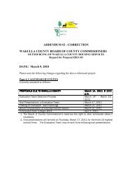
OCHLOCKONEE BAY TRAIL – PHASE IV FDIP PROJECT # 414032-1-58-01FEDERAL PROJECT # S E 8886 (004)SECTION 00410 – BID SCHEDULEBID SCHEDULEProject Title: OCHLOCKONEE BAY TRAIL – PHASE IVProject No.: ITB 2012-10CALENDAR OF EVENTSEVENTDATE & LOCATIONITB Released and AdvertisedThurs., May 17, 2012 8:00 a.m.Technical Questions Due from Prospective Respondents Wed., May 23, 2012MANDATORY PRE-BID MEETING29 ARRAN RD. CRAWFORDVILLE, FLThurs., May 24, 2012 10:00a.m.Responses to Technical Questions Posted Fri., May 25, 2012Prequalification <strong>Documents</strong> Submitted to BOCC Thurs., May 31, 2012Vendor Prequalification List Posted Mon., June 4, 2012Prequalified Vendor Questions to BOCC June 5 – 11, 2012BOCC Answers to Prequalified Vendor Questions Tues., June 12, 2012BIDS DUE TO BOCCFri., June 15, 2012 10:00 a.m.Posting of Intended Award Thurs., June 21, 2012To Board for Final Approval Mon., July 16, 2012Anticipated Start DateUpon Notice to Proceed<strong>Bid</strong> Format/Schedule:Payment for the various item s of the <strong>Bid</strong> Schedul e shall include all compensation for furnishingtools, equipment, supplies, and manufactured articles, labor operations, permit fees, licenses, taxes,insurances, bonds, overhead and profit, and incidentals appurtenances thereto, and including all costsof compliance with the regulations of public agencies having jurisdiction, including theOccupational Safety and Health Administration of the US Department of Labor (OSHA), FDEP,SFWMD, and <strong>Wakulla</strong> <strong>County</strong> Health Department. No separate payment will be made for any itemthat is not specifically set forth in the <strong>Bid</strong> Schedule, and all costs therefore shall be included in theprices named in the Schedule for the various appurtenant items of work.The bidder shall subm it a bid on all item s or the bid shall be considered irregular. The Ownerreserves the right to accept or reject the bid. The Owner, or his representative, further reserves theunqualified right to determ ine whether any particular item or items or materials, equipment, orwhatsoever is an approved equal, and reserves the unqualified right to a final decision regarding theapproval or rejection of the same.SECTION 00410 – BID SCHEDULE PAGE 1 OF 2
OCHLOCKONEE BAY TRAIL – PHASE IV FDIP PROJECT # 414032-1-58-01FEDERAL PROJECT # S E 8886 (004)Note: LF = Linear Foot LS = Lump Sum SF = Square FootLB = Pounds CY = Cubic Yard TN = TonEA = EachSY = Square Yard•••Written Unit Prices shall take precedence over Amount •••ITEM DESCRIPTION QUANTITY UNITROADWAY0101-1 MOBILIZATION 1 LS0102-1 MAINTENANCE OF TRAFFIC 1 LS0104-10-3 SEDIMENT BARRIER, SILT FENCE 25,006 LF0104-11 FLOATING TURBIDITY BARRIER 44 LF0107-1 LITTER REMOVAL 51.96 AC0107-2 MOWING 51.96 AC0110-1-1 CLEARING & GRUBBING 1 / 13.38 LS/AC0120-1 REGULAR EXCAVATION 4,771 CY0120-6 EMBANKMENT 3,032 CY0160-4 TYPE B STABILIZATION 33,381 SY0162-1-11 PREPARED SOIL LAYER, 6” 41,676 SY285-701 OPTIONAL BASE, BASE GROUP 01 23,927 SY0334-1-12 SP ASPHALTIC CONCRETE, TRAFFIC B 1,215.6 TN0400-1-2 CLASS I CONCRETE, ENDWALLS 27.5 CY0430-175-124 PIPE CULVERT, OPT. MAT., ROUND, 24”, S/CD 68 LF0522-2 CONCRETE SIDEWALK, 6” 627 SY0527-1 DETECTABLE WARNING ON EXIST. SURFACE 3 EA0570-1-2 PERFORMANCE TURF, SOD 41,676 SYSIGNING AND MARKING0700-20-11 SINGLE POST SIGN, F&I, LESS THAN 12 23 AS0700-20-40 SINGLE POST SIGN, RELOCATE 4 AS0700-21-40 MULTI POST SIGN, RELOCATE 1 AS0701-11-111AUD & VIB PAVEMENT MARKINGS, STD.,WHITE, SOLID, 6”1.050 NM0705-10-2 OBJECT MARKER, TYPE 2 22 EA0710-90 PAINT FINAL SURFACE 1 LSUNITPRICETOTAL BASE BIDCOSTSECTION 00410 – BID SCHEDULE PAGE 2 OF 2
OCHLOCKONEE BAY TRAIL – PHASE IV FDIP PROJECT # 414032-1-58-01FEDERAL PROJECT # S E 8886 (004)SECTION 00420 – BIDDER’S QUALIFICATION STATEMENTBIDDER’S QUALIFICATION STATEMENTThe undersigned guarantees the truth and accuracy of all statements and answers herein contained.Include additional sheets if necessary. Print in ink or type all answers.Any <strong>Bid</strong>ders proposing to be qualified to perform the Work are advised that they must address eachitem of this sheet, giving full descriptions of the material and equipment that they propose to furnish.Any information omitted will be sufficient reason for refusal to qualify.<strong>Bid</strong>ders shall be prequalified with FDOT in a combination of work classes that equates to at least50% of the normal work: DRAINAGE 5% FLEXIBLE PAVING 21% GRADING 26% HOT PLANT-MIXED BITUMEN COURSES 9% MAINTENANCE OF TRAFFIC CERTIFICATION 6%A copy of the <strong>Bid</strong>der’s Qualifications Letter must be attached to the bid. Failure to do so mayresult in the Board deeming the bid non-compliant, subjecting it to disqualification.STATEMENT OF EXPERIENCE OF BIDDERThe <strong>Bid</strong>der is required to state below what work of similar magnitude is a judge of hisexperience, skill and business standing and of his ability to conduct the work as completely andas rapidly as required under the terms of the contract.Project and LocationReference1.________________________________ ___________________________________________________________ ___________________________2.________________________________ ___________________________________________________________ ___________________________3.________________________________ ___________________________________________________________ ___________________________4.________________________________ ___________________________SECTION 00420 – BIDDERS QUALIFICATION STATEMENT PAGE 1 OF 5
OCHLOCKONEE BAY TRAIL – PHASE IV FDIP PROJECT # 414032-1-58-01FEDERAL PROJECT # S E 8886 (004)________________________________ ___________________________5.________________________________ ___________________________________________________________ ___________________________Dated ___________<strong>Bid</strong>der ___________________________By ___________________________Experience1. How many years has your organization been in business as a contractor?______________________________________________________________________________________________________________________________________________________________________________________________________________________________2. Have you ever failed to complete the work awarded to you within the specified contract timein the last five (5) years? If so, where, when, and why? Attach sheet, if necessary._____________________________________________________________________________________________________________________________________________________________________________________________________________________________________________________________________________________________________________________________________________________________________________3. Give names, addresses, and telephone numbers of three (3) individuals or corporations (notincluding <strong>Wakulla</strong> <strong>County</strong> personnel) for which you have performed work and that can becontacted as a reference. Attach sheet, if necessary.____________________________________________________________________________________________________________________________________________________________________________________________________________________________________________________________________________________________________4. Complete the table below as fully as possible, describing projects which have been workedon or completed during the past five (5) years.SECTION 00420 – BIDDERS QUALIFICATION STATEMENT PAGE 2 OF 5
OCHLOCKONEE BAY TRAIL – PHASE IV FDIP PROJECT # 414032-1-58-01FEDERAL PROJECT # S E 8886 (004)Location andType of WorkOWNERName/CityConsultingEngineerYearCompletedContractPriceGeneral5. Describe your present workload. Do you have project underway which might interfere withthe start of this Work and completion on schedule?__________________________________________________________________________________________________________________________________________________________________________________________________________________________________________________________________________________________________________________________________________________________________________________6. List all past litigations, arbitrations, mediations, informal settlement discussions or disputesinvolving your company or projects for the past five (5) years and final outcome. Fullydescribe the circumstances (use additional sheets if necessary).__________________________________________________________________________________________________________________________________________________________________________________________________________________________________________________________________________________________________________________________________________________________________________________SECTION 00420 – BIDDERS QUALIFICATION STATEMENT PAGE 3 OF 5
OCHLOCKONEE BAY TRAIL – PHASE IV FDIP PROJECT # 414032-1-58-01FEDERAL PROJECT # S E 8886 (004)7. Are you presently involved in any litigations, mediation, licensing, proceedings orarbitration? If so, describe fully the circumstances and dollar amounts associated therewith.Attach sheet, if necessary.____________________________________________________________________________________________________________________________________________________________________________________________________________________________________________________________________________________________________________________________________________________________________________________________________________________________________________________________8. Use the following space to give a summary of the Financial Statement of your organization.(List assets and liabilities for the past five (5) years, and use additional sheet if necessary):_________________________________________________________________________________________________________________________________________________________________________________________________________________________________________________________________________________________________________________________________________________________________________________9. Has your corporation(s) been declared insolvent and/or had a bond called or pulled on aproject?__________________________________________________________________________________________________________________________________________________________________________________________________________________________________________________________________________________________________________________________________________________________________________________10. What bonding companies do you use and what is your current bonding rating?__________________________________________________________________________________________________________________________________________________________________________________________________________________________________________________________________________________________________________________________________________________________________________________11. State the true and exact, correct, and complete name under which you do business.BIDDERIS:_______________________________________________________________________SECTION 00420 – BIDDERS QUALIFICATION STATEMENT PAGE 4 OF 5
OCHLOCKONEE BAY TRAIL – PHASE IV FDIP PROJECT # 414032-1-58-01FEDERAL PROJECT # S E 8886 (004)______________________________________________________________________________(Signature)______________________________________________________________________________(Name)______________________________________________________________________________(Title)______________________________________________________________________________(Company)_______________________________________________________________________________(Date)SECTION 00420 – BIDDERS QUALIFICATION STATEMENT PAGE 5 OF 5
OCHLOCKONEE BAY TRAIL – PHASE IV FDIP PROJECT # 414032-1-58-01FEDERAL PROJECT # S E 8886 (004)SECTION 00500 – CONSTRUCTION AGREEMENTCONSTRUCTION AGREEMENTWAKULLA COUNTY, a political subdivision of the State of Florida, by and through itsBoard of <strong>County</strong> Commissioners, situated at 3093 Crawfordville Highway, Crawfordville, Florida32327 (the "<strong>County</strong>"), hereby contracts with _____________________________ (the "Contractor")of ______________________________________________________________________ (address)a __________________________contractor licensed to perform all work in the State of Florida inconnection with the <strong>County</strong>'s Project No. ITB-2012-10 (the "Project"), as said work is set forthin the Plans prepared by THE LPA GROUP INCORPORATED , the Engineer (the"Design Professional"), other Contract <strong>Documents</strong> hereafter specified (the "Work") and theSpecifications assembled by THE LPA GROUP INCORPORATED.The <strong>County</strong> and the Contractor, for the consideration herein set forth, agree as follows:Section 1.Contract <strong>Documents</strong>.A. The Contract <strong>Documents</strong> consist of this Agreement, the Exhibits described in Section6 hereof, the Legal Advertisement, the Instructions to <strong>Bid</strong>ders, the Proposal and any duly executedand issued addenda, Change Orders, Work Directive Changes, Field Orders, Work Authorizationsand amendments relating thereto. All of the foregoing Contract <strong>Documents</strong> are incorporated byreference and made a part of this Agreement (all of said documents including the Agreementsometimes being referred to herein as the "Contract <strong>Documents</strong>" and sometimes as the"Agreement"). A copy of the Contract <strong>Documents</strong> shall be maintained by Contractor at the Projectsite at all times during the performance of the Work.B. The <strong>County</strong> shall furnish to the Contractor up to five (5) sets of the Contract<strong>Documents</strong> as are reasonably necessary for execution of the Work. Additional copies of theContract <strong>Documents</strong> shall be furnished, upon request, at the cost of reproduction.Section 2.Scope of Work.The Contractor agrees to furnish and pay for all management, supervision, financing, labor,materials, tools, fuel, supplies, utilities, equipment and services of every kind and type necessary todiligently, timely, and fully perform and complete in a good and workmanlike manner the workrequired by this Agreement.Section 3.Contract Amount.In consideration of the faithful performance by the Contractor of the covenants in thisAgreement to the full satisfaction and acceptance of the <strong>County</strong>, the <strong>County</strong> agrees to pay, or causeto be paid, to Contractor the following amount (herein "Contract Amount"), in accordance with theterms of this Agreement: $_______________________or in WORDS_____________________________________________________________________________ .SECTION 00500 – CONSTRUCTION AGREEMENT PAGE 1 OF 5
OCHLOCKONEE BAY TRAIL – PHASE IV FDIP PROJECT # 414032-1-58-01FEDERAL PROJECT # S E 8886 (004)Section 4.Bonds.A. The Contractor shall provide Performance and Payment Bonds, in the form prescribedin Section 00610 and Section 00620 of the Contract <strong>Documents</strong>, in the amount of 100% of theContract Amount, the costs of which are to be paid by Contractor. The Performance and PaymentBonds shall be underwritten by a surety authorized to do business in the State of Florida andotherwise acceptable to the <strong>County</strong>; provided, however, the surety shall be rated as "A-" or better asto general policy holders rating and Class V or higher rating as to financial size category and theamount required shall not exceed 5% of the reported policy holders surplus, all as reported in themost current Best Key Rating Guide, published by A.M. Best Company, Inc. of 75 Fulton Street,New York, New York 10038.B. If the surety for any bond furnished by Contractor is declared bankrupt, becomesinsolvent, its right to do business is terminated in the State of Florida, or it ceases to meet therequirements imposed by the Contract <strong>Documents</strong>, the Contractor shall, within five (5) calendar daysthereafter, substitute another bond and surety, both of which shall be subject to the <strong>County</strong>'sapproval.Section 5.Contract Time and Liquidated DamagesA. Time is of the essence in the performance of the Work under this Agreement. The"Commencement Date" shall be established in the Notice to Proceed to be issued by the <strong>County</strong>.The Contractor shall commence the Work within five (5) calendar days from the CommencementDate. No Work shall be performed at the Project site prior to the Commencement Date. Any Workperformed by the Contractor prior to the Commencement Date shall be at the sole risk of theContractor. The Work shall be substantially completed within 212 calendar days from theCommencement Date. The date of substantial completion of the Work (or designated portionsthereof) is the date certified by the Design Professional when construction is sufficiently complete,in accordance with the Contract <strong>Documents</strong>, so the <strong>County</strong> can occupy or utilize the Work (ordesignated portions thereof) for the use for which it is intended. The Work shall be fully completedand ready for final acceptance by the <strong>County</strong> within 242 calendar days from the CommencementDate (herein "Contract Time").B. The <strong>County</strong> and the Contractor recognize that, since time is of the essence for thisAgreement, the <strong>County</strong> will suffer financial loss if the Work is not substantially completed withinthe time specified above, as said time may be adjusted as provided for herein. Should the Contractorfail to substantially complete the Work within the time period noted above, the <strong>County</strong> shall beentitled to assess, as liquidated damages, but not as a penalty, $500.00 for each calendar daythereafter until substantial completion is achieved. The Project shall be deemed to be substantiallycompleted on the date the Design Professional issues a Substantial Completion Certificate pursuantto the terms hereof. The Contractor hereby expressly waives and relinquishes any right which it mayhave to seek to characterize the above noted liquidated damages as a penalty, which the parties agreerepresents a fair and reasonable estimate of the <strong>County</strong>'s actual damages at the time of contracting ifthe Contractor fails to substantially complete the Work in a timely manner.SECTION 00500 – CONSTRUCTION AGREEMENT PAGE 2 OF 5
OCHLOCKONEE BAY TRAIL – PHASE IV FDIP PROJECT # 414032-1-58-01FEDERAL PROJECT # S E 8886 (004)C. When any period of time is referenced by days herein, it shall be computed to excludethe first day and include the last day of such period. If the last day of any such period falls on aSaturday or Sunday or on a day made a legal holiday by the law of the applicable jurisdiction, suchday shall be omitted from the computation, and the last day shall become the next succeeding daywhich is not a Saturday, Sunday or legal holiday.Section 6.Exhibits Incorporated.The following documents are expressly agreed to be incorporated by reference and made apart of this Agreement:A. 00010 Statement of WorkB. 00050 Special Prequalification RequirementsC. 00100 Instructions to <strong>Bid</strong>dersD. 00400 <strong>Bid</strong> ProposalE. 00410 <strong>Bid</strong> ScheduleF. 00420 <strong>Bid</strong>der’s Qualification StatementG. 00500 Construction AgreementH. 00610 Performance BondI. 00620 Public Payment BondJ. 00700 General ConditionsK. 00710 Insurance RequirementsL. 00850 Release and AffidavitM. 00860 Conflict of Interest Disclosure StatementN. 00870 Drug Free Workplace CertificationsO. 00880 Ethics ClauseP. 00890 Non-Collusion AffidavitQ. 00900 Change Order FormR. FDOT Special ProvisionsS. FDOT Supplemental SpecificationsT. FDOT Local Agency Program/Federal-Aid Contract RequirementsU. PermitsSection 7.Notices.A. All notices required or made pursuant to this Agreement by the Contractor to the<strong>County</strong> shall be in writing and delivered by hand or by United States Postal Service Department,first class mail, postage pre-paid, return receipt requested, addressed to the following:<strong>Wakulla</strong> <strong>County</strong> Administrator3093 Crawfordville HighwayCrawfordville, Florida 32327SECTION 00500 – CONSTRUCTION AGREEMENT PAGE 3 OF 5
OCHLOCKONEE BAY TRAIL – PHASE IV FDIP PROJECT # 414032-1-58-01FEDERAL PROJECT # S E 8886 (004)With a copy to:Sheree KeelerGrants Coordinator, <strong>Wakulla</strong> <strong>County</strong>Post Office Box 309Crawfordville, Florida 32326B. All notices required or made pursuant to this Agreement by the <strong>County</strong> to Contractorshall be made in writing and shall be delivered by hand or by United States Postal ServiceDepartment, first class mail, postage pre-paid, return receipt requested, or by Federal Express,addressed to the following:Corporate Name of Contractor:Address (including city, state and zip):Name of person with their title to whoseattention the notice should be sent:Telephone and Fax numbers:________________________________________________________________________________________________________________________________________________________________________________(T)_____________________(F)___________________C. Either party may change its above noted address by giving written notice to the otherparty in accordance with the requirements of this Section.Section 8.Modification.No modification or change to the Agreement shall be valid or binding upon the parties unlessin writing and executed by the party or parties intended to be bound by it.Section 9.Successors and Assigns.Subject to other provisions hereof, the Agreement shall be binding upon and shall inure to thebenefit of the successors and assigns of the parties to the Agreement.Section 10.Governing Law.The Agreement shall be interpreted under and its performance governed by the laws of theState of Florida.Section 11.No Waiver.The failure of the <strong>County</strong> to enforce at any time or for any period of time any one or more ofthe provisions of the Agreement shall not be construed to be and shall not be a waiver of any suchprovision or provisions or of its right thereafter to enforce each and every such provision.Section 12.Entire Agreement.SECTION 00500 – CONSTRUCTION AGREEMENT PAGE 4 OF 5
OCHLOCKONEE BAY TRAIL – PHASE IV FDIP PROJECT # 414032-1-58-01FEDERAL PROJECT # S E 8886 (004)Each of the parties hereto agrees and represents that the Agreement comprises the full andentire agreement between the parties affecting the Work contemplated, and no other agreement orunderstanding of any nature concerning the same has been entered into or will be recognized, and thatall negotiations, acts, work performed, or payments made prior to the execution hereof shall bedeemed merged in, integrated and superseded by the Agreement.Section 13.Severability.Should any provision of the Agreement be determined by a court to be unenforceable, such adetermination shall not affect the validity or enforceability of any other section or part thereof.IN WITNESS WHEREOF, the parties have executed this Agreement on the date(s) indicatedbelow.CONTRACTOR: _____________________________________(Company Name)ATTEST:By:________________________________ (Signature) _________________________ (Printed)Its: ________________________________ (Title)Date: ______________________________Witness:Its:_________________________President/Corporate Secretary/Witness[Corporate Seal]Date:______________________________________________________2nd Witness (if not incorporated)OWNER:(SEAL)Board of <strong>County</strong> Commissioners of <strong>Wakulla</strong> <strong>County</strong>, FloridaBy:______________________________ChairmanClerk: _________________________Date:_________________________________________________________Approved as to Form and Content:<strong>County</strong> AttorneySECTION 00500 – CONSTRUCTION AGREEMENT PAGE 5 OF 5
OCHLOCKONEE BAY TRAIL – PHASE IV FDIP PROJECT # 414032-1-58-01FEDERAL PROJECT # S E 8886 (004)SECTION 00610 – PERFORMANCE BONDBOND NO.________________PERFORMANCE BONDKNOW ALL MEN BY THESE PRESENTS: That __________________________________________________________________________, as Principal, whose principal business address is______________________________________________________________________________and phone number and fax numbers are ___________________________________________,and ____________________________________________________, as Surety, whose principaladdress is__________________________________________________________________________________________________________________________________________________and phone number is: _______________________________________________________ areheld and firmly bound to <strong>Wakulla</strong> <strong>County</strong>, Florida (the "COUNTY"), as Obligee in the sumof:____________________________________________________________________________________________________________________________________________________($_______________________) for the payment whereof we bond ourselves, our heirs,executors, personal representatives, successors and assigns, jointly and severally.WHEREAS, Principal has entered into a contract dated as of the _______ day of________________, 20____, with Obligee for ______________________________________________________________________________________________________________________________________________________________________________________________________________________________________________________WAKULLA COUNTY Project No.:ITB-2011-21 in accordance with drawings and specifications, which contract is incorporated byreference and made a part hereof, and is referred to as the Contract.THE CONDITION OF THIS BOND is that if Principal:1. Performs the Contract at the times and in the manner prescribed in the Contract; and2. Pays Obligee any and all losses, damages, costs and attorneys' fees, includingappellate proceedings, that Obligee sustains because of any default by Principal under the Contract,including, but not limited to, all delay damages, whether liquidated or actual, incurred by Obligee;and3. Performs the guarantee of all work and materials furnished under the Contract for thetime specified in the Contract, then this bond is void; otherwise it remains in full force.Any changes in or under the Contract and compliance or noncompliance with any formalitiesconnected with the Contract or the changes do not affect Surety's obligation under this Bond.The Surety, for value received, hereby stipulates and agrees that no changes, extensions oftime, alterations or additions to the terms of the Contract or other work to be performed hereunder,SECTION 00610 – PERFORMANCE BOND PAGE 1 OF 4
OCHLOCKONEE BAY TRAIL – PHASE IV FDIP PROJECT # 414032-1-58-01FEDERAL PROJECT # S E 8886 (004)or the specifications referred to therein shall in anywise affect its obligations under this bond, and itdoes hereby waive notice of any such changes, extensions of time, alterations or additions to theterms of the Contract or to work or to the specifications.This bond is intended to comply with provisions of Section 255.05, Florida Statutes, and allterms and conditions of said statute are incorporated herein by reference thereto, specificallyincluding but not limited to the notice and time limitation provisions of said section. In the event ofany conflict, ambiguity or discrepancy between Section 255.05, Florida Statutes, and this Bond,Florida Statutes shall control. No right of action shall accrue on this Bond to or, for the use of anyperson or entity other than the COUNTY and those persons or corporations provided for by saidstatute, their heirs, executors, administrators, successors or assigns.It is further agreed and understood that if the COUNTY is required to initiate legalproceedings to recover on this Bond, the COUNTY may also recover its costs relating there to,including a reasonable amount for its attorney’s fees and legal assistant’s fees before trial, at trial, onappeal and in bankruptcy.IN WITNESS WHEREOF, the above parties have executed this instrument this _____ day of___________________,20____, the name of each party being affixed and these presents duly signedby its undersigned representative, pursuant to authority of its governing body.Signed, sealed and deliveredin the presence of:PRINCIPAL:____________________________________________(Company Name of Contractor)By:_________________________________________(Officers Signature)____________________________________________(Officers Name Printed)Witnesses as to PrincipalName:_______________________________(Signature)Its:_______________________________ (Title)STATE OF ______________________________COUNTY OF ____________________________SECTION 00610 – PERFORMANCE BOND PAGE 2 OF 4
OCHLOCKONEE BAY TRAIL – PHASE IV FDIP PROJECT # 414032-1-58-01FEDERAL PROJECT # S E 8886 (004)The foregoing instrument was acknowledged before me this ________day of _______________,20 ______, by _________________________________________________(officer’s name), as__________________________ (title) of _____________________________________________(company name), a(n)____________ (state) corporation, on behalf of the corporation. He/she ispersonally known to me OR has produced _______________________ as identification and did(did not) take an oath.My Commission Expires: _____________________________Signature of Notary :__________________________________(Legibly Printed) __________________________________(AFFIX OFFICIAL SEAL) Notary Public, State of__________Commission No. ____________________ATTEST: SURETY:____________________________________________________________(Printed Company Name)__________________________________________________________________________________________________________________________(Business Address)________________________________(Surety Authorized Signature)________________________(Printed Name)Witness as to Surety ______________________________(Signature)___________________________(Printed Name)OR_______________________________As Attorney in Fact (Signature)______________________________(Printed Name)(Attach Power of Attorney)Witnessed by: _____________________________ ______________________(Signature)(Printed Name)______________________________________(Business Address)STATE OF _____________________________________(Telephone Number)SECTION 00610 – PERFORMANCE BOND PAGE 3 OF 4
OCHLOCKONEE BAY TRAIL – PHASE IV FDIP PROJECT # 414032-1-58-01FEDERAL PROJECT # S E 8886 (004)COUNTY OF ___________The foregoing instrument was acknowledged before me this ______day of _____________, 20____,by____________________________ (officer’s name), as___________________________(title) of ___________________________________ Surety, on behalf of Surety. He/She ispersonally known to me OR has produced __________________________________ asidentification and who did (did not) take an oath.My Commission Expires: _____________________________Signature of Notary :__________________________________(Legibly Printed) __________________________________(AFFIX OFFICIAL SEAL) Notary Public, State of__________Commission No. ____________________SECTION 00610 – PERFORMANCE BOND PAGE 4 OF 4
OCHLOCKONEE BAY TRAIL – PHASE IV FDIP PROJECT # 414032-1-58-01FEDERAL PROJECT # S E 8886 (004)SECTION 00620 – PUBLIC PAYMENT BONDBOND No. _______________________PUBLIC PAYMENT BONDKNOW ALL MEN BY THESE PRESENTS: That__________________________________________________________________________, as Principal, whose principal business address is:______________________________________________________________________________and phone number and fax numbers are: _____________________________________________and ____________________________________________________________, as Surety, whoseprincipal address is:____________________________________________________________________________________________________________________________________________________________and phone number and fax numbers are: ______________________________________ are heldand firmly bound to WAKULLA COUNTY, FLORIDA (the "COUNTY") as Obligee in the sumof____________________________________________________________________________________________________________________________________ ($___________________)for the payment whereof we bind ourselves, our heirs, executors, personal representatives,successors and assigns, jointly and severally.WHEREAS, Principal has entered into a contract dated as of the ____ day of _________,20___, with Obligee for __________________________________________________________in accordance with drawings and specifications, which contract is incorporated by reference andmade a part hereof, and this referred to as the Contract.THE CONDITION OF THIS BOND is that if Principal promptly makes payment to allclaimants as defined in Section 255.05(1), Florida Statutes, supplying Principal with labor, materialsor supplies, used directly or indirectly by Principal in the prosecution of the work provided for in theContract, then is bond is void; otherwise it remains in full force.Any changes in or under the Contract and compliance or noncompliance with any formalitiesconnected with the Contract or the changes do not affect Surety's obligation under this Bond.The provisions of this bond are subject to the time limitations of Section 255.05(2). In no event willthe Surety be liable in the aggregate to claimants for more than the penal sum of this Payment Bond,regardless of the number of suits that may be filed by claimants.IN WITNESS WHEREOF, the above parties have executed this instrument this _____ day of_____________, 20___, the name of each party being affixed and these presents duly signed by itsunder-signed representative, pursuant to authority of its governing body.Signed, sealed and delivered in the presence of:SECTION 00620 – PUBLIC PAYMENT BOND PAGE 1 OF 3
OCHLOCKONEE BAY TRAIL – PHASE IV FDIP PROJECT # 414032-1-58-01FEDERAL PROJECT # S E 8886 (004)PRINCIPAL: ___________________________________________________________(Company Name of Contractor)By:_______________________________________ (Officer’s Signature)_______________________________________ (Officer’s Name Printed)Witnesses as to Principal Name:_____________________________ (Signature)Its:_____________________________ (Title)STATE OF ________________COUNTY OF _______________The foregoing instrument was acknowledged before me this ___day of ______________,20_____, by_______________________________________________ (officer’s name) , as_________________________________ (title) of __________________________________, a____________corporation, on behalf of the corporation. He/she is personally known to me ORhas produced__________________ as identification and did (did not) take an oath.My Commission Expires: ______________________________Signature of Notary: _____________________________________(Legibly Printed) _____________________________________(AFFIX OFFICIAL SEAL) Notary Public, State of __________Commission No.:____________ATTEST: SURETY:________________________________________________________(Printed Company Name)________________________________________________________________________________________________________________(Business Address)_________________________________________(Surety Authorized Signature)______________________________(Printed Name)Witness as to Surety: ______________________________ (Signature)______________________________(Printed Name)ORSECTION 00620 – PUBLIC PAYMENT BOND PAGE 2 OF 3
OCHLOCKONEE BAY TRAIL – PHASE IV FDIP PROJECT # 414032-1-58-01FEDERAL PROJECT # S E 8886 (004)__________________________________As Attorney in Fact (Signature)______________________________(Printed Name)(Attach Power of Attorney)Witnessed by: __________________________(Signature)____________________________________________________________(Business Address)______________________________(Printed Name)_______________________________(Telephone Number)STATE OF ____________COUNTY OF ___________The foregoing instrument was acknowledged before me this ____day of _____________, 20__, by________________________________ (officer’s name), as_______________________(title) of__________________________________ Surety, on behalf of Surety. He/She ispersonally known to me OR has produced __________________________________ asidentification and who did (did not) take an oath.My Commission Expires: ____________Signature of Notary: ____________________________(Legibly Printed) ____________________________(AFFIX OFFICIAL SEAL) Notary Public, State of __________Commission No:__________________________SECTION 00620 – PUBLIC PAYMENT BOND PAGE 3 OF 3
OCHLOCKONEE BAY TRAIL – PHASE IV FDIP PROJECT # 414032-1-58-01FEDERAL PROJECT # S E 8886 (004)SECTION 00700 – GENERAL CONDITIONSGENERAL TERMS AND CONDITIONS1. INTENT OF CONTRACT DOCUMENTS.1.1. It is the intent of the Contract <strong>Documents</strong> to describe a functionally complete project(or portion thereof) to be constructed in accordance with the Contract <strong>Documents</strong>. Any work,materials or equipment that may reasonably be inferred from the Contract <strong>Documents</strong> as beingrequired to produce the intended result shall be supplied whether or not specifically called for.When words which have a well known technical or trade meaning are used to describe work,materials or equipment, such words shall be interpreted in accordance with that meaning. Referenceto standard specifications, manuals or codes of any technical society, organization or association orto the laws or regulations of any governmental authority having jurisdiction over the Project,whether such reference be specific or by implication, shall mean the latest standard specification,manual, code, law or regulation in effect at the time the Work is performed, except as may beotherwise specifically stated herein.1.2. If before or during the performance of the Work, Contractor discovers a conflict,error or discrepancy in the Contract <strong>Documents</strong>, Contractor immediately shall report same to DesignProfessional in writing and before proceeding with the Work affected thereby shall obtain a writteninterpretation or clarification from the Design Professional. Contractor shall take fieldmeasurements and verify field conditions and shall carefully compare such field measurements andconditions and other information known to Contractor with the Contract <strong>Documents</strong> beforecommencing any portion of the Work.1.3. Drawings are intended to show general arrangements, design and extent of Work andare not intended to serve as shop drawings. Specifications are separated into divisions forconvenience of reference only and shall not be interpreted as establishing divisions for the Work,trades, subcontracts, or extent of any part of the Work. In the event of a discrepancy between oramong the drawings, specifications or other Contract Document provisions, Contractor shall berequired to comply with the provision which is the more restrictive or stringent requirement upon theContractor, as determined by the Design Professional. Unless otherwise specifically mentioned, allanchors, bolts, screws, fittings, fillers, hardware, accessories, trim and other parts required inconnection with any portion of the Work to make a complete, serviceable, finished and first qualityinstallation shall be furnished and installed as part of the Work, whether or not called for by theContract <strong>Documents</strong>.2. INVESTIGATION AND UTILITIES.2.1. Contractor shall have the sole responsibility of satisfying itself concerning the natureand location of the Work and the general and local conditions, and particularly, but withoutlimitation, with respect to the following: those affecting transportation, access, disposal, handlingand storage of materials; availability and quality of labor; water and electric power; availability andcondition of roads; work area; living facilities; climatic conditions and seasons; physical conditionsSECTION 00700 – GENERALCONDITIONS PAGE 1 OF 21
OCHLOCKONEE BAY TRAIL – PHASE IV FDIP PROJECT # 414032-1-58-01FEDERAL PROJECT # S E 8886 (004)at the work-site and the project area as a whole; topography and ground surface conditions; natureand quantity of the surface materials to be encountered; subsurface conditions; equipment andfacilities needed preliminary to and during performance of the Work; and all other costs associatedwith such performance. The failure of Contractor to acquaint itself with any applicable conditionsshall not relieve Contractor from any of its responsibilities to perform under the Contract<strong>Documents</strong>, nor shall it be considered the basis for any claim for additional time or compensation.2.2. Contractor shall locate all existing roadways, railways, drainage facilities and utilityservices above, upon, or under the Project site, said roadways, railways, drainage facilities andutilities being referred to in this Sub-Section 2.2 as the "Utilities". Contractor shall contact theowners of all Utilities to determine the necessity for relocating or temporarily interrupting anyUtilities during the construction of the Project. Contractor shall schedule and coordinate its Workaround any such relocation or temporary service interruption. Contractor shall be responsible forproperly shoring, supporting and protecting all Utilities at all times during the course of the Work.Relocation or shutdown of COUNTY facilities must be requested by the Contractor in writing aminimum of ten (10) calendar days prior to the proposed Work. The COUNTY shall have the finaldecision with respect to whether the relocation or shutdown is required and when the relocation orshutdown of facilities may take place. The Work may need to be performed at night or on weekendsto minimize the interruption of service or to meet the operational needs of the COUNTY's facilities.3. SCHEDULE.3.1. The Contractor, within ten (10) calendar days after receipt of a Notice of Award, shallprepare and submit to the COUNTY and Design Professional, for their review and approval, aprogress schedule for the Project (herein "Progress Schedule"). The Progress Schedule shall relateto all Work required by the Contract <strong>Documents</strong> and shall provide for expeditious and practicableexecution of the Work within the Contract Time. The Progress Schedule shall indicate the dates forstarting and completing the various stages of the Work.3.2. The Progress Schedule shall be updated monthly by the Contractor. All monthlyupdates to the Progress Schedule shall be subject to the COUNTY's and Design Professional'sreview and approval. Contractor shall submit the updates to the Progress Schedule with its monthlyApplications for Payment noted below. The COUNTY's and Design Professional's review andapproval of the submitted Progress Schedule updates shall be a condition precedent to theCOUNTY's obligation to pay Contractor.4. PROGRESS PAYMENTS.4.1. Prior to submitting its first monthly Application for Payment, Contractor shall submitto the COUNTY and the Design Professional, for their review and approval, a schedule of valuesbased upon the Contract Price, listing the major elements of the Work and the dollar value for eachelement. After its approval by the COUNTY and Design Professional, this schedule of values shallbe used as the basis for the Contractor's monthly Applications for Payment. This schedule shall beupdated and submitted each month to the Design Professional along with a completed and notarizedcopy of the Application for Payment form. A sample Application for Payment form is included withthese General Terms and Conditions.SECTION 00700 – GENERALCONDITIONS PAGE 2 OF 21
OCHLOCKONEE BAY TRAIL – PHASE IV FDIP PROJECT # 414032-1-58-01FEDERAL PROJECT # S E 8886 (004)4.2. Prior to submitting its first monthly Application for Payment, Contractor shall submitto the COUNTY and the Design Professional a complete list of all its proposed subcontractors andmaterialmen, showing the work and materials involved and the dollar amount of each proposedsubcontract and purchase order. The first Application for Payment shall be submitted no earlier thanthirty (30) days after the Commencement Date.4.3. If payment is requested on the basis of materials and equipment not incorporated intothe Project, but delivered and suitably stored at the site or at another location agreed to by theCOUNTY in writing, the Application for Payment shall also be accompanied by a bill of sale,invoice or other documentation warranting that the COUNTY has received the materials andequipment free and clear of all liens, charges, security interests and encumbrances, together withevidence that the materials and equipment are covered by appropriate property insurance and otherarrangements to protect the COUNTY's interest therein, all of which shall be subject to theCOUNTY's satisfaction.4.4. Contractor shall submit six (6) copies of its monthly Application for Payment to theDesign Professional on or before the 25th day of each month for work performed during the previousmonth. Invoices received after the 25th day of each month shall be considered for payment as part ofthe next month's application. Within ten (10) calendar days after receipt of each Application forPayment, the Design Professional shall either:4.4.1 Indicate his approval of the requested payment;4.4.2 Indicate his approval of only a portion of the requested payment, stating in writinghis reasons therefore; or4.4.3 Return the Application for Payment to the Contractor indicating, in writing, thereason for refusing to approve payment.In the event of a total denial and return of the Application for Payment by the DesignProfessional, the Contractor may make the necessary corrections and resubmit the Application forPayment. The COUNTY shall, within thirty (30) calendar days after COUNTY approval of anApplication for Payment, pay the Contractor the amounts so approved. Provided, however, in noevent shall the COUNTY be obligated to pay any amount greater than that portion of the Applicationfor Payment approved by the Design Professional.4.5. The COUNTY shall initially retain ten percent (10%) of the gross amount of eachmonthly payment request or ten percent (10%) of the portion thereof approved by the DesignProfessional for payment, whichever is less. After 50% of the services are completed, the COUNTYwill reduce the retainage to five percent (5%) of each subsequent progress payment. Such sums shallbe accumulated and released to Contractor with final payment.For purposes of determining 50% completion, stored material and general job costs such asmobilization, bonds, insurance, field office costs and like costs shall be excluded. Additionally, forpurposes of this determination, each major discipline (electrical and instrumentation, structural, andSECTION 00700 – GENERALCONDITIONS PAGE 3 OF 21
OCHLOCKONEE BAY TRAIL – PHASE IV FDIP PROJECT # 414032-1-58-01FEDERAL PROJECT # S E 8886 (004)mechanical) must independently achieve 50% completion in order for the project services to bedeemed 50% complete4.6. Monthly payments to Contractor shall in no way imply approval or acceptance ofContractor's work.4.7. Each Application for Payment shall be accompanied by a Release and Affidavit, inthe form attached as Section 00850, showing that all materials, labor, equipment and other billsassociated with that portion of the Work for which payment is being requested have been paid infull. The COUNTY shall not be required to make payment until and unless these affidavits arefurnished by the Contractor.4.8. Contractor agrees and understands that funding limitations exist and that theexpenditure of funds must be spread over the duration of the Project at regular intervals based on theContract Amount and Progress Schedule. Accordingly, prior to submitting its first monthlyApplication for Payment, Contractor shall prepare and submit for the COUNTY's and DesignProfessional's review and approval, a detailed Project Funding Schedule, which shall be updated asnecessary and approved by the COUNTY to reflect approved adjustments to the Contract Amountand Contract Time. No voluntary acceleration or early completion of the Work shall modify thetime of payments to Contractor as set forth in the approved Project Funding Schedule.5. PAYMENTS WITHHELD.5.1. The Design Professional or the COUNTY may decline to approve any Application forPayment, or portions thereof, because of subsequently discovered evidence or subsequentinspections. The Design Professional or the COUNTY may nullify the whole or any part of anyapproval for payment previously issued and the COUNTY may withhold any payments otherwisedue Contractor under this Agreement or any other agreement between the COUNTY and Contractor,to such extent as may be necessary in the COUNTY's opinion to protect it from loss because of:5.1.1 Defective Work not remedied;5.1.2 Third party claims filed or reasonable evidence indicating probable filing of suchclaims;5.1.3 Failure of Contractor to make payment properly to subcontractors or for labor,materials or equipment;5.1.4 Reasonable doubt that the Work can be completed for the unpaid balance of theContract Amount;5.1.5 Reasonable indication that the Work will not be completed within the Contract Time;5.1.6 Unsatisfactory prosecution of the Work by the Contractor;SECTION 00700 – GENERALCONDITIONS PAGE 4 OF 21
OCHLOCKONEE BAY TRAIL – PHASE IV FDIP PROJECT # 414032-1-58-01FEDERAL PROJECT # S E 8886 (004)5.1.7 Failure to provide accurate and current "As-Builts"; or5.1.8 Any other material breach of the Contract <strong>Documents</strong>.5.2. If these conditions in Subsection 5.1 are not remedied or removed, the COUNTYmay, after three (3) days written notice, rectify the same at Contractor's expense. The COUNTYalso may offset against any sums due Contractor the amount of any liquidated or unliquidatedobligations of Contractor to the COUNTY, whether relating to or arising out of this Agreement orany other agreement between Contractor and the COUNTY.6. FINAL PAYMENT.6.1. The COUNTY shall make final payment to Contractor within thirty (30) calendardays after the Work is finally inspected and accepted by both the COUNTY and the DesignProfessional in accordance with Section 20.1 herein, provided that Contractor first, and as an explicitcondition precedent to the accrual of Contractor's right to final payment, shall have furnished theCOUNTY with a properly executed and notarized copy of the Release and Affidavit attached asSection 00850, as well as, a duly executed copy of the Surety's consent to final payment and suchother documentation that may be required by the Contract <strong>Documents</strong> and the COUNTY.6.2. Contractor's acceptance of final payment shall constitute a full waiver of any and allclaims by Contractor against the COUNTY arising out of this Agreement or otherwise relating to theProject, except those previously made in writing and identified by Contractor as unsettled at the timeof the final Application for Payment. Neither the acceptance of the Work nor payment by theCOUNTY shall be deemed to be a waiver of the COUNTY's right to enforce any obligations ofContractor hereunder or to the recovery of damages for defective Work not discovered by the DesignProfessional or the COUNTY at the time of final inspection.7. SUBMITTALS AND SUBSTITUTIONS.7.1. Contractor shall carefully examine the Contract <strong>Documents</strong> for all requirements forapproval of materials to be submitted such as a schedule of values, safety manual, shop drawings,data, test results, schedules and samples. Contractor shall submit all such materials at its ownexpense and in such form as required by the Contract <strong>Documents</strong> in sufficient time to prevent anydelay in the delivery of such materials and the installation thereof.7.2. Whenever materials or equipment are specified or described in the Contract<strong>Documents</strong> by using the name of a proprietary item or the name of a particular supplier, the namingof the item is intended to establish the type, function and quality required. Unless the name isfollowed by words indicating that no substitution is permitted, materials or equipment of othersuppliers may be accepted by the COUNTY if sufficient information is submitted by Contractor toallow the COUNTY to determine that the material or equipment proposed is equivalent or betterthan to that named. Requests for review of substitute items of material and equipment will not beaccepted by the COUNTY from anyone other than Contractor and all such requests must beSECTION 00700 – GENERALCONDITIONS PAGE 5 OF 21
OCHLOCKONEE BAY TRAIL – PHASE IV FDIP PROJECT # 414032-1-58-01FEDERAL PROJECT # S E 8886 (004)submitted by Contractor to Design Professional within thirty (30) calendar days after Notice ofAward is received by Contractor.7.3. If Contractor wishes to furnish or use a substitute item of material or equipment,Contractor shall make application to the Design Professional for acceptance thereof, certifying thatthe proposed substitute shall perform adequately the functions and achieve the results called for bythe general design, be similar and of equal substance to that specified and be suited to the same useas that specified. The application shall state that the evaluation and acceptance of the proposedsubstitute will not prejudice Contractor's achievement of substantial completion on time, whether ornot acceptance of the substitute for use in the Work will require a change in any of the Contract<strong>Documents</strong> (or in the provisions of any other direct contract with the COUNTY for the Project) toadapt the design to the proposed substitute and whether or not incorporation or use of the substitutein connection with the Work is subject to payment of any license fee or royalty. All variations of theproposed substitute from that specified will be identified in the application and availablemaintenance, repair and replacement service shall be indicated. The application also shall contain anitemized estimate of all costs that will result, directly or indirectly, from acceptance of suchsubstitute, including costs for redesign and claims of other contractors affected by the resultingchange, all of which shall be considered by the Design Professional in evaluating the proposedsubstitute. The Design Professional may require Contractor to furnish at Contractor's expenseadditional data about the proposed substitute.7.4. If a specific means, method, technique, sequence or procedure of construction isindicated in or required by the Contract <strong>Documents</strong>, Contractor may furnish or utilize a substitutemeans, method, sequence, technique or procedure of construction acceptable to the DesignProfessional, if Contractor submits sufficient information to allow the Design Professional todetermine that the substitute proposed is equivalent to that indicated or required by the Contract<strong>Documents</strong>. The procedures for submission to and review by the Design Professional shall be thesame as those provided herein for substitute materials and equipment.7.5. The Design Professional shall be allowed a reasonable time within which to evaluateeach proposed substitute. The Design Professional shall be the sole judge of acceptability, and nosubstitute will be ordered, installed or utilized without the Design Professional's and the COUNTY'sprior written acceptance which shall be evidenced by either a Change Order or an approved ShopDrawing. The COUNTY may require Contractor to furnish at Contractor's expense a specialperformance guarantee or other surety with respect to any substitute. The Design Professional willrecord time required by the Design Professional and the Design Professional's consultants inevaluating substitutions proposed by Contractor and making changes in the Contract <strong>Documents</strong>occasioned thereby. Whether or not the COUNTY accepts a proposed substitute, Contractor shallreimburse the COUNTY for the charges of the Design Professional and the Design Professional'sconsultants for evaluating each proposed substitute.SECTION 00700 – GENERALCONDITIONS PAGE 6 OF 21
OCHLOCKONEE BAY TRAIL – PHASE IV FDIP PROJECT # 414032-1-58-01FEDERAL PROJECT # S E 8886 (004)8. DAILY REPORTS, AS-BUILTS AND MEETINGS.8.1. Unless waived in writing by the COUNTY, Contractor shall complete and submit toDesign Professional on a weekly basis a daily log of the Contractor's work for the preceding week ina format approved by the Design Professional and the COUNTY. The daily log shall document allactivities of Contractor at the Project site including, but not limited to, the following:8.1.1. Weather conditions showing the high and low temperatures during work hours, theamount of precipitation received on the Project site, and any other weather conditions whichadversely affect the Work;8.1.2. Soil conditions which adversely affect the Work;8.1.3. The hours of operation by Contractor's and subcontractor's personnel;8.1.4. The number of Contractor's and subcontractor's personnel present and working atthe Project site, by subcontract and trade;8.1.5. All equipment present at the Project site, description of equipment use anddesignation of time equipment was used (specifically indicating any down time);8.1.6. Description of Work being performed at the Project site;8.1.7. Any unusual or special occurrences at the Project site;8.1.8. Materials received at the Project site;8.1.9. A list of all visitors to the Project site; and8.1.10. Any problems that might impact either the cost or quality of the Work or the timeof performance.The daily log shall not constitute nor take the place of any notice required to be given by Contractorto the COUNTY or Design Professional pursuant to the Contract <strong>Documents</strong>.8.2. Contractor shall maintain in a safe place at the Project site one record copy of theContract <strong>Documents</strong>, including, but not limited to, all drawings, specifications, addenda,amendments, Change Orders, Work Directive Changes and Field Orders, as well as all writteninterpretations and clarifications issued by the Design Professional, in good order and annotated toshow all changes made during construction. The annotated drawings shall be continuously updatedby the Contractor throughout the prosecution of the Work to accurately reflect all field changes thatare made to adapt the Work to field conditions, changes resulting from Change Orders, WorkDirective Changes and Field Orders, and all concealed and buried installations of piping, conduitand utility services. All buried and concealed items, both inside and outside the Project site, shall beSECTION 00700 – GENERALCONDITIONS PAGE 7 OF 21
OCHLOCKONEE BAY TRAIL – PHASE IV FDIP PROJECT # 414032-1-58-01FEDERAL PROJECT # S E 8886 (004)accurately located on the annotated drawings as to depth and in relationship to not less than two (2)permanent features (e.g. interior or exterior wall faces). The annotated drawings shall be clean andall changes, corrections and dimensions shall be given in a neat and legible manner in a contrastingcolor. The "As-Built" record documents, together with all approved samples and a counterpart of allapproved shop drawings shall be available to Design Professional for reference. Current andaccurate “As-Built” record documents shall be submitted with each Application for Payment.Failure to provide current and accurate “As-Built” record drawings shall be reason for rejecting theApplication for Payment. Upon completion of the Work and as a condition precedent to Contractor'sentitlement to final payment, these "As-Built" record documents, samples and shop drawings shallbe delivered to Design Professional by Contractor for the COUNTY.8.3. Contractor shall keep all records and supporting documentation which concern orrelate to the Work hereunder for a minimum of five (5) years from the date of termination of thisAgreement or the date the Project is completed, whichever is later. The COUNTY, or any dulyauthorized agents or representatives of the COUNTY, shall have the right to audit, inspect and copyall such records and documentation as often as they deem necessary during the period of thisAgreement and during the five (5) year period noted above; provided, however, such activity shallbe conducted only during normal business hours.9. CONTRACT TIME AND TIME EXTENSIONS.9.1. Contractor shall diligently pursue the completion of the Work and coordinate theWork being done on the Project by its subcontractors and materialmen, as well as coordinating itsWork with all work of others at the Project Site, so that its Work or the work of others shall not bedelayed or impaired by any act or omission by Contractor. Contractor shall be solely responsible forall construction means, methods, techniques, sequences, and procedures, as well as coordination ofall portions of the Work under the Contract <strong>Documents</strong>, and the coordination of the COUNTY'ssuppliers and contractors as set forth in Paragraph 12.2. herein.9.2. Should Contractor be obstructed or delayed in the prosecution of or completion of theWork as a result of unforeseeable causes beyond the control of Contractor, and not due to its fault orneglect, including but not restricted to acts of God or of the public enemy, acts of government, fires,floods, epidemics, quarantine regulation, strikes or lockouts, Contractor shall notify the COUNTY inwriting within forty-eight (48) hours after the commencement of such delay, stating the cause orcauses thereof, or be deemed to have waived any right which Contractor may have had to request atime extension.9.3. No interruption, interference, inefficiency, suspension or delay in the commencementor progress of the Work from any cause whatever, including those for which the COUNTY may beresponsible, in whole or in part, shall relieve Contractor of his duty to perform or give rise to anyright to damages or additional compensation from the COUNTY. Contractor expresslyacknowledges and agrees that it shall receive no damages for delay. Contractor's sole remedy, if any,against the COUNTY will be the right to seek an extension to the Contract Time; provided,however, the granting of any such time extension shall not be a condition precedent to theSECTION 00700 – GENERALCONDITIONS PAGE 8 OF 21
OCHLOCKONEE BAY TRAIL – PHASE IV FDIP PROJECT # 414032-1-58-01FEDERAL PROJECT # S E 8886 (004)aforementioned "No Damage For Delay" provision. This paragraph shall expressly apply to claimsfor early completion, as well as to claims based on late completion.10. CHANGES IN THE WORK.10.1. The COUNTY shall have the right at any time during the progress of the Work toincrease or decrease the Work. Promptly after being notified of a change, Contractor shall submit anitemized estimate of any cost or time increases or savings it foresees as a result of the change.Except in an emergency endangering life or property, or as expressly set forth herein, no addition orchanges to the Work shall be made except upon written order of the COUNTY, and the COUNTYshall not be liable to the Contractor for any increased compensation without such written order. Noofficer, employee or agent of the COUNTY is authorized to direct any extra or changed work orally.10.2. A Change Order, in the form attached as Section 00900 to this Agreement, shall beissued and executed promptly after an agreement is reached between Contractor and the COUNTYconcerning the requested changes. Contractor shall promptly perform changes authorized by dulyexecuted Change Orders. The Contract Amount and Contract Time shall be adjusted in the ChangeOrder in the manner as the COUNTY and Contractor shall mutually agree.10.3. If the COUNTY and Contractor are unable to agree on a Change Order for therequested change, Contractor shall, nevertheless, promptly perform the change as directed by theCOUNTY in a written Work Directive Change. In that event, the Contract Amount and ContractTime shall be adjusted as directed by the COUNTY. If Contractor disagrees with the COUNTY'sadjustment determination, Contractor must make a claim pursuant to Section 11 of these GeneralConditions or else be deemed to have waived any claim on this matter it might otherwise have had.10.4. In the event a requested change results in an increase to the Contract Amount, theamount of the increase shall be limited to the Contractor's reasonable direct labor and material costsand reasonable actual equipment costs as a result of the change (including allowance for laborburden costs) plus a maximum ten percent (10%) markup for all overhead and profit. In the eventsuch change Work is performed by a Subcontractor, a maximum ten percent (10%) markup for alloverhead and profit for all Subcontractors' and sub-subcontractors' direct labor and material costsand actual equipment costs shall be permitted, with a maximum five percent (5%) markup thereonby the Contractor for all of its overhead and profit, for a total maximum markup of fifteen percent(15%). All compensation due Contractor and any Subcontractor or sub-subcontractor for field andhome office overhead is included in the markups noted above.10.5. The COUNTY shall have the right to conduct an audit of Contractor's books andrecords to verify the accuracy of the Contractor's claim with respect to Contractor's costs associatedwith any Change Order.10.6. The Design Professional shall have authority to order minor changes in the Work notinvolving an adjustment to the Contract Amount or an extension to the Contract Time and notSECTION 00700 – GENERALCONDITIONS PAGE 9 OF 21
OCHLOCKONEE BAY TRAIL – PHASE IV FDIP PROJECT # 414032-1-58-01FEDERAL PROJECT # S E 8886 (004)inconsistent with the intent of the Contract <strong>Documents</strong>. Such changes may be effected by FieldOrder or by other written order. Such changes shall be binding on the Contractor.11. CLAIMS AND DISPUTES.11.1. A Claim is a demand or assertion by one of the parties seeking an adjustment orinterpretation of the terms of the Contract <strong>Documents</strong>, payment of money, extension of time or otherrelief with respect to the terms of the Contract <strong>Documents</strong>. The term "Claim" also includes otherdisputes and matters in question between the COUNTY and Contractor arising out of or relating tothe Contract <strong>Documents</strong>. The responsibility to substantiate a Claim shall rest with the party makingthe Claim.11.2. Claims by the Contractor shall be made in writing to the COUNTY and DesignProfessional within forty-eight (48) hours after the first day of the event giving rise to such Claim orelse the Contractor shall be deemed to have waived the Claim. Written supporting data shall besubmitted to the COUNTY and Design Professional within fifteen (15) calendar days after theoccurrence of the event, unless the COUNTY grants additional time in writing, or else theContractor shall be deemed to have waived the Claim. All claims shall be priced in accordance withthe provisions of Subsection 10.4.11.3. The Contractor shall proceed diligently with its performance as directed by theCOUNTY, regardless of any pending Claim, action, suit or administrative proceeding, unlessotherwise agreed to by the COUNTY in writing. The COUNTY shall continue to make payments inaccordance with the Contract <strong>Documents</strong> during the pendency of any Claim.12. OTHER WORK.12.1. The COUNTY may perform other work related to the Project at the site by theCOUNTY's own forces, have other work performed by utility owners or let other direct contracts. Ifthe fact that such other work is to be performed is not noted in the Contract <strong>Documents</strong>, writtennotice thereof will be given to Contractor prior to starting any such other work. If Contractorbelieves that such performance will involve additional expense to Contractor or require additionaltime, Contractor shall send written notice of that fact to the COUNTY and Design Professionalwithin forty-eight (48) hours of being notified of the other work. If the Contractor fails to send theabove required forty-eight (48) hour notice, the Contractor will be deemed to have waived any rightsit otherwise may have had to seek an extension to the Contract Time or adjustment to the ContractAmount.12.2. Contractor shall afford each utility owner and other contractor who is a party to sucha direct contract (or the COUNTY, if the COUNTY is performing the additional work with theCOUNTY's employees) proper and safe access to the site and a reasonable opportunity for theintroduction and storage of materials and equipment and the execution of such work and shallproperly connect and coordinate its Work with theirs. Contractor shall do all cutting, fitting andpatching of the Work that may be required to make its several parts come together properly andSECTION 00700 – GENERALCONDITIONS PAGE 10 OF 21
OCHLOCKONEE BAY TRAIL – PHASE IV FDIP PROJECT # 414032-1-58-01FEDERAL PROJECT # S E 8886 (004)integrate with such other work. Contractor shall not endanger any work of others by cutting,excavating or otherwise altering their work and will only cut or alter their work with the writtenconsent of the Design Professional and the others whose work will be affected. The duties andresponsibilities of Contractor under this paragraph are for the benefit of such utility owners andother Contractors to the extent that there are comparable provisions for the benefit of Contractor insaid direct contracts between the COUNTY and such utility owners and other contractors.12.3. If any part of Contractor's Work depends for proper execution or results upon thework of any other contractor or utility owner (or the COUNTY), Contractor shall inspect andpromptly report to Design Professional in writing any delays, defects or deficiencies in such workthat render it unavailable or unsuitable for such proper execution and results. Contractor's failure toreport will constitute an acceptance of the other work as fit and proper for integration withContractor's Work.13. INDEMNIFICATION AND INSURANCE.13.1. Contractor agrees to save harmless, indemnify, and defend or, at the option of theCOUNTY, pay the cost of defense, the COUNTY and its representative from any and all claims,losses, penalties, demands, judgments, and costs of suit, including attorneys' fees and paralegals'fees, for any expense, damage or liability incurred by any of them, whether for personal injury,property damage, direct or consequential damages, or economic loss, arising directly or indirectly onaccount of or in connection with the Work done by Contractor under this Agreement or by anyperson, firm or corporation to whom any portion of the Work is subcontracted by Contractor orresulting from the use by Contractor, or by any one for whom Contractor is legally liable, of anymaterials, tools, machinery or other property of the COUNTY. This provision is intended to applyeven if the injury or damage is caused in whole or in part by any act, omission or default of theCOUNTY or Design Professional or their consultants, agents, officers and employees. TheCOUNTY and Contractor agree the first $100.00 of the Contract Amount paid by the COUNTY toContractor shall be given as separate consideration for this indemnification, and any otherindemnification of the COUNTY by Contractor provided for within the Contract <strong>Documents</strong>, thesufficiency of such separate consideration being acknowledged by Contractor by Contractor'sexecution of the Agreement.The Contractor's obligation under this provision shall not be limited in any way by the agreed uponcontract price as shown in this contract or the Contractor's limit of, or lack of, sufficient insuranceprotection.13.2. Contractor shall obtain and carry, at all times during its performance under theContract <strong>Documents</strong>, insurance of the types and in the amounts set forth in Section 00710. Allinsurance policies shall be from responsible companies duly authorized to do business in the State ofFlorida and/or responsible risk retention group insurance companies which are registered with theState of Florida. Within fifteen (15) calendar days after Notice of Award is received by Contractor,Contractor shall provide the COUNTY with properly executed Certificates of Insurance to evidenceContractor's compliance with the insurance requirements of the Contract <strong>Documents</strong>. SaidSECTION 00700 – GENERALCONDITIONS PAGE 11 OF 21
OCHLOCKONEE BAY TRAIL – PHASE IV FDIP PROJECT # 414032-1-58-01FEDERAL PROJECT # S E 8886 (004)Certificates of Insurance shall be on forms approved by the COUNTY. The Certificates of Insuranceshall be personally, manually signed by the authorized representatives of the insurancecompany/companies shown on the Certificates of Insurance, with proof that they are authorizedrepresentatives thereof. In addition, certified, true and exact copies of all insurance polices requiredhereunder shall be provided to the COUNTY, on a timely basis, when requested by the COUNTY.13.3. The Certificates of Insurance and required insurance policies shall contain provisionsthat thirty (30) days prior written notice by registered or certified mail shall be given the COUNTYof any cancellation, intent not to renew, or reduction in the policies or coverages, except in theapplication of the aggregate limits provisions. In the event of a reduction in the aggregate limit ofany policy, Contractor shall immediately take steps to have the aggregate limit reinstated to the fullextent permitted under such policy.13.4. All insurance coverages of the Contractor shall be primary to any insurance or selfinsurance program carried by the COUNTY applicable to this Project. The acceptance by theCOUNTY of any Certificate of Insurance does not constitute approval or agreement by theCOUNTY that the insurance requirements have been satisfied or that the insurance policy shown onthe Certificate of Insurance is in compliance with the requirements of the Contract <strong>Documents</strong>. Nowork shall commence at the Project site unless and until the required Certificates of Insurance arereceived by the COUNTY.13.5. Contractor shall require each of its subcontractors to procure and maintain, until thecompletion of the subcontractor's work, insurance of the types and to the limits specified in Section00710, unless such insurance requirements for the subcontractor is expressly waived in writing bythe COUNTY. All liability insurance policies, other than professional liability, worker'scompensation, employer's liability and business auto liability policies, obtained by Contractor tomeet the requirements of the Contract <strong>Documents</strong> shall name the COUNTY and Design Professionalas additional insureds and shall contain severability of interest provisions. If any insurance providedpursuant to the Contract <strong>Documents</strong> expires prior to the completion of the Work, renewalCertificates of Insurance and, if requested by the COUNTY, certified, true copies of the renewalpolicies, shall be furnished by Contractor within thirty (30) days prior to the date of expiration.13.6. Should at any time the Contractor not maintain the insurance coverages requiredherein, the COUNTY may terminate the Agreement or at its sole discretion shall be authorized topurchase such coverages and charge the Contractor for such coverages purchased. The COUNTYshall be under no obligation to purchase such insurance, nor shall it be responsible for the coveragespurchased or the insurance company or companies used. The decision of the COUNTY to purchasesuch insurance coverages shall in no way be construed to be a waiver of any of its rights under theContract <strong>Documents</strong>.13.7. Contractor shall submit to Design Professional a copy of all accident reports arisingout of any injuries to its employees or those of any firm or individual to whom it may havesubcontracted a portion of the Work, or any personal injuries or property damages arising or allegedto have arisen on account of any work by Contractor under the Contract <strong>Documents</strong>.SECTION 00700 – GENERALCONDITIONS PAGE 12 OF 21
OCHLOCKONEE BAY TRAIL – PHASE IV FDIP PROJECT # 414032-1-58-01FEDERAL PROJECT # S E 8886 (004)14. COMPLIANCE WITH LAWS.14.1. Contractor agrees to comply, at its own expense, with all federal, state and local laws,codes, statutes, ordinances, rules, regulations and requirements applicable to the Project, includingbut not limited to those dealing with taxation, worker's compensation, equal employment and safety.If Contractor observes that the Contract <strong>Documents</strong> are at variance therewith, it shall promptlynotify the COUNTY and Design Professional in writing.15. CLEANUP AND PROTECTIONS.15.1. Contractor agrees to keep the Project site clean at all times of debris, rubbish andwaste materials arising out of the Work. At the completion of the Work, Contractor shall remove alldebris, rubbish and waste materials from and about the Project site, as well as all tools, appliances,construction equipment and machinery and surplus materials, and shall leave the Project site cleanand ready for occupancy by the COUNTY.15.2. Any existing surface or subsurface improvements, including, but not limited to,pavements, curbs, sidewalks, pipes, utilities, footings, structures, trees and shrubbery, not indicatedin the Contract <strong>Documents</strong> to be removed or altered, shall be protected by Contractor from damageduring the prosecution of the Work. Any such improvements so damaged shall be restored byContractor to the condition equal to that existing at the time of Contractor's commencement of theWork.16. ASSIGNMENT.16.1. Contractor shall not assign this Agreement or any part thereof, without the priorconsent in writing of the COUNTY. If Contractor does, with approval, assign this Agreement or anypart thereof, it shall require that its assignee be bound to it and to assume toward Contractor all ofthe obligations and responsibilities that Contractor has assumed toward the COUNTY.17. PERMITS, LICENSES AND TAXES.17.1. Pursuant to Section 218.80, F.S., the COUNTY will pay for all <strong>County</strong> permits andfees, including license fees, permit fees, impact fees or inspection fees applicable to the work.Contractor is not responsible for paying for permits issued by the COUNTY wherein the work is tobe performed, but is responsible for acquiring all permits. The COUNTY may require theContractor to deliver internal budget transfer documents to applicable COUNTY agencies when theContractor is acquiring permits.SECTION 00700 – GENERALCONDITIONS PAGE 13 OF 21
OCHLOCKONEE BAY TRAIL – PHASE IV FDIP PROJECT # 414032-1-58-01FEDERAL PROJECT # S E 8886 (004)17.2. All permits, fees and licenses necessary for the prosecution of the Work which are notissued by the COUNTY shall be acquired and paid for by the Contractor.18. TERMINATION FOR DEFAULT.18.1. Contractor shall be considered in material default of the Agreement and such defaultshall be considered cause for the COUNTY to terminate the Agreement, in whole or in part, asfurther set forth in this Section, if Contractor: (1) fails to begin the Work under the Contract<strong>Documents</strong> within the time specified herein; or (2) fails to properly and timely perform the Work asdirected by the COUNTY or the Design Professional or as provided for in the approved ProgressSchedule; or (3) performs the Work unsuitably or neglects or refuses to remove materials or tocorrect or replace such Work as may be rejected as unacceptable or unsuitable; or (4) discontinuesthe prosecution of the Work; or (5) fails to resume Work which has been suspended within areasonable time after being notified to do so; or (6) becomes insolvent or is declared bankrupt, orcommits any act of bankruptcy; or (7) allows any final judgment to stand against it unsatisfied formore than ten (10) days; or (8) makes an assignment for the benefit of creditors; or (9) fails to obeyany applicable codes, laws, ordinances, rules or regulations with respect to the Work; or (10)materially breaches any other provision of the Contract <strong>Documents</strong>.18.2. The COUNTY shall notify Contractor in writing of Contractor's default(s). If theCOUNTY determines that Contractor has not remedied and cured the default(s) within seven (7)calendar days following receipt by Contractor of said written notice, then the COUNTY, at itsoption, without releasing or waiving its rights and remedies against the Contractor's sureties andwithout prejudice to any other right or remedy it may be entitled to hereunder or by law, mayterminate Contractor's right to proceed under the Agreement, in whole or in part, and take possessionof all or any portion of the Work and any materials, tools, equipment, and appliances of Contractor,take assignments of any of Contractor's subcontracts and purchase orders, and complete all or anyportion of Contractor's Work by whatever means, method or agency which the COUNTY, in its solediscretion, may choose.18.3. If the COUNTY deems any of the foregoing remedies necessary, Contractor agreesthat it shall not be entitled to receive any further payments hereunder until after the Project iscompleted. All monies expended and all of the costs, losses, damages and extra expenses, includingall management, administrative and other overhead and other direct and indirect expenses (includingDesign Professional and attorneys' fees) or damages incurred by the COUNTY incident to suchcompletion, shall be deducted from the Contract Amount, and if such expenditures exceed theunpaid balance of the Contract Amount, Contractor agrees to pay promptly to the COUNTY ondemand the full amount of such excess, including costs of collection, attorney's fees (includingappeals) and interest thereon at the maximum legal rate of interest until paid. If the unpaid balanceof the Contract Amount exceeds all such costs, expenditures and damages incurred by the COUNTYto complete the Work, such excess shall be paid to the Contractor. The amount to be paid to theContractor or the COUNTY, as the case may be, shall be approved by the Design Professional, uponapplication, and this obligation for payment shall survive termination of the Agreement.SECTION 00700 – GENERALCONDITIONS PAGE 14 OF 21
OCHLOCKONEE BAY TRAIL – PHASE IV FDIP PROJECT # 414032-1-58-01FEDERAL PROJECT # S E 8886 (004)18.4. The liability of Contractor hereunder shall extend to and include the full amount ofany and all sums paid, expenses and losses incurred, damages sustained, and obligations assumed bythe COUNTY in good faith under the belief that such payments or assumptions were necessary orrequired, in completing the Work and providing labor, materials, equipment, supplies, and otheritems therefore or re-letting the Work, and in settlement, discharge or compromise of any claims,demands, suits, and judgments pertaining to or arising out of the Work hereunder.18.5. If, after notice of termination of Contractor's right to proceed pursuant to this Section,it is determined for any reason that Contractor was not in default, or that its default was excusable,or that the COUNTY is not entitled to the remedies against Contractor provided herein, thenContractor's remedies against the COUNTY shall be the same as and limited to those affordedContractor under Section 19 below.19. TERMINATION FOR CONVENIENCE AND RIGHT OF SUSPENSION.19.1. The COUNTY shall have the right to terminate this Agreement without cause uponseven (7) calendar days written notice to Contractor. In the event of such termination forconvenience, Contractor's recovery against the COUNTY shall be limited to that portion of theContract Amount earned through the date of termination, together with any retainage withheld andreasonable termination expenses incurred, but Contractor shall not be entitled to any other or furtherrecovery against the COUNTY, including, but not limited to, damages or any anticipated profit onportions of the Work not performed.19.2. The COUNTY shall have the right to suspend all or any portions of the Work upongiving Contractor not less than two (2) calendar days' prior written notice of such suspension. If allor any portion of the Work is so suspended, Contractor's sole and exclusive remedy shall be to seekan extension of time to its schedule in accordance with the procedures set forth in the Contract<strong>Documents</strong>. In no event shall the Contractor be entitled to any additional compensation or damages.Provided, however, if the ordered suspension exceeds six (6) months, the Contractor shall have theright to terminate the Agreement with respect to that portion of the Work which is subject to theordered suspension.20. COMPLETION.20.1. When the entire Work (or any portion thereof designated in writing by the COUNTY)is ready for its intended use, Contractor shall notify the COUNTY and Design Professional inwriting that the entire Work (or such designated portion) is substantially complete and request thatDesign Professional issue a Certificate of Substantial Completion (or Certificate of PartialSubstantial Completion). Within a reasonable time thereafter, the COUNTY, Contractor and DesignProfessional shall make an inspection of the Work (or designated portion thereof) to determine thestatus of completion. If the COUNTY and Design Professional do not consider the Work (ordesignated portion) substantially complete, Design Professional shall notify Contractor in writinggiving the reasons therefor. If the COUNTY and Design Professional consider the Work (ordesignated portion) substantially complete, Design Professional shall prepare and deliver toContractor a Certificate of Substantial Completion (or Certificate of Partial Substantial Completion)SECTION 00700 – GENERALCONDITIONS PAGE 15 OF 21
OCHLOCKONEE BAY TRAIL – PHASE IV FDIP PROJECT # 414032-1-58-01FEDERAL PROJECT # S E 8886 (004)which shall fix the date of Substantial Completion for the entire Work (or designated portionthereof) and include a tentative punchlist of items to be completed or corrected by Contractor beforefinal payment. The COUNTY shall have the right to exclude Contractor from the Work and Projectsite (or designated portion thereof) after the date of Substantial Completion, but the COUNTY shallallow Contractor reasonable access to complete or correct items on the tentative punchlist.20.2. Upon receipt of written certification by Contractor that the Work is completed inaccordance with the Contract <strong>Documents</strong> and is ready for final inspection and acceptance and uponreceipt of a final Application for Payment, Design Professional will make such inspection and, if hefinds the Work acceptable and fully performed under the Contract <strong>Documents</strong>, he shall promptlyissue a final Certificate for Payment, recommending that, on the basis of his observations andinspections, and the Contractor's certification that the Work has been completed in accordance withthe terms and conditions of the Contract <strong>Documents</strong>, that the entire balance found to be dueContractor is due and payable. Neither the final payment nor the retainage shall become due andpayable until Contractor submits: (1) the Release and Affidavit in the form attached as Section00850, (2) consent of surety to final payment, and (3) if required by the COUNTY, other dataestablishing payment or satisfaction of all obligations, such as receipts, releases and waivers of liens,arising out of the Contract <strong>Documents</strong>, to the extent and in such form as may be designated by theCOUNTY. The COUNTY reserves the right to inspect the Work and make an independentdetermination as to the Work's acceptability, even though the Design Professional may have issuedhis recommendations. Unless and until the COUNTY is completely satisfied, neither the finalpayment nor the retainage shall become due and payable.21. WARRANTY.21.1. Contractor shall obtain and assign to the COUNTY all express warranties given toContractor or any subcontractors by any materialmen supplying materials, equipment or fixtures tobe incorporated into the Project. Contractor warrants to the COUNTY that any materials andequipment furnished under the Contract <strong>Documents</strong> shall be new unless otherwise specified, and thatall Work shall be of good quality, free from all defects and in conformance with the Contract<strong>Documents</strong>. Contractor further warrants to the COUNTY that all materials and equipment furnishedunder the Contract <strong>Documents</strong> shall be applied, installed, connected, erected, used, cleaned andconditioned in accordance with the instructions of the applicable manufacturers, fabricators,suppliers or processors except as otherwise provided for in the Contract <strong>Documents</strong>. If, within one(1) year after final completion, any Work is found to be defective or not in conformance with theContract <strong>Documents</strong>, Contractor shall correct it promptly after receipt of written notice from theCOUNTY. Contractor shall also be responsible for and pay for replacement or repair of adjacentmaterials or Work which may be damaged as a result of such replacement or repair. Thesewarranties are in addition to those implied warranties to which the COUNTY is entitled as a matterof law.22. TESTS AND INSPECTIONS.SECTION 00700 – GENERALCONDITIONS PAGE 16 OF 21
OCHLOCKONEE BAY TRAIL – PHASE IV FDIP PROJECT # 414032-1-58-01FEDERAL PROJECT # S E 8886 (004)22.1. The COUNTY, Design Professional, their respective representatives, agents andemployees, and governmental agencies with jurisdiction over the Project shall have access at alltimes to the Work, whether the Work is being performed on or off of the Project site, for theirobservation, inspection and testing. Contractor shall provide proper, safe conditions for such access.Contractor shall provide Design Professional with timely notice of readiness of the Work for allrequired inspections, tests or approvals.22.2. If the Contract <strong>Documents</strong> or any codes, laws, ordinances, rules or regulations of anypublic authority having jurisdiction over the Project requires any portion of the Work to bespecifically inspected, tested or approved, Contractor shall assume full responsibility therefore, payall costs in connection therewith and furnish Design Professional the required certificates ofinspection, testing or approval. All inspections, tests or approvals shall be performed in a mannerand by organizations acceptable to the Design Professional and the COUNTY.22.3. If any Work that is to be inspected, tested or approved is covered without writtenconcurrence from the Design Professional, such work must, if requested by Design Professional, beuncovered for observation. Such uncovering shall be at Contractor's expense unless Contractor hasgiven Design Professional timely notice of Contractor's intention to cover the same and DesignProfessional has not acted with reasonable promptness to respond to such notice. If any Work iscovered contrary to written directions from Design Professional, such Work must, if requested byDesign Professional, be uncovered for Design Professional's observation and be replaced atContractor's sole expense.22.4. The COUNTY shall charge to Contractor and may deduct from any payments dueContractor all engineering and inspection expenses incurred by the COUNTY in connection withany overtime work. Such overtime work consisting of any work during the construction periodbeyond the regular eight (8) hour day and for any work performed on Saturday, Sunday or holidays.22.5. Neither observations nor other actions by the Design Professional nor inspections,tests or approvals by others shall relieve Contractor from Contractor's obligations to perform theWork in accordance with the Contract <strong>Documents</strong>.23. DEFECTIVE WORK.23.1. Work not conforming to the requirements of the Contract <strong>Documents</strong> shall be deemeddefective Work. If required by the COUNTY or Design Professional, Contractor shall, as directed,either correct all defective Work, whether or not fabricated, installed or completed, or if thedefective Work has been rejected by the COUNTY or Design Professional, remove it from the siteand replace it with conforming Work. Contractor shall bear all direct, indirect and consequentialcosts of such correction or removal (including, but not limited to fees and charges of engineers,architects, attorneys and other professionals) made necessary thereby, and shall hold the COUNTYharmless for same.SECTION 00700 – GENERALCONDITIONS PAGE 17 OF 21
OCHLOCKONEE BAY TRAIL – PHASE IV FDIP PROJECT # 414032-1-58-01FEDERAL PROJECT # S E 8886 (004)23.2. If the COUNTY or Design Professional consider it necessary or advisable thatcovered Work be observed by Design Professional or inspected or tested by others, Contractor, at theCOUNTY's or Design Professional's request, shall uncover, expose or otherwise make available forobservation, inspection or tests as the COUNTY or Design Professional may require, that portion ofthe Work in question, furnishing all necessary labor, material and equipment. If it is found that suchWork is defective, Contractor shall bear all direct, indirect and consequential costs of suchuncovering, exposure, observation, inspection and testing and of satisfactory reconstruction(including, but not limited to, fees and charges of engineers, architects, attorneys and otherprofessionals), and the COUNTY shall be entitled to an appropriate decrease in the ContractAmount. If, however, such Work is not found to be defective, Contractor shall be allowed anincrease in the Contract Amount and/or an extension to the Contract Time, directly attributable tosuch uncovering, exposure, observation, inspection, testing and reconstruction.23.3. If any portion of the Work is defective, or Contractor fails to supply sufficient skilledworkers with suitable materials or equipment, or fails to finish or perform the Work in such a waythat the completed Work will conform to the Contract <strong>Documents</strong>, the COUNTY or DesignProfessional may order Contractor to stop the Work, or any portion thereof, until the cause for suchstop in the work has been eliminated; however, this right of the COUNTY and Design Professionalto stop the Work shall not give rise to any duty on the part of the COUNTY or Design Professionalto exercise this right for the benefit of Contractor or any other party.23.4. Should the COUNTY determine, in its sole opinion, that it is in the COUNTY's bestinterest to accept defective Work, the COUNTY may do so. Contractor shall bear all direct, indirectand consequential costs attributable to the COUNTY's evaluation of and determination to acceptdefective Work. If such determination is rendered prior to final payment, a Change Order shall beexecuted evidencing such acceptance of such defective Work, incorporating the necessary revisionsin the Contract <strong>Documents</strong> and reflecting an appropriate decrease in the Contract Amount. If theCOUNTY accepts such defective Work after final payment, Contractor shall promptly pay theCOUNTY an appropriate amount to adequately compensate the COUNTY for its acceptance of thedefective Work.23.5. If Contractor fails, within a reasonable time after the written notice from theCOUNTY or Design Professional, to correct defective Work or to remove and replace rejecteddefective Work as required by Design Professional or the COUNTY, or if Contractor fails toperform the Work in accordance with the Contract <strong>Documents</strong>, or if Contractor fails to comply withany of the provisions of the Contract <strong>Documents</strong>, the COUNTY may, after seven (7) days writtennotice to Contractor, correct and remedy any such deficiency. To the extent necessary to completecorrective and remedial action, the COUNTY may exclude Contractor from any or all of the Projectsite, take possession of all or any part of the Work, and suspend Contractor's services related thereto,take possession of Contractor's tools, appliances, construction equipment and machinery at theProject site and incorporate in the Work all materials and equipment stored at the Project site or forwhich the COUNTY has paid Contractor but which are stored elsewhere. Contractor shall allow theCOUNTY, Design Professional and their respective representatives, agents, and employees suchaccess to the Project site as may be necessary to enable the COUNTY to exercise the rights andSECTION 00700 – GENERALCONDITIONS PAGE 18 OF 21
OCHLOCKONEE BAY TRAIL – PHASE IV FDIP PROJECT # 414032-1-58-01FEDERAL PROJECT # S E 8886 (004)remedies under this paragraph. All direct, indirect and consequential costs of the COUNTY inexercising such rights and remedies shall be charged against Contractor, and a Change Order shallbe issued, incorporating the necessary revisions to the Contract <strong>Documents</strong>, including an appropriatedecrease to the Contract Amount. Such direct, indirect and consequential costs shall include, but notbe limited to, fees and charges of engineers, architects, attorneys and other professionals, all courtcosts and all costs of repair and replacement of work of others destroyed or damaged by correction,removal or replacement of Contractor's defective Work. Contractor shall not be allowed anextension of the Contract Time because of any delay in performance of the Work attributable to theexercise by the COUNTY of the COUNTY's rights and remedies hereunder.24. SUPERVISION AND SUPERINTENDENTS.24.1. Contractor shall plan, organize, supervise, schedule, monitor, direct and control theWork competently and efficiently, devoting such attention thereto and applying such skills andexpertise as may be necessary to perform the Work in accordance with the Contract <strong>Documents</strong>.Contractor shall be responsible to see that the finished Work complies accurately with the Contract<strong>Documents</strong>. Contractor shall keep on the Work at all times during its progress a competent residentsuperintendent, who shall not be replaced without prior written notice to the COUNTY and DesignProfessional except under extraordinary circumstances. The superintendent shall be Contractor'srepresentative at the Project site and shall have authority to act on behalf of Contractor. Allcommunications given to the superintendent shall be as binding as if given to the Contractor. TheCOUNTY shall have the right to direct Contractor to remove and replace its Project superintendent,with or without cause.25. PROTECTION OF WORK.25.1. Contractor shall fully protect the Work from loss or damage and shall bear the cost ofany such loss or damage until final payment has been made. If Contractor or any one for whomContractor is legally liable is responsible for any loss or damage to the Work, or other work ormaterials of the COUNTY or the COUNTY's separate contractors, Contractor shall be charged withthe same, and any monies necessary to replace such loss or damage shall be deducted from anyamounts due Contractor.25.2. Contractor shall not load nor permit any part of any structure to be loaded in anymanner that will endanger the structure, nor shall Contractor subject any part of the Work oradjacent property to stresses or pressures that will endanger said Work or property.25.3. Contractor shall not disturb any benchmark established by the Design Professionalwith respect to the Project. If Contractor, or its subcontractors, agents or anyone for whomContractor is legally liable, disturbs the Design Professional's benchmarks, Contractor shallimmediately notify the COUNTY and Design Professional. The Design Professional shallreestablish the benchmarks and Contractor shall be liable for all costs incurred by the COUNTYassociated therewith.SECTION 00700 – GENERALCONDITIONS PAGE 19 OF 21
OCHLOCKONEE BAY TRAIL – PHASE IV FDIP PROJECT # 414032-1-58-01FEDERAL PROJECT # S E 8886 (004)26. EMERGENCIES.26.1. In the event of an emergency affecting the safety or protection of persons or the Workor property at the Project site or adjacent thereto, Contractor, without special instruction orauthorization from the COUNTY or Design Professional is obligated to act to prevent threateneddamage, injury or loss. Contractor shall give Design Professional written notice within forty-eight(48) hours after the occurrence of the emergency, if Contractor believes that any significant changesin the Work or variations from the Contract <strong>Documents</strong> have been caused thereby. If the DesignProfessional determines that a change in the Contract <strong>Documents</strong> is required because of the actiontaken in response to an emergency, a Change Order shall be issued to document the consequences ofthe changes or variations. If Contractor fails to provide the forty-eight (48) hour written noticenoted above, the Contractor shall be deemed to have waived any right it otherwise may have had toseek an adjustment to the Contract Amount or an extension to the Contract Time.27. USE OF PREMISES.27.1. Contractor shall confine all construction equipment, the storage of materials andequipment and the operations of workers to the Project site and land and areas identified in andpermitted by the Contract <strong>Documents</strong> and other lands and areas permitted by law, rights of way,permits and easements, and shall not unreasonably encumber the Project site with constructionequipment or other material or equipment. Contractor shall assume full responsibility for anydamage to any such land or area, or to the owner or occupant thereof, or any land or areascontiguous thereto, resulting from the performance of the Work.28. SAFETY.28.1. Contractor shall be responsible for initiating, maintaining and supervising all safetyprecautions and programs in connection with the Work. Contractor shall take all necessaryprecautions for the safety of, and shall provide the necessary protection to prevent damage, injury orloss to:28.1.1. All employees on the Work and other persons and/or organizations who may beaffected thereby;28.1.2. All the Work and materials and equipment to be incorporated therein, whether instorage on or off the Project site; and28.1.3. Other property on Project site or adjacent thereto, including trees, shrubs, walks,pavements, roadways, structures, utilities and any underground structures or improvementsnot designated for removal, relocation or replacement in the Contract <strong>Documents</strong>.28.2. Contractor shall comply with all applicable codes, laws, ordinances, rules andregulations of any public body having jurisdiction for the safety of persons or property or to protectthem from damage, injury or loss. Contractor shall erect and maintain all necessary safeguards forSECTION 00700 – GENERALCONDITIONS PAGE 20 OF 21
OCHLOCKONEE BAY TRAIL – PHASE IV FDIP PROJECT # 414032-1-58-01FEDERAL PROJECT # S E 8886 (004)such safety and protection. Contractor shall notify owners of adjacent property and of undergroundstructures and improvements and utility owners when prosecution of the Work may affect them, andshall cooperate with them in the protection, removal, relocation or replacement of their property.Contractor's duties and responsibilities for the safety and protection of the Work shall continue untilsuch time as the Work is completed and final acceptance of same by the COUNTY has occurred.28.3. Contractor shall designate a responsible representative at the Project site whose dutyshall be the prevention of accidents. This person shall be Contractor's superintendent unlessotherwise designated in writing by Contractor to the COUNTY.29. PROJECT MEETINGS.29.1. Prior to the commencement of Work, the Contractor shall attend a preconstructionconference with the Design Professional and others as appropriate to discuss the Progress Schedule,procedures for handling shop drawings and other submittals, and for processing Applications forPayment, and to establish a working understanding among the parties as to the Work. During theprosecution of the Work, the Contractor shall attend any and all meetings convened by the DesignProfessional or the COUNTY with respect to the Project, when directed to do so by the COUNTY orDesign Professional. Contractor shall have its subcontractors and suppliers attend all such meetings(including the preconstruction conference) as may be directed by the COUNTY or DesignProfessional.SECTION 00700 – GENERALCONDITIONS PAGE 21 OF 21
OCHLOCKONEE BAY TRAIL – PHASE IV FDIP PROJECT # 414032-1-58-01FEDERAL PROJECT # S E 8886 (004)SECTION 00710 – INSURANCE REQUIRMENTSINSURANCE REQUIREMENTS(1) The Contractor shall obtain and maintain such insurance as will protect it from: (1)claims under worker's compensation laws, disability benefit laws, or other similar employee benefitlaws; (2) claims for damages because of bodily injury, occupational sickness or disease or death ofhis employees including claims insured by usual personal injury liability coverage; (3) claims fordamages because of bodily injury, sickness or disease, or death of any person other than hisemployees including claims insured by usual personal injury liability coverage; and (4) from claimsfor injury to or destruction of tangible property including loss of use resulting there from -- any orall of which claims may arise out of, or result from, the services, work and operations carried outpursuant to and under the requirements of the Contract <strong>Documents</strong>, whether such services, work andoperations be by the Contractor, its employees, or by subcontractor(s), or anyone employed by orunder the supervision of any of them, or for whose acts any of them may be legally liable.(2) This insurance shall be obtained and written for not less than the limits of liabilityspecified hereinafter, or as required by law, whichever is greater.(3) The Contractor shall require, and shall be responsible for assuring throughout thetime the Agreement is in effect, that any and all of its subcontractors obtain and maintain until thecompletion of that subcontractor's work, such of the insurance coverages described herein as arerequired by law to be provided on behalf of their employees and others.(4) The Contractor shall obtain, have and maintain during the entire period of theAgreement insurance policies, which contain the following information and provisions:(A) The name and type of policy and coverages provided;(B) The amount or limit applicable to each coverage provided;(C) The date of expiration of coverage;(D) The designation of the COUNTY as an additional insured and a certificate holder.(This requirement may be excepted for Worker's Compensation and professional liabilityInsurance.);(E) The following clause must appear on the Certificate of Insurance:Should any material change occur in any of the above described policies or should any of saidpolicies be canceled before the expiration date thereof, the issuing company will mail at least thirty(30) days written notice to the COUNTY.(5) If the initial, or any subsequently issued Certificate of Insurance expires prior to thecompletion of the Work or termination of the Agreement, the Contractor shall furnish to theCOUNTY, in triplicate, renewal or replacement Certificate(s) of Insurance not later than thirty (30)calendar days prior to the date of their expiration. Failure of the Contractor to provide the COUNTYSECTION 00710 – INSURANCE REQUIREMENTS PAGE 1 OF 2
OCHLOCKONEE BAY TRAIL – PHASE IV FDIP PROJECT # 414032-1-58-01FEDERAL PROJECT # S E 8886 (004)with such renewal certificate(s) shall be considered justification for the COUNTY to terminate theAgreement.(6) Contractor shall include the COUNTY, the COUNTY's agents, officers andemployees in the Contractor's General Liability and Automobile Liability policies as additionalinsureds.(7) If the COUNTY has any objection to the coverage afforded by other provisions of theinsurance required to be purchased and maintained by Contractor in accordance with therequirements of the Contract <strong>Documents</strong> on the basis of its not complying with the Contract<strong>Documents</strong>, the COUNTY shall notify Contractor in writing thereof within thirty (30) days of thedelivery of such certificates to the COUNTY. Contractor shall provide to the COUNTY suchadditional information with respect to its insurance as may be requested.(8) The Contractor shall obtain and maintain the following insurance coverages asprovided hereinbefore, and in the type, amounts and in conformance with the following minimumrequirements:WORKER'S COMPENSATIONState: StatutoryApplicable Federal:(e.g. Longshoremen's)Employer's Liability: $1,000,000.00COMPREHENSIVE GENERAL LIABILITYStatutoryBodily Injury:Property Damage:$1,000,000.00 Each Occurrence$1,000,000.00 Each OccurrenceComprehensive General Liability Insurance shall include:Contractual Liability, Explosion, Collapse and Underground Coverages and Products andCompleted Operations Coverages.COMPREHENSIVE AUTOMOBILE LIABILITYBodily Injury:Property Damage:$1,000,000.00 Each Occurrence$1,000,000.00 Each OccurrenceComprehensive Automobile Liability shall include coverage for any owned auto, non-ownedautos and hired autos.SECTION 00710 – INSURANCE REQUIREMENTS PAGE 2 OF 2
OCHLOCKONEE BAY TRAIL – PHASE IV FDIP PROJECT # 414032-1-58-01FEDERAL PROJECT # S E 8886 (004)SECTION 00850 – RELEASE AND AFFIDAVITCOUNTY OF________________STATE OF FLORIDARELEASE AND AFFIDAVITBefore me, the undersigned authority, personally appeared ____________________________________________________________________, who after being duly sworn, deposes and says:(1) In accordance with the Contract <strong>Documents</strong> and in consideration of$_______________ paid, ___________________________________________________________("Contractor") releases and waives for itself and its subcontractors, materialmen, successors andassigns, all claims demands, damages, costs and expenses, whether in contract or in tort, against<strong>Wakulla</strong> <strong>County</strong>, Florida (the "COUNTY"), its Board of <strong>County</strong> Commissioners, employees andagents relating in any way to the performance of the Agreement between Contractor and theCOUNTY, dated _______________________________, ____________, for the period from____________________________ to ___________________________.(2) Contractor certifies for itself and its subcontractors, materialmen, successors andassigns, that all charges for labor, materials, supplies, lands, licenses and other expenses for whichthe COUNTY might be sued or for which a lien or a demand against any payment bond might befiled, have been fully satisfied and paid.(3) Contractor agrees to indemnify, defend and save harmless the COUNTY, its Board of<strong>County</strong> Commissioners, employees and agents from all demands or suits, actions, claims of liens orother charges filed or asserted against the COUNTY arising out of the performance by Contractor ofthe Work covered by this Release and Affidavit.(4) This Release and Affidavit is given in connection with Contractor's [monthly/final]Application for Payment No._____.CONTRACTOR:___________________________________________________________________________By: ____________________________________ (signature of the executive officer)Its:_____________________________________ (title of the executive officer)Date:___________________________SECTION 00850 – RELEASE AND AFFIDAVIT PAGE 1 OF 2
OCHLOCKONEE BAY TRAIL – PHASE IV FDIP PROJECT # 414032-1-58-01FEDERAL PROJECT # S E 8886 (004)Witnesses____________________________ _____________________________[Corporate Seal]STATE OF _____________COUNTY OF ______________The foregoing instrument was acknowledged before me this ______ day of _______________,_______, by _______________________, as ____________________ of____________________________________, a _______________ corporation, on behalf of thecorporation. He/she is personally known to me or has produced ____________________________________________ as identification and did (did not) take an oath.My Commission Expires: _______________________________________(Signature of Notary)Name:__________________________________(Legibly Printed)(AFFIX OFFICIAL SEAL) Notary Public, State of________________Commission No.:________________________SECTION 00850 – RELEASE AND AFFIDAVIT PAGE 2 OF 2
OCHLOCKONEE BAY TRAIL – PHASE IV FDIP PROJECT # 414032-1-58-01FEDERAL PROJECT # S E 8886 (004)SECTION 00860 – CONFLICT OF INTEREST DISCLOSURE STATEMENTCONFLICT OF INTEREST DISCLOSURE STATEMENTThe award hereunder is subject to the provisions of Chapter 112, Florida Statutes. Respondents mustdisclose with their bids whether any officer, director, employee or agent is also an officer or anemployee of the Board of <strong>County</strong> Commissioners. All firms must disclose the name of any stateofficer or employee who owns, directly or indirectly, an interest of five percent (5%) or more in theRespondent’s firm or any of its branches or affiliates. All Respondents must also disclose the nameof any employee, agent, lobbyist, previous employee of the Board, or other person, who has receivedor will receive compensation of any kind, or who has registered or is required to register undersection 112.3215, Florida Statutes, in seeking to influence the actions of the Board in Connectionwith this procurement.Names of Officer, Director, Employee or Agent that is also an Employee of the Board:____________________________________________________________________________________________________________________________________Name of a <strong>County</strong> Employee that owns 5% or more in Respondent’s firm:____________________________________________________________________________________________________________________________________Not applicable: ____________________________________________Name__________________________________Company__________________________________DateSECTION 00860 – CONFLICT OF INTEREST DISCLOSURE STATEMENT PAGE 1 OF 1
OCHLOCKONEE BAY TRAIL – PHASE IV FDIP PROJECT # 414032-1-58-01FEDERAL PROJECT # S E 8886 (004)SECTION 00880 – ETHICS CLAUSEETHICS CLAUSEThe undersigned certifies, to the best of his or her knowledge and belief, that:No federal appropriated funds have been paid or will be paid, by or on behalf of theundersigned, to any person for influencing or attempting to influence an officer or employee ofany agency, a member of congress, an officer or employee of congress, or an employee of amember of congress in connection with the awarding of any federal contract, the making ofany federal grant, the making of any federal loan, the entering into of any cooperativeagreement, and the extension, continuation, renewal, amendment, or modification of anyfederal contract, grant, loan, or cooperative agreement.If any funds other than federal appropriated funds have been paid or will be paid to any personfor influencing or attempting to influence an officer or employee of any agency, a member ofcongress, an officer or employee of congress, or an employee of a member of congress inconnection with this federal contract, grant, loan, or cooperative agreement, the undersignedshall complete and submit Standard Form-LLL, “Disclosure Form to Report Lobbying,” inaccordance with its instructions.The undersigned shall require that the language of this certification be included in the awarddocuments for all sub-awards at all tiers (including subcontracts, sub-grants, and contractsunder grants, loans, and cooperative agreements) and that all sub-recipients shall certify anddisclose accordingly.This certification is a material representation of fact upon which reliance was placed when thistransaction was made or entered into. Submission of this certification is a prerequisite formaking or entering into this transaction imposed by section 1352, Title 31, U.S. Code. Anyperson who fails to file the required certification shall be subject to a civil penalty of not lessthan $10,000 and not more than $100,000 for each such failure.__________________________________ _________________________________SignatureDate__________________________________Name of Authorized Individual_________________________________Name of Company/Organization_________________________________Address of Company/Organization_________________________________SECTION 00880 – ETHICS CLAUSE PAGE 1 OF 1
OCHLOCKONEE BAY TRAIL – PHASE IV FDIP PROJECT # 414032-1-58-01FEDERAL PROJECT # S E 8886 (004)SECTION 00890 – NON-COLLUSION AFFIDAVITNON-COLLUSION AFFIDAVITI, of the <strong>County</strong> ofof the firm ofaccording to law on my oath, and under penalty of perjury, depose and say that:1. I amin response to the Notice for Calling for Proposal for:(add services to be performed] and that I executed the said proposal withfull authority to do so.2. This response has been arrived at independently without collusion,consultation, communication or agreement for the purpose of restricting competition, asto any matter relating to qualifications or responses of any other responder or with anycompetitor; and no attempt has been made or will be made by the responder to induce anyother person, partnership or corporation to submit, or not to submit, a response for thepurpose of restricting competition;3. The statements contained in this affidavit are true and correct, and madewith full knowledge that <strong>Wakulla</strong> BOCC relies upon the truth of the statements containedin this affidavit in awarding contracts for said project.(Signature of Responder)(Date)STATE OF:BOCC OF:PERSONALLY APPEARED BEFORE ME, the undersigned authority,who, after first being sworn by me, (name of individual signing) affixedhis/her signature in the space provided above on this _____ day of20 .My Commission Expires:NOTARY PUBLICSECTION 00890 – NON-COLLUSION AFFIDAVIT PAGE 1 OF 1
OCHLOCKONEE BAY TRAIL – PHASE IV FDIP PROJECT # 414032-1-58-01FEDERAL PROJECT # S E 8886 (004)SECTION 00900 -CHANGE ORDER FORMCHANGE ORDER FORMCHANGE ORDER NO.WAKULLA COUNTY PROJECT NO.TO:__________________________________________________________________________________________DATE: ________________PROJECT NAME:_________________________________________<strong>Wakulla</strong> <strong>County</strong> Project No. _____________Under our AGREEMENT dated________________________.*****************************************************************You hereby are authorized and directed to make the following change(s) in accordance withterms and conditions of the Agreement:____________________________________________________________________________________________________________________________________________________________FOR THE ADDITIVE or DEDUCTIVE Sum of:______________________________($______________________).Original Agreement AmountSum of Previous ChangesThis Change Order ADD/DEDUCTPresent Agreement Amount$______________________________$_______________________________$_______________________________$________________________________The time for completion shall be (increased/decreased) by _______ calendar days due to this ChangeOrder. Accordingly, the Contract Time is now ____________ (_____) calendar days and the finalcompletion date is ______________. Your acceptance of this Change Order shall constitute a modificationto our Agreement and will be performed subject to all the same terms and conditions as contained in ourAgreement indicated above, as fully as if the same were repeated in this acceptance. The adjustment, if any,to the Agreement shall constitute a full and final settlement of any and all claims arising out of or related tothe change set forth herein, including claims for impact and delay costs.SECTION 00900 – CHANGE ORDER FORM PAGE 1 OF 2
OCHLOCKONEE BAY TRAIL – PHASE IV FDIP PROJECT # 414032-1-58-01FEDERAL PROJECT # S E 8886 (004)Accepted:____________________ , 20____ .WAKULLA COUNTY, FLORIDACONTRACTORBy:________________________ChairBy:___________________________PresidentDESIGN PROFESSIONAL: By:___________________________ Consulting EngineerSECTION 00900 – CHANGE ORDER FORM PAGE 2 OF 2
FPID: 414032-1-58-01Federal Project No.: S E – 8886 (004)FDOT Special ProvisionsAndFDOT Supplemental SpecificationsDivision II and III
SPECIFICATIONS PACKAGEFORFINANCIAL PROJECT ID(S). 414032-1-58-01FEDERAL FUNDSWAKULLA COUNTYThe 2010 Edition of the Florida Department of Transportation Standard Specifications isrevised as follows:-1-FPID(S): 414032-1-58-01
SPECIAL PROVISIONS ................................................................................................. 5SOURCE OF SUPPY-STEEL (FEDERAL-AID CONTRACTS ONLY). .................. 6MAINTENANCE OF TRAFFIC. ................................................................................. 6EXCAVATION AND EMBANKMENT – ACCEPTANCE PROGRAM. ................. 7EXCAVATION FOR STRUCTURES AND PIPE – ACCEPTANCEPROGRAM. ...................................................................................................... 7STABILIZING – ACCEPTANCE PROGRAM. .......................................................... 8ROCK BASE – ACCEPTANCE PROGRAM. ............................................................ 8PORTLAND CEMENT CONCRETE – ACCEPTANCE SAMPLINGFREQUENCY................................................................................................... 9CRASH CUSHIONS. ................................................................................................. 10PAINTED PAVEMENT MARKINGS – FINAL SURFACE. .................................. 11SUPPLEMENTAL SPECIFICATIONS ....................................................................... 12102 MAINTENANCE OF TRAFFIC. ................................................................... 13104 PREVENTION, CONTROL, AND ABATEMENT OF EROSIONAND WATER POLLUTION. ....................................................................... 30105 CONTRACTOR QUALITY CONTROL GENERALREQUIREMENTS. ......................................................................................... 36107 LITTER REMOVAL AND MOWING .......................................................... 43120 EXCAVATION AND EMBANKMENT. ...................................................... 44121 FLOWABLE FILL. ........................................................................................ 49125 EXCAVATION FOR STRUCTURES AND PIPE –ACCEPTANCE PROGRAM.......................................................................... 51160 STABILIZING. ............................................................................................... 51234 SUPERPAVE ASPHALT BASE. .................................................................. 53300 PRIME AND TACK COATS FOR BASE COURSES – RATE OFAPPLICATION. ............................................................................................. 54320 HOT BITUMINOUS MIXTURES – PLANT, METHODS, ANDEQUIPMENT. ................................................................................................ 55327 MILLING OF EXISTING ASPHALT PAVEMENT –CONSTRUCTION. ......................................................................................... 58330 HOT BITUMINOUS MIXTURES – GENERALCONSTRUCTION REQUIREMENTS. ........................................................ 61334 SUPERPAVE ASPHALT CONCRETE......................................................... 77336 ASPHALT RUBBER BINDER. ..................................................................... 95337 ASPHALT CONCRETE FRICTION COURSES. ......................................... 98338 VALUE ADDED ASPHALT PAVEMENT. ............................................... 107341 ASPHALT RUBBER MEMBRANE INTERLAYER. ................................ 113346 PORTLAND CEMENT CONCRETE. ......................................................... 114350 CEMENT CONCRETE PAVEMENT. ........................................................ 125355 VALUE ADDED PORTLAND CEMENT CONCRETEPAVEMENT. ................................................................................................ 127370 BRIDGE APPROACH EXPANSION JOINTS. .......................................... 131400 CONCRETE STRUCTURES ....................................................................... 131-2-FPID(S): 414032-1-58-01
410 PRECAST CONCRETE BOX CULVERT. ................................................. 138415 REINFORCING STEEL–BAR SUPPORTS. ............................................... 139443 FRENCH DRAINS. ...................................................................................... 140446 EDGEDRAIN (DRAINCRETE) – CONTROL OF QUALITY. ................. 142450 PRECAST PRESTRESSED CONCRETE CONSTRUCTION. .................. 142460 STRUCTURAL STEEL AND MISCELLANEOUS METALS .................. 144502 SHEAR CONNECTORS. ............................................................................. 144523 PATTERNED/TEXTURED PAVEMENT. ................................................. 144524 CONCRETE DITCH AND SLOPE PAVEMENT....................................... 146527 DETECTABLE WARNINGS ON WALKING SURFACES. ..................... 147534 SOUND BARRIERS. ................................................................................... 149536 GUARDRAIL. .............................................................................................. 152544 CRASH CUSHIONS. ................................................................................... 153546 RUMBLE STRIPS. ....................................................................................... 154548 RETAINING WALL SYSTEMS ................................................................. 155550 FENCING ..................................................................................................... 159560 COATING STRUCTURAL STEEL. ........................................................... 159563 ANTI-GRAFFITI COATING SYSTEM – DESCRIPTION. ....................... 165570 PERFORMANCE TURF. ............................................................................. 165700 HIGHWAY SIGNING.................................................................................. 170701 AUDIBLE AND VIBRATORY PAVEMENT MARKINGS. ..................... 178702 WET WEATHER PAVEMENT MARKINGS. ........................................... 182705 OBJECT MARKERS AND DELINEATORS ............................................. 185709 TRAFFIC STRIPES AND MARKINGS – TWO REACTIVECOMPONENTS. .......................................................................................... 186711 THERMOPLASTIC TRAFFIC STRIPES AND MARKINGS. .................. 189713 PERMANENT TAPE STRIPES AND MARKINGS. ................................. 190901 COARSE AGGREGATE. ............................................................................ 191916 BITUMINOUS MATERIALS...................................................................... 195919 GROUND TIRE RUBBER FOR USE IN ASPHALT RUBBERBINDER. ....................................................................................................... 200923 WATER FOR CONCRETE. ........................................................................ 200926 EPOXY COMPOUNDS. .............................................................................. 202931 METAL ACCESSORY MATERIALS FOR CONCRETEPAVEMENT AND CONCRETE STRUCTURES. ..................................... 203932 NONMETALLIC ACCESSORY MATERIALS FORCONCRETE PAVEMENT AND CONCRETE STRUCTURES. ............... 204938 POST-TENSIONING GROUT. ................................................................... 209948 MISCELLANEOUS TYPES OF PIPE. ........................................................ 213962 STRUCTURAL STEEL AND MISCELLANEOUS METALITEMS (OTHER THAN ALUMINUM). .................................................... 217971 TRAFFIC MARKING MATERIALS. ......................................................... 218972 RECYCLED PLASTIC PRODUCTS. ......................................................... 231973 STRUCTURAL PLASTICS. ........................................................................ 232975 STRUCTURAL COATING SYSTEMS. ..................................................... 237981 TURF MATERIALS. ................................................................................... 242-3-FPID(S): 414032-1-58-01
987 PREPARED SOIL LAYER MATERIALS .................................................. 243990 TEMPORARY TRAFFIC CONTROL DEVICES ANDMATERIALS. ............................................................................................... 244993 OBJECT MARKERS AND DELINEATORS. ............................................ 250994 RETROREFLECTIVE AND NONREFLECTIVE SHEETINGFOR TRAFFIC CONTROL DEVICES. ...................................................... 251THIS COMPLETES THIS SPECIFICATIONS PACKAGE ...................................255-4-FPID(S): 414032-1-58-01
SPECIALPROVISIONS-5-FPID(S): 414032-1-58-01
DEFINITIONS.The following terms, when used in the Contract <strong>Documents</strong>, have the meaning describedArticle.The numbered prime subdivision of a Section of these Specifications.Approved Products List(APL).The Florida Department of Transportation Approved Products List(APL).<strong>Bid</strong>der.An individual, firm, or corporation submitting a proposal for the proposed work.Bridge.A structure, including supports, erected over a depression or over an obstruction such aswater, highway or railway, or for elevated roadway, for carrying traffic or other moving loads,and having a length, measured along the center of the roadway, of more than 20 feet between theinside faces of end supports. A multiple-span box culvert is considered a bridge, where thelength between the extreme ends of the openings exceeds 20 feet.Calendar day.Every day shown on the calendar, ending and beginning at midnight.Contract.The term “Contract” means the entire and integrated agreement between the partiesthereunder and supersedes all prior negotiations, representations, or agreements, either written ororal. The Contract <strong>Documents</strong> form the Contract between the <strong>County</strong> and the Contractor settingforth the obligations of the parties thereunder, including, but not limited to, the performance ofthe Work and the basis of payment.Contract Time.The number of calendar days allowed for completion of the Contract work, includingauthorized time extensions.Contractor.The individual, firm, joint venture, or company contracting with the <strong>County</strong> to performthe work.Contractor’s Engineer of Record.A Professional Engineer registered in the State of Florida, other than the Engineer ofRecord or his subcontracted consultant, who undertakes the design and drawing of componentsof the permanent structure as part of a redesign or Cost Savings Initiative Proposal, or for repairdesigns and details of the permanent work. The Contractor’s Engineer of Record may also serveas the Specialty Engineer.
<strong>County</strong>.<strong>Wakulla</strong> <strong>County</strong>.Culverts.Any structure not classified as a bridge that provides an opening under the roadway.Department.<strong>Wakulla</strong> <strong>County</strong>.Design Standards.The Florida Department of Transportation Design Standards for Design, Construction,Maintenance and Utility Operations of the State Highway System.Developmental Specification.See definition for Specifications.Engineer.The Professional Engineer, registered in the State of Florida, other than the Engineer ofRecord or his subcontracted consultant, acting as the project’s Construction EngineeringInspection Manager. The Engineer may be <strong>County</strong> in-house staff or a consultant retained by the<strong>County</strong>.Note: In order to avoid cumbersome and confusing repetition of expressions in theseSpecifications, it is provided that whenever anything is, or is to be done, if, as, or, when, orwhere “acceptable, accepted, approval, approved, authorized, condemned, considered necessary,contemplated, deemed necessary, designated, determined, directed, disapproved, established,given, indicated, insufficient, ordered, permitted, rejected, required, reserved, satisfactory,specified, sufficient, suitable, suspended, unacceptable, or unsatisfactory,” it shall be understoodas if the expression were followed by the words “by the Engineer,” “to the Engineer,” or “of theEngineer.”Engineer of Record.The Professional Engineer or Engineering Firm registered in the State of Florida thatdevelops the criteria and concept for the project, performs the analysis, and is responsible for thepreparation of the Plans and Specifications. The Engineer of Record may be <strong>County</strong> in-housestaff or a consultant retained by the <strong>County</strong>.The Contractor shall not employ the Engineer of Record as the Contractor’s Engineer ofRecord or as a Specialty Engineer.Equipment.The machinery and equipment, together with the necessary supplies for upkeep andmaintenance thereof, and all other tools and apparatus necessary for the construction andacceptable completion of the work.Highway, Street, or Road.A general term denoting a public way for purposes of vehicular travel, including theentire area within the right-of-way.Inspector.
An authorized representative of the Engineer, assigned to make official inspections of thematerials furnished and of the work performed by the Contractor.Laboratory.The official testing laboratory used by the <strong>County</strong>.Materials.Any substances to be incorporated in the work under the Contract.Median.The portion of a divided highway or street separating the traveled ways for traffic movingin opposite directions.Plans.The approved plans, including reproductions thereof, showing the location, character,dimensions, and details of the work.Qualified Products List(QPL).The Florida Department of Transportation Qualified Products List(QPL).Right-of-Way.The land that the <strong>County</strong> has title to, or right of use, for the road and its structures andappurtenances, and for material pits furnished by the <strong>County</strong>.Roadbed.The portion of the roadway occupied by the subgrade and shoulders.Roadway.The portion of a highway within the limits of construction.Section.A numbered prime division of these Specifications.Special Provisions.See definition for Specifications.Specialty Engineer.A Professional Engineer registered in the State of Florida, other than the Engineer ofRecord or his subcontracted consultant, who undertakes the design and drawing preparation ofcomponents, systems, or installation methods and equipment for specific temporary portions ofthe project work or for special items of the permanent works not fully detailed in the plans andrequired to be furnished by the Contractor such as but not limited to pot bearing designs, nonstandardexpansion joints, MSE wall designs and other specialty items. The Specialty Engineermay also provide designs and details for items of the permanent work declared by the FloridaDepartment of Transportation State Construction Office to be “minor” or “non-structural”. TheSpecialty Engineer may be an employee or officer of the Contractor or a fabricator, an employeeor officer of an entity providing components to a fabricator, or an independent consultant.
For items of work not specifically covered by the Rules of the Florida Department ofTransportation, a Specialty Engineer is qualified if he has the following qualifications:(1) Registration as a Professional Engineer in the State of Florida.(2) The education and experience necessary to perform the submitted design as requiredby the Florida Department of Business and Professional Regulation.Specifications.The directions, provisions, and requirements contained herein, together with allstipulations contained in the Contract <strong>Documents</strong>, setting out or relating to the method andmanner of performing the work, or to the quantities and qualities of materials and labor to befurnished under the Contract.A. Standard Specifications: The Florida Department of Transportation “StandardSpecifications for Road and Bridge Construction” a bound book, containing adoptedrequirements, setting out or relating to the method or manner of performing work, or to thequantities and qualities of materials and labor.B. Supplemental Specifications: Approved additions and revisions to the StandardSpecifications.C. Special Provisions: Specific clauses that add to or revise the Standard Specifications orsupplemental specifications, setting forth conditions varying from or additional to the StandardSpecifications applicable to a specific project.D. Technical Special Provisions: Specifications, of a technical nature, prepared, signed,and sealed by an Engineer registered in the State of Florida other than the State SpecificationsEngineer or his designee, that are made part of the Contract as an attachment to the Contract<strong>Documents</strong>.E. Developmental Specification: A specification developed around a new process,procedure, or material.Standard Specifications.See definition for Specifications.State.State of Florida.Subarticle.A headed and numbered subdivision of an Article of a Section of these Specifications.Subgrade.The portion of the roadbed immediately below the base course or pavement, includingbelow the curb and gutter, valley gutter, shoulder and driveway pavement. The subgrade limitsordinarily include those portions of the roadbed shown in the plans to be constructed to a designbearing value or to be otherwise specially treated. Where no limits are shown in the plans, thesubgrade section extends to a depth of 12 inches below the bottom of the base or pavement andoutward to 6 inches beyond the base, pavement, or curb and gutter.Substructure.All of that part of a bridge structure below the bridge seats, including the parapets,backwalls, and wingwalls of abutments.
Superintendent.The Contractor’s authorized representative in responsible charge of the work.Superstructure.The entire bridge structure above the substructure, including anchorage and anchor bolts,but excluding the parapets, backwalls, and wingwalls of abutments.Supplemental Specifications.See definition for Specifications.Technical Special Provisions.See definition for Specifications.Traveled Way.The portion of the roadway providing for the movement of vehicles, exclusive ofshoulders and auxiliary lanes.Work.All labor, materials and incidentals required to execute and complete the requirements ofthe Contract including superintendence, use of equipment and tools, and all services andresponsibilities prescribed or implied.Working Day.Any calendar day on which the Contractor works or is expected to work in accordancewith the approved work progress schedule.
SOURCE OF SUPPY-STEEL (FEDERAL-AID CONTRACTS ONLY).Contracts, only use steel and iron produced in the United States, in accordancewith the Buy America provisions of 23 CFR 635.410, as amended. Ensure that allmanufacturing processes for this material occur in the United States. As used in thisspecification, a manufacturing process is any process that modifies the chemical content,physical shape or size, or final finish of a product, beginning with the initial melding andmixing and continuing through the bending and coating stages. A manufactured steel oriron product is complete only when all grinding, drilling, welding, finishing and coatinghave been completed. If a domestic product is taken outside the United States for anyprocess, it becomes foreign source material. When using steel and iron as a component ofany manufactured product incorporated into the project (e.g., concrete pipe, prestressedbeams, corrugated steel pipe, etc.), these same provisions apply, except that themanufacturer may use minimal quantities of foreign steel and iron when the cost of suchforeign materials does not exceed 0.1% of the total Contract amount or $2,500,whichever is greater. These requirements are applicable to all steel and iron materialsincorporated into the finished work, but are not applicable to steel and iron items that theContractor uses but does not incorporate into the finished work. Provide a certificationfrom the producer of steel or iron, or any product containing steel or iron as a component,stating that all steel or iron furnished or incorporated into the furnished product wasmanufactured in the United States in accordance with the requirements of thisspecification and the Buy America provisions of 23 CFR 635.410, as amended. Suchcertification shall also include (1) a statement that the product was produced entirelywithin the United States, or (2) a statement that the product was produced within theUnited States except for minimal quantities of foreign steel and iron valued at $ (actualvalue). Furnish each such certification to the Engineer prior to incorporating the materialinto the project. When FHWA allows the use of foreign steel on a project, furnishinvoices to document the cost of such material, and obtain the Engineer’s writtenapproval prior to incorporating the material into the project.MAINTENANCE OF TRAFFIC.(REV 10-7-10) (1-11)SUBARTICLE 102-13.12.1 (of the Supplemental Specifications) is deleted andthe following substituted:102-13.12.1 Redirective: Price and payment will be full compensation forfurnishing, installing, maintaining and subsequently removing such crash cushions.Payment for restoring damaged crash cushions will be the manufacturer’s/distributor’sinvoice price for the new materials/parts plus 20% markup. The 20% markup iscompensation for all necessary work, including but not limited to labor, equipment,supplies and profit, as authorized by the Engineer. Additional MOT required for therepair of the crash cushion will be paid for under the appropriate MOT pay item.-6-FPID(S): 414032-1-58-01
EXCAVATION AND EMBANKMENT – ACCEPTANCE PROGRAM.(REV 9-16-09) (FA 11-9-09) (7-10)SUBRTICLE 120-10.3.1 (of the Supplemental Specifications) is deleted and thefollowing substituted:120-10.3.1 Frequency: Conduct QC sampling and testing at a minimumfrequency listed in the table below. The Engineer will perform Verification sampling andtests at a minimum frequency listed in the table below.Test Name Quality Control VerificationStandard ProctorMaximum DensityDensitySoil ClassificationVerification ofShoulder Only Areas,Bike/Shared UsePaths, and SidewalksOne per soil type One per soil type One per soil typeOne per LOTOne per StandardProctor MaximumDensityOne per eight LOTsand for wetconditions, the firstlift not affected bywaterOne per StandardProctor MaximumDensityOne per two LOTsOne per StandardProctor MaximumDensityEXCAVATION FOR STRUCTURES AND PIPE – ACCEPTANCE PROGRAM.(REV 9-16-09) (FA 11-9-09) (7-10)SUBARTICLE 125-9.3.1 (Page 188) is deleted and the following substituted:125-9.3.1 Frequency: Conduct QC Standard Proctor maximum densitysampling and testing at a minimum frequency of one test per soil type. The Verificationtest will be at a minimum of one test per soil type:Test Name Quality Control VerificationStandard ProctorMaximum DensityOne per soil typeOne per soil typeDensityOne per LOTOne per eight LOTs and forwet conditions, the first liftnot affected by water-7-FPID(S): 414032-1-58-01
Soil ClassificationOne per Standard ProctorMaximum densityOne per Standard ProctorMaximum densitySTABILIZING – ACCEPTANCE PROGRAM.(REV 9-16-09) (FA 11-9-09) (7-10)SUBARTICLE 160-4.2.4 (Page 199) is deleted and the following substituted:160-4.2.4 Frequency: Conduct QC sampling and testing at a minimumfrequency listed in the table below. The Engineer will perform Verification sampling andtests at a minimum frequency listed in the table below.Test Name Quality Control VerificationVerification forShoulder Only,Bike/Shared Use Pathand SidewalkConstructionModified Proctor One per two One per sixteenOne per four LOTsMaximum Density consecutive LOTs consecutive LOTsDensity One per LOT One per eight LOTs One per two LOTsStabilizing Mixing Three per 500 feetWitness one per LOT Witness one per LOTDepthLBRGradation, LL/PI &Soil Classification(Local materials)One per twoconsecutive LOTsNot RequiredOne per sixteenconsecutive LOTsOne per sixteenconsecutive LOTsOne per four LOTsOne per four LOTsROCK BASE – ACCEPTANCE PROGRAM.(REV 9-16-09) (FA 11-9-09) (7-10)SUBARTICLE 200-7.2.2 (Pages 208 and 209) is deleted and the followingsubstituted:200-7.2.2 Frequency: Conduct QC sampling and testing at a minimumfrequency listed in the table below. The Engineer will perform Verification sampling andtests at a minimum frequency listed in the table below.Mainline Pavement Lanes, Turn Lanes, Ramps, Parking Lots, Concrete Box Culverts andRetaining Wall SystemsTest Name Quality Control Verification-8-FPID(S): 414032-1-58-01
Modified ProctorMaximum DensityOne per eight consecutiveLOTsOne per 16 consecutiveLOTsDensity One per LOT One per eight LOTsRoadway Surface Ten per LOT WitnessRoadway Thickness Three per LOT WitnessShoulder-Only, Bike/Shared Use Path and Sidewalk ConstructionTest Name Quality Control VerificationModified ProctorMaximum DensityOne per two LOTs One per four LOTsDensity One per LOT One per two LOTsSurface Five per 500 feet WitnessThickness Three per 1000 consecutive feet WitnessPORTLAND CEMENT CONCRETE – ACCEPTANCE SAMPLINGFREQUENCY.(REV 6-25-10) (FA 7-8-10) (1-11)SUBARTICLE 346-9.2 (of the Supplemental Specifications) is deleted and thefollowing substituted:346-9.2 Sampling Frequency for Quality Control Tests:As a minimum, sample and test concrete of each design mix for water tocementitious materials ratio, air content, temperature, slump and compressive strengthonce per LOT as defined by Table 8. When more than one concrete production facility isused for the same mix design, describe the method of sampling, testing and LOTnumbering in the QC Plan. The Engineer will randomly verify one of every eightconsecutive LOTs of each design mix based on a random number generator, and mayperform additional Independent Verification tests. All QC activities, calculations, andinspections will be randomly confirmed by the Department.II (Pavement)Class ConcreteII, II (Bridge Deck), III, IV, V(Special), V, VIIV (Drilled Shaft)III (Seal)TABLE 8Maximum LOT Sizeone day’s production250 lane ft, or one day’s production, whicheveris less50 yd 3 , or one day’s production, whichever isless50 yd 3 , or two hours between placements,whichever is lessEach Seal placement-9-FPID(S): 414032-1-58-01
346-9.2.1 Reduced Frequency for Acceptance Tests: When tenconsecutive strength test results from the same mix design for a Class IV or higher classof concrete are produced at the same concrete production facility, on a given Contracthave all been verified and have attained an average strength greater than two standarddeviations above the specified minimum, then the LOT may represent a maximumproduction quantity of 100 yd 3 . When five consecutive strength test results from the samemix design for a Class III or lower class of concrete is produced at the same concreteproduction facility on a given Contract have all been verified and have attained anaverage strength greater than two standard deviations above the specified minimum, theLOT may represent a maximum production quantity of 100 yd 3 .The average of the consecutive compressive strength test results,based on the class of concrete, can be established using historical data from a previousDepartment project. The data must also represent the same prime/subcontractor. The testsfrom the previous Department project must be within the last 60 calendar days or mayalso be established by a succession of samples on the current project. Only one samplecan be taken from each LOT. Test data must be from a laboratory meeting therequirements of Section 105.If at any time a strength test is not verified and/or the averagestrength of the previous ten or five consecutive samples based on the class of concretedescribed above, from the same mix design and the same production facility is less thanthe specified minimum plus two standard deviations, the maximum production quantityrepresented by the LOT will return to 50 yd 3 . In order to reinitiate reduced frequency, anew set of strength test results will be required.CRASH CUSHIONS.(REV 10-7-10) (1-11)ARTICLE 544-4 (of the Supplemental Specifications) is deleted and thefollowing substituted:544-4 Compensation.Price and payment will be full compensation for the complete system or modulein place and accepted, including object marker or sheeting. Payment for restoringdamaged crash cushions will be the manufacturer’s/distributor’s invoice price for the newmaterials/parts plus 20% markup. The 20% markup is compensation for all necessarywork, including but not limited to labor, equipment, supplies and profit, as authorized bythe Engineer.Relocation of an existing crash cushion to a permanent location called for in theplans shall be paid for at the Contract unit price for relocating existing systems. Price andpayment will be full compensation for relocating and reinstalling the system inaccordance with the manufacturer’s instructions and the Design Standards.Payment will be made under:Item No. 544- 74- Relocate Crash Cushion - each.Item No. 544- 75- Crash Cushion - each.-10-FPID(S): 414032-1-58-01
PAINTED PAVEMENT MARKINGS – FINAL SURFACE.(REV 2-11-09) (4-11)SUBARTICLE 710-4.1.1 (of the Supplemental Specifications) is deleted and thefollowing substituted:710-4.1.1 Final Surface: Painted Pavement Markings (Final Surface) willinclude one application of painted pavement markings and one application of RetroreflectivePavement Markers applied to the final surface meeting the requirements ofSection 706.SUBARTICLE 710-11.2 (Pages 799 and 800). The first paragraph is deleted andthe following substituted:710-11.2 Lump Sum Payment: When the item for Painted Pavement Markings(Final Surface) is included in the proposal, price and payment will be full compensationfor all work specified in this Section, and retro-reflective pavement markers applied tothe final surface in accordance with Section 706.-11-FPID(S): 414032-1-58-01
SUPPLEMENTALSPECIFICATIONS-12-FPID(S): 414032-1-58-01
102 MAINTENANCE OF TRAFFIC.(REV 8-10-10) (FA 8-16-10) (1-11)SECTION 102 (Pages 109–126) is deleted and the following substituted:SECTION 102MAINTENANCE OF TRAFFIC102-1 Description.Maintain traffic within the limits of the project for the duration of the constructionperiod, including any temporary suspensions of the work. Construct and maintaindetours. Provide facilities for access to residences, businesses, etc., along the project.Furnish, install and maintain traffic control and safety devices during construction.Furnish and install work zone pavement markings for maintenance of traffic inconstruction areas. Provide any other special requirements for safe and expeditiousmovement of traffic specified on the plans. Maintenance of Traffic includes all facilities,devices and operations as required for safety and convenience of the public within thework zone.Do not maintain traffic over those portions of the project where no work is to beaccomplished or where construction operations will not affect existing roads. Do notobstruct or create a hazard to any traffic during the performance of the work, and repairany damage to existing pavement open to traffic.Include the cost of any work that is necessary to meet the requirements of theContract <strong>Documents</strong> under the MOT pay item, when there is not a pay item provided.102-2 Materials.Meet the following requirements:Bituminous Adhesive ..........................................Section 970Temporary Retroreflective Pavement Markers…Section 990Paint ................................................................…Section 971Removable Tape .................................................Section 990Glass Spheres ......................................................Section 971Temporary Traffic Control Device Materials .....Section 990Retroreflective and Nonreflective Sheetingfor Temporary Traffic Control Devices ..............Section 994102-2.1 Temporary Traffic Control Devices: Use only the materials meetingthe requirements of Section 990, Section 994, Design Standards and the MUTCD.102-2.2 Detour: Provide all materials for the construction and maintenance of alldetours.102-2.3 Commercial Materials for Driveway Maintenance: Provide materialsof the type typically used for base, including recycled asphalt pavement material, andhaving stability and drainage properties that will provide a firm surface under wetconditions.-13-FPID(S): 414032-1-58-01
102-3 Specific Requirements.102-3.1 Beginning Date of Contractor’s Responsibility: Maintain trafficstarting the day work begins on the project or on the first day Contract time is charged,whichever is earlier.102-3.2 Worksite Traffic Supervisor: Provide a Worksite Traffic Supervisor inaccordance with Section 105. Provide the Worksite Traffic Supervisor with all equipmentand materials needed to set up, take down, maintain traffic control, and handle trafficrelatedsituations.Ensure that the Worksite Traffic Supervisor performs the following duties:1. Performs on site direction of all traffic control on the project.2. Is on site during all set up and take down, and performs a drivethrough inspection immediately after set up.3. Is on site during all nighttime operations to ensure properMaintenance of Traffic.4. Immediately corrects all safety deficiencies and does not permitminor deficiencies that are not immediate safety hazards to remain uncorrected for morethan 24 hours.5. Is available on a 24-hour per day basis and present within 45minutes after notification of an emergency situation and is prepared to positively respondto repair the work zone traffic control or to provide alternate traffic arrangements.6. Conducts daily daytime and weekly nighttime inspections ofprojects with predominately daytime work activities, and daily nighttime and weeklydaytime inspections of projects with predominantly nighttime work activities of all trafficcontrol devices, traffic flow, pedestrian, bicyclist, and business accommodations.Advise the project personnel of the schedule of these inspections and givethem the opportunity to join in the inspection as is deemed necessary. Submit acomprehensive weekly report, using the Department’s currently approved form, to theEngineer detailing the condition of all traffic control devices (including pavementmarkings) being used. Include assurances in the inspection report that pedestrians areaccommodated with a safe travel path around work sites and safely separated frommainline traffic, that existing or detoured bicyclist paths are being maintainedsatisfactorily throughout the project limits, and that existing businesses in work areas arebeing provided with adequate entrances for vehicular and pedestrian traffic duringbusiness hours. Have the Worksite Traffic Supervisor sign the report and certify that allof the above issues are being handled in accordance with the Contract <strong>Documents</strong>. Whendeficiencies are found, the Worksite Traffic Supervisor is to note such deficiencies andinclude the proposed corrective actions, including the date corrected.The Department may disqualify and remove from the project a WorksiteTraffic Supervisor who fails to comply with the provisions of this Section. TheDepartment may temporarily suspend all activities, except traffic, erosion control andsuch other activities that are necessary for project maintenance and safety, for failure tocomply with these provisions.102-4 Alternative Traffic Control Plan.The Contractor may propose an alternative Traffic Control Plan (TCP) to the planpresented in the Contract <strong>Documents</strong>. Have the Contractor’s Engineer of Record sign andseal the alternative plan. Prepare the TCP in conformance with and in the form outlined-14-FPID(S): 414032-1-58-01
in the current version of the Roadway Plans Preparation Manual. Indicate in the plan aTCP for each phase of activities. Take responsibility for identifying and assessing anypotential impacts to a utility that may be caused by the alternate TCP proposed by theContractor, and notify the Department in writing of any such potential impacts to utilities.Engineer’s approval of the alternate TCP does not relieve the Contractor of soleresponsibility for all utility impacts, costs, delays or damages, whether direct or indirect,resulting from Contractor initiated changes in the design or construction activities fromthose in the original Contract Specifications, design plans (including traffic control plans)or other Contract <strong>Documents</strong> and which effect a change in utility work different from thatshown in the utility plans, joint project agreements or utility relocation schedules.The Department reserves the right to reject any Alternative Traffic Control Plan.Obtain the Engineer’s written approval before beginning work using an alternate TCP.The Engineer’s written approval is required for all modifications to the TCP. TheEngineer will only allow changes to the TCP in an emergency without the properdocumentation.102-5 Traffic Control.102-5.1 Standards: FDOT Design Standards (DS) are the minimum standards forthe use in the development of all traffic control plans. The MUTCD Part VI is theminimum national standard for traffic control for highway construction, maintenance, andutility operations. Follow the basic principles and minimum standards contained in thesedocuments for the design, application, installation, maintenance, and removal of alltraffic control devices, warning devices and barriers which are necessary to protect thepublic and workers from hazards within the project limits.102-5.2 Maintenance of Roadway Surfaces: Maintain all lanes that are beingused for the maintenance of traffic, including those on detours and temporary facilities,under all weather conditions. Keep the lanes reasonably free of dust, potholes and rutting.Provide the lanes with the drainage facilities necessary to maintain a smooth ridingsurface under all weather conditions.102-5.3 Number of Traffic Lanes: Maintain one lane of traffic in each direction.Maintain two lanes of traffic in each direction at existing four (or more) lane cross roads,where necessary to avoid undue traffic congestion. Construct each lane used formaintenance of traffic at least as wide as the traffic lanes existing in the area beforecommencement of construction. Do not allow traffic control and warning devices toencroach on lanes used for maintenance of traffic.The Engineer may allow the Contractor to restrict traffic to one-wayoperation for short periods of time provided that the Contractor employs adequate meansof traffic control and does not unreasonably delay traffic. When a construction activityrequires restricting traffic to one-way operations, locate the flaggers within view of eachother when possible. When visual contact between flaggers is not possible, equip themwith 2-way radios, official, or pilot vehicle(s), or use traffic signals.102-5.4 Crossings and Intersections: Provide and maintain adequateaccommodations for intersecting and crossing traffic. Do not block or unduly restrict anyroad or street crossing the project unless approved by the Engineer. Maintain all existingactuated or traffic responsive mode signal operations for main and side street movementsfor the duration of the Contract. Restore any loss of detection within 12 hours. Use only-15-FPID(S): 414032-1-58-01
detection technology listed on the Department’s Approved Products List (APL) andapproved by the Engineer to restore detection capabilities.Before beginning any construction, provide the Engineer a plan formaintaining detection devices for each intersection and the name(s) and phone numbersof persons that can be contacted when signal operation malfunctions.102-5.5 Access for Residences and Businesses: Provide continuous access to allresidences and all places of business.102-5.6 Protection of the Work from Injury by Traffic: Where traffic wouldbe injurious to a base, surface course, or structure constructed as a part of the work,maintain all traffic outside the limits of such areas until the potential for injury no longerexists.102-5.7 Flagger: Provide trained flaggers in accordance with Section 105.102-5.8 Conflicting Pavement Markings: Where the lane use or where normalvehicle or pedestrian paths are altered during construction, remove all pavementmarkings (paint, tape, thermoplastic, raised pavement markers, etc.) that will conflictwith the adjusted vehicle or pedestrian paths. Use of paint to cover conflicting pavementmarkings is prohibited. Remove conflicting pavement markings using a method that willnot damage the surface texture of the pavement and which will eliminate the previousmarking pattern regardless of weather and light conditions.Remove all pavement markings that will be in conflict with “next phase ofoperation” vehicle pedestrian paths as described above, before opening to vehicle trafficor use by pedestrians.Cost for removing conflicting pavement markings (paint, tape,thermoplastic, raised pavement markers, etc.) to be included in Maintenance of Traffic,Lump Sum.102-5.9 Vehicle and Equipment Visibility: Equip all pickups and automobilesused on the project with a minimum of one Class 2 amber or white warning light thatmeets the Society of Automotive Engineers Recommended Practice SAE J595, datedNovember 1, 2008, or SAE J845, dated December 1, 2007, and incorporated herein byreference. Existing lights that meet SAE J845, dated March, 1992, or SAE J1318, datedApril, 1986, may be used to its end of service life. Lights should be unobstructed byancillary vehicle equipment such as ladders, racks or booms. If the light is obstructed,additional lights will be required. The lights shall be operating when a vehicle is in awork area where a potential hazard exists, when operating the vehicle at less than theaverage speed for the facility while performing work activities, making frequent stops orcalled for in the plans or Design Standards.Equip all other vehicles and equipment with a minimum of 4 square feetof retroreflective sheeting or flashing lights.To avoid distraction to motorists, do not operate the lights on the vehiclesor equipment when the vehicles are outside the clear zone or behind a barrier.102-5.10 No Waiver of Liability: Conduct operations in such a manner that noundue hazard results due to the requirements of this Article. The procedures and policiesdescribed herein in no way acts as a waiver of any terms of the liability of the Contractoror his surety.-16-FPID(S): 414032-1-58-01
102-6 Detours.102-6.1 General: Construct and maintain detour facilities wherever it becomesnecessary to divert traffic from any existing roadway or bridge, or wherever constructionoperations block the flow of traffic.102-6.2 Construction: Plan, construct, and maintain detours for the safe passageof traffic in all conditions of weather. Provide the detour with all facilities necessary tomeet this requirement.Where the plans call for the Department to furnish detour bridgecomponents, construct the pile bents in accordance with the plans, unless otherwiseauthorized by the Engineer.Submit a letter with the following: company name, phone number, officeaddress, project contact person, project number, detour bridge type, bridge length, spanlength, location and usage time frames, to the Engineer at least 30 calendar days beforethe intended pick-up date, to obtain the storage facility location and list of componentsfor the project. Upon receipt of letter, the Engineer will, within ten calendar days providean approved material list to the Contractor and the appropriate Department storage yard.Provide a letter with an original company seal, identifying therepresentative with authority to pick up components, to the Engineer at least ten calendardays before the proposed pick-up date. The Department is not obligated to load the bridgecomponents without this notice. Take responsibility and sign for each item loaded at thetime of issuance.Provide timber dunnage, and transport the bridge components from thedesignated storage facility to the job site. Unload, erect, and maintain the bridge, thendismantle the bridge and load and return the components to the designated storagefacility.Notify the Engineer in writing at least ten calendar days before returningthe components. Include in this notice the name of the Contractor’s representativeauthorized to sign for return of the bridge components. The yard supervisor is notobligated to unload the bridge components without this notice.The Department will provide equipment and an operator at theDepartment’s storage facility to assist in loading and unloading the bridge components.Furnish all other labor and equipment required for loading and unloading thecomponents.The Departments representative will record all bridge components issuedor returned on the Detour Bridge Issue and Credit Ticket. The Tickets must be signed bya Department and Contractor representative, after loading or unloading each truck todocument the quantity and type of bridging issued or returned.Bind together all bridge components to be returned in accordance with theinstructions given by the storage facility. The yard supervisor will repack componentsthat are not packed in compliance with these instructions. Upon request, written packinginstructions will be made available to the Contractor, before dismantling of the bridge forreturn to the Department’s storage facility.Assume responsibility for any shortage or damage to the bridgecomponents. Monies due the Contractor will be reduced at the rate of $35.00 per hourplus materials for repacking, repairs or replacement of bridge components.-17-FPID(S): 414032-1-58-01
The skid resistance of open steel grid decking on the detour bridge maydecrease gradually after opening the bridge to traffic. The Department will furnish apneumatic floor scabbler machine for roughening the roadway surface of the detourbridge decking. Provide an air compressor at the job site with 200 ft 3 /minute capacity,90 psi air pressure for the power supply of the machine, and an operator. Transport thescabbler machine to and from the Department’s Structures Shop. Repair any damage tothe scabbler machine caused by operations at no expense to the Department. Performscabbling when determined necessary by the Engineer. The Department will pay for thecost of scabbling as Unforeseeable Work in accordance with 4-4.Return the bridge components to the designated storage facility beginningno later than ten calendar days after the date the detour bridge is no longer needed, thedate the new bridge is placed in service, or the date Contract Time expires, whichever isearliest. Return the detour bridging at an average of not less than 200 feet per week. Uponfailure to return the bridge components to the Department within the time specified,compensate the Department for the bridge components not returned at the rate of $5.00per 10 feet, per day, per bridge, for single lane; and $10.00 per 10 feet, per day, perbridge, for dual lane until the bridge components are returned to the Department.102-6.3 Construction Methods: Select and use construction methods andmaterials that provide a stable and safe detour facility. Construct the detour facility tohave sufficient durability to remain in good condition, supplemented by maintenance, forthe entire period that the detour is required.102-6.4 Removal of Detours: Remove detours when they are no longer neededand before the Contract is completed. Take ownership of all materials from the detourand dispose of them, except for materials, which might be on loan from the Departmentwith the stipulation that they are returned.102-6.5 Detours Over Existing Roads and Streets: When the Departmentspecifies that traffic be detoured over roads or streets outside the project area, do notmaintain such roads or streets. However, maintain all signs and other devices placed forthe purpose of the detour.102-6.6 Operation of Existing Movable Bridges: The Department will maintainand operate existing moveable bridges that are to be removed by the Contractor until suchtime as they are closed to traffic. During this period, make immediate repairs of anydamage to such structures caused by use or operations related to the work at no expenseto the Department, but do not provide routine repairs or maintenance. In the event thatuse or operations result in damage to a bridge requiring repairs, give such repairs toppriority to any equipment, material, or labor available.102-7 Traffic Control Officer.Provide uniformed law enforcement officers, including marked law enforcementvehicles, to assist in controlling and directing traffic in the work zone when the followingtypes of work is necessary on projects:1. Traffic control in a signalized intersection when signals are not in use.2. When Standard Index No. 619 is used on Interstate at nighttime andcalled for in the plans.3. When Standard Index No. 655 Traffic Pacing for overhead work iscalled for in the plans or approved by the Engineer.-18-FPID(S): 414032-1-58-01
4. When pulling conductor/cable above an open traffic lane on limitedaccess facilities, when called for in the plans or approved by the Engineer.102-8 Driveway Maintenance.102-8.1 General: Ensure that each residence and or business has safe, stable, andreasonable access.102-8.2 Construction Methods: Place, level, manipulate, compact, and maintainthe material, to the extent appropriate for the intended use.As permanent driveway construction is accomplished at a particularlocation, the Contractor may salvage and reuse previously placed materials that aresuitable for reuse on other driveways.102-9 Temporary Traffic Control Devices.102-9.1 Installation and Maintenance: Install and maintain temporary trafficcontrol devices as detailed in the plans, Index 600 of the Design Standards and whenapplicable, in accordance with the approved vendor drawings, as provided on theQualified Products List (QPL) or the Approved Products List (APL). Erect the requiredtemporary traffic control devices to prevent any hazardous conditions and in conjunctionwith any necessary traffic re-routing to protect the traveling public, workers, and tosafeguard the work area. Use only those devices that are on the QPL or the APL.Immediately remove or cover any devices that do not apply to existing conditions.All temporary traffic control devices must meet the requirements ofNational Cooperative Highway Research Program Report 350 (NCHRP 350) or theManual for Assessing Safety Hardware 2009 (MASH) and current FHWA directives.Manufacturers seeking evaluation must furnish certified test reports showing that theirproduct meets all test requirements set forth by NCHRP 350 or the MASH.Manufacturers seeking evaluation of Category I devices for inclusion on the QPL shallinclude the manufacturer’s self-certification letter. Manufacturer’s seeking evaluation ofCategory II and Category III devices for inclusion on the QPL shall include the FHWAWZ numbered acceptance letter with attachments and vendor drawings of the device insufficient detail to enable the Engineer to distinguish between this and similar devices.For devices requiring field assembly or special site preparation, vendor drawings shallinclude all field assembly details and technical information necessary for properapplication and installation and must be signed and sealed by a Professional Engineerregistered in the State of Florida. Manufacturers seeking evaluation of Category IVdevices for inclusion on the QPL or APL must comply with the requirements ofSection 990 and include detailed vendor drawings of the device along with technicalinformation necessary for proper application, field assembly and installation.Ensure that the QPL or APL number is permanently marked on the deviceat a readily visible location. Sheeting used on devices is exempt from this markingrequirement.Notify the Engineer of any scheduled operation which will affect trafficpatterns or safety sufficiently in advance of commencing such operation to permit hisreview of the plan for the proposed installation of temporary traffic control devices.Ensure an employee is assigned the responsibility of maintaining theposition and condition of all temporary traffic control devices throughout the duration of-19-FPID(S): 414032-1-58-01
the Contract. Keep the Engineer advised at all times of the identification and means ofcontacting this employee on a 24-hour basis.Keep temporary traffic control devices in the correct position, properlydirected, clearly visible and clean, at all times. Ensure that all traffic control devices meetacceptable standards as outlined in American Traffic Safety Services Association(ATSSA’s) “Quality Guidelines for Temporary Traffic Control Devices and Features”.Immediately repair, replace or clean damaged, defaced or dirty devices.102-9.2 Work Zone Signs: Provide signs in accordance with the plans andDesign Standards. Meet the requirements of 700-2.5 and 990-8.. Use only approvedsystems, which includes sign support posts or stands and attachment hardware (nuts,bolts, clamps, brackets, braces, etc.), meeting the vendor requirements specified on theQPL Drawings.Attach the sign to the sign support using hardware meeting the manufacturer’srecommendations and as specified in the Design Standards.Provide Federal Highway Administration’s (FHWA) accepted sign substrate foruse with accepted sign stands on the National Highway System (NHS) under theprovisions of the National Cooperative Highway Research Program (NCHRP) Report350 “Recommended Procedures for the Safety Performance Evaluation of HighwayFeatures.”102-9.3 Business Signs: Provide and place signs in accordance with the plans andDesign Standards. Furnish signs having retroreflective sheeting meeting the requirementsof Section 990.Use signs with specific business names on each sign. Install logosprovided by business owners and approved by the Engineer. Standard Business entrancesigns meeting the requirements of Index 17355 without specific business names may beused only with the approval of the Engineer.102-9.4 High Intensity Flashing Lights: Furnish Type B lights in accordancewith the plans and Design Standards.102-9.5 Warning/Channelizing Devices: Furnish warning/channelizing devicesin accordance with the plans and Design Standards.102-9.5.1 Retroreflective Collars for Traffic Cones: Use collars fortraffic cones listed on the QPL that meet the requirements of Section 990. Use conecollars at night designed to properly fit the taper of the cone when installed. Place theupper 6 inches collar a uniform 3 1/2 inch distance from the top of the cone and the lower4 inch collar a uniform 2 inch distance below the bottom of the upper 6 inch collar.Ensure that the collars are capable of being removed for temporary use or attachedpermanently to the cone in accordance with the manufacturer’s recommendations.Provide a white sheeting having a smooth outer surface and that has the property of aretroreflector over its entire surface.102-9.5.2 Barrier Wall (Temporary): Furnish, install, maintain, removeand relocate a temporary barrier wall in accordance with the plans. Ensure that temporaryconcrete barrier wall for use on roadway sections, complies with Index No. 412, 415 or414 as specified in the plans. Ensure that temporary concrete barrier wall for use onbridge and wall sections, complies with Index No. 414 as specified in the plans. Ensurethat temporary water filled barrier wall used on roadway sections meets the NCHRPReport 350 criteria or the MASH and is listed on the Qualified Products List (QPL).-20-FPID(S): 414032-1-58-01
Barriers meeting the requirements of Index No. 412, 415 or temporary water filledbarriers on the QPL will not be accepted as an alternate to barriers meeting therequirements of Index No. 414.102-9.5.3 Glare Screen (Temporary): Use temporary glare screens listedon the QPL that meet the requirements of Section 990. Furnish, install, maintain, removeand relocate glare screen systems in conjunction with temporary barrier wall at locationsidentified in the plans.Ensure the anchorage of the glare screen to the barrier is capable ofsafely resisting an equivalent tensile load of 600 lb/ft of glare screen, with a requirementto use a minimum of three fasteners per barrier section.When glare screen is utilized on temporary barrier wall, warninglights will not be required.102-9.6 Temporary Crash Cushion (Redirect/Inertia): Furnish, install,maintain and subsequently remove temporary crash cushions in accordance with thedetails and notes shown in the plans, the Design Standards, and requirements of the preapprovedalternatives listed on the QPL. Maintain the crash cushions until theirauthorized removal. Repair all attachment scars to permanent structures and pavementsafter crash cushion removal. Make necessary repairs due to defective material, work, orContractor operations at no cost to the Department. Restore crash cushions damaged bythe traveling public within 24 hours after notification as authorized by the Engineer.102-9.7 Guardrail (Temporary): Furnish guardrail (temporary) in accordancewith the plans and Design Standards. Meet the requirements of Section 536.102-9.8 Advance Warning Arrow Panel: Furnish advance warning arrow panelsthat meet the requirements of Section 990 as required by the plans and Design Standardsto advise approaching traffic of lane closures or shoulder work.102-9.9 Portable Changeable Message Sign (PCMS): Furnish portablechangeable message signs that meet the requirements of Section 990 as required by theplans and Design Standards to supplement other temporary traffic control devices used inwork zones.A truck mounted PCMS may be used as a stand alone maintenance oftraffic device only when used for accident or incident management situations as definedin the MUTCD and is listed on the APL.102-9.10 Portable Regulatory Signs (PRS): Furnish portable regulatory signsthat meet the requirements of 990 as required by the plans and Design Standards.Activate portable regulatory signs only during active work activities anddeactivate when no work is being performed.102-9.11 Radar Speed Display Unit (RSDU): Furnish radar speed display unitsthat meet the requirements of Section 990 as required by the plans and Design Standardsto inform motorists of the posted speed and their actual speed.Activate the radar speed display unit only during active work activitiesand deactivate when no work is being performed.102-9.12 Temporary Traffic Control Signals: Furnish, install and operatetemporary traffic control signals as indicated in the plans. Temporary traffic controlsignals will consist of either portable or fixed traffic signals.-21-FPID(S): 414032-1-58-01
Provide portable traffic signals that meet the requirements of the DesignStandards, 603-2 and are listed on the APL. The Engineer may approve used signalequipment if it is in acceptable condition.102-9.13 Temporary Traffic Detection Technology: Furnish, install and operateTemporary Traffic Detection Technology listed on the Department’s APL and approvedby the Engineer to restore detection capabilities.102-9.14 Truck Mounted Attenuators and Trailer Mounted Attenuators:Furnish, install and maintain only those attenuators that meet the requirements ofNCHRP 350 or the MASH.Use Truck Mounted Attenuators or Trailer Mounted Attenuators, whencalled for in the Design Standards. Use attenuators listed on the QPL.When attenuators are called for, use either a truck mounted attenuator or atrailer mounted attenuator system designed and installed in accordance with themanufacturers recommendations.Equip the attenuator cartridge with lights and reflectors in compliancewith applicable Florida motor vehicle laws, including turn signals, dual tail lights, andbrake lights. Ensure that lights are visible in both the raised and lowered positions if theunit is capable of being raised.Ensure that the complete unit is painted DOT yellow (Fed. Std. 595 b,No. 13538). Stripe the rear facing of the cartridge in the operating position with thealternating 6 inch white and 6 inch safety orange 45 degree striping to form an inverted“V” at the center of the unit and slope down and toward the outside of the unit, in bothdirections from the center. In the raised position, place at least the same square footage ofstriping on the bottom of the cartridge as placed on the rear facing cartridge in the openposition. Use Type III retroreflectorized sheeting for striping.Attenuators will not be paid for separately. Include the cost of the truckwith either a truck mounted attenuator or a trailer mounted attenuator in Maintenance ofTraffic Lump Sum. Payment includes all costs, including furnishing, maintaining andremoval when no longer required, and all materials, labor, tools, equipment andincidentals required for attenuator maintenance.102-9.15 Temporary Raised Rumble Strip Sets: When called for in the plans,furnish, install, maintain, remove, and reinstall temporary raised rumble strip sets.Install the temporary raised rumble strip sets per the manufacturer’srecommendations and in accordance with Index 600.The temporary raised rumble strip may be either a removable polymerstriping tape or a molded engineered polymer material.102-9.16 Automated Flagger Assistance Devices (AFAD): Furnish, install,maintain, remove and relocate AFADs in accordance with the plans and DesignStandards. Position AFADs where they are clearly visible to oncoming traffic and out ofthe lane of traffic. The devices may be operated either by a single flagger at one end ofthe traffic control zone, from a central location, or by a separate flagger near eachdevice’s location.AFADs may be either a remotely controlled Stop/Slow AFAD mounted oneither a trailer or a movable cart system, or a remotely controlled Red/Yellow LensAFAD.-22-FPID(S): 414032-1-58-01
AFADs will not be paid for separately. AFADs may be used as asupplement or an alternate to flaggers in accordance with Index 603. Include the cost forAFADs in Maintenance of Traffic Lump Sum.102-10 Work Zone Pavement Marking.102-10.1 Description: Furnish and install Work Zone Pavement Markings formaintenance of traffic in construction areas and in close conformity with the lines anddetails shown in the plans and Design Standards.Centerlines, lane lines, edge lines, stop bars and turn arrows will berequired in work zones prior to opening the road to traffic.The most common types of Work Zone Pavement Markings are paintedpavement markings and removable tape. Other types of Work Zone Pavement Markingsmay be identified in the plans.102.10.2 Painted Pavement Markings:102-10.2.1 General: Use painted pavement markings meeting therequirements of Section 710. Use standard waterborne paint unless otherwise identified inthe plans or approved by the Engineer.102-10.3 Removable Tape:102-10.3.1 General: Use removable tape listed on the QPL and meetingthe requirements of 990-4.102-10.3.2 Application: Apply removable tape with a mechanicalapplicator to provide pavement lines that are neat, accurate and uniform. Equip themechanical applicator with a film cut-off device and with measuring devices thatautomatically and accumulatively measure the length of each line placed within anaccuracy tolerance of ±2%. Ensure removable tape adheres to the road surface.Removable tape may be placed by hand on short sections 500 feet or less if it is done in aneat accurate manner.102-10.3.3 Retroreflectivity: Apply white and yellow traffic stripes andmarkings that will attain an initial retroreflectivity of not less than 300 mcd/lx·m2 forwhite and contrast markings and not less than 250 mcd/lx·m2 for yellow markings. Blackportions of contrast tapes and black masking tapes must be non-reflective and have areflectance of less than 5 mcd/lx m2. At the end of the six month service life, theretroreflectance of white and yellow removable tape shall not be less than 150 mcd/lx·m 2 .102-10.3.4 Removability: Provide removable tape capable of beingremoved from bituminous concrete and portland cement concrete pavement intact or insubstantially large strips, either manually or by a mechanical roll-up device, attemperatures above 40ºF, without the use of heat, solvents, grinding or blasting.102-10.4 Temporary Retroreflective Pavement Markers (RPM’s): Usemarkers listed on the QPL and meeting the requirements of 990-5. Apply all markers inaccordance with the Design Standards, Index No. 600, prior to opening the road to traffic.Replace markers any time after installation when more than three consecutive markersfail or are missing, at no expense to the Department, in a timely manner, as directed bythe Engineer.102-11 Method of Measurement.102-11.1 General: Devices installed/used on the project on any calendar day orportion thereof, within the allowable Contract Time, including time extensions which-23-FPID(S): 414032-1-58-01
may be granted, will be paid for at the Contract unit price for the applicable pay item,except those paid for as Lump Sum.102-11.2 Traffic Control Officers: The quantity to be paid for will be at theContract unit price per hour (4 hour minimum) for the actual number of officers certifiedto be on the project site, including any law enforcement vehicle(s) and all other direct andindirect costs. Payment will be made only for those traffic control officers specified in thePlans and authorized by the Engineer.102-11.3 Special Detours: When a detour facility is specifically detailed in theplans, or is otherwise described or detailed as a special item, and an item for separatepayment is included in the proposal, the work of constructing, maintaining, andsubsequently removing such detour facilities will be paid for separately. Traffic controldevices, warning devices, barriers, signing, and pavement markings for Special Detourswill also be paid for separately.When the plans show more than one detour, each detour will be paid forseparately, at the Contract lump sum price for each.Where a separate item for a specific detour facility is included in theproposal, payment will be made under Special Detour.102-11.4 Commercial Material for Driveway Maintenance: The quantity to bepaid for will be the certified volume, in cubic yards, of all materials authorized by theEngineer, acceptably placed and maintained for driveway maintenance. The volume,which is authorized to be reused, and which is acceptably salvaged, placed, andmaintained in other designated driveways will be included again for payment.102-11.5 Work Zone Signs: The number of temporary post-mounted signs(Temporary Regulatory, Warning and Guide) certified as installed/used on the projectwill be paid for at the Contract unit price for Work Zone Signs. When multiple signs arelocated on single or multiple post(s), each sign panel will be paid individually. Signsgreater than 20 ft 2 and detailed in the plans will be paid for under Lump Sum MOT.Temporary portable signs (excluding Mesh signs) and Vehicular MountedSigns will be included for payment under work zone signs, only if used in accordancewith the Design Standards.102-11.6. Business Signs: The number of business signs certified asinstalled/used on the project will be paid for at the Contract unit price for Business Signs.102-11.7 High Intensity Flashing Lights: The number of high intensity flashinglights (Type B) certified as installed/used on the project will be paid for at the Contractunit price for High Intensity Flashing Lights (Temporary - Type B).102-11.8 Channelizing Devices: The number of Type I, Type II, DirectionIndicator Barricade, Type III, Vertical Panel and Drum Channelizing Devices certified asinstalled/used on the project meeting the requirements of Design Standards, IndexNo. 600 and have been properly maintained will be paid for at the Contract unit prices forBarricade (Temporary). Payment will be made for each channelizing device that is usedto delineate trailer mounted devices. Payment will be made for channelizing devicesdelineating portable changeable message signs during the period beginning fourteenworking days before Contract Time begins as authorized by the Engineer.102-11.9 Barrier Wall (Temporary): The Contract unit price for Barrier Wall(Temporary) will be full compensation for furnishing, installing, maintaining, andremoving the barrier wall. When called for, the Contract unit price for Barrier Wall-24-FPID(S): 414032-1-58-01
(Temporary/Relocate) will be full compensation for relocating the barrier. The certifiedquantity to be paid for will be determined by the number of sections times the nominallength of each section.102-11.10 Lights, Temporary, Barrier Wall Mount: The number of Type CSteady Burn lights, mounted on barrier wall, certified as installed/used on the project,meeting the requirements of the Design Standards and have been properly maintainedwill be paid for at the Contract unit price for Lights Temporary, Barrier Wall Mount.102-11.11 Glare Screen (Temporary): The certified quantity to be paid for willbe determined by the number of sections times the nominal length of each section.102-11.12 Temporary Crash Cushions:102-11.12.1 Redirective: The quantity to be paid for will be the numberof Temporary Crash Cushions (Redirective) certified as installed/used and maintained onthe project, including object marker.102-11.12.2 Inertia: The quantity to be paid for will be the number ofTemporary Crash Cushions (Inertia) complete arrays certified as installed/used andmaintained in accordance with the plans and Design Standards, Index No. 417.102-11.13 Temporary Guardrail: The quantity to be paid for will be the length,in feet, of temporary guardrail constructed and certified as installed/used on the project.The length of a run of guardrail will be determined as a multiple of the nominal panellengths.102-11.14 Advance Warning Arrow Panel: The quantity to be paid at thecontract unit price will be for the number of advance warning arrow panels certified asinstalled/used on the project on any calendar day or portion thereof within the contracttime.102-11.15 Portable Changeable Message Sign: The quantity to be paid at thecontract unit price will be for the number of portable changeable message signs certifiedas installed/used on the project on any calendar day or portion thereof within the contracttime. Payment will be made for each portable changeable message sign that is usedduring the period beginning fourteen working days before Contract Time begins asauthorized by the Engineer.102-11.16 Portable Regulatory Signs: The quantity to be paid for will be thenumber of portable regulatory signs certified as installed/used on the project on anycalendar day or portion thereof within the contract time, will be paid for the contract unitprice for portable regulatory sign.102-11.17 Radar Speed Display Unit: The quantity to be paid for will be thenumber of radar speed display units certified as installed/used on the project on anycalendar day or portion thereof within the contract time, will be paid for the contract unitprice for radar speed display unit.102-11.18 Temporary Traffic Control Signals: The quantity of TemporaryTraffic Control Signals to be paid for will be the number of completed installations (eachsignalized location) of portable traffic signals, or the number of fixed traffic signals inplace and operating on the project, as authorized by the Engineer and certified as in placeand in operation on the project.102-11.19 Temporary Traffic Detection Technology: The quantity ofTemporary Traffic Detection Technology to be paid for will be the number of completedand accepted intersections utilizing Temporary Traffic Detection Technology, authorized-25-FPID(S): 414032-1-58-01
y the Engineer and certified as completed on the project. Compensation will begin theday Temporary Traffic Detection Technology is placed into operation and approved bythe Engineer and will end the day the permanent detection is operational and approved bythe Engineer.102-11.20 Work Zone Pavement Markings: The quantities, furnished andinstalled, to be paid for will be the length of skip and solid pavement markings, and thearea of pavement markings placed as follows:(a) The total transverse distance, in feet, of skip pavement markingauthorized and acceptably applied. The length of actual applied line will depend on theskip ratio of the material used. Measurement will be the distance from the beginning ofthe first stripe to the end of the last stripe with proper deductions made for unpaintedintervals as determined by plan dimensions or stations, subject to 9-1.3.(b) The net length, in feet, of solid pavement marking authorized andacceptably applied.(c) The number of directional arrows or pavement messages authorizedand acceptably applied.(d) The number of Temporary RPM’s authorized and acceptably applied.102-11.21 Temporary Raised Rumble Strips: The quantity of temporary raisedrumble strip sets to be paid for will be the number of temporary raised rumble strip setsinstalled and accepted.102-12 Submittals.102-12.1 Submittal Instructions: Prepare a certification of quantities, using theDepartment’s current approved form, for certified Maintenance of Traffic payment itemsfor each project in the Contract. Submit the certification of quantities to the Engineer.The Department will not pay for any disputed items until the Engineer approves thecertification of quantities.102-12.2 Contractor’s Certification of Quantities: Request payment bysubmitting a certification of quantities no later than Twelve O’clock noon Monday afterthe estimate cut-off date or as directed by the Engineer, based on the amount of workdone or completed. Ensure the certification consists of the following:(a) Contract Number, FPID Number, Certification Number, CertificationDate and the period that the certification represents.(b) The basis for arriving at the amount of the progress certification, lesspayments previously made and less an amount previously retained or withheld. The basiswill include a detail breakdown provided on the certification of items of payment inaccordance with 102-13. After the initial setup of the maintenance of traffic items andcounts, the interval for recording the counts will be made weekly on the certificationsheet unless there is a change. This change will be documented on the day of occurrence.Some items may necessitate a daily interval of recording the counts.102-13 Basis of Payment.102-13.1 Maintenance of Traffic (General Work): When an item of work isincluded in the proposal, price and payment will be full compensation for all work andcosts specified under this Section except as may be specifically covered for paymentunder other items.-26-FPID(S): 414032-1-58-01
102-13.2 Traffic Control Officers: Price and payment will be full compensationfor the services of the traffic control officers.102-13.3 Special Detours: Price and payment will be full compensation forproviding all detour facilities shown on the plans and all costs incurred in carrying out allrequirements of this Section for general maintenance of traffic within the limits of thedetour, as shown on the plans.102-13.4 Commercial Materials for Driveway Maintenance: Price andpayment will be full compensation for all work and materials specified for this item,including specifically all required shaping and maintaining of driveways.102-13.5 Work Zone Signs: Price and payment will be full compensation for allwork and materials for furnishing signs, supports and necessary hardware, installation,relocating, maintaining and removing signs.102-13.6. Business Signs: Price and payment will be full compensation for allmaterials and labor required for furnishing, installing, relocating, maintaining, andremoving the signs as well as the cost of installing any logos provided by businessowners.102-13.7 High Intensity Warning Lights: Price and payment will be fullcompensation for furnishing, installing, operating, relocating, maintaining and removinghigh intensity flashing lights (Type B).102-13.8 Channelizing Devices: Prices and payment will be full compensationfor furnishing, installing, relocating, maintaining and removing the channelizing devices,including the costs associated with attached warning lights as required.102-13.9 Barrier Wall (Temporary): Price and payment will be fullcompensation for furnishing, installing, maintaining, and removing the barrier. Whencalled for, Barrier Wall (Temporary) (Relocate) will be full compensation for relocatingthe barrier.102-13.10 Lights, Temporary, Barrier Wall Mount: Price and payment will befull compensation for all work and materials for furnishing, installing and maintaining thewarning lights mounted on barrier wall. Payment will not be made for lights that areimproperly placed or are not working.102-13.11 Glare Screen (Temporary): Price and payment will be fullcompensation for furnishing, installing, maintaining, and removing the glare screencertified as installed/used on the project. When called for, Glare Screen (Relocate) will befull compensation for relocating the glare screen.102-13.12 Temporary Crash Cushion:102-13.12.1 Redirective: Price and payment will be full compensation forfurnishing, installing, maintaining (including restoring or replacing damaged) andsubsequently removing such crash cushions.102-13.12.2 Inertia: Price and payment for the number of complete arrayswill be full compensation for furnishing, installing, maintenance and removal at eachspecified location. In addition, payment will be made for new modules replaced due todamages, excluding damage caused by the Contractor’s operations.102-13.13 Temporary Guardrail: Price and payment will be full compensationfor furnishing all materials required for a complete installation, including end anchorageassemblies and any end connections to other structures and for installing, maintaining andremoving guardrail.-27-FPID(S): 414032-1-58-01
102-13.14 Advance Warning Arrow Panel: Price and payment will be fullcompensation for furnishing, installing, operating, relocating, maintaining and removingadvance warning arrow panels.102-13.15 Portable Changeable Message Sign: Price and payment will be fullcompensation for furnishing, installing, operating, relocating, maintaining and removingportable changeable message signs.102-13.16 Portable Regulatory Signs: Price and payment will be fullcompensation for furnishing, installing, relocating, maintaining and removing acompletely functioning system as described in these specifications portable regulatorysigns. Price and payment will be full compensation for furnishing, installing, operating,relocating, maintaining and removing portable regulatory signs.Payment will include all labor, materials, incidentals, repairs and anyactions necessary to operate and maintain the unit at all times that work is beingperformed or traffic is being affected by construction and/or maintenance of trafficoperations.102-13.17 Radar Speed Display Unit: Price and payment will be made only fora completely functioning system as described in these specifications. Payment willinclude all labor, hardware, accessories, signs, and incidental items necessary for acomplete system. Payment will include any measurements needed to insure that the unitconforms to all specification requirements.Payment will include all labor, materials, incidentals, repairs and anyactions necessary to operate and maintain the unit at all times that work is beingperformed or traffic is being affected by construction and/or maintenance of trafficoperations. Price and payment will be full compensation for furnishing, installing,operating, relocating, maintaining and removing radar speed display unit.102-13.18 Temporary Traffic Control Signals: Price and payment willconstitute full compensation for furnishing, installing, operating, maintaining andremoving temporary traffic control signals including all equipment and componentsnecessary to provide an operable traffic signal.102-13.19 Temporary Traffic Detection Technology: Price and payment of perintersection/per day will constitute full compensation for furnishing, installing, operating,maintaining and removing temporary traffic detection technology including all equipmentand components necessary to provide an acceptable signalized intersection. Takeownership of all equipment and components.102-13.20 Temporary Raised Rumble Strips: Price and payment will be fullcompensation for all work and materials described in this Section, including all cleaningand preparing of surfaces, disposal of all debris, furnishing of all materials, application,curing, removal, reinstalling and protection of all items, protection of traffic, furnishingof all tools, machines and equipment, and all incidentals necessary to complete the work.102-13.21 Work Zone Pavement Markings: Price and payment will be fullcompensation for all work specified including, all cleaning and preparing of surfaces,furnishing of all materials, application, curing and protection of all items, protection oftraffic, furnishing of all tools, machines and equipment, and all incidentals necessary tocomplete the work. Final payment will be withheld until all deficiencies are corrected.Removable Tape may be substituted for work zone paint at no additionalcost to the Department.-28-FPID(S): 414032-1-58-01
Payment for Temporary Retroreflective Pavement Markers used tosupplement line markings will be paid for under Temporary Retroreflective PavementMarkers. Install these markers as detailed in the Design Standards.102-13.22 Payment Items: Payment will be made under:Item No. 102- 1- Maintenance of Traffic - lump sum.Item No. 102- 2- Special Detour - lump sum.Item No. 102- 3- Commercial Material for Driveway Maintenance -per cubic yard.Item No. 102- 14- Traffic Control Officer - per hour.Item No. 102- 60- Work Zone Sign - per each per day.Item No. 102- 61- Business Sign - each.Item No. 102- 71- Barrier Wall - per foot.Item No. 102- 94- Glare Screen - per foot.Item No. 102- 73- Guardrail (Temporary) - per foot.Item No. 102- 74- Barricade (Temporary) - per each per day.Item No. 102- 76- Advanced Warning Arrow Panel - per each per day.Item No. 102- 77- High Intensity Flashing Lights (Temporary - TypeB) - per each per day.Item No. 102- 78- Temporary Retroreflective Pavement Markers -each.Item No. 102- 79- Lights, Temporary, Barrier Wall Mount - per eachper day.Item No. 102- 81- Crash Cushion (Gating) (Temporary) –per location.Item No. 102- 89- Crash Cushion (Temporary) - per location.Item No. 102- 99- Portable Changeable Message Sign (Temporary) -per each per day.Item No. 102-104- Temporary Traffic Control Signals (Portable) - pereach per day.Item No. 102-104- Temporary Traffic Control Signals (Fixed) - pereach per day.Item No. 102-107- Temporary Traffic Detection - per day.Item No. 102-150- Portable Regulatory Sign - per each per day.Item No. 102-150- Radar Speed Display Unit - per each per day.Item No. 102-910- Temporary Raised Rumble Strip Set – per setItem No. 102-911- Removable Tape (White/Black) - per foot.Item No. 102-912- Removable Tape (Yellow) - per foot.Item No. 710- Painted Pavement Markings.Item No. 711- Thermoplastic Traffic Stripes and Markings.-29-FPID(S): 414032-1-58-01
104 PREVENTION, CONTROL, AND ABATEMENT OF EROSION ANDWATER POLLUTION.(REV 6-22-10) (FA 7-29-10) (1-11)ARTICLES 104-6 through 104-10 (Pages 130 - 135) are deleted and thefollowing substituted:104-6 Construction Requirements.104-6.1 Limitation of Exposure of Erodible Earth: The Engineer may limit thesurface areas of unprotected erodible earth exposed by the construction operation andmay direct the Contractor to provide erosion or pollution control measures to preventcontamination of any river, stream, lake, tidal waters, reservoir, canal, or other waterimpoundments or to prevent detrimental effects on property outside the project right-ofwayor damage to the project. Limit the area in which excavation and filling operationsare being performed so that it does not exceed the capacity to keep the finish grading,turf, sod, and other such permanent erosion control measures current in accordance withthe accepted schedule.Do not allow the surface area of erodible earth that clearing and grubbingoperations or excavation and filling operations expose to exceed 750,000 square feetwithout specific prior approval by the Engineer. This limitation applies separately toclearing and grubbing operations and excavation and filling operations.The Engineer may increase or decrease the amount of surface area theContractor may expose at any one time.104-6.2 Incorporation of Erosion and Sediment Control Features: Incorporatepermanent erosion control features into the project at the earliest practical time. Usetemporary erosion and sediment control features found in the State of Florida Erosion andSediment Control Designer and Reviewer Manual (E&SC Manual) to correct conditionsthat develop during construction which were not foreseen at the time of design, to controlerosion and sediment prior to the time it is practical to construct permanent controlfeatures, or to provide immediate temporary control of erosion and sediment thatdevelops during normal construction operations, which are not associated with permanenterosion control features on the project. An electronic version of the E&SC Manual can befound at the following URL:www.dot.state.fl.us/specificationsoffice/Implemented/URLin<strong>Specs</strong>/Files/FLErosionSedimentManual.pdfInstall all sediment control devices in a timely manner to ensure thecontrol of sediment and the protection of lakes, streams, gulf or ocean waters, or anywetlands associated therewith and to any adjacent property outside the right-of-way asrequired.At sites where exposure to such sensitive areas is prevalent, complete theinstallation of any sediment control device prior to the commencement of any earthwork.After installation of sediment control devices, repair portions of anydevices damaged at no expense to the Department. The Engineer may authorizetemporary erosion and sediment control features when finished soil layer is specified inthe Contract and the limited availability of that material from the grading operations will-30-FPID(S): 414032-1-58-01
prevent scheduled progress of the work or damage the permanent erosion controlfeatures.104-6.3 Scheduling of Successive Operations: Schedule operations such that thearea of unprotected erodible earth exposed at any one time is not larger than theminimum area necessary for efficient construction operations, and the duration ofexposure of uncompleted construction to the elements is as short as practicable.Schedule and perform clearing and grubbing so that grading operationscan follow immediately thereafter. Schedule and perform grading operations so thatpermanent erosion control features can follow immediately thereafter if conditions on theproject permit.104-6.4 Details for Temporary Erosion and Sediment Control Features:104-6.4.1 General: Use temporary erosion, sediment and water pollutioncontrol features found in the E&SC Manual. These features consist of, but are not limitedto, temporary turf, rolled erosion control products, sediment containment systems, runoffcontrol structures, sediment barriers, inlet protection systems, silt fences, turbiditybarriers, and chemical treatment. For design details for some of these items, refer to theDesign Standards and E&SC Manual.104-6.4.2 Temporary Turf: The Engineer may designate certain areas ofturf or sod constructed in accordance with Section 570 as temporary erosion controlfeatures. For areas not defined as sod, constructing temporary turf by seeding only is notan option for temporary erosion control under this Section. The Engineer may waive theturf establishment requirements of Section 570 for areas with temporary turf that will notbe a part of the permanent construction.104-6.4.3 Runoff Control Structures: Construct runoffcontrol structures in accordance with the details shown in the plans, the E&SC Manual,or as may be approved as suitable to adequately perform the intended function.104-6.4.4 Sediment Containment Systems: Construct sedimentcontainment systems in accordance with the details shown in the plans, the E&SCManual, or as may be approved as suitable to adequately perform the intended function.Clean out sediment containment systems as necessary in accordance with the plans or asdirected.104-6.4.5 Sediment Barriers: Provide and install sedimentbarriers according to details shown in the plans, as directed by the Engineer, or as shownin the E&SC Manual to protect against downstream accumulation of sediment. SedimentBarriers include, but are not limited to synthetic bales, silt fence, fiber logs andgeosynthetic barriers. Reusable barriers that have had sediment deposits removed may bereinstalled on the project as approved by the Engineer.104-6.4.6 Silt Fence:104-6.4.6.1 General: Furnish, install, maintain, and remove siltfences, in accordance with the manufacturer’s directions, these Specifications, the detailsas shown on the plans, the Design Standards, and the E&SC Manual.104-6.4.6.2 Materials and Installation: Use a geotextile fabricmade from woven or nonwoven fabric, meeting the physical requirements of Section 985according to those applications for erosion control.Choose the type and size of posts, wire mesh reinforcement(if required), and method of installation. Do not use products which have a separate layer-31-FPID(S): 414032-1-58-01
of plastic mesh or netting. Provide a durable and effective silt fence that controlssediment comparable to the Design Standards and the E&SC Manual.Erect silt fence at upland locations, across ditchlines and attemporary locations shown on the plans or approved by the Engineer where continuousconstruction activities change the natural contour and drainage runoff. Do not attach siltfence to existing trees unless approved by the Engineer.104-6.4.6.3 Inspection and Maintenance: Inspect all silt fencesimmediately after each rainfall and at least daily during prolonged rainfall. Immediatelycorrect any deficiencies. In addition, make a daily review of the location of silt fences inareas where construction activities have changed the natural contour and drainage runoffto ensure that the silt fences are properly located for effectiveness. Where deficienciesexist, install additional silt fences as directed by the Engineer.Remove sediment deposits when the deposit reachesapproximately 1/2 of the volume capacity of the silt fence or as directed by the Engineer.Dress any sediment deposits remaining in place after the silt fence is no longer requiredto conform with the finished grade, and prepare and seed them in accordance withSection 570.104-6.4.7 Floating Turbidity Barriers and Staked Turbidity Barriers:Install, maintain, and remove turbidity barriers to contain turbidity that may occur as theresult of dredging, filling, or other construction activities which may cause turbidity tooccur in the waters of the State. The Contractor may need to deploy turbidity barriersaround isolated areas of concern such as seagrass beds, coral communities, etc. bothwithin as well as outside the right-of-way limits. The Engineer will identify such areas.Place the barriers prior to the commencement of any work that could impact the area ofconcern. Install the barriers in accordance with the details shown in the plans or asapproved by the Engineer. Ensure that the type barrier used and the deployment andmaintenance of the barrier will minimize dispersion of turbid waters from theconstruction site. The Engineer may approve alternate methods or materials.Operate turbidity barriers in such a manner to avoid or minimizethe degradation of the water quality of the surrounding waters and minimize damage toareas where floating barriers installed.104-6.4.8 Inlet Protection System: Furnish and install inlet protectionsystems as shown in the plans, Design Standards and the E&SC Manual.104-6.4.9 Rolled Erosion Control Products (RECPs):104-6.4.9.1 General: Install RECPs in locations where temporaryprotection from erosion is needed. Two situations occur that require artificial coverings.The two situations have differing material requirements, which are described below.(1) Use RECPs composed of natural or synthetic fiber mats,plastic sheeting, or netting as protection against erosion, when directed by the Engineer,during temporary pauses in construction caused by inclement weather or othercircumstances. Remove the material when construction resumes.(2) Use RECPs as erosion control blankets, at locationsshown in the plans, to facilitate plant growth while permanent grassing is beingestablished. For the purpose described, use non-toxic, biodegradable, natural or syntheticwoven fiber mats. Install erosion control blankets capable of sustaining a maximumdesign velocity of 6.5 ft/sec as determined from tests performed by Utah State University,-32-FPID(S): 414032-1-58-01
Texas Transportation Institute or an independent testing laboratory approved by theDepartment. Furnish to the Engineer, two certified copies of manufacturers test reportsshowing that the erosion control blankets meet the requirements of this Specification.Certification must be attested, by a person having legal authority to bind themanufacturing company. Also, furnish two 4 by 8 inch samples for product identification.The manufacturers test records shall be made available to the Department upon request.Leave the material in place, as installed, to biodegrade.104-6.4.10 Chemical Treatment: Provide chemical treatment in accordance withthe E&SC Manual. Chemical treatment may be used to clarify turbid or sediment ladenwater that does not yet meet state water quality standards or as an amendment to othererosion prevention and sediment control products to aid in their performance. Thecontractor must provide all of the required toxicity testing information in accordance withthe E&SC Manual to the Engineer for review and acceptance prior to using any chemicaltreatment on the project site.104-6.5 Removal of Temporary Erosion Control Features: In general, removeor incorporate into the soil any temporary erosion control features existing at the time ofconstruction of the permanent erosion control features in an area of the project in such amanner that no detrimental effect will result. The Engineer may direct that temporaryfeatures be left in place.104-6.6 Signed and Sealed As-Built Drawings: Prior to final acceptance of theproject, submit to the Engineer three copies of as-built drawings and a certified surveyverifying the as-built conditions for all installed and constructed surface watermanagement systems. The as-built drawings and certified survey must satisfy all therequirements and special conditions listed in the Water Management District’sEnvironmental Resource Permit (ERP) and any applicable local permit. The as-builtdrawings and certified survey must be signed and sealed by an appropriately licensedprofessional registered in the State of Florida.If the ERP does not contain specific requirements, provide as-builtdrawings with the following information as a minimum:1. Discharge structures: structure identification number, type, locations(latitude and longitude), dimensions and elevations of all, including weirs, bleeders,orifices, gates, pumps, pipes, and oil and grease skimmers.2. Side bank and underdrain filters, or exfiltration trenches: locations,dimensions and elevations of all, including clean-outs, pipes, connections to controlstructures and points of discharge to receiving waters.3. Storage areas for treatment and attenuation: storage area identificationnumber, dimensions, elevations, contours or cross-sections of all, sufficient to determinestage-storage relationships of the storage area and the permanent pool depth and volumebelow the control elevation for normally wet systems.4. System grading: dimensions, elevations, contours, final grades or crosssectionsto determine contributing drainage areas, flow directions and conveyance ofrunoff to the system discharge points.5. Conveyance: dimensions, elevations, contours, final grades or crosssectionsof systems utilized to divert off-site runoff around or through the new system.6. Water levels: existing water elevations and the date determined.-33-FPID(S): 414032-1-58-01
7. Benchmarks: location and description (minimum of one per major watercontrol structure).104-7 Maintenance of Erosion and Sediment Control Features.104-7.1 General: Provide routine maintenance of permanent and temporaryerosion and sediment control features, at no expense to the Department, until the projectis complete and accepted. If reconstruction of such erosion and sediment control featuresis necessary due to the Contractor’s negligence or carelessness or, in the case oftemporary erosion and sediment control features, failure by the Contractor to installpermanent erosion control features as scheduled, the Contractor shall replace sucherosion control features at no expense to the Department. If reconstruction of permanentor temporary erosion and sediment control features is necessary due to factors beyond thecontrol of the Contractor, the Department will pay for replacement under the appropriateContract pay item or items.Inspect all erosion and sediment control features at least once every sevencalendar days and within 24 hours of the end of a storm of 0.50 inches or greater.Maintain all erosion control features as required in the Stormwater Pollution PreventionPlan, Contractor’s Erosion Control plan and as specified in the State of FloridaDepartment of Environmental Protection Generic Permit for Stormwater Discharge fromLarge and Small Construction Activities.104-8 Protection During Suspension of Contract Time.If it is necessary to suspend the construction operations for any appreciable lengthof time, shape the top of the earthwork in such a manner to permit runoff of rainwater,and construct earth berms along the top edges of embankments to intercept runoff water.Provide temporary slope drains to carry runoff from cuts and embankments that are in thevicinity of rivers, streams, canals, lakes, and impoundments. Locate slope drains atintervals of approximately 500 feet, and stabilize them by paving or by covering withwaterproof materials. Should such preventive measures fail, immediately take such otheraction as necessary to effectively prevent erosion and siltation. The Engineer may directthe Contractor to perform, during such suspensions of operations, any other erosion andsediment control work deemed necessary.104-9 Method of Measurement.When separate items for temporary erosion control features are included in theContract, the quantities to be paid for will be: (1) the area, in square yards, of RolledErosion Control Products; (2) the length, in feet, of Runoff Control Structures, measuredalong the surface of the work constructed; (3) the number of Sediment ContainmentSystems constructed and accepted; (4) the number of Sediment Containment SystemCleanouts accomplished and accepted; (5) the length, in feet, of Sediment Barriers; (6)the length, in feet, of Floating Turbidity Barrier; (7) the length, in feet, of StakedTurbidity Barrier; (8) the number of inlet protection systems; (9) the area, in squareyards, of chemical treatment.(10) the number of floc logs or drums of product forchemical treatment.Upon acceptance by the Engineer, the quantity of floating turbidity barriers,sediment barriers, staked turbidity barriers, and inlet protection devices will be paid for-34-FPID(S): 414032-1-58-01
egardless of whether materials are new, used, or relocated from a previous installationon the project.104-10 Basis of Payment.Prices and payments will be full compensation for all work specified in thisSection, including construction and routine maintenance of temporary erosion controlfeatures.Any additional costs resulting from compliance with the requirements of thisSection, other than construction, routine maintenance, and removal of temporary erosioncontrol features, will be included in the Contract unit prices for the item or items to whichsuch costs are related. The work of Performance Turf designated as a temporary erosioncontrol feature in accordance with 104-6.4.2 will be paid for under the appropriate payitems specified in Sections 570 and 580.Separate payment will not be made for the cost of constructing temporary earthberms along the edges of the roadways to prevent erosion during grading and subsequentoperations. The Contractor shall include these costs in the Contract prices for gradingitems.Additional temporary erosion control features constructed as directed by theEngineer will be paid for as unforeseeable work.In case of repeated failure on the part of the Contractor to control erosion,pollution, or siltation, the Engineer reserves the right to employ outside assistance or touse the Department’s own forces to provide the necessary corrective measures. Any suchcosts incurred, including engineering costs, will be charged to the Contractor andappropriate deductions made from the monthly progress estimate.Payment will be made under:Item No. 104- 1- Artificial Coverings/ Rolled Erosion ControlProducts - per square yard.Item No. 104- 6- Slope Drains (Temporary)/ Runoff ControlStructures - per foot.Item No. 104- 7- Sediment Basins/ Containment Systems - each.Item No. 104- 9- Sediment Basin/ Containment system Cleanouts -each.Item No. 104- 10- Sediment Barriers – per footItem No. 104- 11- Floating Turbidity Barrier - per foot.Item No. 104- 12- Staked Turbidity Barrier - per foot.Item No. 104- 18 Inlet Protection System – each.Item No. 104- 19 Chemical Treatment – per square yard.Item No. 104 – 20 Chemical Treatment (floc logs, drums of product) -each.-35-FPID(S): 414032-1-58-01
105 CONTRACTOR QUALITY CONTROL GENERAL REQUIREMENTS.(REV 5-24-10) (FA 8-16-10) (1-11)SUBARTICLE 105-3.1 (Pages 137 – 138) is deleted and the followingsubstituted:105-3.1 General: Certain operations require personnel with specificqualifications. Certain materials require production under an approved Quality Control(QC) Plan to ensure that these materials meet the requirements of the Contract<strong>Documents</strong>. Applicable materials include hot mix asphalt, Portland cement concrete(Structural), earthwork, cementitious materials, timber, steel and miscellaneous metals,galvanized metal products, prestressed and/or precast concrete products and drainageproducts. For all applicable materials included in the Contract, submit a QC Planprepared in accordance with the requirements of this Section to the Engineer. Do notincorporate any of these materials into the project prior to the Engineer’s approval of theQC Plan.Steel and Miscellaneous Metal products, including aluminum, are definedas the metal components of bridges, including pedestrian and moveable bridges,overhead and cantilevered sign supports, ladders and platforms, bearings, end wall grates,roadway gratings, drainage items, expansion joints, roadway decking, shear connectors,handrails, galvanized products, fencing, guardrail, light poles, high mast light poles,standard mast arm assemblies and Monotube assemblies, stay in-place forms, casing pipe,strain poles, fasteners, connectors and other hardware.When accreditation or certification is required, make supportingdocuments from the two previous inspections performed by the accrediting or certifyingagency available to the Department upon request.Obtain Department approval prior to beginning production. Meet andmaintain the approved Quality Control Program requirements at all times. Production andconstruction of these products without the Department’s prior approval of a QualityControl Program may result in rejection of the products. Continued approval will besubject to satisfactory results from Department evaluations, including the IndependentAssurance program. In cases of non-compliance with the approved Quality ControlProgram, identify all affected material and do not incorporate or supply to theDepartment projects. The following conditions may result in suspension of a QualityControl Program:a. Failure to timely supply information required.b. Repeated failure of material to meet Standard Specificationrequirements.c. Failure to take immediate corrective action relative todeficiencies in the performance of the Quality Control Program.d. Certifying materials that are not produced under an approvedQuality Control Program for use on Department projects.e. Failure to correct any deficiencies related to any requirement ofthe Quality Control Program, having received notice from the Department, within the-36-FPID(S): 414032-1-58-01
amount of time defined in the notice.SUBARTICLE 105-3.2 (Pages 138 and 139) is deleted and the followingsubstituted:105-3.2 Compliance with the Materials Manual.Producers of Flexible Pipe shall meet the requirements of Section 6.1,Volume II of the Department’s Materials Manual, which may be viewed at the followingURL:www.dot.state.fl.us/specificationsoffice/Implemented/URLin<strong>Specs</strong>/Files/section61.pdf .Producers of Precast Concrete Pipe shall meet the requirements of Section6.2, Volume II of the Department’s Materials Manual, which may be viewed at thefollowing URL:www.dot.state.fl.us/specificationsoffice/Implemented/URLin<strong>Specs</strong>/Files/section62.pdf .Producers of Precast Concrete Drainage Structures shall meet therequirements of Section 6.3, Volume II of the Department’s Materials Manual, whichmay be viewed at the following URL:www.dot.state.fl.us/specificationsoffice/Implemented/URLin<strong>Specs</strong>/Files/section63.pdf .Producers of Precast/Prestressed Concrete Products shall meet therequirements of Sections 8.1 and 8.3 of the Department’s Materials Manual, which maybe viewed at the following URLs:www.dot.state.fl.us/specificationsoffice/Implemented/URLin<strong>Specs</strong>/Files/section81.pdf .http://www.dot.state.fl.us/specificationsoffice/Implemented/URLin<strong>Specs</strong>/Files/section83.pdf.Producers of Precast Prestressed Concrete Products using SelfConsolidating Concrete shall meet the requirements of Section 8.4, Volume II of theDepartment’s Materials Manual, which may be viewed at the following URL:www.dot.state.fl.us/specificationsoffice/Implemented/URLin<strong>Specs</strong>/Files/section84.pdfProducers of Incidental Precast/Prestressed Concrete Products shall meetthe requirements of Section 8.2, Volume II of the Department’s Materials Manual, whichmay be viewed at the following URL:www.dot.state.fl.us/specificationsoffice/Implemented/URLin<strong>Specs</strong>/Files/section82.pdf .Producers of Portland Cement Concrete shall meet the requirements ofSection 9.2, Volume II of the Department’s Materials Manual, which may be viewed atthe following URL:www.dot.state.fl.us/specificationsoffice/Implemented/URLin<strong>Specs</strong>/Files/section92.pdf .Producers of Structural Steel and Miscellaneous Metal Components shallmeet the requirements of Sections 11.1 and 11.2 of the Department’s Materials Manual,which may be viewed at the following URLs:www.dot.state.fl.us/specificationsoffice/Implemented/URLin<strong>Specs</strong>/Files/section111.pdf .www.dot.state.fl.us/specificationsoffice/Implemented/URLin<strong>Specs</strong>/Files/section112.pdf .SUBARTICLE 105-5.2.1 (Page 140) is deleted and the following substituted:105-5.2.1 Qualifications: Submit the Training Identification Numbers-37-FPID(S): 414032-1-58-01
(TINs) or any other information which will be traceable to the certification agency’straining location and dates for all technicians performing sampling, testing and inspectionfor both field and laboratory tests. Provide the names of the CTQP certifications andother pertinent certifications held and the expiration dates for each certification for eachtechnician. Include employed and subcontracted technicians.ARTICLE 105-6 (Page 142) is deleted and the following substituted:105-6 Lab Qualification Program.Testing Laboratories participating in the Department’s Acceptance Program musthave current Department qualification when testing materials that are used onDepartment projects. In addition, they must have one of the following:a. Current AASHTO (AAP) accreditation.b. Inspected on a regular basis per ASTM D 3740 for earthwork,ASTM D 3666 for asphalt and ASTM C 1077 for concrete for test methods used in theAcceptance Program, with all deficiencies corrected, and under the supervision of aSpecialty Engineer.c. Current Construction Materials Engineering Council (CMEC) programaccreditation or other independent inspection program accreditation acceptable to theEngineer and equivalent to a. or b. above.After meeting the criteria described above, submit a Laboratory QualificationApplication to the Department. The application is available from the Department’swebsite. Obtain the Department’s qualification prior to beginning testing. TheDepartment may inspect the laboratory for compliance with the accreditationrequirements prior to issuing qualification.Meet and maintain the qualification requirements at all times. Testing withoutDepartment’s qualification may result in a rejection of the test results. Continuedqualifications are subject to satisfactory results from Department evaluations, includingIndependent Assurance evaluations. In case of suspension or disqualification, prior toresumption of testing, resolve the issues to the Department’s satisfaction and obtainreinstatement of qualification. The following conditions may result in suspension of alaboratory’s qualified status:a. Failure to timely supply required information.b. Loss of accredited status.c. Failure to correct deficiencies in a timely manner.d. Unsatisfactory performance.e. Changing the laboratory’s physical location without notification to theaccrediting agency and the Engineer.f. Delays in reporting the test data in the Department’s database.g. Incomplete or inaccurate reporting.h. Using unqualified technicians performing testing.Should any qualified laboratory falsify records, the laboratory qualification willbe subject to revocation by the Engineer. Falsification of project-related documentationwill be subject to further investigation and penalty under state and federal laws.It is prohibited for any contract laboratory or staff to perform Contractor QualityControl testing and any other Acceptance Program testing on the same contract.-38-FPID(S): 414032-1-58-01
SUBARTICLE 105-8.6.1 (Page 144) is deleted and the following substituted:105-8.6.1 Plant Technicians: For asphalt plant operations, provide a QCtechnician, qualified as a CTQP Asphalt Plant Level II technician, available at the asphaltplant at all times when producing mix for the Department. Perform all asphalt plantrelated testing with a CTQP Asphalt Plant Level I technician.SUBARTICLE 105-8.6.2 (Page 144) is deleted and the following substituted:105-8.6.2 Paving Technicians: For paving operations, keep a qualifiedCTQP Asphalt Paving Level II technician on the roadway at all times when placingasphalt mix for the Department, and perform all testing with a CTQP Asphalt PavingLevel I technician. As an exception, measurements of cross-slope, temperature and yield(spread rate), as well as the inspection of the placement of miscellaneous asphalt, can beperformed by someone under the supervision of a CTQP Paving Level II technician.Subarticle 105-8.7 (Pages 144-145) is deleted and the following substituted:105-8.7 Concrete QC Personnel:105-8.7.1 Concrete Field Technician - Level I: Ensure techniciansperforming plastic property testing on concrete for materials acceptance are qualifiedCTQP Concrete Field Technicians Level I. Plastic property testing will include but not belimited to slump, temperature, air content, water-to-cementitious materials ratiocalculation, and making and curing concrete cylinders. Duties will include initialsampling and testing to confirm specification compliance prior to beginning concreteplacements, ensuring timely placement of initial cure and providing for the transport ofcompressive strength samples to the designated laboratories.105-8.7.2 Concrete Field Inspector - Level II: Ensure field inspectorsresponsible for the quality of concrete being placed on major bridge projects are qualifiedCTQP Concrete Field Inspectors Level II. A Level II Inspector must be present on thejobsite during all concrete placements. Prior to the placement of concrete, the inspectorwill inspect the element to be cast to ensure compliance with Contract <strong>Documents</strong>. ALevel II Inspector's duties may include ensuring that concrete testing, inspection, andcuring in the field are performed in accordance with the Contract <strong>Documents</strong>. The QCInspector will inform the Verification Inspector of anticipated concrete placements andLOT sizes.105-8.7.3 Concrete Laboratory Technician:105-8.7.3.1 Concrete Laboratory Technician - Level I: Ensuretechnicians testing cylinders and recording concrete strength for material acceptance arequalified CTQP Concrete Laboratory Technicians Level I. Duties include final curing,compressive strength testing, and the recording/reporting of all test data.105-8.7.3.2 Concrete Laboratory Technician – Level II: Ensurethat laboratories providing hardened property test results to the Department are under the-39-FPID(S): 414032-1-58-01
supervision of a CTQP Concrete Laboratory Technician - Level II. This person isresponsible to ensure that the tests are performed in accordance with Standard TestMethods, project specifications and other contract documents.105-8.7.4 Concrete Production Facility Manager for Quality Control:Ensure each concrete production facility has a Facility Manager for QC with thefollowing qualifications:1. CTQP Concrete Laboratory Technician Level I, CTQP ConcreteField Technician-Level I, and CTQP Batch Plant Operator. As alternatives to thesequalifications, the Department will accept the following qualifications:a. Prestressed Concrete Institute (PCI) Level IIIcertification,b. National Ready Mixed Concrete Association (NRMCA)Concrete Technologist Level II, orc. Precast Concrete Pipe, Box Culverts, Drainage Structuresor Incidental Precast Concrete Plants Level II Quality Control Inspector Certificationsmeeting the requirements of 105-8.11.2. Three years of QC experience directly related to cementconcrete production.3. Demonstrated proficiency in implementing, supervising, andmaintaining surveillance over a QC Program.4. Experience and certification in performance of required QC testsand statistical evaluation of QC test results.105-8.7.5 Concrete Mix Designer: Ensure all mix designs are developedby individuals who are qualified under one of the following:1. CTQP Concrete Lab Technician Level II;2. National Ready Mix Concrete Association Level 2 ProductionControl Technician Certification;3. Precast Concrete Pipe, Box Culverts, Drainage Structures, andIncidental Precast Concrete Level II Quality Control Inspector meeting the requirementsof 105-8.11; or4. PCI Quality Control Level III certification.SUBARTICLE 105-8.8 (Page 145). The heading is deleted and the followingsubstituted:105-8.8 Supervisory Personnel – Post-Tensioned and Movable BridgeStructures:SUBARTICLE 105-8.8.1 (Page 145) is deleted and the following substituted:105-8.8.1 General: Provide supervisory personnel meeting thequalification requirements only for the post-tensioned and movable bridge types detailedin this Article. Submit qualifications to the Engineer at the pre-construction conference.Do not begin construction until the qualifications of supervisory personnel have beenapproved by the Engineer.-40-FPID(S): 414032-1-58-01
SUBARTICLE 105-8.8.7 (Page 149) is deleted and the following substituted:105-8.8.7 Post-Tensioning (PT) and Grouting PersonnelQualifications: Perform all stressing and grouting operations in the presence of theEngineer and with personnel meeting the qualifications of this article. Coordinate andschedule all PT and grouting activities to facilitate inspection by the Engineer.105-8.8.7.1 Post-Tensioning: Perform all PT field operationsunder the direct supervision of a Level II CTQP Qualified PT Technician who must bepresent at the site of the post-tensioning work during the entire duration of the operation.For the superstructures of bridges having concrete post-tensioned box or I girderconstruction, provide at least two CTQP qualified PT technicians, Level I or II, on thework crew. The supervisor of the work crew, who must be a Level II CTQP Qualified PTTechnician, may also be a work crew member, in which case, the supervisor shall countas one of the two CTQP qualified work crew members. For PT operations other than thesuperstructures of post-tensioned box or I girder construction, perform all PT operationsunder the direct supervision of a Level II CTQP Qualified PT Technician who must bepresent at the site of the PT work during the entire duration of the operation. Work crewmembers are not required to be CTQP qualified.105-8.8.7.2 Grouting: Perform all grouting field operations underthe direct supervision of a Level II CTQP Qualified Grouting Technician who must bepresent at the site of the grouting work during the entire duration of the operation. For thesuperstructures of bridges having concrete post-tensioned box or I girder construction,provide at least two CTQP qualified grouting technicians, Level I or II, on the work crew.The supervisor of the work crew, who must be a Level II CTQP Qualified GroutingTechnician, may also be a work crew member, in which case, the supervisor shall countas one of two CTQP qualified work crew members. For grouting operations other thanthe superstructures of post-tensioned box or I girder construction, perform all groutingoperations under the direct supervision of a Level II CTQP Qualified GroutingTechnician who must be present at the site of the grouting work during the entire durationof the operation. Work crew members are not required to be CTQP qualified.Perform all vacuum grouting operations under the directsupervision of a crew foreman who has been trained and has experience in the use ofvacuum grouting equipment and procedures. Submit the crew foreman’s training andexperience records to the Engineer prior to performing any vacuum grouting operation.SUBARTICLE 105-8.11 (Pages 150 – 151) is deleted and the followingsubstituted:105-8.11 Pipe and Precast Concrete Products Manufacturing FacilitiesQuality Control Personnel:105-8.11.1 General: Obtain personnel certifications from Departmentaccredited training providers. The list of Department approved courses and theiraccredited providers is available on the State Materials Office website.-41-FPID(S): 414032-1-58-01
105-8.11.2 Precast Concrete Drainage Structures, Precast ConcreteBox Culvert, Precast Concrete Pipe, Incidental Precast Concrete, and Flexible PipeManufacturing Facilities Quality Control Personnel:105-8.11.2.1 Level I Quality Control Inspectors: Ensure that theLevel I Inspectors have completed a minimum of a 12-hour, Department approved,Level I QC Inspector training course in the respective work area. As an exception to this,ensure Flexible Pipe Level I QC Inspectors have completed a minimum of an 8-hour,Department approved, Level I QC Flexible Pipe Inspector training course. For IncidentalPrecast Concrete, as an alternative to the completion of the 12-hour training course, theDepartment will accept QC personnel meeting the requirements of 105-8.11.2.4.1 andCTQP Concrete Field Technician level I certification or Precast/Prestressed ConcreteInstitute (PCI) Quality Control Technician/Inspector Level II certification.105-8.11.2.2 Level II Quality Control Inspectors: Ensure thatLevel II Inspectors have completed Department approved Level I QC Inspector trainingand a minimum of a 5-hour, Department approved, Level II QC Inspector training coursein the respective work areas. For Incidental Precast Concrete, as an alternative to thecompletion of the 5-hour training course, the Department will accept CTQP ConcreteField Technician Level II or PCI Quality Control Level III certifications.105-8.11.2.3 Plant Quality Control Manager: Ensure that QCManager has completed Department approved Level II QC Inspector training and has aminimum of 2 years construction related experience in the specific work area.105-8.11.2.4 Additional Requirements for Quality ControlPersonnel of Precast Concrete Drainage, Precast Concrete Box Culvert, andIncidental Precast Concrete Manufacturing Facilities:105-8.11.2.4.1 Testing Personnel: Ensure the personnelperforming plastic property tests have ACI Concrete Field Testing Technician-Grade Icertification. Ensure the personnel performing laboratory compressive strength testinghave ACI Concrete Laboratory Testing Technician-Grade 1 certification or ACI ConcreteStrength Testing Technician certification.105-8.11. 2.4.2 Batch Plant Operator: Ensure theconcrete batch plant operator is qualified as a CTQP Concrete Batch Plant Operator. Asan alternative to CTQP qualification, the Department will accept the completion of aminimum of a 6-hour, Department approved, Batch Plant Operator training course.-42-FPID(S): 414032-1-58-01
107 LITTER REMOVAL AND MOWING(REV 12-17-09) (FA 1-27-10) (7-10)PAGE 151. The following new section is added after Section 105.SECTION 107LITTER REMOVAL AND MOWING107-1 Description.Provide pickup, removal and disposal of litter within the project limits, excludingany areas identified in the plans as landscaping in accordance with Section 580. Mowturf or vegetation within the project limits, excluding any areas identified in the plans aslandscaping areas in accordance with Section 580.Litter, includes but is not limited to, bottles, cans, paper, tires, tire pieces, lumber,vehicle parts, metal junk, and brush debris. Turf consists of planted grasses inaccordance with Section 570. Vegetation consists of planted and natural grasses, weeds,and other natural vegetation within the area to be mowed.107-2 Operation.107-2.1 Frequency: Begin litter removal and mowing when directed by theEngineer. Continue per the mowing frequency stated in the plans unless directedotherwise by the Engineer until final acceptance in accordance with 5-11. Mow all areasto obtain a uniform height of 6 inches.After final acceptance, perform litter removal and mowing until new turfis established in accordance with 570-4 at no cost to the Department. Maintain turf andvegetation height between 6 and 12 inches. Do not include seed stalk or wildflowerswhen measuring height.Perform litter removal prior to and in conjunction with mowing; however,the Engineer may direct litter pickups in addition to those performed in conjunction withmowing.Do not mow new turf until a healthy root system is established. Indesignated wildflower areas, avoid cutting wildflowers when in bloom and when reseeding.107-2.2 General: Mow shoulders and medians concurrently so that not more thanone mile will be left partially mowed at the conclusion of the working day. Mow turf andvegetation on slopes or around appurtenances concurrent with the mowing operation.In areas saturated with standing water, mow or cut to the surface of thewater using hand labor or other specialized equipment when standard equipment willcause damage.Do not remove turf or other vegetation cuttings from the right-of-way, orrake or pick up the cuttings unless the cuttings are in the traveled ways, bike lanes, orsidewalk; are obstructing drainage structures; or are the result of cleaning the equipment.107-2.3 Limitations: Maintain traffic in accordance with Section 102. Whenmowing within four feet of a travel lane, operate the equipment in the same direction oftraffic, unless the adjacent lane is closed to traffic due to construction operations.Perform all work during daylight hours.-43-FPID(S): 414032-1-58-01
107-2.4 Disposal of Litter and Debris: During each litter removal cycle, bag andremove all litter or piles at the end of each working day. Dispose of litter in accordancewith applicable local and state laws. Do not store or stockpile litter within the projectlimits.107-3 Method of Measurement.For each Litter Removal cycle, the quantity to be paid will be the area, in acres,from which litter has been picked up, removed, and disposed, completed and accepted.The quantity will be determined by calculation using the lengths and widths based on thestation to station dimensions shown in the plans.For each Mowing cycle, the quantity to be paid will be the area, in acres, ofmowing, completed and accepted. The quantity will be determined by calculation usingthe lengths and widths based on the station to station dimensions shown in the plans.107-4 Basis of Payment.For Litter Removal, price and payment will be full compensation for all workspecified in this section.For Mowing, price and payment will be full compensation for all work specifiedin this section.No separate payment will be made for litter removal and mowing after finalacceptance.Payment will be made under:Item No. 107 - 1- Litter Removal– per acre.Item No. 107 - 2 - Mowing – per acre120 EXCAVATION AND EMBANKMENT.(REV 7-12-10) (FA 8-16-10) (1-11)SUBARTICLE 120-1.2 (Pages 161 – 162) is deleted and the followingsubstituted:120-1.2 Unidentified Areas of Contamination: When encountering or exposingany abnormal condition indicating the presence of contaminated materials, ceaseoperations immediately in the vicinity and notify the Engineer. The presence of tanks orbarrels; discolored earth, metal, wood, ground water, etc.; visible fumes; abnormal odors;excessively hot earth; smoke; or other conditions that appear abnormal may indicate thepresence of contaminated materials and must be treated with extreme caution.Make every effort to minimize the spread of contamination intouncontaminated areas. Immediately provide for the health and safety of all workers at thejob site and make provisions necessary for the health and safety of the public that may beexposed to any potentially hazardous conditions. Ensure provisions adhere to allapplicable laws, rules or regulations covering potentially hazardous conditions and willbe in a manner commensurate with the gravity of the conditions.-44-FPID(S): 414032-1-58-01
The Engineer will notify the District Contamination Impact Coordinator(DCIC) who will coordinate selecting and tasking the Department’s ContaminationAssessment/Remediation Contractor (CAR). Provide access to the potentiallycontaminated area. Preliminary investigation by the CAR Contractor will determine thecourse of action necessary for site security and the steps necessary under applicable laws,rules, and regulations for additional assessment and/or remediation work to resolve thecontamination issue.The CAR Contractor will delineate the contamination area(s), any stagingor holding area required, and, in cooperation with the Prime Contractor and Engineer,develop a work plan that will provide the CAR Contractor’s operations schedule withprojected completion dates for the final resolution of the contamination issue.The CAR Contractor will maintain jurisdiction over activities inside anyoutlined contaminated areas and any associated staging holding areas. The CARContractor will be responsible for the health and safety of workers within the delineatedareas. Provide continuous access to these areas for the CAR Contractor andrepresentatives of regulatory or enforcement agencies having jurisdiction.Both Contractors will use the schedule as a basis for planning thecompletion of both work efforts. The Engineer may grant the Contract Time extensionsaccording to the provisions of 8-7.3.2.Cooperate with the CAR Contractor to expedite integration of the CARContractor’s operations into the construction project. The Prime Contractor is notexpected to engage in routine construction activities, such as excavating, grading, or anytype of soil manipulation, or any construction processes required if handling ofcontaminated soil, surface water or ground water is involved. All routine constructionactivities requiring the handling of contaminated soil, surfacewater or groundwater willbe by the CAR Contractor. Adjustments to quantities or to Contract unit prices will bemade according to work additions or reductions on the part of the Prime Contractor inaccordance with 4-3.The Engineer will direct the Prime Contractor when operations mayresume in the affected area.SUBARTICLE 120-2.2.2 (Page 162) is deleted and the following substituted:120-2.2.2 Borrow Excavation: Borrow Excavation consists of theexcavation and utilization of material from authorized borrow pits, including onlymaterial that is suitable for the construction of roadway embankments or of otherembankments covered by the Contract.A Cost Savings Initiative Proposal submittal based on usingborrow material from within the project limits will not be considered.SUBARTICLE 120-6.2 (Pages 164 - 165) is deleted and the followingsubstituted:120-6.2 Furnishing of Borrow Areas:-45-FPID(S): 414032-1-58-01
To obtain the Engineer’s approval to use an off-site construction activityarea that involves excavation such as a borrow pit or local aggregate pit, request inwriting, a review for -cultural resources involvement. Send the request to the Division ofHistorical Resources (DHR), Department of State, State Historic Preservation Officer,Tallahassee,FL. As a minimum, include in the request the Project Identification Number,the <strong>County</strong>, a description of the property with Township, Range, Section, etc., thedimensions of the area to be affected, and a location map. Do not start any work at theoff-site construction activity area prior to receiving clearance from the DHR that noadditional research is warranted.For certain locations, the DHR will require a Cultural ResourcesAssessment Survey before approval can be granted. When this is required, secureprofessional archaeological services to complete an historical and archaeological surveyreport. Submit the report to the DHR with a copy to the Department. The Engineer willdetermine final approval or rejection of off-site construction activity areas based on inputfrom the DHR.Before receiving approval or before use of borrow areas, obtain writtenclearance from the engineer concerning compliance with the Federal Endangered SpeciesAct and other Wildlife Regulations as specified in 7-1.4 and Section 4(f) of the USDOTAct as specified in 7-1.8.The Department will adjust Contract Time in accordance with 8-7 for anysuspension of operations required to comply with this Article. The Department will notaccept any monetary claims due to delays or loss of off-site construction activity areas.Except where the plans specifically call for the use of a particular borrowor dredging area, the Contractor may substitute borrow or dredging areas of his ownchoosing provided: (1) the Engineer determines the materials from such areas meet theDepartment’s standards and other requirements for stability for use in the particularsections of the work in which it is to be placed, and (2) the Contractor absorbs anyincrease in hauling or other costs. Stake the corners of the proposed borrow area andprovide the necessary equipment along with an operator in order for the Engineer toinvestigate the borrow area. The Engineer will determine test locations, collect samples,and perform tests to investigate the proposed borrow area based on soil strata andrequired soil properties. The Engineer will approve use of materials from the proposedarea based on test results and project requirements. Final acceptance of materials will bebased on Point of Use Test as described in 6-1.2.4.Before using any borrow material from any substitute areas, obtain theEngineer’s approval, in writing, for the use of the particular areas, and, where applicable,ensure that the Engineer has cross-sectioned the surface. Upon such written approval bythe Engineer, consider the substitute areas as designated borrow areas.When furnishing the dredging or borrow areas, supply the Departmentwith evidence that the necessary permits, rights, or waivers for the use of such areas havebeen secured.Do not excavate any part of a Contractor furnished borrow area which isless than 300 feet from the right-of-way of the project or any State Road until theEngineer has approved a plan for landscaping and restoring the disturbed area. Performthis landscaping and land restoration at no expense to the Department, prior to finalacceptance of the project. Do not provide a borrow area closer than 25 feet to the right--46-FPID(S): 414032-1-58-01
of-way of any state road. In Department furnished borrow pits, do not excavate materialwithin 5 feet of adjacent property lines.Upon completion of excavation, neatly shape, dress, grass, vegetate,landscape, and drain all exposed areas including haul roads, as necessary so as not topresent an objectionable appearance.Meet the requirements of Section 104 when furnishing borrow areas,regardless of location.SUBARTICLE 120-8.1 (Page 167) is deleted and the following substituted:120-8.1 General: Construct embankments in sections of not less than 300 feet inlength or for the full length of the embankment. Perform work in accordance with anapproved Quality Control Plan meeting the requirements of 105-3.For construction of mainline pavement lanes, turn lanes, ramps, parkinglots, concrete box culverts and retaining wall systems, a LOT is defined as a single lift offinished embankment not to exceed 500 feet.For construction of shoulder-only areas, bike/shared use paths, andsidewalks areas, a LOT is defined as 2,000 feet or one Day’s Production, whichever isgreater.Isolated compaction operations will be considered as separate LOTS. Formultiple phase construction, a LOT shall not extend beyond the limits of the phase.SUBARTICLE 120-8.4 (Pages 169 – 170) is deleted and the followingsubstituted:120-8.4 Reclaimed Asphalt Pavement (RAP) Method:120-8.4.1 General: Use only RAP material: 1) stored at facilities with anapproved Florida Department of Environmental Protection Stormwater permit; or, 2)transferred directly from a milling project to the Department project. Certify the source ifRAP material is from an identifiable Department project. Do not use RAP material in thefollowing areas: 1) Construction areas that are below the seasonal high groundwater tableelevation; 2) MSE Wall backfill; 3) underneath MSE Walls or 4) The top 6 inches ofembankment.Prior to placement, submit documentation to the Engineer for hisapproval, outlining the proposed location of the RAP material.120-8.4.2 Soil and RAP Mixture: Place the RAP material at the locationand spread uniformly, using approved methods to obtain a maximum layer thickness of4 inches. Mix this 4 inches maximum layer of RAP with a loose soil layer of 8 to10 inches thickness. After mixing, meet all Embankment Utilization requirements ofIndex 505 for the location used. Do not mix RAP in the uppermost 12 inches in order tocomply with 120-8.2.1. The total RAP and other embankment material shall not exceed12 inches per lift after mixing and compaction if the contractor can demonstrate that thedensity of the mixture can be achieved. Perform mixing using rotary tillers or otherequipment meeting the approval of the Engineer. The Engineer will determine the orderin which to spread the two materials. Mix both materials to the full depth. Ensure that the-47-FPID(S): 414032-1-58-01
finished layer will have the thickness and shape required by the typical section.Demonstrate the feasibility of this construction method by successfully completing a 500-foot-long test section. For embankment construction, meet the requirements of 120-8. Forcompaction requirements of the soil and RAP mixture, meet the requirements of 120-9.120-8.4.3 Alternate Soil and RAP Layer Construction: Construct soilin 6 to 12 inch compacted lifts and RAP in alternate layers with 6 inch maximumcompacted lifts. Use soil with a minimum LBR value of 40 to prevent failure duringcompaction of the overlying RAP layer. Demonstrate the feasibility of this constructionmethod by successfully completing a 500-foot-long test section. For compactionrequirements of both soil and RAP, meet the requirements of 120-9.SUBARTICLE 120-10.1 (Pages 171-173) is expanded by the following newSubarticle:120-10.1.7 Payment for Resolution Tests: If the Resolution laboratoryresults compare favorably with the Quality Control results, the Department will pay forResolution testing. No additional compensation, either monetary or time, will be madefor the impacts of any such testing.If the Resolution laboratory results do not compare favorably withthe Quality Control results, the costs of the Resolution testing will be deducted frommonthly estimates. No additional time will be granted for the impacts of any such testing.SUBRTICLE 120-10.3.1 (Page 173) is deleted and the following substituted:120-10.3.1 Frequency: Conduct QC sampling and testing at a minimumfrequency listed in the table below. The Engineer will perform Verification sampling andtests at a minimum frequency listed in the table below.Test Name Quality Control VerificationStandard ProctorMaximum DensityDensitySoil ClassificationVerification ofShoulder-Only Areas,Bike/Shared UsePaths, and SidewalksOne per soil type One per soil type One per soil typeOne per LOTOne per StandardProctor MaximumDensityOne per four LOTSand for wetconditions, the firstlift not affected bywaterOne per StandardProctor MaximumDensityOne per two LOTsOne per StandardProctor MaximumDensity-48-FPID(S): 414032-1-58-01
121 FLOWABLE FILL.(REV 3-12-10) (FA 5-24-10) (1-11)SECTION 121 (Pages 179 – 181) is deleted and the following substituted:121-1 Description.Furnish and place flowable fill as an alternative to compacted soil as approved bythe Engineer. Applications for conventional flowable fill include beddings; encasements;closures for tanks and pipes; and general backfill for trenches, embankments and walls.Applications for cellular concrete flowable fill include beddings; encasements; closuresfor tanks and pipes; and general backfill for embankments and walls.121-2 Materials.Meet the following requirements:Fine Aggregate* ..................................................Section 902Portland Cement (Types I, II, or III) ...................Section 921Water ...................................................................Section 923Admixtures** ......................................................Section 924Fly Ash, Slag and other Pozzolanic Materials ....Section 929Preformed Foam ............................................... ASTM C 869*Any clean fine aggregate with 100% passing a 3/8 inch mesh sieve andnot more than 15% passing a No. 200 sieve may be used.**High air generators or foaming agents may be used in lieu ofconventional air entraining admixtures and shall be added at jobsite and mixed inaccordance with the manufacturer’s recommendation.121-3 Mix Design.Conventional flowable fill is a mixture of portland cement, fly ash, fine aggregate,admixture and water. Flowable fill contains a low cementitious content for reducedstrength development. Cellular concrete flowable fill is a low density concrete made withcement, water and preformed foam to form a hardened closed cell foam material. Cellularconcrete flowable fill may also contain fine aggregate, fly ash, slag and admixtures.Submit mix designs to the Engineer for approval. The following are suggestedmix guides for excavatable, non-excavatable and cellular concrete flowable fill:Excavatable Non-ExcavatableCellularConcreteCement 75-100 lb/yd 3 75-150 lb/yd 3 Min 150 lb/yd 3Pozzolans or Slag None 150-600 lb/yd 3 OptionalWater * * *Air** 5-35% 5-15% ****28 Day CompressiveStrength**Maximum 100 psi Minimum 125 psi Minimum 80 psiUnit Weight ** 90-110 lb/ft 3 100-125 lb/ft 3 20-80 lb/ft 3Fine Aggregate *** *** Optional-49-FPID(S): 414032-1-58-01
ExcavatableNon-ExcavatableCellularConcrete*Mix designs shall produce a consistency that will result in a flowable self-leveling product at time of placement.**The requirements for percent air, compressive strength and unit weight are for laboratory designs only and are notintended for jobsite acceptance requirements.***Fine Aggregate shall be proportioned to yield 1 yd 3 .****In cellular concrete, preformed foam shall be proportioned at the job site to yield 1 yd 3 in accordance with thedesign requirements.121-4 Production and Placing.Use flowable fill manufactured at a production facility that meets therequirements of 347-3. Deliver flowable fill using concrete constructionequipment. Revolution counter are waived. Place flowable fill by chute, pumping or othermethods approved by the Engineer. Tremie flowable fill through water. Cellular concreteflowable fill may not be placed within three feet of the bottom elevation for roadway basecourses.121-5 Construction Requirements.Use straps, soil anchors or other approved means of restraint to ensure correctalignment when flowable fill is used as backfill for pipe or where flotation ormisalignment may occur.Protect flowable fill from freezing for a period of 36 hours after placement.Place flowable fill to the designated fill line without vibration or other means ofcompaction. Do not place flowable fill during inclement weather, e.g. rain or ambienttemperatures below 40ºF. Take all necessary precautions to prevent any damages causedby the hydraulic pressure of the fill during placement prior to hardening. Provide themeans to confine the material within the designated space.121-6 Acceptance.Acceptance of flowable fill will be based on the following documentation and aminimum temperature of flowable fill at the point of delivery of 50ºF.Furnish a delivery ticket to the Engineer for each load of flowable fill delivered tothe worksite. Ensure that each ticket contains the following information:(1) Project designation,(2) Date,(3) Time,(4) Class and quantity of flowable fill,(5) Actual batch proportions,(6) Free moisture content of aggregates,(7) Quantity of water withheld.Leave the fill undisturbed until the material obtains sufficient strength.Sufficient strength is 35 psi penetration resistance as measured using a hand heldpenetrometer in accordance with ASTM C-403. Provide a hand held penetrometer tomeasure the penetration resistance of the hardened flowable fill.121-7 Basis of Payment.When the item of flowable fill is included in the Contract, payment will be madeat the Contract unit price per cubic yard. Such price and payment will include all cost of-50-FPID(S): 414032-1-58-01
the mixture, in place and accepted, determined as specified above. No measurement andpayment will be made for material placed outside the neat line limits or outside theadjusted limits, or for unused or wasted material.Payment will be made under:Item No. 121- 70- Flowable Fill - per cubic yard.125 EXCAVATION FOR STRUCTURES AND PIPE – ACCEPTANCEPROGRAM.(REV 6-3-09) (FA 8-13-09) (1-10)SUBARTICLE 125-9.1 (Page 187) is deleted and the following substituted:125-9.1 General Requirements: Meet the requirements of 120-10, exceptreplace the requirements of 120-10.1.6 with 125-9.1.1, 120-10.2 with 125-9.2, 120-10.3with 125-9.3, and 120-10.4 with 125-10.125-9.1.1 Reduced Testing Frequency: When no Resolution testing isrequired for 6 consecutive LOTs, or if required, the Quality Control test data was upheld,reduce the Quality Control density testing to one test every two Lots by identifying thesubstantiating tests in the Density Log Book and notifying the Engineer in writing priorto starting reduced frequency of testing. Generate random numbers based on the twoLOTs under consideration. When Quality Control test frequency is reduced to one everytwo LOTs, obtain the Engineer’s approval to place more than one LOT over an untestedLOT. Assure similar compaction efforts for the untested sections. If the Verification testfails, and Quality Control test data is not upheld by Resolution testing the Quality Controltesting will revert to the original frequency.160 STABILIZING.(REV 5-20-10) (FA 7-12-10) (1-11)SUBARTICLE 160-3.2 (Pages 196 – 197) is deleted and the followingsubstituted:160-3.2 Application of Stabilizing Material: After substantially completing theroadbed grading operations, determine the type and quantity (if any) of stabilizingmaterial necessary for compliance with the bearing value requirements. Ensure themaximum final quantity of Reclaimed Asphalt Pavement (RAP) in the subgrade area is nomore than 25% by volume of the stabilized area. Notify the Engineer of the approximatequantity to be added before spreading. When additive stabilizing materials are required,spread the material uniformly over the area to be stabilized.160-3.2.1 Sampling and Testing of Local Material: Randomly selectlocations for sampling using a random number generator approved by the Engineer andtest at the minimum frequency listed in the table below before mixing. The Engineer will-51-FPID(S): 414032-1-58-01
eject the material for failing QC test results. The Engineer will sample for Verificationand Resolution testing at the minimum frequency listed in the table below. The Engineerwill perform Verification tests at the minimum frequency listed in the table below.Test Name Quality Control Verification ResolutionLiquid Limit (LL), Plastic One per two LOTsOne per eight One per eightIndex (PI), and OrganicLOTs LOTsContent160-3.2.1.1 Verification Comparison Criteria and ResolutionProcedures: If the QC and the Department’s Verification tests meet the requirements ofSection 914 then the Engineer will accept the corresponding LOTs. Otherwise, theEngineer will submit the Resolution sample to the State Materials Office or an AASHTOaccredited laboratory designated by the State Materials Office to perform Resolutiontesting.If the Resolution Test results meet the requirements of Section 914 thenthe Engineer will accept the LOTs in question. Otherwise remove the material and applynew material meeting the requirements of Section 914 and retest in accordance with160-3.2.SUBARTICLE 160-4.3.2(Page 200) is deleted and the following substituted:160-4.3.2 Department Verification Tests:160-4.3.2.1 Bearing Value & Soil Classification: The Engineerwill collect a sample at a location other than the location where the sample was collectedin 160-4.3.1.3, and test the Stabilized Subgrade for determination of the LBR inaccordance with FM 5-515. The Engineer will select test locations, including Stations andOffsets, using a Random Number generator, based on the LOTs under consideration.If Local Material is used for stabilizing, the Engineer willdetermine compliance with embankment utilization requirements and 160-3.4 by testingand classifying the Stabilized Subgrade in accordance with AASHTO T88 andAASHTO M 145 at the frequency shown in 160-4.2.4.160-4.3.2.1.1 Unsoaked LBR: The Engineer willsample and test the initial LOT for one soaked and one unsoaked LBR if consideration ofthe Unsoaked LBR has been approved.160-4.3.2.2 Mixing Depth: The Engineer will witness theContractor’s mixing depth checks to ensure compliance with 160-4.2.2. The Engineerwill select test locations, including Stations and Offsets, using a Random Numbergenerator.160-4.3.2.3 Modified Proctor Maximum Density: The Engineerwill randomly select one of the retained split samples and test in accordance withFM 1-T 180, Method D.-52-FPID(S): 414032-1-58-01
234 SUPERPAVE ASPHALT BASE.(REV 6-11-10) (FA 8-16-10) (1-11)ARTICLE 234-1 (Page 218) is deleted and the following substituted:234-1 Description.Construct a Superpave Asphalt Concrete base course as defined in theseSpecifications. Base course mixes are designated as B-12.5. The Contractor may use aType SP-12.5 mixture, (Traffic Level B or C) in lieu of a Type B-12.5.ARTICLE 234-5 (Page 219) is deleted and the following substituted:234-5 Acceptance of the Mixture.The mixture will be accepted in accordance with the requirements of 334-5,except density testing for acceptance will not be performed in areas as defined in334-5.1.2. In these situations compact the base in accordance with the rolling procedure(equipment and pattern) submitted as part of the Quality Control (QC) Plan and asapproved by the Engineer. Use the permissible variations from longitudinal andtransverse grades as specified in 200-7. The pay factor for LOTs where there are areasnot requiring density testing will be prorated based on a pay factor of 1.00 for the tonnageof material in areas not requiring density testing and the actual pay factor for the tonnageof material in areas requiring density.ARTICLE 234-8 (Pages 220 - 221) is deleted and the following substituted:234-8 Thickness Requirements.234-8.1 General: The total thickness of the Type B asphalt layers will be the planthickness as shown in the Contract <strong>Documents</strong>. Before paving, propose a thickness foreach individual layer meeting the requirements of this specification, which whencombined with other layers (as applicable) will equal the plan thickness. For constructionpurposes, the plan thickness and individual layer thickness will be converted to spreadrate based on the maximum specific gravity of the asphalt mix being used, as well as theminimum density level, as shown in the following equation:Spread rate (lbs. per square yard) = t x G mm x 43.3Where: t = Thickness (in.) (Plan thickness or individual layerthickness)G mm = Maximum specific gravity from the verified mixdesignThe weight of the mixture shall be determined as provided in 320-2.2. Fortarget purposes only, spread rate calculations should be rounded to the nearest wholenumber.234-8.2 Spread Rate Tolerance: Control the average spread rate on a daily basisto within plus or minus 5% of the target spread rate for the individual layer(s) establishedby the Engineer. When the average daily spread rate is outside this tolerance from the-53-FPID(S): 414032-1-58-01
target, adjust the spread rate to the required value established by the Engineer. TheEngineer will periodically verify the spread rate at the job site during the pavingoperation.234-8.3 Allowable Deficiencies: The Engineer will allow a maximum deficiencyfrom the specified spread rate for the total thickness as follows:1. For pavement of a specified thickness of 2-1/2 inches or more: 50 lbs.per square yard.2. For pavement of a specified thickness of less than 2-1/2 inches: 25 lbs.per square yard.234-8.4 Pavement Exceeding Allowable Deficiency in Spread Rate: Where thedeficiency in spread rate for the total thickness is: (1) in excess of 50 lbs. per square yardfor pavements with a specified thickness of 2-1/2 inches or more, or (2) in excess of25 lbs. per square yard for pavements with a specified thickness of less than 2-1/2 inches,the Engineer may require removal and replacement at no cost or may require a correctionas specified in 234-8.5. The Engineer may require the Contractor to core the pavementfor thickness in order to determine the area of pavement with deficient thickness.As an exception to the above, the Contractor may leave pavement outsidethe main roadway in place without compensation when the Engineer allows, even thoughthe deficiency exceeds the tolerance as specified above.The Department will not compensate the Contractor for any pavementremoved or for the work of removing such pavement.234-8.5 Correcting Deficiency by Adding New Surface Material: In the eventthe total thickness as determined by the spread rate is excessively deficient as definedabove and if approved by the Engineer for each particular location, correct the deficientthickness by adding new surface material and compacting it using a rolling pattern asapproved by the Engineer. The Engineer will determine the area to be corrected and thethickness of new material added. Perform all overlaying and compacting at no expense tothe Department.300 PRIME AND TACK COATS FOR BASE COURSES – RATE OFAPPLICATION.(REV 6-10-10) (FA 8-16-10) (1-11)SUBARTICLE 300-8.4 (Page 240) is deleted and the following substituted:300-8.4 Rate of Application: Use a rate of application as defined in Table 300-1.Control the rate of application to be within plus or minus 0.01 gal. per square yard of thetarget application rate. The target application rate may be adjusted by the Engineer tomeet specific field conditions. Determine and record the rate of application a minimum oftwice per day, once at the beginning of each day’s production and again as needed tocontrol the operation. When using RA-550, multiply the target rate of application by 0.6.Table 300-1Tack Coat Application Rates-54-FPID(S): 414032-1-58-01
Asphalt Mixture TypeBase Course, Structural Course,Dense Graded Friction CourseOpen Graded Friction CourseUnderlying Pavement SurfaceTarget Tack Rate(gal/yd 2 )Newly Constructed Asphalt Layers 0.02 minimumMilled Surface or Oxidized andCracked Pavement0.06Concrete Pavement 0.08Newly Constructed Asphalt Layers 0.05Milled Surface 0.07320 HOT BITUMINOUS MIXTURES – PLANT, METHODS, ANDEQUIPMENT.(REV 1-8-10) (FA 2-2-10) (7-10)SUBARTICLE 320-2.2 (Pages 241 – 244) is deleted and the followingsubstituted:320-2.2 Electronic Weigh Systems: Equip the asphalt plant with an electronicweigh system that: has an automatic printout, is certified every six months by anapproved certified scale technician, and meets weekly comparison checks with certifiedtruck scales as specified in 320-2.2.4. Weigh all plant produced hot mix asphalt on theelectronic weigh system, regardless of the method of measurement for payment.Include, as a minimum, the following information on the printed deliveryticket:(a) Sequential load number.(b) Project number.(c) Date.(d) Name and location of plant.(e) Mix design number.(f) Place for hand-recording mix temperature.(g) Truck number.(h) Gross, tare, and net tonnage per truck (as applicable).(i) Daily total tonnage of mix for the mix design.Print the delivery ticket with an original and at least one copy. Furnish theoriginal to the Engineer at the plant and one copy to the Engineer at the paving site.Utilize any one of the following three electronic weigh systems:320-2.2.1 Electronic Weigh System on the Truck Scales: Provide anelectronic weigh system on all truck scales, which is equipped with an automaticrecordation system that is approved by the Engineer. Use scales of the type that directlyindicate the total weight of the loaded truck. Use scales meeting the requirements foraccuracy, condition, etc., of the Bureau of Weights and Measures of the FloridaDepartment of Agriculture, and re-certify such fact every six months, either by theBureau of Weights and Measures or by a registered scale technician.320-2.2.2 Electronic Weigh System on Hopper Beneath a Surge orStorage Bin: Provide an electronic weigh system on the hopper (hopper scales or load-55-FPID(S): 414032-1-58-01
cells) beneath the surge or storage bin, which is equipped with an automatic recordationsystem approved by the Engineer.320-2.2.3 Automatic Batch Plant with Printout: For batch plants,provide an approved automatic printer system which will print the individual orcumulative weights of aggregate and liquid asphalt delivered to the pugmill and the totalnet weight of the asphalt mix measured by hopper scales or load cell type scales. Use theautomatic printer system only in conjunction with automatic batching and mixing controlsystems that have been approved by the Engineer.320-2.2.4 Weekly Electronic Weigh System Comparison Checks:Check the accuracy of the electronic weighing system at the commencement ofproduction and thereafter at least once a week during production by one of the followingtwo methods:320-2.2.4.1. Electronic Weigh Systems on Truck Scales:(a) The Engineer will randomly select a loaded truck ofasphalt mix and record the truck number and gross weight from the Contractor’s deliveryticket.(b) Weigh the selected truck on a certified truck scale,which is not owned by the Contractor and record the gross weight for the comparisoncheck. If another certified truck scale is not available, the Engineer may permit anotherset of certified truck scales owned by the Contractor to be used. The Engineer may electto witness the scale check.(c) The gross weight of the loaded truck as shown on theContractor’s delivery ticket will be compared to the gross weight of the loaded truck fromthe other certified truck scale. The maximum permissible deviation is 8 pounds per ton ofgross weight of the loaded truck, based on the certified truck scale weight.(d) If the distance from the asphalt plant to the nearestcertified truck scale is enough for fuel consumption to affect the accuracy of thecomparison checks, a fuel adjustment may be calculated by using the truck odometerreadings for the distance measurement, and 6.1 miles per gallon for the fuel consumptionrate, and 115 ounces per gallon for fuel weight.(e) During production, when an additional certified truckscale is not available for comparison checks, the Engineer may permit the Contractor toweigh the truck on his certified scales used during production and then weigh it onanother certified truck scale, as soon the other scale is available for the comparisonchecks.In addition to the periodic checks as specified above, checkthe scales at any time the accuracy of the scales becomes questionable. When suchinaccuracy does not appear to be sufficient to seriously affect the weighing operations,the Engineer will allow a period of two calendar days for the Contractor to effect therequired scales check. However, in the event the indicated inaccuracy is sufficient toseriously affect the mixture, the Engineer may require immediate shut-down until theaccuracy of the scales has been checked and necessary corrections have been made.Include the cost of all scale checks in the bid price for asphalt concrete, at no additionalcost to the Department.320-2.2.4.2. For Electronic Weigh Systems on Hoppers Beneatha Surge or Storage Bins and Automatic Batch Plants with Printout:-56-FPID(S): 414032-1-58-01
(a) The Engineer will randomly select a loaded truck ofasphalt mix and record the truck number, and the net weight of the asphalt mix from theContractor’s delivery ticket.(b) Weigh the selected truck on a certified truck scale,which is not owned by the Contractor and record the gross weight for the comparisoncheck. If another certified truck scale is not available, the Engineer may permit anotherset of certified truck scales owned by the Contractor to be used. The Engineer may electto witness the scale check.(c) Deliver the asphalt mix to the project, then weigh theselected empty truck on the same certified truck scales. Record the tare weight of thetruck.(d) Compare the net weight of the asphalt mix from thedelivery ticket to the calculated net weight of the asphalt mix as determined by thecertified truck scale weights. The maximum permissible deviation is 8 pounds per ton ofload, based on the certified truck scale weight.(e) Use the fuel adjustment as specified in 320-2.2.4.1(d),when the distance from the asphalt plant to the nearest certified truck scale is enough forfuel consumption to affect the accuracy of the comparison checks.(f) During production, when an additional certified truckscale is not available for comparison checks, the Engineer may permit the Contractor toload a truck with aggregate from the pugmill, surge or storage bin, and follow the aboveprocedures to conduct the comparison checks as soon as certified truck scale is available.If the check shows a greater difference than the tolerancespecified above, then recheck on a second set of certified scales. If the check and recheckindicate that the printed weight is out of tolerance, have a certified scale technician checkthe electronic weigh system and certify the accuracy of the printer. While the system isout of tolerance and before its adjustment, the Engineer may allow the Contractor tocontinue production only if provisions are made to use a set of certified truck scales todetermine the truck weights.SUBARTICLE 320-5.1.2 (Page 246) is deleted and the following substituted:320-5.1.2 Automatic Screed Control: For all asphalt courses, placed withmechanical spreading and finishing equipment, equip the paving machine with automaticlongitudinal screed controls of either the skid type, traveling stringline type, or noncontactaveraging ski type. Ensure that the length of the skid, traveling stringline, or noncontactaveraging ski is at least 25 feet. On the final layer of base, overbuild, andstructural courses, and for friction courses, use the joint matcher in lieu of the skid,traveling stringline, or non-contact averaging ski on all passes after the initial pass.Furnish a paving machine equipped with electronic cross slope controls.-57-FPID(S): 414032-1-58-01
SUBARTICLE 320-5.3.1 (Page 246) is deleted and the following substituted:320-5.3.1 Steel-Wheeled Rollers: Provide compaction equipment capableof meeting the density requirements described in these Specifications. In the event thatdensity testing is not required, provide a tandem steel-wheeled roller weighing 5 to15 tons for seal rolling, and for the final rolling, use a separate roller with a weight of 5 to15 tons. Variations from these requirements shall be approved by the Engineer.327 MILLING OF EXISTING ASPHALT PAVEMENT – CONSTRUCTION.(REV 1-26-10) (FA 2-2-10) (7-10)ARTICLE 327-3 (Paged 248–249) is deleted and the following substituted:327-3 Construction.327-3.1 General: Remove the existing raised reflective pavement markers priorto milling. Include the cost of removing existing pavement markers in the price formilling.When milling to improve rideability or cross slope, remove the existingpavement to the average depth specified in the plans, in a manner that will restore thepavement surface to a uniform cross-section and longitudinal profile. The Engineer mayrequire the use of a stringline to ensure maintaining the proper alignment.Establish the longitudinal profile of the milled surface in accordance withthe milling plans. Ensure that the final cross slope of the milled surface parallels thesurface cross slope shown on the plans or as directed by the Engineer. Establish the crossslope of the milled surface by a second sensing device near the outside edge of the cut orby an automatic cross slope control mechanism. The plans may waive the requirement ofautomatic grade or cross slope controls where the situation warrants such action.Operate the milling machine to minimize the amount of dust beingemitted. The Engineer may require prewetting of the pavement.Provide positive drainage of the milled surface and the adjacent pavement.Perform this operation on the same day as milling. Repave all milled surfaces no laterthan the day after the surface was milled unless otherwise stated in the plans.If traffic is to be maintained on the milled surface prior to the placement ofthe new asphalt concrete, provide suitable transitions between areas of varying thicknessto create a smooth longitudinal riding surface. Produce a pattern of striations that willprovide an acceptable riding surface. The Engineer will control the traveling speed of themilling machine to produce a texture that will provide an acceptable riding surface.Prior to opening an area which has been milled to traffic, sweep thepavement with a power broom or other approved equipment to remove, to the greatestextent practicable, fine material which will create dust under traffic. Sweep in a mannerthat will minimize the potential for creation of a traffic hazard and to minimize airpollution.Sweep the milled surface with a power broom prior to placing asphaltconcrete.-58-FPID(S): 414032-1-58-01
In urban and other sensitive areas, use a street sweeper or other equipmentcapable of removing excess milled materials and controlling dust. Obtain the Engineer’sapproval of such equipment, contingent upon its demonstrated ability to do the work.Perform the sweeping operation immediately after the milling operationsor as directed by the Engineer.327-3.2 Quality Control Requirements: Furnish an electronic level with alength of 4 feet and an accuracy of plus or minus 0.1 degree approved by the Engineer forthe control of cross slope. Make this electronic level available at the jobsite at all timesduring milling operations. Calibrate and compare electronic levels in accordance with330-12.3.1 at a minimum frequency of once per day before any milling operation.Multiple cuts may be made to achieve the required pavementconfiguration or depth of cut. Measure the cross slope of the milled surface by placingthe level at the center location of a lane and perpendicular to the roadway centerline.Record all the measurements to the nearest 0.1% on an approved form and submit to theEngineer for documentation.1. Tangent Sections: Measure the cross slope per lane at aminimum frequency of one measurement every 100 feet. Calculate the absolute deviationof cross slope at each measurement and then average the absolute deviation of tenconsecutive cross slope measurements. The absolute deviation is the positive value of adeviation. When the average absolute deviation cross slope is consistently within theacceptance tolerance as shown in Table 327-1 and upon approval by the Engineer, thefrequency of the cross slope measurements can be reduced to one measurement every 200feet during milling operations..2. Superelevated Sections: Measure the cross slope every 100 feetper lane within the length of full superelevation. Calculate the absolute deviation of eachmeasurement and then average the absolute deviation of ten consecutive cross slopemeasurements. For every transition section, measure the cross slope at control pointsidentified in the plans or, if not shown in the plans, at a control point at a location of 0.0%cross slope. For curves where the length of the fully superelevated section is less than 250feet, measure the cross slope at the beginning point, midpoint and ending point of thefully superelevated section, calculate the absolute deviation and average. When thenumber of measurements is less than ten and the length of full superelevation is greaterthan 250 feet, average the absolute deviation of all measurements.If the average absolute deviation of the cross slope measurements fallsoutside the acceptance tolerance shown in Table 327-1, stop the milling operations andmake adjustments until the problem is resolved to the satisfaction of the Engineer. If anindividual cross slope deviation falls outside the acceptance tolerance as shown in Table327-1, make corrections only in the deficient area to the satisfaction of the Engineer at nocost to the Department. For pavement with multiple cuts, the deficient areas not causedby the final cut may be left in place upon approval of the Engineer. All millingcorrections shall be completed before placement of the asphalt course unless statedotherwise in the plans or as determined by the Engineer.The limits of deficient areas requiring correction may be verified andadjusted with more accurate measurement methods, including survey instruments, uponapproval by the Engineer at no cost to the Department. Should the Contractor wish tohave any corrections waived, submit a request to the Engineer for approval. The Engineer-59-FPID(S): 414032-1-58-01
may waive the corrections at no reduction in payment if an engineering determinationindicates that the deficiencies are sufficiently separated so as not to significantly affectthe final cross slope or project grade.For intersections, tapers, crossovers, transitions at the beginning and endof the project, bridge approaches and similar areas, adjust the cross slope to match theactual site conditions, or as directed by the Engineer.TABLE 327-1Cross Slope Milling Acceptance ToleranceIndividualRoadway FeatureAbsoluteAverage Absolute DeviationDeviationTangent section(including turn lanes)0.4% 0.2%Superelevated curve 0.4% 0.2%Shoulder 0.5% 0.5%In the event that the distance between tow edges of deficient areas is lessthan 100 feet, the correction work shall include the area between the deficient sections.327-3.3 Verification: The Engineer will verify the Contractor’s cross slopemeasurements by randomly taking a minimum of ten cross slope measurements per laneper mile in tangent sections, control points in transition sections, and a minimum of threecross slope measurements on fully superelevated sections. The Engineer will measure thecross slope of the milled surface by placing the level at the center location of a lane andperpendicular to the roadway centerline. If the average absolute deviation or anindividual cross slope deviation falls outside the acceptance tolerance as shown in Table327-1, immediately make a comparison check at the QC test locations to verify the QCmeasurements in the questionable section. If the comparisons are beyond the acceptablecomparison tolerance in accordance with 327-3.2, stop the milling operation until theproblem is resolved to the satisfaction of the Engineer. Correct any cross slope notmeeting the individual deviation acceptance tolerance at no cost to the Department. TheEngineer reserves the right to check the cross slope of the milled surface at any time bytaking cross slope measurements at any location.-60-FPID(S): 414032-1-58-01
330 HOT BITUMINOUS MIXTURES – GENERAL CONSTRUCTIONREQUIREMENTS.(REV 5-24-10) (FA 8-16-10) (1-11)SECTION 330 (Pages 250–265) is deleted and the following substituted:SECTION 330HOT BITUMINOUS MIXTURES -GENERAL CONSTRUCTION REQUIREMENTS330-1 Description.Construct plant-mixed hot bituminous pavements and bases. Establish andmaintain a quality control system that provides assurance that all materials, products andcompleted construction submitted for acceptance meet Contract requirements.330-2 Quality Control Requirements.330-2.1 Minimum Quality Control Plan Requirements: In addition to therequirements set forth in Section 105, perform as a minimum the following activitiesnecessary to maintain process control and meet specification requirements:Stockpiles: Assure materials are placed in the correct stockpile; assuregood stockpiling techniques; inspect stockpiles for separation, contamination,segregation, etc.; properly identify and label each stockpile.Incoming Aggregate: Obtain gradations and bulk specific gravity (G sb )values from aggregate supplier for reference; determine the gradation of all componentmaterials; routinely compare gradations and G sb values to mix design.Cold Bins: Calibrate the cold gate/feeder belt for each material; determinecold gate/feeder belt settings; observe operation of cold feeder for uniformity.Dryer: Observe pyrometer for aggregate temperature control; observeefficiency of the burner.For Batch Plants, determine percent used and weight to be pulled fromeach bin to assure compliance with Mix Design, check mixing time, and check operationsof weigh bucket and scales.For Drum Mixer Plants, determine aggregate moisture content, andcalibrate the weigh bridge on the charging conveyor.Control Charts: Plot and keep charts updated daily for all Quality ControlSampling and Testing and post in the asphalt lab where they can be seen. Provide thefollowing charts:1. All components used to determine the composite pay factor(No. 8 sieve, No. 200 sieve, asphalt binder content, air voids, and density) by lot.2. Gradation of incoming aggregate.3. Gradation, asphalt binder content, and maximum specificgravity (G mm ) of RAP.4. Any other test result or material characteristic (as determined bythe Contractor) necessary for process control.The above listed minimum activities are to be considered normal activitiesnecessary to control the production of hot mix asphalt at an acceptable quality level. It is-61-FPID(S): 414032-1-58-01
ecognized, however, that depending on the type of process or materials, some of theactivities listed may not be necessary and in other cases, additional activities may berequired. The frequency of these activities will also vary with the process and thematerials. When the process varies from the defined process average and variabilitytargets, the frequency of these activities will be increased until the proper conditions havebeen restored.330-2.2 Minimum Process Control Testing Requirements: Perform, as aminimum, the following activities at the testing frequencies provided below:Asphalt Plant1. Asphalt Mix: Determine the asphalt binder content; mixgradation and volumetric properties at a minimum frequency of one per day. In the eventthat the daily production exceeds 1,000 tons, perform these tests a minimum of two timesper day. Quality Control tests used in the acceptance decision may be used to fulfill thisrequirement. Verify modifier addition.2. Aggregate: Test one sample for gradation per 1,000 tons ofincoming aggregate, as it is stockpiled.3. Aggregate moisture content from stockpiles or combined coldfeed aggregate - one per day.4. RAP: Test one sample per 1000 tons of incoming material (priorto incorporation into the mix) for gradation and asphalt binder content. Test one sampleper 5,000 tons of incoming material (prior to incorporation into the mix) for maximumspecific gravity (G mm ) and recovered viscosity.5. Mix temperature at the plant for the first five loads and one outof every five loads thereafter.6. Other tests (as determined necessary by the Contractor) forprocess control.Roadway1. Monitor the pavement temperature with an infrared temperaturedevice. Monitor the roadway density with either 6 inches diameter roadway cores, anuclear density gauge, or other density measuring device, at a minimum frequency ofonce per 1,500 feet of pavement. When the layer thickness is greater than or equal to1 inch (or the spread rate is greater than or equal to 105 lb per yd 2 ) and an approvedrolling pattern is used in lieu of density testing, identify in the QC Plan how the pavementdensity will be monitored.2. Mix temperature at the roadway for the first five loads and oneout of every five loads thereafter.3. Monitor the pavement smoothness with a 15-foot rollingstraightedge, as required by these specifications.4. Monitor the pavement cross slope at a frequency necessary tofulfill the requirements of these specifications, and identify a system to control the crossslope of each pavement layer during construction.5. Monitor the mix spread rate at the beginning of each day’sproduction, and as needed to control the operations, at a minimum of once per 200 tonsplaced to ensure that the spread rate is within 5% of the target spread rate. Whendetermining the spread rate, use, at a minimum, an average of five truckloads of mix.When the average spread rate is beyond plus or minus 5% of the target spread rate,-62-FPID(S): 414032-1-58-01
monitor the thickness of the pavement layer closely and adjust the constructionoperations.If the Contractor fails to maintain an average spread rate withinplus or minus 5% of the target spread rate for two consecutive days, the Engineer mayelect to stop the construction operation at any time until the problem is resolved.330-2.3 Minimum Quality Control System Requirements:330-2.3.1 Personnel Qualifications: Provide Quality Control Techniciansin accordance with Section 105.330-2.3.2 Hot Mix Asphalt Testing Laboratory Requirements: Furnishor have furnished a fully equipped asphalt laboratory (permanent or portable) at theproduction site. The Laboratory must be qualified under the Department’s LaboratoryQualification Program, as described in Section 105-6. In addition, the laboratory shallmeet the following requirements:1. Area - The effective working area of the laboratory shall be aminimum of 180 ft 2 , with a layout of which will facilitate multiple tests being runsimultaneously by two technicians. This area does not include the space for desks, chairsand file cabinets. Any variations shall be approved by the Engineer.2. Lighting - The lighting in the lab must be adequate to illuminateall areas of the work.3. Temperature Control - Equip the lab with heating and airconditioning units that provide a satisfactory working environment.4. Ventilation - Equip the lab with fume hoods and exhaust fansthat will remove all hazardous fumes from within the laboratory in accordance withOSHA requirements.5. Equipment and Supplies - Furnish the lab with the necessarysampling and testing equipment and supplies for performing contractor Quality Controland Department Verification Sampling and Testing. A detailed list of equipment andsupplies required for each test is included in the appropriate FDOT, AASHTO, or ASTMTest Method.6. Calibration of the Superpave Gyratory Compactor: Calibrate theSuperpave Gyratory Compactor in accordance with the manufacturer’s recommendations.Identify in the Quality Control Plan the established frequencies and document allcalibrations.7. Personal Computer - Provide a personal computer capable ofrunning a Microsoft Excel TM spreadsheet program, along with a printer.8. Communication - Provide a telephone and fax machine (with aprivate line) for the use of the testing facility’s quality control personnel. In addition,provide an Internet connection capable of uploading data to the Department’s databaseand for e-mail communications.330-3 Limitations of Operations.330-3.1 Weather Limitations: Do not transport asphalt mix from the plant to theroadway unless all weather conditions are suitable for the laying operations.330-3.2 Limitations of Laying Operations:330-3.2.1 General: Spread the mixture only when the surface upon whichit is to be laid has been previously prepared, is intact, firm, dry, clean, and the tack or-63-FPID(S): 414032-1-58-01
prime coat, with acceptable spread rate, is properly broken or cured. Do not place frictioncourse until the adjacent shoulder area has been dressed and grassed.330-3.2.2 Temperature: Spread the mixture only when the airtemperature in the shade and away from artificial heat is at least 40ºF for layers greaterthan 1 inch (100 lb/yd 2 ) in thickness and at least 45ºF for layers 1 inch (100 lb/yd 2 ) orless in thickness (this includes leveling courses). The minimum temperature requirementfor leveling courses with a spread rate of 50 lb/yd 2 or less is 50ºF. The minimum ambienttemperature requirement may be reduced by 5ºF when using warm mix technology, ifmutually agreed to by both the Engineer and the Contractor.330-3.2.3 Wind: Do not spread the mixture when the wind is blowing tosuch an extent that proper and adequate compaction cannot be maintained or when sand,dust, etc., are being deposited on the surface being paved to the extent that the bondbetween layers will be diminished.330-3.2.4 Night Paving: Meet the requirements of 8-4.1.330-4 Preparation of Asphalt Binder.Deliver the asphalt binder to the asphalt plant at a temperature not to exceed370ºF, and equip the transport tanks with sampling and temperature sensing devicesmeeting the requirements of 300-3.2. Maintain the asphalt binder in storage within arange of 230 to 370ºF in advance of mixing operations. Maintain constant heating withinthese limits, and do not allow wide fluctuations of temperature during a day’s production.330-5 Preparation of Aggregates.330-5.1 Stockpiles: Place each aggregate component in an individual stockpile,and separate each from the adjacent stockpiles, either by space or by a system ofbulkheads. Prevent the intermingling of different materials in stockpiles at all times.Identify each stockpile, including RAP, as shown on the mix design.330-5.2 Prevention of Segregation: Form and maintain stockpiles in a mannerthat will prevent segregation. If a stockpile is determined to have excessive segregation,the Engineer will disapprove the material for use on the project until the appropriateactions have been taken to correct the problem.330-5.3 Blending of Aggregates: Stockpile all aggregates prior to blending orplacing in the cold hoppers. Place all aggregates to be blended or proportioned in separatebins at the cold hopper. Proportion by means of securely positioned calibrated gates orother approved devices.330-5.4 Cold Bins:330-5.4.1 Adequacy of Bins: Use separate bin compartments in the coldaggregate feeder that are constructed to prevent any spilling or leakage of aggregate fromone bin to another. Ensure that each bin compartment has the capacity and design topermit a uniform flow of aggregates. Mount all of the bin compartments over a feeder ofuniform speed, which will deliver the specified proportions of the separate aggregates tothe drier at all times. If necessary, equip the bins with vibrators to ensure a uniform flowof the aggregates at all times.330-5.4.2 Gates: Provide each bin compartment with a gate which isadjustable in a vertical direction. Provide gates that can be held securely at any specifiedvertical opening. Equip the gates with a measuring device for measuring the verticalopening of the gates from a horizontal plane level with the bottom of the feeder.-64-FPID(S): 414032-1-58-01
330-5.5 Mineral Filler: If mineral filler is required in the mix, feed or weigh it inseparately from the other aggregates.330-5.6 Heating and Drying: Heat and dry the aggregates before screening.Control the temperature of the aggregates so that the temperature of the completedmixture at the plant falls within the permissible range allowed by this Section.330-5.7 Screening Unit:330-5.7.1 Oversize Aggregate: Remove any oversized pieces ofaggregate by the use of a scalping screen. Do not return this oversized material to thestockpile for reuse unless it has been crushed and reprocessed into sizes that will pass thescalping screen.330-5.7.2 Screening: Ensure that the quantity of aggregates beingdischarged onto the screens does not exceed the capacity of the screens to actuallyseparate the aggregates into the required sizes. Allow up to a maximum of 10% plus-10material in the minus-10 bin. The Engineer will determine the maximum amount ofminus-10 material allowed in the plus-10 bins, in accordance with its effect on theuniformity of the mix.330-6 Preparation of the Mixture.330-6.1 Batch Mixing:330-6.1.1 Aggregates: Once the dried aggregates and mineral filler (ifrequired) are prepared in the manner previously described and combined in batches tomeet the verified mix design by weighing each separate bin size, convey them to theempty mixer.330-6.1.2 Asphalt Binder: Introduce the accurately measured hot asphaltbinder into the mixer simultaneously with, or after, the hot aggregates. Continue mixinguntil the mixture is thoroughly uniform with all particles fully coated.330-6.1.3 Mixing Time: The mixing time begins when the measuringdevices for both the asphalt and the aggregates indicate that all the material is in themixer, and continues until the material begins to leave the mixing unit. Since the mixingtime varies in relation to the nature of the aggregates and the capacity of the mixer, mixsufficiently to produce a thoroughly and uniformly coated mixture.330-6.2 Continuous Mixing: Introduce the dried aggregates and mineral filler (ifrequired), prepared as specified and proportioned to meet the verified mix design, into themixer in synchronization with the accurate feeding of the hot asphalt binder. Mixsufficiently to produce a thoroughly and uniformly coated mixture.330-6.3 Mix Temperature: Heat and combine the ingredients of the mix in sucha manner as to produce a mixture with a temperature, when discharged from the pugmillor surge bin, which is within the master range as defined below.Determine the temperature of the completed mixture using a quick-readingthermometer through a hole in the side of the loaded truck immediately after loading.Locate 1/4 inch hole on both sides of the truck body within the middle third of the lengthof the body, and at a distance from 6 to 10 inches above the surface supporting themixture. If a truck body already has a hole located in the general vicinity of the specifiedlocation, use this hole. At the Engineer’s discretion, the Contractor may take thetemperature of the load over the top of the truck in lieu of using the hole in the side of thetruck.-65-FPID(S): 414032-1-58-01
The normal frequency for taking asphalt mix temperatures will be for eachday, for each design mix on the first five loads and one out of every five loads thereafter.Take the temperature of the asphalt mix at the plant and at the roadway before the mix isplaced at the normal frequency. Record the temperature on the front of the respectivedelivery ticket. The Engineer shall review the plant and roadway temperature readingsand may take additional temperature measurements at any time.The master range for all mix designs will be the target mix temperaturefrom the mix design ±30ºF. There are two master ranges; one at the asphalt plant (mixingtemperature from the mix design ±30ºF) and one at the roadway (compaction temperaturefrom the mix design ±30ºF). Reject any load or portion of a load of asphalt mix at theplant with a temperature outside of this master range. Reject any load or portion of a loadof asphalt mix at the roadway with a temperature outside of this master range. TheEngineer will be immediately notified of the rejection.If any single load at the plant or at the roadway is within the master rangebut differs from the target mix temperature by more than ±25ºF or if the averagedifference of the temperature measurements from the target mix temperature for fiveloads exceeds ±15ºF, the temperature of every load will be monitored until thetemperature falls within the specified tolerance range in Table 330-1; at this time thenormal frequency may be resumed.Table 330-1Temperature Tolerance From Verified Mix DesignAny Single Measurement±25ºFAverage of Any Five Consecutive±15ºFMeasurements330-6.4 Maximum Period of Storage: Allow the maximum time that any mixmay be kept in a hot storage or surge bin to be 72 hours.330-6.5 Contractor’s Responsibility for Mixture Requirements: Produce ahomogeneous mixture, free from moisture and with no segregated materials, that meetsall specification requirements. Also apply these requirements to all mixes produced bythe drum mixer process and all mixes processed through a hot storage or surge bin, bothbefore and after storage.330-7 Transportation of the Mixture.Transport the mixture in tight vehicles previously cleaned of all foreign material.After cleaning, thinly coat the inside surface of the truck bodies with soapy water or anasphalt release agent as needed to prevent the mixture from adhering to the beds. Do notallow excess liquid to pond in the truck body. Do not use diesel fuel or any otherhazardous or environmentally detrimental material as a coating for the inside surface ofthe truck body. Cover each load during cool and cloudy weather and at any time itappears rain is likely during transit with a tarpaulin or waterproof cover meetingrequirements of 320-5.4.-66-FPID(S): 414032-1-58-01
330-8 Preparation of Application Surfaces.330-8.1 Cleaning: Prior to the laying of the mixture, clean the surface of the baseor pavement to be covered of all loose and deleterious material by the use of powerbrooms or blowers, supplemented by hand brooming where necessary.330-8.2 Patching, Leveling, and Overbuild Courses: Where an asphalt mix is tobe placed on an existing pavement or old base which is irregular, and wherever the plansindicate, bring the existing surface to proper grade and cross-section by the application ofpatching, leveling, or overbuild courses.330-8.3 Application Over Surface Treatment: Where an asphalt mix is to beplaced over a newly constructed surface treatment, sweep and dispose of all loosematerial from the paving area.330-8.4 Coating Surfaces of Contacting Structures: Paint all structures whichwill be in actual contact with the asphalt mixture, with the exception of the vertical facesof existing pavement, curbs and gutter, with a uniform coating of asphalt binder toprovide a closely bonded, watertight joint.330-8.5 Tack Coat:330-8.5.1 Tack Coat Required: Apply a tack coat, as specified inSection 300, on existing pavement structures that are to be overlaid with an asphalt mixand between successive layers of all asphalt mixes.330-8.5.2 Tack Coat at Engineer’s Option: Apply a tack coat on thefollowing surfaces only when so directed by the Engineer:1. Freshly primed bases.2. Surface treatment.330-9 Placing Mixture.330-9.1 Requirements Applicable to All Types:330-9.1.1 Alignment of Edges: Lay all asphalt concrete mixtures,including leveling courses, other than the pavement edge just adjacent to curb and gutteror other true edges, by the stringline method to obtain an accurate, uniform alignment ofthe pavement edge. Control the unsupported pavement edge to ensure that it will notdeviate more than ±1.5 inches from the stringline.330-9.1.2 Temperature of Spreading: Maintain the temperature of themix at the time of spreading within the master range as defined in 330-6.3. The minimumfrequency for taking mix temperatures on the roadway will be as indicated in 330-6.3.Any load or portion of a load of asphalt mix on the roadway with a temperature outsideof the master range shall be rejected for use on the project. The Engineer will beimmediately notified of the rejection.330-9.1.3 Rain and Surface Conditions: Immediately ceasetransportation of asphalt mixtures from the plant when rain begins at the roadway. Do notplace asphalt mixtures while rain is falling, or when there is water on the surface to becovered. Once the rain has stopped and water has been removed from the tacked surfaceto the satisfaction of the Engineer and the temperature of the mixture caught in transitstill meets the requirements as specified in 330-9.1.2, the Contractor may then place themixture caught in transit.330-9.1.4 Speed of Paver: Establish the forward speed of the asphaltpaver based on the rate of delivery of the mix to the roadway but not faster than theoptimum speed needed to adequately compact the pavement.-67-FPID(S): 414032-1-58-01
330-9.1.5 Number of Crews Required: For each paving machineoperated, use a separate crew, each crew operating as a full unit. The Contractor’s CTQPPaving Level II technician in charge of the paving operations may be responsible formore than one crew but must be physically accessible to the Engineer at all times whenplacing mix.330-9.1.6 Checking Depth of Layer: Check the depth of each layer atfrequent intervals, and make adjustments when the thickness exceeds the allowabletolerance. When making an adjustment, allow the paving machine to travel a minimumdistance of 32 feet to stabilize before the second check is made to determine the effects ofthe adjustment.330-9.1.7 Hand Spreading: In limited areas where the use of the spreaderis impossible or impracticable, the Contractor may spread and finish the mixture by hand.330-9.1.8 Straightedging and Back-patching: Straightedge and backpatchafter obtaining initial compaction and while the material is still hot.330-9.2 Requirements Applicable to Courses Other Than Leveling:330-9.2.1 Spreading and Finishing: Upon arrival, dump the mixture inthe approved mechanical spreader, and immediately spread and strike-off the mixture tothe full width required, and to such loose depth for each course that, when the work iscompleted, the required weight of mixture per square yard, or the specified thickness, issecured. Carry a uniform amount of mixture ahead of the screed at all times.330-9.2.2 Thickness and Spread Rate of Layers: Construct each course ofType SP mixtures in layers of the thickness shown in Section 334.When the deficiency of the average spread rate for the total coursepavement thickness measured in accordance with 330-2.2 exceeds the followingmaximum spread rate tolerance, address the deficient area in accordance with 330-12.5.1. Structural Course (non-friction)a. For pavement of a design thickness of 2-1/2 inches or more: plus or minus 50 lbs per sy.b. For pavement of a design thickness of less than2-1/2 inches: plus or minus 25 lbs per sy.2. Friction coursea. For open grade friction course: plus or minus15 lbs per sy.b. For dense grade friction course: plus or minus25 lbs per sy.As an exception, the Engineer may allow the Contractor toleave areas in place if it is determined by the Engineer that the deficiency is not asignificant detriment to the pavement quality. A reduction to the pay item quantity will bemade in accordance with 330-12.5.2.330-9.2.3 Laying Width: If necessary due to the traffic requirements, laythe mixture in strips in such a manner as to provide for the passage of traffic. As anoption, where the road is closed to traffic, lay the mixture to the full width with machinestraveling in echelon.330-9.2.4 Correcting Defects: Before starting any rolling, check thesurface; correct any irregularities; remove all drippings, fat sandy accumulations from thescreed, and fat spots from any source; and replace them with satisfactory material. Do not-68-FPID(S): 414032-1-58-01
skin patch. When correcting a depression while the mixture is hot, scarify the surface andadd fresh mixture.330-9.3 Requirements Applicable Only to Leveling Courses:330-9.3.1 Patching Depressions: Before spreading any leveling course,fill all depressions in the existing surface more than 1 inch deep by spot patching withleveling course mixture, and then compact them thoroughly.330-9.3.2 Spreading Leveling Courses: Place all courses of leveling bythe use of two motor graders, equip one with a spreader box. Use other types of levelingdevices after they have been approved by the Engineer.330-9.3.3 Rate of Application: When using Type SP-9.5 (fine graded) forleveling, do not allow the average spread of a layer to be less than 50 lb/yd 2 or more than75 lb/yd 2 . The quantity of mix for leveling shown in the plans represents the average forthe entire project; however, the Contractor may vary the rate of application throughoutthe project as directed by the Engineer. When leveling in connection with base widening,the Engineer may require placing all the leveling mix prior to the widening operation.330-9.3.4 Placing Leveling Course Over Existing Pavement: When theContract <strong>Documents</strong> specify a leveling course to be placed over cracked concretepavement, including existing concrete pavement covered with an asphalt surface, placethe first layer of leveling course as soon as possible but no later than 48 hours aftercracking the concrete.330-9.3.5 Removal of Excess Joint Material: Where placing a levelingcourse over existing concrete pavement or bridge decks, trim the excess joint filler in thecracks and joints flush with the surface prior to placing the first layer of the levelingcourse.330-10 Compacting Mixture.330-10.1 Provisions Applicable to All Types:330-10.1.1 Equipment and Sequence: For each paving operation, furnisha separate set of rollers, with their operators.When density testing for acceptance is required, select equipment,sequence, and coverage of rolling to meet the specified density requirement. Thecoverage is the number of times the roller passes over a given area of pavement.Regardless of the rolling procedure used, complete the final rolling before the surfacetemperature of the pavement drops to the extent that effective compaction may not beachieved or the rollers begin to damage the pavement.When density testing for acceptance is not required, propose analternative rolling pattern to be approved by the Engineer or use the following standardrolling procedure:1. Seal (breakdown) Rolling: Provide two static coverageswith a tandem steel-wheeled roller, weighing 5 to 15 tons, following as close behind thepaver as possible without pick-up, undue displacement, or blistering of the material.2. Intermediate rolling: Provide five static coverages with apneumatic-tired roller, following as close behind the seal (breakdown) rolling operationas the mix will permit.3. Final rolling: Provide one static coverage with a tandemsteel-wheeled roller, weighing 5 to 15 tons, after completing the seal (breakdown) rollingand intermediate rolling, but before the surface pavement temperature drops to the extent-69-FPID(S): 414032-1-58-01
that effective compaction may not be achieved or the rollers begin to damage thepavement.330-10.1.2 Rolling Procedures: Utilize procedures that will uniformlycompact the pavement layer to the desired density level.Roll across the mat, overlapping the adjacent pass by at least6 inches. Roll slowly enough to avoid displacement of the mixture, and correct anydisplacement at once by the use of rakes and the addition of fresh mixture if required.Continue final rolling to eliminate all roller marks.330-10.1.3 Compaction of Areas Inaccessible to Rollers: Use handtamps or other satisfactory means to compact areas which are inaccessible to a roller,such as areas adjacent to curbs, gutters, bridges, manholes, etc.330-10.1.4 Rolling Patching and Leveling Courses: Use pneumatic-tiredrollers to roll all patching and leveling courses. When placing the initial leveling courseover broken concrete pavement, use a pneumatic-tired roller that weighs at least 15 tons.330-10.1.5 Correcting Defects: Do not allow the rollers to depositgasoline, oil, or grease onto the pavement. Remove and replace any areas damaged bysuch deposits as directed by the Engineer. While rolling is in progress, test the surfacecontinuously, and correct all discrepancies to comply with the surface requirements.Remove and replace all drippings, fat or lean areas, and defective construction of anydescription. Remedy depressions that develop before completing the rolling by looseningthe mixture and adding new mixture to bring the depressions to a true surface. Should anydepression remain after obtaining the final compaction, remove the full depth of themixture, and replace it with sufficient new mixture to form a true and even surface.Correct all high spots, high joints, and honeycombing as directed by the Engineer.Remove and replace any mixture remaining unbonded after rolling. Correct all defectsprior to laying the subsequent course.330-10.1.6 Use of Traffic Roller on First Overbuild Course: Use apneumatic-tired roller on the first overbuild course. Compact the pavement with aminimum of five coverages.330-10.1.7 Use of Traffic Roller or Vibratory Roller on FirstStructural Layer Placed on an Asphalt Rubber Membrane Interlayer (ARMI): Usea pneumatic-tired roller or a vibratory roller on the first structural layer placed on anARMI.330-10.1.8 Compaction at Bridge Structures: Compact asphalt mixturesplaced over bridge decks and approach slabs using static compaction only. Utilize thestandard rolling procedure described in 330-10.1.1 or an alternative procedure approvedby the Engineer.330-11 Joints.330-11.1 Transverse Joints: Place the mixture as continuously as possible. Donot pass the roller over the unprotected end of the freshly laid mixture except whendiscontinuing the laying operation long enough to permit the mixture to become chilled.When thus interrupting the laying operation, construct a transverse joint by cutting backon the previous run to expose the full depth of the mat.330-11.2 Longitudinal Joints: For all layers of pavement except the levelingcourse, place each layer so that longitudinal construction joints are offset 6 to 12 incheslaterally between successive layers. Plan offsets in advance so that longitudinal joints of-70-FPID(S): 414032-1-58-01
the friction course are not in wheel path areas. The longitudinal joints for friction courselayers should be within 6 inches of the lane edge or at the center of the lane. TheEngineer may waive this requirement where offsetting is not feasible due to the sequenceof construction.330-11.3 General: When laying fresh mixture against the exposed edges of joints(trimmed or formed as provided above), place it in close contact with the exposed edge toproduce an even, well-compacted joint after rolling.330-11.4 Placing Asphalt Next to Concrete Pavement: When placing asphaltnext to concrete pavement, construct the joint in accordance with Section 350.330-12 Surface Requirements.330-12.1 General: Construct a smooth pavement with good surface texture andthe proper cross-slope.330-12.2 Texture of the Finished Surface of Paving Layers: Produce a finishedsurface of uniform texture and compaction with no pulled, torn, raveled, crushed orloosened portions and free of segregation, bleeding, flushing, sand streaks, sand spots, orripples. Address any pavement not meeting the requirements of this specification inaccordance with 330-12.5.Do not use asphalt concrete mixtures containing aggregates that cause adifferent color appearance in the final wearing surface unless the section is greater than orequal to one mile in length and across the full width of the pavement, including shouldersand turn lanes. Exceptions to these requirements will be permitted if approved by theEngineer.330-12.3 Cross Slope: Construct a pavement surface with cross slopes incompliance with the requirements of the Contract <strong>Documents</strong>. Furnish an electronic levelwith a length of 4 feet and an accuracy of 0.1 degree, approved by the Engineer for thecontrol of cross slope. Make this electronic level available at the jobsite at all timesduring paving operations.330-12.3.1 Quality Control Requirements: Calibrate the electroniclevels a minimum of once per day before any paving operation, in accordance withmanufacturer’s instructions.Compare the Quality Control level with the Verification levelbefore any paving operation, and at any time directed by the Engineer.Measure the cross slope of the compacted pavement surface byplacing the level at the center location of a lane and perpendicular to the roadwaycenterline. Record all the measurements to the nearest 0.1% on an approved form andsubmit to the Engineer for documentation.1. Tangent Sections: Measure the cross slope per lane at aminimum frequency of one measurement every 100 feet. Calculate the absolute deviationof cross slope at each measurement and then average the absolute deviation of tenconsecutive cross slope measurements. The absolute deviation is the positive value of adeviation. When the average absolute deviation cross slope is consistently within theacceptance tolerance as shown in Table 330-2 and upon the approval of the Engineer, thefrequency of the cross slope measurements can be reduced to one measurement every200 feet during paving operations.2. Superelevated Sections: Measure the cross slope every100 feet per lane within the length of full superelevation. Calculate the absolute deviation-71-FPID(S): 414032-1-58-01
of each measurement and then average the absolute deviation of ten consecutive crossslope measurements. For every transition section, measure the cross slope at controlpoints identified in the plans, or if not shown in the plans, at a control point at thelocation of 0.0% cross slope and calculate the absolute deviation. For curves where thelength of full superelevation is less than 250 feet, measure the cross slope at thebeginning point, midpoint and ending point of the fully superelevated sections, calculatethe absolute deviation, and average . When the number of measurements is less than tenand the length of full superelevation is greater than 250 feet, average the absolutedeviation of all measurements.If the average absolute deviation of the cross slope measurementsfalls outside the acceptance tolerance, as shown in Table 330-2, stop the pavingoperations and make adjustments until the problem is resolved to the satisfaction of theEngineer. If an individual cross slope deviation falls outside the acceptance tolerance asshown in Table 330-2, make corrections in accordance with 330-12.5 only to cover thedeficient area for the structural course at no cost to the Department. For pavement withmultiple layers, the deficient areas for the structural course may be left in place, upon theapproval of the Engineer. Complete corrections before placement of the final designsurface layer (Type SP layer or friction course layer), unless stated otherwise in the plans,or as determined by the Engineer. For friction course layers, make corrections inaccordance with 330-12.5.The limits of deficient areas requiring correction may be verified andadjusted with more accurate measurement methods, including survey instruments, uponapproval by the Engineer at no cost to the Department.Should the Contractor wish to have any corrections waived, submit arequest to the Engineer for approval. The Engineer may waive the corrections at no reductionin payment if the deficiencies are sufficiently separated so as not to affect the overall trafficsafety, surface drainage and ride quality characteristics of the pavement and the correctiveaction would unnecessarily mar the appearance of the finished pavement.For intersections, tapers, crossovers, transitions at the beginning andend of the project, bridge approaches and similar areas, adjust the cross slope to match theactual site conditions, or as directed by the Engineer.Table 330-2Cross Slope Acceptance ToleranceIndividualRoadway FeatureAbsoluteAverage Absolute DeviationDeviationTangent section(including turn lanes)0.4% 0.2%Superelevated curve 0.4% 0.2%Shoulder 0.5% 0.5%In the event that the distance between two edges of deficient areasis less than 100 feet, the correction work shall include the area between the deficientsections.330-12.3.2 Verification: The Engineer will verify the Contractor’s crossslope measurements by randomly taking a minimum of ten cross slope measurements per-72-FPID(S): 414032-1-58-01
lane per mile in tangent sections, control points in transition sections, and a minimum ofthree cross slope measurements on fully superelevated sections over a day’s production.The Engineer will measure the cross slope of the compacted pavement surface by placingthe level at the center location of a lane and perpendicular to the roadway centerline. Ifthe average absolute deviation or an individual cross slope deviation falls outside of theacceptance tolerance as shown in Table 330-2, immediately make a comparison check atthe QC test locations to verify the QC measurements in the questionable section. If thecomparisons are beyond the acceptable comparison tolerance in accordance with 330-12.3.1, stop the paving operations until the problem is resolved to the satisfaction of theEngineer. Correct any cross slope not meeting the individual deviation acceptancetolerance in accordance with 330-12.5 at no cost to the Department. The Engineerreserves the right to check the pavement cross slope at any time by taking cross slopemeasurements at any location.330-12.4 Pavement Smoothness: Construct a smooth pavement meeting therequirements of this Specification.330-12.4.1 General: Furnish a 15 foot manual and a 15 foot rollingstraightedge meeting the requirements of FM 5-509. Obtain a smooth surface on allpavement courses placed, and then straightedge all layers as required by thisspecification.330-12.4.2 Test Method: Perform all straightedge testing in accordancewith FM 5-509 in the outside wheel path of each lane. The Engineer, or thesespecifications, may require additional testing at other locations within the lane.330-12.4.3 Traffic Control: Provide traffic control in accordance withSection 102 and the Design Standards Index Nos. 607 or 619 during all testing. Whentraffic control cannot be provided in accordance with Index Nos. 607 or 619, submit analternative Traffic Control Plan as specified in 102-4. Include the cost of this trafficcontrol in the Contract bid prices for the asphalt items.330-12.4.4 Process Control Testing: Assume full responsibility forcontrolling all paving operations and processes such that the requirements of theseSpecifications are met at all times. Address in the QC Plan the methods to be used tocontrol smoothness.330-12.4.5 Quality Control Testing:330-12.4.5.1 General: Straightedge the final Type SP structurallayer and friction course layer in accordance with 330-12.4.2, regardless of whether themethod of acceptance is by straightedge or laser profiler. Test all pavement lanes andramps where the width is constant and document all deficiencies in excess of 3/16 inchon a form approved by the Engineer.330-12.4.5.2 Straightedge Exceptions: Straightedge testing willnot be required in the following areas: shoulders, intersections, tapers, crossovers,parking lots and similar areas, or in the following areas when they are less than 250 feetin length: turn lanes, acceleration/deceleration lanes and side streets.As an exception, in the event the Engineer identifies asurface irregularity in the above areas that is determined to be objectionable, straightedgeand address all deficiencies in excess of 3/8 inch in accordance with 330-12.5.The Engineer may waive straightedge requirements fortransverse joints at the beginning and end of the project, at the beginning and end of-73-FPID(S): 414032-1-58-01
idge structures, at manholes, and at utility structures if the deficiencies are caused byfactors beyond the control of the Contractor, as determined by the Engineer. In addition,the Engineer may also waive the straightedging requirements on ramps and superelevatedsections where the geometrical orientation of the pavement results in an inaccuratemeasurement with the rolling straightedge.330-12.4.5.3 Intermediate Layers and Temporary Pavement:When the design speed is 55 mph or greater and the intermediate Type SP layer ortemporary pavement is to be opened to traffic, if the Engineer identifies a surfaceirregularity that is determined to be objectionable, straightedge and address alldeficiencies in excess of 3/8 inch within 72 hours of placement in accordance with 330-12.5.330-12.4.5.4 Final Type SP Structural Layer: Straightedge thefinal Type SP structural layer in accordance with 330-12.4.2, either behind the final rollerof the paving train or as a separate operation. Notify the Engineer of the location and timeof straightedge testing a minimum of 48 hours before beginning testing. The Engineerwill verify the straightedge testing by observing the Quality Control straight edgingoperations. Address all deficiencies in excess of 3/16 inch in accordance with 330-12.5.When the final structural course is to be opened to trafficand the design speed is 55 mph or greater, if any defect is 3/8 inch or greater, theEngineer may require deficiencies to be corrected within 72 hours after opening to traffic.For bicycle paths, straightedge the final Type SP structurallayer with a rolling straightedge, either behind the final roller of the paving train or as aseparate operation. Address all deficiencies in excess of 5/16 inch in accordance with330-12.5. If the Engineer determines that the deficiencies on the bicycle path are due tofield geometrical conditions, the Engineer will waive corrections with no deduction to thepay item quantity.330-12.4.5.5 Friction Course Layer: Straightedge the frictioncourse layer in accordance with 330-12.4.2, either behind the final roller of the pavingtrain or as a separate operation upon completion of all paving operations. Notify theEngineer of the location and time of straightedge testing a minimum of 48 hours beforebeginning testing. The Engineer will verify the straightedge testing by observing theQuality Control straightedging operations. Address all deficiencies in excess of 3/16 inchin accordance with 330-12.5. For laser acceptance, corrections may be made either beforeor after laser acceptance testing.330-12.4.6 Acceptance:330-12.4.6.1 Straightedge Acceptance: For areas of roadwayswhere the design speed is less than 55 miles per hour, acceptance for pavementsmoothness of the friction course will be based on verified Quality Control measurementsusing the straightedge as required by 330-12.4.5. The Engineer will verify thestraightedge testing by observing the Quality Control straightedging operations.330-12.4.6.2 Laser Acceptance: For areas of high speed roadwayswhere the design speed is equal to or greater than 55 miles per hour, acceptance testingfor pavement smoothness of the friction course (for mainline traffic lanes only) will bebased on the Laser Profiler. Ramps, acceleration and deceleration lanes, and other areasnot suitable for testing with the Laser Profiler will be tested and accepted with thestraightedge in accordance with 330-12.4.5.5 and 330-12.4.6.1.-74-FPID(S): 414032-1-58-01
The pavement smoothness of each lane will be determinedby a Laser Profiler furnished and operated by the Department in accordance with FM 5-549 and a report issued with the Ride Number (RN) reported to one decimal place. Ifcorrections are made, as required following Laser Acceptance, the pavement will not beretested for smoothness using the Laser Profiler.For this testing, the pavement will be divided into 0.1 milesegments. Partial segments equal to or greater than 0.01 mile will be considered as a 0.1mile segment. The pavement will be accepted as follows:1) For segments with a RN greater than or equal to4.0, the pavement will be accepted at full pay.2) For segments with a RN less than 4.0, theEngineer will further evaluate the data in 0.01 mile intervals for both wheel paths.If the RN is 3.5 or above for all 0.01 mileintervals in both wheel paths, the segment will be accepted at full payment.If the RN is less than 3.5 for one or more0.01 mile intervals, the segment will be tested with the rolling straightedge in both wheelpaths in accordance with FM 5-509. If approved by the Engineer, this straightedging maybe completed (in both wheel paths) as part of the Quality Control straightedgingoperations described in 330-12.4.5.5, prior to testing with the laser profiler. Notify theEngineer of the location and time of straightedge testing a minimum of 48 hours beforebeginning testing. The Engineer will verify the straightedge testing by observing theQuality Control straightedging operations. Address all deficiencies in excess of 3/16 inchin accordance with 330-12.5.Test and accept areas at the beginning and ending of theproject, bridge approaches and departures, and areas where the segment is less than 0.01mile, with the straightedge in accordance with 330-12.4.5.5 and 330-12.4.6.1.330-12.5 Unacceptable Pavement:330-12.5.1 Corrections: Address all areas of unacceptable pavement at nocost to the Department. Retest all corrected areas and assure the requirements of thesespecifications are met.330-12.5.1.1 Structural Layers: Correct all deficiencies, asdefined in these Specifications, in the Type SP structural layers by one of the methodsdescribed below:a. Remove and replace the full depth of the layer, extendinga minimum of 50 feet on both sides (where possible) of the defective area for the fullwidth of the paving lane.b. Mill the pavement surface to a depth and width that isadequate to remove the deficiency. (This option only applies if the structural layer is notthe final surface layer.)330-12.5.1.2 Friction Course: Correct deficiencies in the frictioncourse or final surface layer by removing and replacing the full depth of the layer,extending a minimum of 50 feet on both sides (where possible) of the defective area forthe full width of the paving lane. As an exception, the Engineer may allow the contractorto leave these areas in place at if it is determined by the Engineer that the deficiency isnot a significant detriment to the pavement quality. A reduction to the pay item quantitywill be made in accordance with 330-12.5.2.-75-FPID(S): 414032-1-58-01
330-12.5.2 Reduction in Pay Item Quantity: When the Engineer electsto waive corrections, the Department will reduce the pay quantity for the pay item inquestion by the amount of material that the Contractor would have removed and replacedhad the correction been made. When the pay quantity is in tons, the Department will basethe reduction on the volume of material that the Contractor would have removed (thelength by the lane width by layer thickness) multiplied by the maximum specific gravityof the mix as determined through the following equation:Quantity (tons) = L x W x t x G mm x 0.0024Where: L = Lane length (ft.)W = Lane width (ft.)t = Layer thickness (in.)G mm = Maximum specific gravity from verified mixdesignFor FC-5 open-graded friction course, the Department will base thereduction on the area that the Contractor would have removed (the length by lane width)multiplied by a spread rate of 80 lb/yd 2 as determined through the following equation:Quantity (tons) = L x W x 0.0044Where: L = Lane length (ft.)W = Lane width (ft.)330-13 Protection of Finished Surface.Keep sections of newly compacted asphalt concrete, which are to be covered byadditional courses, clean until the successive course is laid.Do not dump embankment or base material directly on the pavement. Dressshoulders before placing the friction course on adjacent pavement.Equip blade graders operating adjacent to the pavement during shoulderconstruction with a 2 inch by 8 inch or larger board, or other attachment providingessentially the same results, attached to their blades in such manner that it extends belowthe blade edge in order to protect the pavement surface from damage by the grader blade.To prevent rutting or other distortion, protect sections of newly finished densegradedfriction course and the last structural layer prior to the friction course from trafficuntil the surface temperature has cooled below 160ºF.The Contractor may use artificial methods to cool the pavement to expeditepaving operations. The Department may direct the Contractor to use artificial coolingmethods when maintenance of traffic requires opening the pavement to traffic at theearliest possible time.-76-FPID(S): 414032-1-58-01
334 SUPERPAVE ASPHALT CONCRETE.(REV 7-29-10) (FA 8-16-10) (1-11)SECTION 334 (Pages 265-291) is deleted and the following substituted:SECTION 334SUPERPAVE ASPHALT CONCRETE334-1 Description.334-1.1 General: Construct a Superpave Asphalt Concrete pavement with thetype of mixture specified in the Contract, or when offered as alternates, as selected.Superpave mixes are identified as Type SP-9.5, Type SP-12.5 or Type SP-19.0.Meet the requirements of Section 320 for plant and equipment. Meet thegeneral construction requirements of Section 330, except as modified herein, includingthe provision for Quality Control Plans and Quality Control Systems as specified inSection 105.334-1.2 Traffic Levels: The requirements for Type SP Asphalt Concrete mixturesare based on the design traffic level of the project, expressed in 18,000 pound EquivalentSingle Axle Loads (ESAL’s). The five traffic levels are as shown in Table 334-1.Traffic LevelTable 334-1Superpave Traffic LevelsTraffic Level (1x10 6 ESAL’s)A
combined with other layers (as applicable) will equal the plan thickness. For constructionpurposes, the plan thickness and individual layer thickness will be converted to spreadrate based on the maximum specific gravity of the asphalt mix being used, as well as theminimum density level, as shown in the following equation:Spread rate (lbs/yd 2 ) = t x G mm x 43.3Where: t = Thickness (in.) (Plan thickness or individual layerthickness)G mm = Maximum specific gravity from the verified mixdesignThe weight of the mixture shall be determined as provided in 320-2.2. Fortarget purposes only, spread rate calculations should be rounded to the nearest wholenumber.Note: Plan quantities are based on a G mm of 2.540, corresponding to aspread rate of 110 lbs/yd 2 -in. Pay quantities will be based on the actual maximumspecific gravity of the mix being used.334-1.4.1 Layer Thicknesses - Fine Mixes: The allowable layerthicknesses for fine Type SP Asphalt Concrete mixtures are as follows:Type SP-9.5................................................... 1 - 1 1/2 inchesType SP-12.5........................................... 1 1/2 - 2 1/2 inchesType SP-19.0....................................................... 2 - 3 inchesIn addition to the minimum and maximum thickness requirements,the following restrictions are placed on fine mixes when used as a structural course:Type SP-9.5 - Limited to the top two structural layers, twolayers maximum.Type SP-9.5 – May not be used on Traffic Level D and Eapplications.Type SP-19.0 - May not be used in the final (top) structurallayer.334-1.4.2 Layer Thicknesses - Coarse Mixes: The allowable layerthicknesses for coarse Type SP Asphalt Concrete mixtures are as follows:Type SP-9.5................................................... 1 1/2 - 2 inchesType SP-12.5....................................................... 2 - 3 inchesType SP-19.0................................................. 3 - 3 1/2 inchesIn addition to the minimum and maximum thickness requirements,the following restrictions are placed on coarse mixes when used as a structural course:Type SP-19.0 - May not be used in the final (top) structurallayer.334-1.4.3 Additional Requirements: The following requirements alsoapply to coarse and fine Type SP Asphalt Concrete mixtures:-78-FPID(S): 414032-1-58-01
1. A minimum 1 1/2 inch initial lift is required over an AsphaltRubber Membrane Interlayer (ARMI).2. When construction includes the paving of adjacent shoulders(≤5 feet wide), the layer thickness for the upper pavement layer and shoulder must be thesame and paved in a single pass, unless called for differently in the Contract <strong>Documents</strong>.3. All overbuild layers must be fine Type SP Asphalt Concretedesigned at the traffic level as stated in the Contract. Use the minimum and maximumlayer thicknesses as specified above unless called for differently in the Contract<strong>Documents</strong>. On variable thickness overbuild layers, the minimum allowable thicknessmay be reduced by 1/2 inch, and the maximum allowable thickness may be increased1/2 inch, unless called for differently in the Contract <strong>Documents</strong>.334-2 Materials.334-2.1 General Requirements: Meet the material requirements specified inDivision III. Specific references are as follows:Superpave PG Asphalt Binder orRecycling Agent ................................................ 916-1, 916-2Coarse Aggregate ................................................Section 901Fine Aggregate ....................................................Section 902334-2.2 Superpave Asphalt Binder: Unless specified otherwise in the Contract,use a PG 67-22 asphalt binder. In addition, meet the requirements of 334-2.3.334-2.3 Reclaimed Asphalt Pavement (RAP) Material:334-2.3.1 General requirements: RAP may be used as a component ofthe asphalt mixture subject to the following requirements:1. When using a PG 76-22 Asphalt Binder, limit the amount ofRAP material used in the mix to a maximum of 20 percent by weight of total aggregate.As an exception, amounts greater than 20 percent RAP by weight of total aggregate canbe used if no more than 20 percent by weight of the total asphalt binder comes from theRAP material.2. Assume full responsibility for the design, production andconstruction of asphalt mixes which incorporate RAP as a component material.3. Use RAP from an FDOT approved stockpile or RAP that has anFDOT furnished Pavement Composition Data Sheet.4. Provide stockpiled RAP material that is reasonably consistent incharacteristics and contains no aggregate particles which are soft or conglomerates offines.5. Provide RAP material having a minimum average asphalt bindercontent of 4.0 percent by weight of RAP. As an exception, when using fractionated RAP,the minimum average asphalt binder content for the coarse portion of the RAP shall be2.5 percent by weight of the coarse portion of the RAP. The coarse portion of the RAPshall be the portion of the RAP retained on the No. 4 sieve. The Engineer may sample thestockpile(s) to verify that this requirement is met.334-2.3.2 Material Characterization for Mix Design: Assumeresponsibility for establishing the asphalt binder content, gradation, viscosity and bulkspecific gravity (G sb ) of the RAP material based on a representative sampling of thematerial by roadway cores or stockpile samples. For roadway core samples, assumeresponsibility for the degradation that will occur during the milling operation.-79-FPID(S): 414032-1-58-01
334-2.3.3 RAP Stockpile Approval: Prior to the incorporation of RAPinto the asphalt mixture, stockpile the RAP material and obtain approval for the stockpileby one of the following methods:1. Continuous stockpile: When RAP is obtained from one ormultiple sources and is either processed, blended, or fractionated, and stockpiled in acontinuous manner, assure an adequate number of test results are obtained for stockpileapproval. Test the RAP material for gradation and asphalt content at a minimumfrequency of 1 sample per 1000 tons with a minimum of six test results. Test the RAPmaterial for G mm (for G sb determination) and for recovered viscosity at a minimumfrequency of 1 sample per 5000 tons with a minimum of two test results. Based on visualinspection and a review of the test data, the Engineer will determine the suitability of thestockpiled material. In addition, address in the QC Plan the details and specifics of theprocessing, sampling, testing and actions to be taken.2. Non-continuous single stockpile: When an individual stockpileis being constructed, obtain representative samples at random locations and test the RAPmaterial for gradation and asphalt content at a minimum frequency of 1 sample per1000 tons with a minimum of six test results. Test the RAP material for G mm (for G sbdetermination) and for recovered viscosity at a minimum frequency of 1 sample per5000 tons with a minimum of two test results. Based on visual inspection and a review ofthe test data, the Engineer will determine the suitability of the stockpiled material. Oncethe RAP stockpile has been approved, do not add additional material without priorapproval of the Engineer.Determine the asphalt binder content and gradation of the RAPmaterial in accordance with FM 5-563 and FM 1-T 030, respectively. Extract and recoverthe asphalt binder from the RAP in accordance with FM 5-524 and FM 3-D 5404,respectively. Determine the viscosity of the recovered asphalt binder in accordance withASTM D 2171. Establish the G sb of the RAP material by using one of the followingmethods:a. Calculate the G sb value based upon the effective specificgravity (G se ) of the RAP material, determined on the basis of the asphalt binder contentand maximum specific gravity (G mm ) of the RAP material. The Engineer will approve theestimated asphalt binder absorption value used in the calculation.b. Measure the G sb of the RAP aggregate, in accordancewith FM 1-T 084 and FM 1-T 085. Obtain the aggregate by using a solvent extractionmethod.334-2.3.4 Pavement Composition: When the Contract includes milling ofthe existing asphalt pavement, the Pavement Composition Data Sheet may be availableon the Department’s website. The URL for obtaining this information, if available, is:www.dot.state.fl.us/statematerialsoffice/laboratory/asphalt/centrallaboratory/compositions/index.shtm .334-2.3.5 Asphalt Binder for Mixes with RAP: Select the appropriateasphalt binder grade based on Table 334-2. The Engineer reserves the right to change theasphalt binder type and grade at design based on the characteristics of the RAP asphaltbinder, and reserves the right to make changes during production. Maintain the viscosityof the recycled mixture within the range of 5,000 to 15,000 poises. Obtain a sample of the-80-FPID(S): 414032-1-58-01
mixture for the Engineer within the first 1,000 tons of production and at a continuingfrequency of one sample per 4,000 tons of mix.Table 334-2Asphalt Binder Grade for Mixes Containing RAPPercent RAPAsphalt Binder Grade
The Engineer will consider any marked variations from originaltest data for a mix design or any evidence of inadequate field performance of a mixdesign as sufficient evidence that the properties of the mix design have changed, and theEngineer will no longer allow the use of the mix design.334-3.2.2 Mixture Gradation Requirements: Combine the coarse andfine aggregate in proportions that will produce an asphalt mixture meeting all of therequirements defined in this specification and conform to the gradation requirements atdesign as defined in AASHTO M323-07, Table 3. Aggregates from various sources maybe combined.334-3.2.2.1 Mixture Gradation Classification: Plot the combinedmixture gradation on an FHWA 0.45 Power Gradation Chart. Include the Control Pointsfrom AASHTO M323-07, Table-3, as well as the Primary Control Sieve (PCS) ControlPoint from AASHTO M323-07, Table 4. Coarse mixes are defined as having a combinedaggregate gradation that passes below the primary control sieve control point and belowthe maximum density line for all sieve sizes smaller than the primary control sieve. Finemixes are defined as having a gradation that passes above the primary control sievecontrol point and above the maximum density line for all sieve sizes smaller than theprimary control sieve and larger than the #100 sieve. Use a fine mix for Traffic Levels Athrough C; use either a coarse mix or fine mix for Traffic Levels D and E.334-3.2.3 Aggregate Consensus Properties: For Traffic Level C throughE mixtures, meet the following consensus properties at design for the aggregate blend.Aggregate consensus properties do not apply to Traffic Level A and B mixtures.334-3.2.3.1 Coarse Aggregate Angularity: When tested inaccordance with ASTM D 5821, meet the percentage of fractured faces requirementsspecified in AASHTO M 323-07, Table 5.334-3.2.3.2 Fine Aggregate Angularity: When tested inaccordance with AASHTO T 304, Method A, meet the uncompacted void content of fineaggregate specified in AASHTO M 323-07, Table 5.334-3.2.3.3 Flat and Elongated Particles: When tested inaccordance with ASTM D 4791, (with the exception that the material passing the 3/8 inchsieve and retained on the No. 4 sieve shall be included), meet the requirements specifiedin AASHTO M 323-07, Table 5. Measure the aggregate using the ratio of 5:1, comparingthe length (longest dimension) to the thickness (shortest dimension) of the aggregateparticles.334-3.2.3.4 Sand Equivalent: When tested in accordance withAASHTO T 176, meet the sand equivalent requirements specified in AASHTO M 323-07, Table 5.334-3.2.4 Gyratory Compaction: Compact the design mixture inaccordance with AASHTO T 312-08, with the following exception: use the number ofgyrations at N design as defined in Table 334-3. Measure the inside diameter of gyratorymolds in accordance with FM 5-585.Table 334-3Gyratory Compaction RequirementsTraffic LevelN design Number of GyrationsA 50-82-FPID(S): 414032-1-58-01
Table 334-3Gyratory Compaction RequirementsTraffic LevelN design Number of GyrationsB 65C 75D 100E 100334-3.2.5 Design Criteria: Meet the requirements for nominal maximumaggregate size as defined in AASHTO M323-07, as well as for relative density, VMA,VFA, and dust-to-binder ratio as specified in AASHTO M323-07, Table 6. Use a dust-tobinderratio of 0.8 to 1.6 for coarse mixes. N maximum requirements are not applicable forTraffic Level A and B mixtures.334-3.2.6 Moisture Susceptibility:1. For Traffic Level A and B mixtures, use a liquid anti-stripadditive, which is on the Department’s Qualified Products List, at a rate of 0.5% byweight of the asphalt binder. Other rates of anti-strip additive may be used upon approvalof the Engineer.2. For Traffic Level C through E mixtures, test 4 inch specimens inaccordance with FM 1-T 283. Provide a mixture having a retained tensile strength ratio ofat least 0.80 and a minimum tensile strength (unconditioned) of 100 psi. If necessary, adda liquid anti-stripping agent, which is on the Department’s Qualified Products List orhydrated lime (meeting the requirements of Section 337) in order to meet these criteria.334-3.2.7 Additional Information: In addition to the requirements listedabove, provide the following information with each proposed mix design submitted forverification:1. The design traffic level and the design number of gyrations(N design ).2. The source and description of the materials to be used.3. The DOT source number and the DOT product code of theaggregate components furnished from a DOT approved source.4. The gradation and proportions of the raw materials as intendedto be combined in the paving mixture. The gradation of the component materials shall berepresentative of the material at the time of use. Compensate for any change in aggregategradation caused by handling and processing as necessary.5. A single percentage of the combined mineral aggregate passingeach specified sieve. Degradation of the aggregate due to processing (particularlymaterial passing the No. 200 sieve) should be accounted for and identified.6. The bulk specific gravity (G sb ) value for each individualaggregate and RAP component, as identified in the Department’s aggregate controlprogram.7. A single percentage of asphalt binder by weight of total mixintended to be incorporated in the completed mixture, shown to the nearest 0.1 percent.8. A target temperature for the mixture at the plant (mixingtemperature) and a target temperature for the mixture at the roadway (compactiontemperature) in accordance with 330-6.3. Do not exceed a target temperature of 330°F for-83-FPID(S): 414032-1-58-01
PG 76-22 asphalt binders, 320°F for ARB-12 asphalt binders, and 315°F for ARB-5 andunmodified asphalt binders.9. Provide the physical properties achieved at four different asphaltbinder contents. One of which shall be at the optimum asphalt content, and must conformto all specified physical requirements.10. The name of the CTQP Qualified Mix Designer.11. The ignition oven calibration factor.12. The warm mix technology, if used.334-3.3 Mix Design Revisions: During production, the Contractor may request atarget value revision to a mix design, subject to meeting the following requirements: (1)the target change falls within the limits defined in Table 334-4, (2) appropriate data existsdemonstrating that the mix complies with production air voids specification criteria, and(3) the mixture gradation meets the basic gradation requirements defined in 334-3.2.2.Table 334-4Limits for Potential Adjustments to Mix Design Target ValuesCharacteristicLimit from Original Mix DesignNo. 8 sieve and Coarser± 5.0 percentNo. 16 sieve± 4.0 percentNo. 30 sieve± 4.0 percentNo. 50 sieve± 3.0 percentNo. 100 sieve 3.0 percentNo. 200 sieve 1.0 percentAsphalt Binder Content (1) 0.3 percentEach Component of Aggregate Blend (2) 5.0 percent(1)Reductions to the asphalt binder content will not be permitted if the VMA during production is lower than 1.0percent below the design criteria.(2) Revisions to FC-5 mixtures to be determined by the Engineer.Submit all requests for revisions to mix designs, along with supportingdocumentation, to the Engineer. In order to expedite the revision process, the request forrevision or discussions on the possibility of a revision may be made verbally, but must befollowed up by a written request. The verified mix design will remain in effect until theEngineer authorizes a change. In no case will the effective date of the revision beestablished earlier than the date of the first communication between the Contractor andthe Engineer regarding the revision.A new design mix will be required if aggregate sources change, or for anysubstitution of an aggregate product with a different aggregate code, unless approved bythe Engineer.334-4 Contractor Process Control.Assume full responsibility for controlling all operations and processes such thatthe requirements of these Specifications are met at all times. Perform any tests necessaryat the plant and roadway for process control purposes. Enter all Process Control test datainto the Department’s Laboratory Information Management System (LIMS) database.The Engineer will not use these test results in the acceptance payment decision.-84-FPID(S): 414032-1-58-01
Address in the Quality Control Plan how Process Control failures will be handled.When a Process Control failure occurs, investigate, at a minimum, the productionprocess, testing equipment and/or sampling methods to determine the cause of the failure,and make any necessary changes to assure compliance with these Specifications. Obtain afollow up sample immediately after corrective actions are taken to assess the adequacy ofthe corrections. In the event the follow-up Process Control sample also fails to meetSpecification requirements, cease production of the asphalt mixture until the problem isadequately resolved to the satisfaction of the Quality Control Manager.334-5 Acceptance of the Mixture.334-5.1 General: The mixture will be accepted at the plant with respect togradation (P -8 and P -200 ), asphalt content (P b ), and volumetrics (volumetrics is defined asair voids at N design ). The mixture will be accepted on the roadway with respect to densityof roadway cores. Acceptance will be on a LOT-by-LOT basis (for each mix design)based on tests of random samples obtained within each sublot taken at a frequency of oneset of samples per sublot. A roadway LOT and a plant production LOT shall be the same.Acceptance of the mixture will be based on Contractor Quality Control test results thathave been verified by the Department.334-5.1.1 Sampling and Testing Requirements: Obtain the samples inaccordance with FM 1-T 168. Obtain samples at the plant of a sufficient quantity to besplit into three smaller samples; one for Quality Control, one for Verification and one forResolution testing; each sample at approximately 35 pounds. The split samples forVerification testing and Resolution testing shall be reduced in size and stored in threeboxes each. The approximate size of each box must be 12 inches x 8 inches x 4 inches.Provide, label and safely store sample boxes in a manner agreed upon by the Engineer forfuture testing.The asphalt content of the mixture will be determined inaccordance with FM 5-563. In the event the FM 5-563 ignition oven goes out of serviceduring production, the Contractor may elect to use a replacement oven at another locationfor no more than 72 hours while the oven is being repaired. The gradation of therecovered aggregate will be determined in accordance with FM 1-T 030. Volumetrictesting will be in accordance with AASHTO T 312-08 and FM 1-T 209. Measure theinside diameter of gyratory molds in accordance with FM 5-585. Prior to testingvolumetric samples, condition the test-sized sample for one hour plus or minus fiveminutes at the target roadway compaction temperature in a covered, shallow, flat pan,such that the mixture temperature at the end of the one hour conditioning period is withinplus or minus 20°F of the roadway compaction temperature. Test for roadway density inaccordance with FM 1-T 166.334-5.1.2 Acceptance Testing Exceptions: When the total combinedquantity of hot mix asphalt for the project, as indicated in the plans for Type SP andType FC mixtures only, is less than 2000 tons, the Engineer will accept the mix on thebasis of visual inspection. The Engineer may require the Contractor to run process controltests for informational purposes, as defined in 334-4, or may run independent verificationtests to determine the acceptability of the material.Density testing for acceptance will not be performed on wideningstrips or shoulders with a width of 5 feet or less, open-graded friction courses, variablethickness overbuild courses, leveling courses, any asphalt layer placed on subgrade-85-FPID(S): 414032-1-58-01
(regardless of type), miscellaneous asphalt pavement, or any course with a specifiedthickness less than 1 inch or a specified spread rate that converts to less than 1 inch asdescribed in 334-1.4. Density testing for acceptance will not be performed on asphaltcourses placed on bridge decks or approach slabs; compact these courses in static modeonly per the requirements of 330-10.1.8. In addition, density testing for acceptance willnot be performed on the following areas when they are less than 1,000 feet (continuous)in length: crossovers, intersections, turning lanes, acceleration lanes, deceleration lanes,shoulders, parallel parking lanes or ramps.Where density testing for acceptance is not required, compact thesecourses (with the exception of open-graded friction courses) in accordance with therolling procedure (equipment and pattern) as approved by the Engineer or with StandardRolling Procedure as specified in 330-10.1.2. In the event that the rolling proceduredeviates from the procedure approved by the Engineer, or the Standard RollingProcedure, placement of the mix shall be stopped.The density pay factor (as defined in 334-8.2) for LOTs wherethere are areas not requiring density testing for acceptance will be prorated based on apay factor of 1.00 for the quantity (tonnage) of material in areas not requiring densitytesting for acceptance and the actual pay factor for the tonnage of material in areasrequiring density testing.334-5.2 Full LOTs: Each LOT will be defined (as selected by the Contractorprior to the start of the LOT) as either (1) 2,000 tons, with each LOT subdivided into fourequal sublots of 500 tons each, or (2) 4,000 tons, with each LOT subdivided into fourequal sublots of 1,000 tons each. As an exception to this, the initial LOT of all new mixdesigns shall be defined as 2,000 tons, subdivided into four equal sublots of 500 tonseach. Before the beginning of a LOT, the Engineer will develop a random sampling planfor each sublot and direct the Contractor on sample points, based on tonnage, for eachsublot during construction.334-5.3 Partial LOTs: A partial LOT is defined as a LOT size that is less than afull LOT. A partial LOT may occur due to the following:l. The completion of a given mix type or mix design on a project.2. Closure of the LOT due to time. LOTs will be closed 30 calendar daysafter the start of the LOT. Time periods other than 30 calendar days may be used ifagreed to by both the Engineer and the Contractor.3. A LOT is terminated per 334-5.4.4.All partial LOTs will be evaluated based on the number of tests available,and will not be redefined.334-5.4 Quality Control Sampling and Testing: Obtain all samples randomly asdirected by the Engineer.Should the Engineer determine that the Quality Control requirements arenot being met or that unsatisfactory results are being obtained, or should any instances offalsification of test data occur, approval of the Contractor’s Quality Control Plan will besuspended and production will be stopped.334-5.4.1 Lost or Missing Verification/Resolution Samples: In theevent that any of the Verification and/or Resolution samples that are in the custody of theContractor are lost, damaged, destroyed, or are otherwise unavailable for testing, theminimum possible pay factor for each quality characteristic as described in 334-8.2 will-86-FPID(S): 414032-1-58-01
e applied to the entire LOT in question, unless called for otherwise by the Engineer.Specifically, if the LOT in question has more than two sublots, the pay factor for eachquality characteristic will be 0.55. If the LOT has two or less sublots, the pay factor foreach quality characteristic will be 0.80. In either event, the material in question will alsobe evaluated in accordance with 334-5.9.5.If any of the Verification and/or Resolution samples that are in thecustody of the Department are lost, damaged, destroyed or are otherwise unavailable fortesting, the corresponding Quality Control test result will be considered verified, andpayment will be based upon the Contractor’s data.334-5.4.2 Plant Sampling and Testing Requirements: Obtain onerandom sample of mix per sublot in accordance with 334-5.1.1 as directed by theEngineer. Test the Quality Control split sample for gradation, asphalt binder content andvolumetrics in accordance with 334-5.1.1. Complete all Quality Control testing withinone working day from the time the samples were obtained.334-5.4.3 Roadway Sampling and Testing Requirements: Obtain five6 inch diameter roadway cores within 24 hours of placement at random locations asdirected by the Engineer within each sublot. Test these Quality Control samples fordensity (G mb ) in accordance with 334-5.1.1. In situations where it is impractical to cutfive cores per sublot, obtain a minimum of three cores per sublot at random locations asidentified by the Engineer. Do not obtain cores any closer than 12 inches from anunsupported edge. Maintain traffic during the coring operation; core the roadway, patchthe core holes (within three days of coring); and trim the cores to the proper thicknessprior to density testing.Density for the sublot shall be based on the average value for thecores cut from the sublot with the target density being the maximum specific gravity(G mm ) of the sublot. Once the average density of a sublot has been determined, do notretest the samples unless approved by the Engineer. Ensure proper handling and storageof all cores until the LOT in question has been accepted.334-5.4.4 Individual Test Tolerances for Quality Control Testing:Terminate the LOT if any of the following Quality Control failures occur:1) An individual test result of a sublot for air voids does not meetthe requirements of Table 334-5,2) The average sublot density for coarse mixes does not meet therequirements of Table 334-5,3) Two consecutive test results for gradation (P -200 only) do notmeet the requirements of Table 334-5,4) Two consecutive test results for asphalt binder content do notmeet the requirements of Table 334-5,5) The average sublot density for two consecutive sublots for finemixes does not meet the requirements of Table 334-5,6) Two core densities for coarse mixes within a sublot are less than91.00% of G mm .When a LOT is terminated due to a QC failure, stop production ofthe mixture until the problem is resolved to the satisfaction of the Quality ControlManager(s) and/or Asphalt Plant Level II technician(s) responsible for the decision toresume production after a quality control failure, as identified in 105-8.6.4. In the event-87-FPID(S): 414032-1-58-01
that it can be demonstrated that the problem can immediately be or already has beenresolved, it will not be necessary to stop production. When a LOT is terminated, make allnecessary changes to correct the problem. Do not resume production until appropriatecorrections have been made. Inform the Engineer of the problem and corrections made tocorrect the problem. After resuming production, sample and test the material to verifythat the changes have corrected the problem. Summarize this information and provide itto the Engineer prior to the end of the work shift when production resumes.In the event that a Quality Control failure is not addressed asdefined above, the Engineer’s approval will be required prior to resuming productionafter any future Quality Control failures.Address any material represented by a failing test result inaccordance with 334-5.9.5. Any LOT terminated under this Subarticle will be limited to amaximum Pay Factor of 1.00 (as defined in 334-8.2) for each quality characteristic.Table 334-5Master Production RangeCharacteristic Tolerance (1)Asphalt Binder Content (percent) Target ±0.55Passing No. 200 Sieve (percent) Target ±1.50Air Voids (percent) Coarse Graded 2.00 - 6.00Air Voids (percent) Fine Graded 2.30 – 6.00Density (percent G mm ) (2)Coarse Graded (minimum) 93.00Fine Graded (minimum) 90.00( 1)Tolerances for sample size of n = 1 from the verified mix design(2) Based on an average of 5 randomly located cores334-5.5 Verification Testing: In order to determine the validity of theContractor’s Quality Control test results prior to their use in the Acceptance decision, theEngineer will run verification tests.334-5.5.1 Plant Testing: At the completion of each LOT, the Engineerwill test a minimum of one Verification split sample randomly selected from the LOT.Results of the testing and analysis for the LOT will be made available to the Contractorwithin one working day from the time the LOT is completed. Verification samples shallbe reheated at the target roadway compaction temperature for 1 1/2 hours plus or minus5 minutes, reduced to the appropriate testing size, and conditioned and tested as describedin 334-5.1.1.The Verification test results will be compared with the QualityControl test results based on the between-laboratory precision values shown in Table334-6.Table 334-6Between-Laboratory Precision ValuesPropertyMaximum DifferenceG mm 0.016G mb (gyratory compacted samples) 0.022-88-FPID(S): 414032-1-58-01
Table 334-6Between-Laboratory Precision ValuesPropertyMaximum DifferenceGmb (roadway cores – fine graded mixture) 0.015Gmb (roadway cores – coarse gradedmixture)0.018P b0.44 percentP -200 FM 1-T 030 (Figure 2)P -8 FM 1-T 030 (Figure 2)If all of the specified mix characteristics compare favorably, thenthe LOT will be accepted, with payment based on the Contractor’s Quality Control testdata for the LOT.If any of the results do not compare favorably, then the Resolutionsamples from the LOT will be sent to the Resolution laboratory for testing, as describedin 334-5.6.334-5.5.2 Roadway Testing: At the completion of each LOT, theEngineer will determine the density (G mb ) of each core (previously tested by QualityControl) as described in 334-5.1.1 from the same sublot as the Plant samples. Forsituations where roadway density is not required for the random sublot chosen, thenanother sublot shall be randomly chosen for roadway density cores only. Results of thetesting and analysis for the LOT will be made available to the Contractor within oneworking day from the time the LOT is completed.The individual Verification test results will be compared withindividual Quality Control test results by the Engineer based on the between-laboratoryprecision values given in Table 334-6.If each of the core test results compare favorably, then the LOTwill be accepted with respect to density, with payment based on the Contractor’s QualityControl test data for the LOT.If any of the results do not compare favorably, then the coresamples from the LOT will be sent to the Resolution laboratory for testing as specified in334-5.6.334-5.6 Resolution System:334-5.6.1 Plant Samples: In the event of an unfavorable comparisonbetween the Contractor’s Quality Control test results and the Engineer’s Verification testresults on any of the properties identified in Table 334-6, the Resolution laboratory willtest all of the split samples from the LOT for only the property (or properties) in question.Resolution samples shall be reheated at the target roadway compaction temperature for 1-1/2 hours plus or minus 5 minutes, reduced to the appropriate testing size, andconditioned and tested as described in 334-5.1.1.334-5.6.2 Roadway Samples: In the event of an unfavorable comparisonbetween the Contractor’s Quality Control test data and the Engineer’s Verification testdata on the density results, the Resolution laboratory will test all of the cores from theLOT. Testing will be as described in 334-5.1.1. Any damaged roadway cores will not beincluded in the evaluation; replace damaged cores with additional cores at the direction ofthe Engineer.-89-FPID(S): 414032-1-58-01
334-5.6.3 Resolution Determination: The Resolution test results (for theproperty or properties in question) will be compared with the Quality Control test resultsbased on the between-laboratory precision values shown in Table 334-6.If the Resolution laboratory results compare favorably with all ofthe Quality Control results, then acceptance and payment for the LOT will be based onthe Quality Control results, and the Department will bear the costs associated withResolution testing. No additional compensation, either monetary or time, will be madefor the impacts of any such testing.If the Resolution laboratory results do not compare favorably withall of the Quality Control results, then acceptance and payment for the LOT will be basedon the Resolution test data for the LOT, and the costs of the Resolution testing will bededucted from monthly estimates. No additional time will be granted for the impacts ofany such testing. In addition, in the event that the application of the Resolution test dataresults in a failure to meet the requirements of Table 334-5, address any materialrepresented by the failing test result in accordance with 334-5.9.5.In the event of an unfavorable comparison between the Resolutiontest results and Quality Control test results, make the necessary adjustments to assure thatfuture comparisons are favorable.334-5.7 Independent Verification Testing:334-5.7.1 Plant: The Contractor shall provide sample boxes and takesamples as directed by the Engineer for Independent Verification testing. Obtain enoughmaterial for three complete sets of tests (two samples for Independent Verification testingby the Engineer and one sample for testing by the Contractor). If agreed upon by both theEngineer and the Contractor, only one sample for Independent Verification testing by theEngineer may be obtained. Independent Verification samples will be reheated at thetarget roadway compaction temperature for 1-1/2 hours plus or minus 5 minutes, reducedto the appropriate testing size, and conditioned and tested as described in 334-5.1.1. TheContractor’s split sample, if tested immediately after sampling, shall be reduced to theappropriate testing size, and conditioned and tested as described in 334-5.1.1. If theContractor’s sample is not tested immediately after sampling, then the sample shall bereheated at the target roadway compaction temperature for 1-1/2 hours plus or minus5 minutes, reduced to the appropriate testing size, and conditioned and tested as describedin 334-5.1.1. The Contractor’s test results shall be provided to the Engineer within oneworking day from the time the sample was obtained.If any of the Independent Verification test results do not meet therequirements of Table 334-5, then a comparison of the Independent Verification testresults and the Contractor’s test results, if available, will be made. If a comparison of theIndependent Verification test results and the Contractor’s test results meets the precisionvalues of Table 334-6 for the material properties in question, or if the Contractor’s testresults are not available, then the Independent Verification test results are consideredverified and the Contractor shall cease production of the asphalt mixture until theproblem is adequately resolved (to the satisfaction of the Engineer), unless it can bedemonstrated to the satisfaction of the Engineer that the problem can immediately be (oralready has been) resolved. Address any material represented by the failing test results inaccordance with 334-5.9.5.-90-FPID(S): 414032-1-58-01
If a comparison of the Independent Verification test results and theContractor’s test results does not meet the precision values of Table 334-6 for thematerial properties in question, then the second Independent Verification sample shall betested by the Engineer for the material properties in question. If a comparison betweenthe first and second Independent Verification test results does not meet the precisionvalues of Table 334-6 for the material properties in question, then the first IndependentVerification test results are considered unverified for the material properties in questionand no action shall be taken.If a comparison between the first and second IndependentVerification test results meets the precision values of Table 334-6 for the materialproperties in question, then the first Independent Verification sample is consideredverified and the Contractor shall cease production of the asphalt mixture until theproblem is adequately resolved (to the satisfaction of the Engineer), unless it can bedemonstrated to the satisfaction of the Engineer that the problem can immediately be (oralready has been) resolved. Address any material represented by the failing test results inaccordance with 334-5.9.5.The Engineer has the option to use the Independent Verificationsample for comparison testing as specified in 334-6.334-5.7.2 Roadway: Obtain five 6 inch diameter roadway cores within24 hours of placement, as directed by the Engineer, for Independent Verification testing.In situations where it is impractical to cut five cores per sublot, obtain a minimum ofthree cores per sublot at random locations, as identified by the Engineer. Theseindependent cores will be obtained from the same LOTs and sublots as the IndependentVerification Plant samples, or as directed by the Engineer. The density of these cores willbe obtained as described in 334-5.1.1. If the average of the results for the sublot does notmeet the requirements of Table 334-5 for density, cease production of the asphalt mixtureuntil the problem is adequately resolved (to the satisfaction of the Engineer), unless it canbe demonstrated to the satisfaction of the Engineer that the problem can immediately be(or already has been) resolved. Address any material represented by the failing test resultsin accordance with 334-5.9.5.334-5.8 Surface Tolerance: The asphalt mixture will be accepted on the roadwaywith respect to surface tolerance in accordance with the applicable requirements of330-12.334-5.9 Minimum Acceptable Quality Levels:334-5.9.1 Pay Factors Below 0.90: In the event that an individual payfactor for any quality characteristic of a LOT falls below 0.90, take steps to correct thesituation and report the actions to the Engineer. In the event that the pay factor for thesame quality characteristic for two consecutive LOTs is below 0.90, cease production ofthe asphalt mixture until the problem is adequately resolved (to the satisfaction of theEngineer), unless it can be demonstrated to the satisfaction of the Engineer that theproblem can immediately be (or already has been) resolved. Actions taken must beapproved by the Engineer before production resumes.334-5.9.2 Composite Pay Factors Less Than 0.90 and Greater Than orEqual to 0.80: If the composite pay factor for the LOT is less than 0.90 and greater thanor equal to 0.80, cease production of the asphalt mixture until the problem is adequatelyresolved (to the satisfaction of the Engineer), unless it can be demonstrated to the-91-FPID(S): 414032-1-58-01
satisfaction of the Engineer that the problem can immediately be (or already has been)resolved. Actions taken must be approved by the Engineer before production resumes.334-5.9.3 Composite Pay Factors Less Than 0.80 and Greater Than orEqual to 0.75: If the composite pay factor for the LOT is less than 0.80 and greater thanor equal to 0.75, address the defective material in accordance with 334-5.9.5.334-5.9.4 Composite Pay Factors Less Than 0.75: If the composite payfactor for the LOT is less than 0.75, remove and replace the defective LOT at no cost tothe Department, or as approved by the Engineer.334-5.9.5 Defective Material: Assume responsibility for removing andreplacing all defective material placed on the project, at no cost to the Department.As an exception to the above and upon approval of theEngineer, obtain an engineering analysis by an independent laboratory (as approved bythe Engineer) to determine the disposition of the material. The engineering analysis mustbe signed and sealed by a Professional Engineer licensed in the State of Florida.The Engineer may determine that an engineering analysis isnot necessary or may perform an engineering analysis to determine the disposition of thematerial.Any material that remains in place will be accepted with acomposite pay factor as determined by 334-8, or as determined by the Engineer.If the defective material is due to a gradation, asphaltbinder content or density failure, upon approval of the Engineer the Contractor mayperform delineation tests on roadway cores in lieu of an engineering analysis todetermine the limits of the defective material that requires removal and replacement.Prior to any delineation testing, all sampling locations shall be approved by the Engineer.All delineation sampling and testing shall be monitored and verified by the Engineer. Theminimum limit of removal of defective material is fifty-feet either side of the failedsample. For materials that are defective due to air voids, an engineering analysis isrequired.When evaluating defective material by engineering analysisor delineation testing, at a minimum, evaluate all material located between passingQuality Control, Process Control or Independent Verification test results. Exceptions tothis requirement shall be approved by the Engineer.334-6 Comparison Testing.At the start of the project (unless waived by the Engineer) and at other times asdetermined necessary by the Engineer, provide split samples for comparison testing withthe Engineer. The purpose of these tests is to verify that the testing equipment isfunctioning properly and that the testing procedures are being performed correctly. In theevent that the Engineer determines that there is a problem with the Contractor’s testingequipment and/or testing procedures, immediately correct the problem to the Engineer’ssatisfaction. In the event that the problem is not immediately corrected, cease productionof the asphalt mixture until the problem is adequately resolved to the satisfaction of theEngineer.If so agreed to by both the Contractor and the Engineer, the split sample used forcomparison testing may also be used for the Quality Control sample. The split sampleused for comparison testing will also meet the requirements for Independent VerificationTesting described in 334-5.7.-92-FPID(S): 414032-1-58-01
334-7 Method of Measurement.For the work specified under this Section (including the pertinent provisions ofSections 320 and 330), the quantity to be paid for will be the weight of the mixture, intons. The pay quantity will be based on the project average spread rate, excludingoverbuild, limited to a maximum of 105% of the spread rate determined in accordancewith 334-1.4 or as set by the Engineer. The project average spread rate is calculated bytotaling the arithmetic mean of the average daily spread rate values for each layer.The bid price for the asphalt mix will include the cost of the liquid asphalt or theasphalt recycling agent and the tack coat application as directed in 300-8. There will beno separate payment or unit price adjustment for the asphalt binder material in the asphaltmix. For the calculation of unit price adjustments of bituminous material, the averageasphalt content will be based on the percentage specified in 9-2.1.2. The weight will bedetermined as provided in 320-2 (including the provisions for the automatic recordationsystem).Prepare a Certification of Quantities, using the Department’s current approvedform, for the certified Superpave asphalt concrete pay item. Submit this certification tothe Engineer no later than Twelve O’clock noon Monday after the estimate cut-off or asdirected by the Engineer, based on the quantity of asphalt produced and accepted on theroadway per Contract. The certification must include the Contract Number,FPID Number, Certification Number, Certification Date, period represented byCertification and the tons produced for each asphalt pay item.334-8 Basis of Payment.334-8.1 General: Price and payment will be full compensation for all the workspecified under this Section (including the applicable requirements of Sections 320and 330).For materials accepted in accordance with 334-5, based upon the quality of thematerial, a pay adjustment will be applied to the bid price of the material as determinedon a LOT by LOT basis. The pay adjustment will be assessed by calculating a Pay Factorfor the following individual quality characteristics: pavement density, air voids, asphaltbinder content, and the percentage passing the No. 200 and No. 8 sieves. The payadjustment will be computed by multiplying a Composite Pay Factor for the LOT by thebid price per ton. Perform all calculations with the Department’s Asphalt Plant - PayFactor Worksheets.334-8.2 Pay Factors:334-8.2.1 Partial LOTs: For Partial LOTs where no random sample isobtained due to insufficient tonnage, a Composite Pay Factor of 1.00 shall be applied.334-8.2.2 Two or Less Sublot Test Results: In the event that two or lesssublot test results are available for a LOT, Pay Factors will be determined based on theSmall Quantity Pay Table. The Small Quantity Pay Table and Pay Factor calculations aredetermined in accordance with the instructions contained within the Department’sAsphalt Plant – Pay Factor Worksheets.334-8.2.3 Three or More Sublot Test Results: When three or moresublot test results are available for a LOT, the variability-unknown, standard deviationmethod will be used to determine the estimated percentage of the LOT that is within thespecification limits shown in (Table 334-7). The Percent Within Limits (PWL) is-93-FPID(S): 414032-1-58-01
determined in accordance with the instructions contained within the Department’sAsphalt Plant – Pay Factor Worksheets.Table 334-7Specification LimitsQuality CharacteristicSpecification LimitsPassing No. 8 sieve ( percent) Target ± 3.1Passing No. 200 sieve ( percent) Target ± 1.0Asphalt Content ( percent) Target ± 0.40Air Voids - Coarse Mixes ( percent) 4.00 ± 1.40Air Voids - Fine Mixes ( percent) 4.00 ± 1.20Density - Coarse Mixes ( percent of G mm ): 94.50 ± 1.30Density - Fine Mixes ( percent of G mm ): 93.00 + 2.00, - 1.20 (1)Note (1): If the Engineer (or Contract <strong>Documents</strong>) limits compaction to the static mode only, or for all one-inch thicklifts, compaction shall be in the static mode. No vibratory mode in the vertical direction will be allowed. Othervibratory modes will be allowed, if approved by the Engineer. In either case, the specification limits will be as follows:92.00 + 3.00, -1.20 percent of G mm . No additional compensation, cost or time, shall be made.334-8.2.3.1 Pay Factors (PF): Pay Factors will be calculated byusing the following equation:Pay Factor = (55 + 0.5 x PWL) / 100The PWL is determined in accordance with the instructionscontained within the Department’s Asphalt Plant – Pay Factor Worksheets.334-8.3 Composite Pay Factor (CPF): A Composite Pay Factor for the LOTwill be calculated based on the individual Pay Factors (PF) with the following weightingapplied: 35% Density (D), 25% Air Voids (V a ), 25% asphalt binder content (P b ), 10%Passing No. 200 (P -200 ) and 5% Passing No. 8 (P -8 ). Calculate the CPF by using thefollowing formula:CPF = [(0.350 x PF D) + (0.250 x PF V a ) + (0.250 x PF P b ) +(0.100 x PF P -200 ) + (0.050 x PF P -8 )]Where the Pay Factor (PF) for each quality characteristic is determined ineither 334-8.2.2 or 334-8.2.3, depending on the number of sublot tests. Note that thenumber after each multiplication will be rounded to the nearest 0.01.The pay adjustment shall be computed by multiplying the Composite PayFactor for the LOT by the bid price per ton.334-8.4 Payment: Payment will be made under:Item No. 334- 1- Superpave Asphaltic Concrete - per ton.-94-FPID(S): 414032-1-58-01
336 ASPHALT RUBBER BINDER.(REV 5-24-10) (FA 8-16-10) (1-11)SECTION 336 (Pages 291-294) is deleted and the following substituted:SECTION 336ASPHALT RUBBER BINDER336-1 Description.Produce asphalt rubber binder for use in Asphalt Concrete Friction Courses andAsphalt Rubber Membrane Interlayers.336-2 Materials.336-2.1 Superpave PG Asphalt Binder: For the particular grade of asphalt asspecified in Table 336-1, meet the requirements of Section 916.336-2.2 Ground Tire Rubber: For the type of ground tire rubber, meet therequirements of Section 919.336-3 Asphalt Rubber Binder.Thoroughly mix and react the asphalt binder and ground tire rubber in accordancewith the requirements of Table 336-1. Accomplish blending of the asphalt binder andground tire rubber at the project site or asphalt plant, or at the supplier’s terminal.Table 336-1Asphalt Rubber BinderBinder Type ARB 5 ARB 12 ARB 20Rubber Type TYPE A (or B) (1) TYPE B(or A) (2)Minimum Ground TireRubber (by weight of asphaltbinder)TYPE C(or B or A) (2)5% 12% 20%Binder Grade PG 67-22 PG 67-22 PG 64-22Temperature Range 300 - 335°F 300 - 350°F 335 - 375°FMinimum Reaction Time 10 minutes15 minutes 30 minutes(Type B) (Type C)Unit Weight @ 60ºF (3) 8.6 lbs/gal. 8.7 lbs/gal. 8.8 lbs/gal.Viscosity Range (4) 4.0 - 6.0 Poises 10.0 - 15.0 15.0 - 20.0 Poises@ 300°F Poises @ 300°F @ 350°F(1) Use of Type B rubber may require an increase in the mix temperature in order to offset higher viscosity values.(2) Use of finer rubber could result in the reduction of the minimum reaction time.(3) Conversions to standard 60ºF are as specified in 300-9.3.(4) FM 5-548, Viscosity of Asphalt Rubber by Rotational (Dip-N-Read) Viscometer or AASHTO T 316, ViscosityDetermination of Asphalt Binder Using Rotational Viscometer.NOTE: The Contractor may adjust the minimum reaction time if approved by the Engineer depending upon thetemperature, size of the ground tire rubber and viscosity measurement determined from the asphalt rubber bindermaterial prior to or during production. Apply the asphalt rubber binder for use in membrane interlayers within a periodof six hours, unless some form of corrective action such as cooling and reheating is approved by the Engineer.-95-FPID(S): 414032-1-58-01
336-4 Equipment.Use blending equipment that is designed for asphalt rubber binder and capable ofproducing a homogeneous mixture of ground tire rubber and asphalt binder meeting therequirements of Table 336-1. Use a batch type or continuous type blending unit thatprovides for sampling of the blended and reacted asphalt rubber binder material duringnormal production and provides for accurate proportioning of the asphalt binder andground tire rubber either by weight or volume.In order to meet specification requirements, keep the asphalt rubber uniformlyblended while in storage. Equip storage tanks with a sampling device.336-5 Testing of Asphalt Rubber Binder:336-5.1 Quality Control Requirements: Test the asphalt rubber binder for theviscosity requirement of Table 336-1 at the following frequencies and situations:1. One per batch (for batch blending) or two per day (for continuousblending) during blending at the project site or asphalt plant, or the supplier’s terminal.2. Each load delivered to the project site/asphalt plant when blended at thesupplier’s terminal.3. Beginning of each day from the storage tank when storing the asphaltrubber binder at the project site or asphalt plant, or the supplier’s terminal, obtain thesample for testing from the discharge piping exiting the storage tank.Obtain the viscosity testing equipment specified in FM 5-548 and make itavailable to the Engineer for verification purposes at the project site/asphalt plant andsupplier’s terminal.336-5.1.1 Action at Project Site or Asphalt Plant: If the asphalt rubberbinder does not meet the minimum viscosity requirement at the project site or asphaltplant, stop use of the asphalt rubber binder in the Asphalt Concrete Friction Course andAsphalt Rubber Membrane Interlayer, notify the Engineer, and make the appropriateadjustments as necessary to meet the requirements of Table 336-1 in order to: (1) correctthe viscosity of the blended material and (2) correct the blending operation. In the eventthat the corrective actions taken fail to correct the problem, or the material consistentlyfails to meet the minimum viscosity requirement, do not use the asphalt rubber binder instorage, and where applicable, stop all asphalt rubber blending operations at the projectsite or asphalt plant and solve the problem.Do not use asphalt rubber binder with low viscosity in mix andinterlayer construction, or resume blending operations at the project site or asphalt plantuntil the Engineer grants approval. The Engineer may require that any mix and interlayerplaced with low viscosity asphalt rubber binder be evaluated in accordance with 334-5.9.5. In the event that the viscosity of the asphalt rubber binder increases to the extentthat plant production or paving operations of the mix are adversely affected (i.e. densityor texture problems occur), stop plant operations and resolve the problem to theEngineer’s satisfaction.336-5.1.2 Action at Supplier’s Terminal: If the asphalt rubber binderdoes not meet the minimum viscosity requirement at the supplier’s terminal, stopshipment and blending of asphalt rubber binder, and make the appropriate adjustments asnecessary to meet the requirements of Table 3361 in order to (1) correct the viscosity ofthe blended material in the tank, and (2) correct the blending operation. Resume shipment-96-FPID(S): 414032-1-58-01
and blending of asphalt rubber binder when a retest indicates the viscosity meetsSpecifications. Document actions taken in the Quality Control records.336-5.2 Verification Requirements: The Engineer will test the asphalt rubber inaccordance with FM 5-548 or AASHTO T 316 randomly on an as needed basis at theproject site or asphalt plant, or the supplier’s terminal to ensure conformance with theminimum viscosity requirement as specified in Table 336-1.336-5.2.1 Action at Project Site or Asphalt Plant: If the asphalt rubberbinder does not meet the viscosity requirements at the project site or asphalt plant, stopuse of asphalt rubber binder. Do not use asphalt rubber binder with a viscosity outside ofthe specified range in mix and interlayer construction until corrective actions, asnecessary to meet the requirements of Table 336-1, have been made, verified by passingtest results, and the Engineer grants approval. The Engineer may require that any mix andinterlayer placed with an asphalt rubber binder with a viscosity outside of the specifiedrange be evaluated in accordance with 334-5.9.5. In the event that the viscosity of theasphalt rubber binder adversely affects plant production or paving operations, stop plantand paving operations and resolve the problem to the Engineer’s satisfaction.336-5.2.2 Action at Supplier’s Terminal: If the asphalt rubber binderdoes not meet the viscosity requirements at the supplier’s terminal, stop shipment andblending of asphalt rubber binder until corrective actions are made to meet therequirements of Table 336-1.336-5.3 Asphalt Rubber Binder Blending Quality Control Records: Maintainadequate Quality Control records for the Engineer’s review of all blending activities. TheQuality Control records shall include at a minimum the following information (for eachbatch of asphalt rubber binder produced): asphalt rubber binder type, asphalt rubberbinder batch quantity, asphalt binder supplier (including QPL number and LOT), asphaltbinder quantity in gallons, ground tire rubber supplier (including QPL number and LOT),ground tire rubber quantity in pounds, individual quantities of asphalt rubber bindershipped, financial project number, shipping date, customer name, delivery location, andviscosity test results.336-5.3.1 Additional Records for Blending at Project Site or AsphaltPlant: Monitor the ground tire rubber content in the asphalt rubber binder on a dailybasis based on one of the following methods:1. Record the weight of the ground tire rubber used and the numberof gallons of asphalt rubber binder produced. Calculate the percentage of rubber used andconfirm that the minimum rubber requirements are met. Use the unit weight per gallonfor the various types of asphalt rubber binder shown in Table 336-1 for the calculations.2. Record the weight of the ground tire rubber used and the numberof gallons of asphalt binder used. Calculate the percentage of rubber used and confirmthat the minimum rubber requirements are met.336-6 Use of Excess Asphalt Rubber.The Contractor may use excess asphalt rubber in other asphalt concrete mixesrequiring the use of a PG 67-22 binder by blending with straight PG 67-22 binder so thatthe total amount of ground tire rubber in the binder is less than 2.0%. The Contractor mayuse excess asphalt rubber in asphalt concrete mixtures requiring the use of a recyclingagent in a recycled mixture by blending with a recycling agent in such proportions thatthe total amount of ground tire rubber in the recycling agent is less than 1.0%.-97-FPID(S): 414032-1-58-01
336-7 Certification Requirements for Blending at Suppliers Terminal:Where blending the asphalt rubber binder at the supplier’s terminal, the suppliershall furnish certification on the bill of lading for each load delivered to the project site orasphalt plant that includes: the quantity of asphalt rubber binder, the asphalt rubber bindertype, the customer name, the delivery location, and a statement that the asphalt rubberbinder has been produced in accordance with and meets the requirements of Section 336.In addition, include, with the certification, copies of the certifications for the asphaltbinder and ground tire rubber, as specified in 916-1.3.6 and 919-6, respectively.336-8 Basis of Payment.Payment for Asphalt Rubber Binder will be included in Sections 337 and 341, asappropriate.337 ASPHALT CONCRETE FRICTION COURSES.(REV 7-29-10) (FA 8-16-10) (1-11)SECTION 337 (Pages 294 - 304) is deleted and the following substituted:SECTION 337ASPHALT CONCRETE FRICTION COURSES337-1 Description.Construct an asphalt concrete friction course pavement with the type of mixturespecified in the Contract, or when offered as alternates, as selected. This Section specifiesmixes designated as FC-5, FC-9.5, and FC-12.5.Meet the plant and equipment requirements of Section 320, as modified herein.Meet the general construction requirements of Section 330, as modified herein.337-2 Materials.337-2.1 General Requirements: Meet the requirements specified in Division IIIas modified herein. The Engineer will base continuing approval of material sources onfield performance. Warm mix technologies (additives, foaming techniques, etc.) listed onthe Department’s website may be used in the production of the mix. The URL forobtaining this information, if available, is:www.dot.state.fl.us/Specificationsoffice/implemented/URLin<strong>Specs</strong>/files/WarmMixAsphalt.pdf .337-2.2 Asphalt Binder: Meet the requirements of Section 336, and anyadditional requirements or modifications specified herein for the various mixtures. Whencalled for in the Contract <strong>Documents</strong>, use a PG 76-22 asphalt binder meeting therequirements of 916-1. For projects with a total quantity of FC-5, FC-9.5, or FC-12.5 lessthan 500 tons, the Contractor may elect to substitute a PG 76-22 for the ARB-12 orARB-5, meeting the requirements of 916-1.337-2.3 Coarse Aggregate: Meet the requirements of Section 901, and anyadditional requirements or modifications specified herein for the various mixtures.-98-FPID(S): 414032-1-58-01
337-2.4 Fine Aggregate: Meet the requirements of Section 902, and anyadditional requirements or modifications specified herein for the various mixtures.337-2.5 Hydrated Lime: Meet the requirements of AASHTO M 303, Type 1.Provide certified test results for each shipment of hydrated lime indicatingcompliance with the specifications.337-2.6 Liquid Anti-strip Additive: Meet the requirements of 916-5 and belisted on the Department’s Qualified Products List (QPL).337-2.7 Fiber Stabilizing Additive (Required for FC-5 only): Use either amineral or cellulose fiber stabilizing additive. Meet the following requirements:337-2.7.1 Mineral Fibers: Use mineral fibers (made from virgin basalt,diabase, or slag) treated with a cationic sizing agent to enhance the disbursement of thefiber, as well as to increase adhesion of the fiber surface to the bitumen. Meet thefollowing requirements for physical properties:1. Size AnalysisAverage fiber length: 0.25 inch (maximum)Average fiber thickness: 0.0002 inch (maximum)2. Shot Content (ASTM C612)Percent passing No. 60 Sieve: 90 - 100Percent passing No. 230 Sieve: 65 - 100Provide certified test results for each batch of fiber materialindicating compliance with the above tests.337-2.7.2 Cellulose Fibers: Use cellulose fibers meeting the followingrequirements:1. Fiber length: 0.25 inch (maximum)2. Sieve Analysisa. Alpine Sieve MethodPercent passing No. 100 sieve: 60-80b. Ro-Tap Sieve MethodPercent passing No. 20 sieve: 80-95Percent passing No. 40 sieve: 45-85Percent passing No. 100 sieve: 5-403. Ash Content: 18% non-volatiles (plus or minus±5%)4. pH: 7.5 (plus or minus±1.0)5. Oil Absorption: 5.0% (plus or minus±1.0) (times fiber weight)6. Moisture Content: 5.0% by weight (maximum)Provide certified test results for each batch of fiber materialindicating compliance with the above tests.337-3 General Composition of Mixes.337-3.1 General: Use a bituminous mixture composed of aggregate (coarse, fine,or a mixture thereof), asphalt binder, and in some cases, fibers and/or hydrated lime. Size,uniformly grade and combine the aggregate fractions in such proportions that theresulting mix meets the requirements of this Section.337-3.2 Specific Component Requirements by Mix:337-3.2.1 FC-5:337-3.2.1.1 Aggregates: Use an aggregate blend which consists ofeither 100% crushed granite, 100% crushed Oolitic limestone or 100% other crushed-99-FPID(S): 414032-1-58-01
materials (as approved by the Engineer for friction courses per Rule 14-103.005, FloridaAdministrative Code).Crushed limestone from the Oolitic formation may be usedif it contains a minimum of 12% silica material as determined by FM 5-510 and theEngineer grants approval of the source prior to its use.A list of aggregates approved for use in friction course maybe available on the Department’s website. The URL for obtaining this information, ifavailable, is:www.dot.state.fl.us/statematerialsoffice/quality/programs/qualitycontrol/materialslistings/sources/frictioncourse.pdf .337-3.2.1.2 Asphalt Binder: Use an ARB-12 asphalt rubberbinder. If called for in the Contract <strong>Documents</strong>, use a PG 76-22 asphalt binder.337-3.2.1.3 Hydrated Lime: Add the lime at a dosage rate of1.0% by weight of the total dry aggregate to mixes containing granite.337-3.2.1.4 Liquid Anti-strip Additive: Use a liquid anti-stripadditive at a rate of 0.5% by weight of the asphalt binder for mixtures containinglimestone aggregate. Other rates of anti-strip additive may be used upon approval of theEngineer.337-3.2.1.5 Fiber Stabilizing Additive: Add either mineral fibersat a dosage rate of 0.4% by weight of the total mix, or cellulose fibers at a dosage rate of0.3% by weight of total mix.337-3.2.2 FC-9.5 and FC-12.5:337-3.2.2.1: Aggregates: Use an aggregate blend that consists ofcrushed granite, crushed Oolitic limestone, other crushed materials (as approved by theEngineer for friction courses per Rule 14-103.005, Florida Administrative Code), or acombination of the above. Crushed limestone from the Oolitic formation may be used if itcontains a minimum of 12% silica material as determined by FM 5-510 and the Engineergrants approval of the source prior to its use. As an exception, mixes that contain aminimum of 60% crushed granite may either contain: 1) up to 40% fine aggregate fromother sources or 2) a combination of up to 20% RAP and the remaining fine aggregatefrom other sources.A list of aggregates approved for use in friction course maybe available on the Department’s website. The URL for obtaining this information, ifavailable, is:www.dot.state.fl.us/statematerialsoffice/quality/programs/qualitycontrol/materialslistings/sources/frictioncourse.pdf .337-3.2.2.2: Asphalt Binder: Use an ARB-5 asphalt rubberbinder. If called for in the Contract <strong>Documents</strong>, use a PG 76-22 asphalt binder.337-3.3 Grading Requirements:337-3.3.1 FC-5: Use a mixture having a gradation at design within theranges shown in Table 337-1.Table 337-1FC-5 Gradation Design Range3/4 inch 1/2 inch 3/8 inch No. 4 No. 8 No. 16 No. 30 No. 50 No. 100 No. 200100 85-100 55-75 15-25 5-10 -- -- -- -- 2-4-100-FPID(S): 414032-1-58-01
337-3.3.2 FC-9.5: Meet the design gradation requirements for a SP-9.5Superpave fine mix as defined in 334-3.2.2.337-3.3.3 FC-12.5: Meet the design gradation requirements for a SP-12.5Superpave fine mix as defined in 334-3.2.2.337-4 Mix Design.337-4.1 FC-5: The Department will design the FC-5 mixtures. Furnish thematerials and all appropriate information (source, gradation, etc.) as specified in334-3.2.7. The Department will have two weeks to design the mix.The Department will establish the design binder content for FC-5 withinthe following ranges based on aggregate type:Aggregate TypeBinder ContentCrushed Granite 5.5 - 7.0Crushed Limestone (Oolitic) 6.5 - 8.0337-4.2 FC-9.5 and FC-12.5: Provide a mix design conforming to therequirements of 334-3.2 unless otherwise designated in the plans. Develop the mix designusing an ARB-5 or PG 76-22 asphalt binder if called for in the Contract <strong>Documents</strong>.337-4.3 Revision of Mix Design: For FC-5, FC-9.5 and FC-12.5, meet therequirements of 334-3.3. For FC-5, all revisions must fall within the gradation limitsdefined in Table 337-1.337-5 Contractor’s Process Control.Provide the necessary process control of the friction course mix and constructionin accordance with the applicable provisions of 330-2 and 334-4.The Engineer will monitor the spread rate periodically to ensure uniformthickness. Provide quality control procedures for daily monitoring and control of spreadrate variability. If the spread rate varies by more than 5% of the spread rate set by theEngineer in accordance with 337-8, immediately make all corrections necessary to bringthe spread rate into the acceptable range.337-6 Acceptance of the Mixture.337-6.1 FC-9.5 and FC-12.5: Meet the requirements of 334-5.337-6.2 FC-5: Meet the requirements of 334-5 with the following exceptions:1. The mixture will be accepted with respect to gradation (P -3/8 , P -4 , and P -8), and asphalt binder content (P b ) only.2. Testing in accordance with AASHTO T 312-08 and FM 1-T 209 (andconditioning prior to testing) will not be required as part of 334-5.1.1.3. The standard LOT size of FC-5 will be 2,000 tons, with each LOTsubdivided into four equal sublots of 500 tons each.4. The Between-Laboratory Precision Values described in Table 334-6 aremodified to include (P -3/8 , P -4 , and P -8 ) with a maximum difference per FM 1-T 030(Figure 2).5. Table 334-5 (Master Production Range) is replaced by Table 337-2.6. The mixture will be accepted on the roadway with respect to surface-101-FPID(S): 414032-1-58-01
tolerance in accordance with 334-5.8. No density testing will be required for thesemixtures.Table 337-2FC-5 Master Production RangeCharacteristic Tolerance (1)Asphalt Binder Content (%) Target ± 0.60Passing 3/8 inch Sieve (%) Target ± 7.50Passing No. 4 Sieve (%) Target ± 6.00Passing No. 8 Sieve (%) Target ± 3.50(1) Tolerances for sample size of n = 1 from the verified mix design337-6.2.1 Individual Test Tolerances for FC-5 Production: Terminatethe LOT if any of the following Quality Control failures occur:1) An individual test result of a sublot for asphalt binder contentdoes not meet the requirements of Table 337-2,2) Two consecutive test results for gradation on any of thefollowing sieve sizes (P -3/8 , P -4 , and P -8 ) do not meet the requirements of Table 337-2,When a LOT is terminated due to a QC failure, stop production ofthe mixture until the problem is resolved to the satisfaction of the Quality ControlManager(s) and/or Asphalt Plant Level II technician(s) responsible for the decision toresume production after a quality control failure, as identified in 105-8.6.4. In the eventthat it can be demonstrated that the problem can immediately be or already has beenresolved, it will not be necessary to stop production. When a LOT is terminated, make allnecessary changes to correct the problem. Do not resume production until appropriatecorrections have been made. Inform the Engineer of the problem and corrections made tocorrect the problem. After resuming production, sample and test the material to verifythat the changes have corrected the problem. Summarize this information and provide itto the Engineer prior to the end of the work shift when production resumes.In the event that a Quality Control failure is not addressed asdefined above, the Engineer’s approval will be required prior to resuming productionafter any future Quality Control failures.Address any material represented by a failing test result inaccordance with 334-5.9.5. Any LOT terminated under this Subarticle will be limited to amaximum Pay Factor of 1.00 (as defined in 337-12.3) for each quality characteristic.337-7 Special Construction Requirements.337-7.1 Hot Storage of FC-5 Mixtures: When using surge or storage bins in thenormal production of FC-5, do not leave the mixture in the surge or storage bin for morethan one hour.337-7.2 Longitudinal Grade Controls for Open-Graded Friction Courses: OnFC-5, use either longitudinal grade control (skid, ski or traveling stringline) or a jointmatcher.337-7.3 Temperature Requirements for FC-5:337-7.3.1 Air Temperature at Laydown: Spread the mixture only whenthe air temperature (the temperature in the shade away from artificial heat) is at or above-102-FPID(S): 414032-1-58-01
65ºF. As an exception, place the mixture at temperatures no lower than 60ºF, only whenapproved by the Engineer based on the Contractor’s demonstrated ability to achieve asatisfactory surface texture and appearance of the finished surface. The minimum ambienttemperature may be further reduced to 55ºF when using warm mix technology, if agreed toby both the Engineer and the Contractor.337-7.3.2 Temperature of the Mix: Heat and combine the asphalt binderand aggregate in a manner to produce a mix having a temperature, when discharged fromthe plant, meeting the requirements of 330-6.3. Meet all requirements of 330-9.1.2 at theroadway. The target mixing temperature shall be established at 320ºF for mixturesutilizing ARB-12 asphalt binder. For mixtures utilizing PG 76-22 asphalt binder, thetarget mixing temperature shall be established by the Contractor. The target mixingtemperature may be reduced when using warm mix technology.337-7.4 Compaction of FC-5: Provide two, static steel-wheeled rollers, with aneffective compactive weight in the range of 135 to 200 PLI, determined as follows:Total Weight of Roller (pounds)PLI Total Width of Drums (inches)(Any variation of this equipment requirement must be approved by the Engineer.)Establish an appropriate rolling pattern for the pavement in order to effectively seat themixture without crushing the aggregate. In the event that the roller begins to crush theaggregate, reduce the number of coverages or the PLI of the rollers. If the rollers continueto crush the aggregate, use a tandem steel-wheel roller weighing not more than 135 lb.per linear inch (PLI) of drum width.337-7.5 Temperature Requirements for FC-9.5 and FC-12.5:337-7.5.1 Air Temperature at Laydown: Spread the mixture only whenthe air temperature (the temperature in the shade away from artificial heat) is at or above45ºF. The minimum ambient temperature may be reduced by 5ºF when using warm mixtechnology, if agreed to by both the Engineer and the Contractor.337-7.5.2 Temperature of the Mix: Heat and combine the asphalt binderand aggregate in a manner to produce a mix having a temperature, when discharged fromthe plant, meeting the requirements of 330-6.3. Meet all requirements of 330-9.1.2 at theroadway.337-7.6 Prevention of Adhesion: To minimize adhesion to the drum during therolling operations, the Contractor may add a small amount of liquid detergent to the waterin the roller.At intersections and in other areas where the pavement may be subjectedto cross-traffic before it has cooled, spray the approaches with water to wet the tires ofthe approaching vehicles before they cross the pavement.337-7.7 Transportation Requirements of Friction Course Mixtures: Cover allloads of friction course mixtures with a tarpaulin, or waterproof cover, meetingrequirements of 320-5.4.337-7.8 Asphalt Rubber Binder Requirements: Meet the requirements ofSection 336 Asphalt Rubber Binder, particularly noting testing and action requirements tobe met at the project site.-103-FPID(S): 414032-1-58-01
337-8 Thickness of Friction Courses.337-8.1 FC-12.5 and FC-9.5: The thickness of the friction course layer will bethe plan thickness as shown in the Contract <strong>Documents</strong>. For construction purposes, theplan thickness will be converted to spread rate as defined in 334-1.4.Plan quantities are based on a G mm of 2.540, corresponding to a spreadrate of 110 lbs. per square yard per inch. Pay quantities will be based on the actualmaximum specific gravity of the mix being used.337-8.2 FC-5: The total thickness of the FC-5 layer will be the plan thickness asshown in the Contract <strong>Documents</strong>. For construction purposes, the plan thickness will beconverted to spread rate based on the combined aggregate bulk specific gravity of theasphalt mix being used as shown in the following equation:Spread rate (lbs. per square yard) = t x G sb x 40.5Where: t = Thickness (in.) (Plan thickness)G sb = Combined aggregate bulk specific gravity from theverified mix designThe weight of the mixture shall be determined as provided in 320-2.2.Plan quantities are based on a G sb of 2.635, corresponding to a spread rateof 80 lbs. per square yards. Pay quantities will be based on the actual combined aggregatebulk specific gravity (G sb ) of the mix being used.337-9 Special Equipment Requirements for FC-5.337-9.1 Fiber Supply System: Use a separate feed system to accuratelyproportion the required quantity of mineral fibers into the mixture in such a manner thatuniform distribution is obtained. Interlock the proportioning device with the aggregatefeed or weigh system to maintain the correct proportions for all rates of production andbatch sizes. Control the proportion of fibers to within plus or minus 10% of the amount offibers required. Provide flow indicators or sensing devices for the fiber system,interlocked with plant controls so that the mixture production will be interrupted ifintroduction of the fiber fails.When a batch plant is used, add the fiber to the aggregate in the weighhopper or as approved and directed by the Engineer. Increase the batch dry mixing timeby 8 to 12 seconds, or as directed by the Engineer, from the time the aggregate iscompletely emptied into the pugmill. Ensure that the fibers are uniformly distributedprior to the addition of asphalt rubber into the pugmill.When a drum-mix plant is used, add and uniformly disperse the fiber withthe aggregate prior to the addition of the asphalt rubber. Add the fiber in such a mannerthat it will not become entrained in the exhaust system of the drier or plant.337-9.2 Hydrated Lime Supply System: For FC-5 mixes containing granite, usea separate feed system to accurately proportion the required quantity of hydrated limeinto the mixture in such a manner that uniform coating of the aggregate is obtained priorto the addition of the asphalt rubber. Add the hydrated lime in such a manner that it willnot become entrained in the exhaust system of the drier or plant. Interlock theproportioning device with the aggregate feed or weigh system to maintain the correctproportions for all rates of production and batch sizes and to ensure that all mixtureproduced is properly treated with hydrated lime. Control the proportion of hydrated lime-104-FPID(S): 414032-1-58-01
to within plus or minus 10% of the amount of hydrated lime required. Provide andinterlock flow indicators or sensing devices for the hydrated lime system with plantcontrols so that the mixture production will be interrupted if introduction of the hydratedlime fails. The addition of the hydrated lime to the aggregate may be accomplished byMethod (A) or (B) as follows:337-9.2.1 Method (A) - Dry Form: Add hydrated lime in a dry form tothe mixture according to the type of asphalt plant being used.When a batch plant is used, add the hydrated lime to the aggregatein the weigh hopper or as approved and directed by the Engineer. Increase the batch drymixing time by eight to twelve seconds, or as directed by the Engineer, from the time theaggregate is completely emptied into the pugmill. Uniformly distribute the hydrated limeprior to the addition of asphalt rubber into the pugmill.When a drum-mix plant is used, add and uniformly disperse thehydrated lime to the aggregate prior to the addition of the asphalt rubber. Add thehydrated lime in such a manner that it will not become entrained in the exhaust system ofthe drier or plant.337-9.2.2 Method (B) - Hydrated Lime/Water Slurry: Add the requiredquantity of hydrated lime (based on dry weight) in a hydrated lime/water slurry form tothe aggregate. Provide a solution consisting of hydrated lime and water in concentrationsas directed by the Engineer. Use a plant equipped to blend and maintain the hydrated limein suspension and to mix it with the aggregates uniformly in the proportions specified.337-9.3 Hydrated Lime Pretreatment: For FC-5 mixes containing granite, as analternative to 337-9.2, pretreat the aggregate with hydrated lime prior to incorporating theaggregate into the mixture. Use a feed system to accurately proportion the aggregate andrequired quantity of hydrated lime, and mix them in such a manner that uniform coatingof the aggregate is obtained. Control the proportion of hydrated lime to within plus orminus 10% of the amount required. Aggregate pretreated with hydrated lime in thismanner shall be incorporated into the asphalt mixture within 45 days of pretreatment.337-9.3.1 Hydrated Lime Pretreatment Methods: Pretreat the aggregateusing one of the following two methods:Pretreatment Method A – Dry Form: Add the required quantity ofhydrated lime in a dry form to the aggregate. Assure that the aggregate at the time ofpretreatment contains a minimum of 3% moisture over saturated surface dry (SSD)conditions. Utilize equipment to accurately proportion the aggregate and hydrated limeand mix them in such a manner as to provide a uniform coating.Pretreatment Method B – Hydrated Lime/Water Slurry: Add therequired quantity of hydrated lime (based on dry weight) in a hydrated lime/water slurryform to the aggregate. Provide a solution consisting of hydrated lime and water in aconcentration to provide effective treatment. Use equipment to blend and maintain thehydrated lime in suspension, to accurately proportion the aggregate and hydratedlime/water slurry, and to mix them to provide a uniform coating.337-9.3.2 Blending Quality Control Records: Maintain adequate QualityControl records for the Engineer’s review for all pretreatment activities. Include as aminimum the following information (for each batch or day’s run of pretreatment):pretreatment date, aggregate certification information, certified test results for the-105-FPID(S): 414032-1-58-01
hydrated lime, aggregate moisture content prior to blending, as-blended quantities ofaggregate and hydrated lime, project number, customer name, and shipping date.337-9.3.3 Certification: In addition to the aggregate certification, providea certification with each load of material delivered to the HMA plant, that the materialhas been pretreated in conformance with these specifications. Include also the date thematerial was pretreated.337-10 Failing Material.Meet the requirements of 334-5.9. For FC-5, use the Master Production Rangedefined in Table 337-2 in lieu of Table 334-5.337-11 Method of Measurement.For the work specified under this Section (including the pertinent provisions ofSections 320 and 330), the quantity to be paid for will be the weight of the mixture, intons. The pay quantity will be based on the project average spread rate, limited to amaximum of 105% of the spread rate determined in accordance with 337-8 or as set bythe Engineer. The project average spread rate is calculated by totaling the arithmeticmean of the average daily spread rate values for each layer.The bid price for the asphalt mix will include the cost of the asphalt binder(asphalt rubber (or polymer), asphalt cement, ground tire rubber, anti-stripping agent,blending and handling) and the tack coat application as directed in 300-8, as well as fiberstabilizing additive and hydrated lime (if required). There will be no separate payment orunit price adjustment for the asphalt binder material in the asphalt mix. The weight willbe determined as provided in 320-2 (including the provisions for the automaticrecordation system).Prepare a Certification of Quantities, using the Department’s current approvedform, for the certified asphalt concrete friction course pay item. Submit this certificationto the Engineer no later than Twelve O’clock noon Monday after the estimate cut-off oras directed by the Engineer, based on the quantity of asphalt produced and accepted onthe roadway per Contract. The certification must include the Contract Number,FPID Number, Certification Number, Certification Date, period represented byCertification and the tons produced for each asphalt pay item.337-12 Basis of Payment.337-12.1 General: Price and payment will be full compensation for all the workspecified under this Section (including the applicable requirements of Sections 320 and330).Based upon the quality of the material, a pay adjustment will be applied tothe bid price of the material as determined on a LOT by LOT basis. The pay adjustmentwill be assessed by calculating a Pay Factor for individual quality characteristics. The payadjustment will be computed by multiplying a Composite Pay Factor for the LOT by thebid price per ton. Perform all calculations with the Department’s Asphalt Plant - PayFactor Worksheets.337-12.2 FC-9.5 and FC-12.5: Meet the requirements of 334-8.337-12.3 FC-5: Meet the requirements of 334-8 with the following exceptions:1. Pay factors will be calculated for asphalt binder content and thepercentages passing the 3/8 inch, the No. 4, and the No. 8 sieves only.-106-FPID(S): 414032-1-58-01
2. The Small Quantity Pay Table for FC-5 Mixtures replaces the SmallQuantity Pay Table for Dense Graded Mixtures in the Department’s Asphalt Plant - PayFactor Worksheets.3. Table 337-3 replaces Table 334-7.4. The Composite Pay Factor equation in 334-8.3 is replaced with thefollowing:CPF = [(0.20 x PF 3/8 inch) + (0.30 x PF No. 4) +(0.10 x PF No. 8) + (0.40 x PF AC)]Table 337-3Specification Limits for FC-5Quality CharacteristicSpecification LimitsAsphalt Binder Content (%) Target ± 0.45Passing 3/8 inch sieve (%) Target 6.00Passing No. 4 sieve (%) Target 4.50Passing No. 8 sieve (%) Target 2.50337-12.4 Payment: Payment will be made under:Item No. 337- 7- Asphaltic Concrete Friction Course - per ton.338 VALUE ADDED ASPHALT PAVEMENT.REV (2-12-10) (FA 2-17-10) (7-10)ARTICLE 338-1 (Pages 304 and 305) is deleted and the following substituted:338-1 Description.Construct Value Added Asphalt Pavement consisting of Asphalt ConcreteStructural Course and Asphalt Concrete Friction Course, subject to a three year warrantyperiod after final acceptance of the Contract in accordance with 5-11.For purposes of this Specification, the Responsible Party, as designated herein, isresponsible for performance of the Value Added Asphalt Pavement including continuedresponsibility for performing all remedial work associated with pavement distressesexceeding threshold values determined in accordance with this Section, and as to whichnotice was provided to the Responsible Party.The work specified in this Section will not be paid for directly, but will beconsidered as incidental to other Contract items.-107-FPID(S): 414032-1-58-01
ARTICLE 338-5 (Pages 306 and 312) is deleted and the following substituted:338-5 Pavement Evaluation and Remedial Work.338-5.1 General: The Department’s Pavement Condition Survey Program, alongwith observations by the Engineer, will be used as the basis for determining the extentand the magnitude of the pavement distresses occurring on the project. In the event thelevel of distress exceeds any of the threshold values defined below, remedial work asdescribed in 338-5.5 by the Responsible Party will be required.The Department will monitor the pavement for distresses and mayrequire remedial action at any time. For evaluation purposes, the project will besubdivided into LOTs of 0.1 mile per lane. When the segment is less than 0.1 mile, thesegment will be called a partial LOT. For purposes of threshold values and remedialwork, partial lots and lots will be treated as lots. The Department may conduct aPavement Condition Survey of the value added pavement following the final acceptanceof the project, and at intermediate times throughout the warranty period with findingsprovided when considered by the Department to be the obligation of the ResponsibleParty.The final survey, if determined by the Engineer to be necessary, will beconducted before the end of the warranty period with results provided to the ResponsibleParty for those conditions exceeding contract threshold values requiring remedial actionthat the Department believes to be an obligation of the Responsible Party. TheDepartment will be responsible for all costs associated with the surveys.If the survey findings, intermediate or final, are to be disputed by theResponsible Party, written notification must be provided to the Engineer within30 calendar days of the date of receipt of the information from the Department.During the warranty period, the Responsible Party may monitor theproject using nondestructive methods and may participate with the Department in thePavement Condition Surveys upon request. The Responsible Party shall not conduct anycoring, milling or other destructive methods without prior approval by the Engineer.338-5.2 Category 1 Pavement: For purposes of this Specification, “Category 1Pavement” is defined as mainline roadways, access roads and frontage roads with adesign speed of 55 mph and greater.Threshold values and associated remedial work for Category 1 ValueAdded Asphalt Pavement are specified in Table 338-1.-108-FPID(S): 414032-1-58-01
TABLE 338-1Category 1 PavementsType of Distress Threshold Values Remedial WorkRemove and replace the distressed LOT(s)Rutting (1) Depth > 0.25 inch to the full depth of all layers and to the fulllane width (2)Ride (3) RN < 3.5Remove and replace the friction courselayer for the full length and the full lanewidth of the distressed LOT(s) (4)Settlement/Depression (5)Cracking (6)Raveling and/orDelamination affecting theFriction Course (8)Pot holes and SlippageArea(s) (8)Bleeding (9)Depth ≥ 1/2 inchCumulative lengthof cracking >30 feet for Cracks> 1/8 inchAny lengthObservation byEngineerLoss of surfacetexture due toexcess asphalt,individual length≥10 feet and≥1 foot. in width.Propose the method of correction to theEngineer for approval prior to beginningremedial workRemove and replace the distressed LOT(s)to the full depth of all layers, and to thefull lane width (7)Remove and replace the distressed area(s)to the full distressed depth and the fulllane width for the full distressed lengthplus 50’ on each endRemove and replace the distressed area(s)to the full distressed depth and the fulllane width for the full distressed lengthplus 50’ on each endRemove and replace the distressed area(s)to the full distressed depth and the fulllane width for the full distressed lengthplus 50’ on each end-109-FPID(S): 414032-1-58-01
TABLE 338-1Category 1 Pavements(1) Rutting: Rut depth to be determined by Laser Profiler in accordance with the Flexible Pavement Condition SurveyHandbook. For any LOT that cannot be surveyed by Laser Profiler, the rut depth will be determined manually inaccordance with the Flexible Pavement Condition Survey Handbook, with the exception that the number of readingsper LOT will be one every 20 feet. For a partial LOT, a minimum of three measurements not exceeding 20 feet apartwill be made. When the average of the measurements obtained manually exceeds 0.30 inch or if any individualmeasurement exceeds 0.6 inch, remedial work will be required.(2) Remedial Work for Rutting: The Contractor may propose removal and replacement of less than the full depth of alllayers by preparation and submittal of a signed and sealed engineering analysis report, demonstrating the actual extentof the distressed area(s). Remedial work must be performed in accordance with Table 338-1 unless approved otherwiseby the Engineer.(3) Ride: Ride Number (RN) to be established by Laser Profiler in accordance with FM 5-549.(4)If the deficient ride is due to underlying asphalt layers; base, subgrade, or embankment which were constructed bythe Responsible Party, propose the method of correction to the Engineer for approval prior to beginning the remedialwork.(5)Settlement/Depression: Depth of the settlement/depression to be determined by a 6 foot manual straightedge.(6) Cracking: Beginning and ending of 1/8 inch cracking will be determined as the average of three measurementstaken at one foot intervals. The longitudinal construction joint at the lane line will not be considered as a crack.(7) Remedial Work for Cracking: The Contractor may propose removal and replacement of less than the full depth ofall layers by preparation and submittal of a signed and sealed engineering analysis report, demonstrating the actualextent of the distressed area(s). Remedial work must be performed in accordance with Table 338-1 unless approvedotherwise by the Engineer.(8) Raveling, Delamination, Pot holes, Slippage: As defined and determined by the Engineer in accordance with theexamples displayed at the following URL: www2.dot.state.fl.us/specificationsestimates/pavement.aspx(9) Bleeding: Bleeding to be defined and determined by the Engineer in accordance with the examples displayed at thefollowing URL: www2.dot.state.fl.us/specificationsestimates/pavement.aspx338-5.3 Category 2 Pavement: For purposes of this Specification, ”Category 2Pavement” is defined as mainline roadways, access roads and frontage roads with adesign speed less than 55 mph; approach transition and merge areas at toll booths; ramps;acceleration and deceleration lanes (including tapers); turn lanes; parking areas; restareas; weigh stations; and agricultural inspection stations.Threshold values and associated remedial work for Category 2 ValueAdded Asphalt Pavement are specified in Table 338-2.TABLE 338-2Category 2 PavementsType of Distress Threshold Values Remedial WorkMeasured by Laser Profiler:See Table 338-1See Table 338-1Rutting (1)CrackingManual Measurement: Avg.Depth > 0.4 inchCumulative length ofcracking > 300 feet forCracks > 1/8 inchRemove and replace 1.5 inch (1a) thefull lane width for the area plus 50feetSee Table 338-1-110-FPID(S): 414032-1-58-01
TABLE 338-2Category 2 PavementsType of Distress Threshold Values Remedial WorkSurface Deterioration (2) See Table 338-1 See Table 338-1Settlement/Depression (3) Depth ≥ 1/2 inch See Table 338-1(1) Rutting: Rut depth to be determined by Laser Profiler in accordance with the Flexible Pavement Condition SurveyHandbook. For any LOT that cannot be surveyed by the Laser Profiler, the rut depth will be determined manually inaccordance with the Flexible Pavement Condition Survey Handbook, with the exception that the number of readingsper LOT will be one every 20 feet. For partial LOT, minimum of three measurements not exceeding 20 feet apart willbe checked. When the average of the measurements obtained manually exceeds 0.40 inch, or if any individualmeasurement exceeds 0.6 inch, remedial work will be required..(1a) If pavement has an open graded friction course, remove and replace 2.0 inches.(2) Surface Deterioration: As used in Table 338-2, Surface Deterioration includes Raveling and/or Delaminationaffecting the Friction Course; Pot holes; Slippage Area(s); and Bleeding; all as defined and footnoted in Table 338-1.(3)Settlement/Depression: Depth of the settlement/depression to be determined by a 6 foot manual straightedge.338-5.4 Category 3 Pavement: For purposes of this Specification, “Category 3Pavement” is defined as bicycle paths, walking paths, median crossovers, shoulders andother areas as determined by the Engineer.Threshold values and associated remedial work for Category 3 ValueAdded Asphalt Pavement are specified in Table 338-3.TABLE 338-3Category 3 PavementsType of DistressThresholdValuesRemedial WorkRutting N/A N/ACrackingCumulativelength ofcracking >500 feet forSee Table 338-1Cracks > 1/8inchSurface Deterioration (1) See Table338-1See Table 338-1Settlement/Depression (2) Depth ≥ 1/2inchSee Table 338-1(1) Surface Deterioration: As used in Table 338-3, Surface Deterioration includes Raveling and/orDelamination affecting the Friction Course; Pot holes; Slippage Area(s); and Bleeding; all as definedand footnoted in Table 338-1.(2) Settlement/Depression: Depth of the settlement/depression to be determined by a 6 foot manualstraightedge.338-5.5 Remedial Work: The Responsible Party will perform all necessaryremedial work described within this Section at no cost to the Department. If the pavementdistresses exceed threshold values and it is determined that the cause of the distress is dueto the embankment, subgrade, base or other activities performed by the Contractor, the-111-FPID(S): 414032-1-58-01
Responsible Party will be responsible for performing all remedial work associated withthe pavement distress. Should an impasse develop in any regard as to the need forremedial work or the extent required, the Statewide Disputes Review Board will render afinal decision by majority vote.Remedial work will not be required if any one of the following conditionsis found to apply:a. Determination that the pavement thickness design as providedby the Department is deficient. The Department will make available a copy of theoriginal pavement thickness design package and design traffic report to the ResponsibleParty upon request. The Responsible Party is responsible for performing all remedialwork associated with the pavement distress if the pavement design is provided by theContractor.b. Determination that the Accumulated ESALs (Number of 18 KipEquivalent Single Axle Loads in the design lane) has increased by 25% or more than theAccumulated ESALs used by the Department for design purposes for the warranty periodfor the pavement design life. In calculating ESALs, the Average Annual Daily Traffic(AADT) will be obtained from the Department’s traffic count data and the T24 (PercentHeavy Trucks during a 24 hour period) will be obtained from the Department’s trafficclassification survey data.c. Determination that the deficiency was due to the failure of theexisting underlying layers that were not part of the Contract work.d. Determination that the deficiency was the responsibility of athird party or its actions, unless the third party was performing work included in theContract.If a measured distress value indicates remedial action is required perTable 338-1, Table 338-2 and/or Table 338-3, the Responsible Party must begin remedialwork within 45 calendar days of notification by the Department or a ruling of theStatewide Disputes Review Board. The Disputes Review Board will determine theallowable duration for the completion of the remedial work, but not to exceed 6 months.In the event remedial action is necessary and forensic information isrequired to determine the source of the distress, the Department may core and/or trenchthe pavement. The Responsible Party will not be responsible for damages to thepavement as a result of any forensic activities conducted by the Department.As applicable to distress criteria for rutting, ride and cracking forCategory 1 and Category 2 pavements, when two LOTs requiring remedial action are notseparated by three or more LOTs not requiring remedial action, the remedial work shallbe required for the total length of all such contiguous LOTs, including the intermediateLOTs not requiring remedial action.Additionally, for Category 1 and Category 2 pavements, where such areasof remedial action are required due to raveling, slippage or bleeding are separated by lessthan 1,000 feet, the remedial work will be required for the entire area contiguous to thedistressed areas, including intermediate areas otherwise requiring no remedial action.The Responsible Party has the first option to perform all remedial workthat is determined by the Department to be their responsibility. If, in the opinion of theEngineer, the problem poses an immediate danger to the traveling public and theResponsible Party cannot provide temporary mitigation for the defect within 4 hours of-112-FPID(S): 414032-1-58-01
written notification and restore the pavement to its original design condition within72 hours of written notification, the Engineer has the authority to have the remedial workperformed by other forces. Temporary mitigation includes the use of traffic controlsystems such as barricades, drums, or other approved devices to secure the area includinglane closures if necessary, and constructing temporary repairs making it safe for theroadway user until the defect can be restored to its original design condition. TheResponsible Party is responsible for all incurred costs of the work performed by otherforces should the problem (remedial work) be determined to be the responsibility of theResponsible Party. Remedial work performed by other forces does not alter any of therequirements, responsibilities or obligations of the Responsible Party.The Responsible Party must complete all remedial work to the satisfactionof the Engineer. Any disputes regarding the adequacy of the remedial work will beresolved by the Statewide Disputes Review Board. Approval of remedial work does notrelieve the Responsible Party from continuing responsibility under the provisions of thisSpecification.Notify the Engineer in writing prior to beginning any remedial work. Meetthe requirements of the Department’s Standard Specifications for Road and BridgeConstruction and implemented modifications thereto when performing any remedialwork. Perform all signing and traffic control in accordance with the current edition of theDepartment’s Design Standards for Design, Construction, Maintenance and UtilityOperations on the State Highway System. Provide Maintenance of Traffic duringremedial work at no additional cost to the Department. Lane closure restrictions listed inthe original Contract will apply to remedial work. Written request(s) to obtain permissionfor lane closure(s) for either forensic investigation or remedial work must be made to theEngineer 48 hours in advance of any lane closures. Do not perform any lane closuresuntil written permission is given by the Engineer.If remedial work necessitates a corrective action to overlying asphaltlayers, pavement markings, signal loops, adjacent lane(s), roadway shoulders, or otheraffected Contract work, perform these corrective actions using similar products at noadditional cost to the Department.341 ASPHALT RUBBER MEMBRANE INTERLAYER.(REV 7-29-09) (FA 8-11-09) (1-10)ARTICLE 341-4 (Pages 314 and 315) is deleted and the following substituted:341-4 Contractor’s Quality Control.Provide the necessary quality control of the asphalt rubber binder, and interlayerconstruction in accordance with the Contract requirements. Provide in the QualityControl Plan procedures for monitoring and controlling of rate of application. If the rateof application varies by more than 5% from the rate set by the Engineer in accordancewith 341-6, immediately make all corrections necessary to bring the spread rate into theacceptable range. The Engineer may take additional measurements at any time. TheEngineer will randomly check the Contractor’s measurement to verify the spread rate.-113-FPID(S): 414032-1-58-01
ARTICLE 341-5 (Page 315) is deleted and the following substituted:341-5 Preparation of Asphalt Rubber Binder.Meet the requirements of Section 336 Asphalt Rubber Binder, particularly notingtesting and action requirements to be met at the project site/asphalt plant. Combine thematerials as rapidly as possible for such a time and at such a temperature that theconsistency of the binder approaches that of a semi-fluid material. The Engineer will bethe sole judge of when the material has reached application consistency and willdetermine if an extender oil or diluent is needed for that purpose. After reaching theproper consistency, proceed with application immediately. Never hold the mixture attemperatures over 350ºF for more than six hours after reaching that temperature.346 PORTLAND CEMENT CONCRETE.(REV 6-9-10) (FA 6-18-10) (1-11)SUBARTICLE 346-3.1 (Pages 320 – 321) is deleted and the followingsubstituted:346-3.1 General: The separate classifications of concrete covered by this Sectionare designated as Class I, Class II, Class III, Class IV, Class V and Class VI. Strength,slump, and air content of each class are specified in Table 2.Substitution of a higher class concrete in lieu of a lower class concretemay be allowed, if approved by the Engineer. When the compressive strength acceptancedata is less than the minimum compressive strength of the higher design mix, notify theEngineer. Acceptance is based on the requirements in Table 2 for the lower classconcrete.Class ofConcreteTABLE 2Specified Minimum Strength(28-day) (psi)Target Slump Value(inches) (c)Air ContentRange (%)STRUCTURAL CONCRETEI (a) 3,000 3 (b) 1.0 to 6.0I (Pavement) 3,000 2 1.0 to 6.0II (a) 3,400 3 (b) 1.0 to 6.0II (BridgeDeck)4,500 3 (b) 1.0 to 6.0III (e) 5,000 3 (b) 1.0 to 6.0III (Seal) 3,000 8 1.0 to 6.0IV 5,500 3 (b) (d) 1.0 to 6.0IV (DrilledShaft)4,000 8.5 0.0 to 6.0V (Special) 6,000 3 (b) (d) 1.0 to 5.0-114-FPID(S): 414032-1-58-01
V 6,500 3 (b) (d) 1.0 to 5.0VI 8,500 3 (b) (d) 1.0 to 5.0(a) For precast three sided culverts, box culverts, endwalls, inlets,manholes and junction boxes, the target slump value and air content will not apply. Themaximum allowable slump is6 inches, except as noted in (b). The Contractor is permittedto use concrete meeting the requirements of ASTM C 478 4,000 psi in lieu of Class I orClass II concrete for precast endwalls, inlets, manholes and junction boxes.(b) The Engineer may allow a higher target slump when a Type F,G, I or II admixture is used, except when flowing concrete is used. The maximum targetslump shall be 7 inches.(c) For a reduction in the target slump for slip-form operations,submit a revision to the mix design to the Engineer.(d) When the use of silica fume, ultrafine fly ash, or metakaolin isrequired as a pozzolan in Class IV, Class V, Class V (Special) or Class VI concrete,ensure that the concrete exceeds a resistivity of 29 KOhm-cm at 28 days, when tested inaccordance with FM 5-578. Submit three 4 x 8 inch cylindrical test specimens to theEngineer for resistivity testing before mix design approval. Take the resistivity testspecimens from the concrete of the laboratory trial batch or from the field trial batch of atleast 3 yd 3 . Verify the mix proportioning of the design mix and take representativesamples of trial batch concrete for the required plastic and hardened property tests. Curethe field trial batch specimens similar to the standard laboratory curing methods. Submitthe resistivity test specimens at least 7 days prior to the scheduled 28 day test. Theaverage resistivity of the three cylinders, eight readings per cylinder, is an indicator of thepermeability of the concrete mix.(e) When precast three-sided culverts, box culverts, endwalls,inlets, manholes or junction boxes require a Class III concrete, the minimum cementitiousmaterials is 470 lb/yd 3 . Do not apply the air content range and the maximum target slumpshall be 6 inches, except as allowed in (b).SUBARTICLE 346-3.2 (Page 322) the second paragraph is deleted and thefollowing substituted:Test each load of concrete for slump to ensure the concrete is within thelimits of 346-6.4. Ensure that the slump loss is gradual as evidenced by slump loss testsdescribed below. The concrete elapsed time is the sum of the mixing and transit time, theplacement time, the time required for removal of any temporary casing that causes orcould cause the concrete to flow into the space previously occupied by the temporarycasing and bolt/embedment installation.SUBARTICLE 346-3.2.1 (Page 322) is deleted and the following substituted:346-3.2.1 Slump Loss Test Requirements: Provide slump loss testsbefore drilled shaft concrete operations begin, demonstrating that the drilled shaft-115-FPID(S): 414032-1-58-01
concrete maintains a slump of at least 5 inches throughout the concrete elapsed time.Inform the Engineer at least 48 hours before performing such tests. Perform slump losstesting of the drilled shaft mix using personnel meeting the requirements of Section 105.The Engineer may require a new slump loss test in the event that the temperature changesmore than plus or minus 15F, the environmental conditions change or the volumeincreases.Perform the following procedures for slump loss tests:(1) Begin all elapsed times when water is initiallyintroduced into the mixer.(2) The slump loss test is performed at a temperatureconsistent with the highest ambient and concrete temperatures expected during actualconcrete placement. This test may be used for lower temperature placements without anyadmixture adjustments.(3) Ensure that the mix is at least 3 cubic yards and ismixed in a truck mixer.(4) After initial mixing, determine the slump, ambient andconcrete temperatures and air content. Ensure that the concrete properties are within therequired limits as specified in 346-3.1, Table 2.(5) Verify the water to cementitious materials ratio andother delivery ticket data meet design mix requirements.(6) Mix the concrete intermittently for 30 seconds every 5minutes, at a speed greater than or equal to the midrange of the manufacturer'srecommended mixing speed. When concrete is not being mixed, agitate the mixer at themidrange of the manufacturer's recommended agitating speed.(7) Determine slump, ambient and concrete temperatures at30 minute intervals until the slump is 5 inches or less. Remix the mix for one minute atthe mixing speed of the mixer before these tests are run.(8) Ensure that the concrete maintains a slump of at least 5inches for the anticipated elapsed time.(9) Cast cylinders to determine when 500 psi compressivestrength is obtained for the purpose of transporting field samples to the laboratory.(10) Obtain the Engineer’s approval of slump loss testresults in terms of elapsed time before concrete placements.SUBARTICLE 346-4.2.2 (Page 326) is deleted and the following substituted:346-4.2.2 Certification: If any chloride test data exceeds the limits inTable 4, identify the exception on the Construction Compliance with Specifications andPlans form.SUBARTICLE 346-6.1 (Page 328) is deleted and the following substituted:346-6.1 General: Develop a Quality Control Plan (QCP) as specified in Section105. Meet the requirements of the approved QCP and Contract <strong>Documents</strong>. Ensure theQCP includes the necessary requirements to control the quality of the concrete.-116-FPID(S): 414032-1-58-01
Perform QC activities to ensure materials, methods, techniques, personnel,procedures and processes utilized during production meet the specified requirements. Forprecast/prestressed operations, ensure that the QC testing is performed by the producer.Accept the responsibility for QC inspections on all phases of work. Ensureall materials and workmanship incorporated into the project meet the requirements of theContract <strong>Documents</strong>.When concrete plastic properties (slump, air content and temperature)could be significantly affected by handling between the point of delivery and the point offinal placement, including the use of pumps, conveyor belts, troughs, chutes, bargetransport or other means, include provisions in the QCP to sample the plastic concrete forall testing at the point of final placement.Ensure the QCP includes any anticipated requirements for adjusting theconcrete at the placement site. Include the testing procedures that will be implemented tocontrol the quality of the concrete and ensure that concrete placed is within the tolerancerange. Also, include provisions for the addition of water to concrete delivered to theplacement site at designated level areas, to ensure the allowable amount of water statedon the concrete delivery ticket or the maximum water to cementitious materials ratio onthe approved design mix are not exceeded. Ensure the anticipated ranges of jobsite wateradditions are described and the proposed methods of measuring water for concreteadjustments are included.Failure to meet the requirements of this Specification or the QCP willautomatically void the concrete portion of the QCP. To obtain QCP re-approval,implement corrective actions as approved by the Engineer. The Engineer may allow theContractor to continue any ongoing concrete placement but the Engineer will not acceptconcrete for any new placement until the QCP re-approval is given by the Engineer.SUBARTICLE 346-6.3(Page 329) is deleted and the following substituted:346-6.3 Delivery Certification: Ensure that an electronic delivery ticket isfurnished with each batch of concrete before unloading at the placement site. Thedelivery ticket may be proprietary software or in the form of an electronic spreadsheet,but shall be printed. Ensure that the materials and quantities incorporated into the batchof concrete are printed on the delivery ticket. Include the following information on theDelivery Ticket:(1) Arrival time at jobsite,(2) Time that concrete mix has been completely placed,(3) Number of revolutions upon arrival at the jobsite,(4) Total gallons of water added at the jobsite,(5) Additional mixing revolutions when water is added,(6) Total number of revolutions at mixing and agitating speed.Items 3 through 6 do not apply to non-agitating concrete transportingvehicles.Ensure the batcher responsible for production of the batch of concretesigns the delivery ticket, certifying the batch of concrete was produced in accordancewith the Contract <strong>Documents</strong>.-117-FPID(S): 414032-1-58-01
Verify that the chloride test results on the delivery ticket meet therequirements of Table 4.Sign the delivery ticket certifying that the design mix maximum specifiedwater to cementitious materials ratio was not exceeded due to any jobsite adjustments tothe batch of concrete, and that the batch of concrete was delivered and placed inaccordance with the Contract <strong>Documents</strong>.SUBARTICLE 346-6.4 (Pages 329 – 330) is deleted and the followingsubstituted:346-6.4 Plastic Property Tolerances: Do not place concrete with a slump morethan plus or minus 1.5 inches from the target slump value specified in Table 2.Reject concrete with slump or air content that does not fall within thespecified tolerances and immediately notify the concrete production facility that anadjustment of the concrete mixture is required so that it will fall within specifiedtolerances. If a load does not fall within the tolerances, test each subsequent load and thefirst adjusted load. If failing concrete is not rejected or adjustments are not implemented,the Engineer may reject the concrete and terminate further production until thecorrections are implemented.Do not allow concrete to remain in a transporting vehicle to reduce slump. Watermay be added only upon arrival of the concrete to the jobsite and not thereafter.SUBARTICLE 346-7.4 (Page 330) is deleted and the following substituted:346-7.4 Concreting in Cold Weather: Do not mix concrete when the airtemperature is below 45ºF and falling. Mix and place concrete when the air temperaturein the shade, and away from artificial heat, is 40ºF and rising. Protect the fresh concretefrom freezing until the concrete reaches a minimum compressive strength of 1,500 psiunless the concrete is to be heat cured. The requirements of concreting in cold weatherare not applicable to precast concrete placement operations occurring in a temperaturecontrolled environment.SUBARTICLE 346-7.6 (Page 331) is deleted and the following substituted:346-7.6 Transit Time: Ensure compliance with the following maximumallowable time between the initial introduction of water into the mix and depositing theconcrete in place:TABLE 6Non-Agitator TrucksAgitator Trucks45 minutes 60 minutes75 minutes* 90 minutes**When a water-reducing and retarding admixture (Type D, Type G or Type II) is used.-118-FPID(S): 414032-1-58-01
SUBARTICLE 346-7.7 (Page 331) is deleted and the following substituted:346-7.7 Adding Water to Concrete at the Placement Site: Perform an initialslump test before the addition of water at the jobsite. If the slump, as delivered, is outsidethe tolerance range, reject the load. If the slump is within the tolerance range, that loadmay be adjusted by adding water provided the addition of water does not exceed thewater to cementitious materials ratio as defined by the mix design. After adjusting theslump, perform a slump test to confirm the concrete is within the slump tolerance range.Perform a slump test on the next load to ensure the concrete is within the slump tolerancerange. Do not place concrete represented by slump test results outside of the tolerancerange.ARTICLE 346-8 (Page 331) is deleted and the following substituted:346-8 Plastic Concrete Sampling and Testing.QC tests include air content, temperature, slump, and preparing compressivestrength cylinders for testing at later dates. In addition, calculate the water tocementitious materials ratio in accordance with FM 5-501 for compliance to the approvedmix design.Ensure that each truck has a valid mixer identification card issued by theDepartment, the revolution counter on the mixer is working properly, and calibration ofthe water dispenser has been performed within the last twelve months and verify batchweights within required limits of the mix design. Reject any concrete batches that aredelivered in trucks that do not have mixer identification cards. The Contractor mayremove the mixer identification cards when a truck mixer is discovered to be innoncompliance. When the mixer identification card is removed for noncompliance,forward the card to the District Materials Engineer in the District where the plant islocated.Perform plastic concrete tests on the initial delivery of each concrete design mixeach day. Ensure QC technicians meeting the requirements of Section 105 are present andperforming tests throughout the placement operation. Ensure one technician is presentand performing tests throughout the placement operation at each placement site. If aplacement site has multiple concrete trucks, identify the number of technicians in theQuality Control Plan. If a placement site has multiple trucks placing concrete, then haveat least two technicians present at that site. Ensure that the equipment used for delivery,placement and finishing meets the requirements of this Specification. Do not proceedwith the placement operation until QC tests confirm that the delivered concrete complieswith the plastic properties specified. When a truck designated for QC testing arrives atthe site of discharge, subsequent trucks may not discharge until QC testing results areknown. Reject non-complying loads at the jobsite. Ensure that corrections are made onsubsequent loads.Furnish sufficient concrete of each design mix as required by the Engineer forverification testing. When the Engineer’s verification test results do not compare with theQC plastic properties test results, within the limits defined by the Independent Assurance-119-FPID(S): 414032-1-58-01
(IA) checklist comparison criteria, located in Materials Manual Chapter 5, disposition ofthe concrete will be at the option of the Contractor.On concrete placements consisting of only one load of concrete, perform initialsampling and testing in accordance with this Section. The acceptance sample and plasticproperties tests may be taken from the initial portion of the load. If any of the QCplastic properties tests fail, reject the remainder of that load, terminate the LOT andnotify the Engineer. Make cylinders representing that LOT from the same sample ofconcrete.Following termination of a LOT, obtain samples from a new load, and performplastic properties tests until such time as the water to cementitious materials ratio, aircontent, temperature and slump comply with the Specification requirements. Initiate anew LOT once the testing indicates compliance with Specification requirements.Suspend production when three LOTs, or when any five LOTs in two days ofproduction of the same design mix are outside the specified tolerances. Make thenecessary revisions to concrete operations and increase the frequency of QC testing in theQCP to bring the concrete within allowable tolerances. Obtain the Engineer’s approval ofthe revisions before resuming production. After production resumes, obtain theEngineer’s approval before returning to the normal frequency of QC testing.If concrete placement stops for more than 90 minutes, perform initial plasticproperties testing on the next batch and continue the LOT. Cylinders cast for that LOTwill represent the entire LOT.When the Department performs Independent Verification, the Contractor mayperform the same tests on the concrete at the same time. The Department will compareresults based on the Independent Assurance Checklist tolerances.When the Department's Independent Verification test results do not meet therequirements of this Section, the Engineer may require the Contractor to revise the QCP.SUBARTICLE 346-9.1 (Pages 333 – 334) is deleted and the followingsubstituted:346-9.1 General: Perform plastic properties tests in accordance with 346-8 andcast a set of three QC cylinders (either 4 inch by 8 inch or 6 inch by 12 inch cylinders areacceptable), for all structural concrete incorporated into the project. Take theseacceptance samples randomly as determined by a random number generator (acceptableto the Department). The Department will independently perform verification plasticproperties tests and cast a set of verification cylinders. The verification cylinders will bethe same size cylinder selected by the Contractor, from a separate sample from the sameload of concrete as the Contractor’s QC sample.The Department may perform inspections in lieu of plastic properties testsof the precast plants producing Class I and II concrete.For each set of QC cylinders verified by the Department, cast oneadditional cylinder from the same sample, and identify it as the QC “hold” cylinder. TheDepartment will also cast one additional “hold” cylinder from each Verification sample.Provide curing facilities that have the capacity to store all QC, Verification, “hold” andIndependent Verification cylinders simultaneously for the initial curing. All cylinderswill be clearly identified as outlined in the Sample/Lot Numbering System instructions-120-FPID(S): 414032-1-58-01
located on the State Materials Office website. Deliver the QC samples, including the QC“hold” cylinder to the final curing facility in accordance with ASTM C 31. At this sametime, the Department will deliver the Verification samples, including the Verification“hold” cylinder, to their final curing facility.Test the QC laboratory cured samples for compressive strength at the ageof 28 days, or any other specified age, in a laboratory meeting and maintaining at alltimes the qualification requirements listed in Section 105.The QC testing laboratory will input the compressive strength test resultsinto the Department’s sample tracking database within 24 hours. When the QC testinglaboratory cannot input the compressive strength test results into the Department’ssample tracking database within 24 hours, the QC testing laboratory will notify theVerification testing laboratory within 24 hours of testing the cylinder and provide theVerification testing laboratory the compressive strength test results. Ensure thecompressive strength results are input into the Department’s sample tracking databasewithin 72 hours of determining the compressive strength of the cylinders.The Department will average the QC compressive strength test data,average the Verification compressive strength test data, and compare the averages. In theevent that one set of compressive strength data for a set of cylinders falls outside therange of the other set of cylinders, use the lower Range of Average Compressive Strengthto determine the comparison criteria. Based on this comparison, the Department willdetermine if the Comparison Criteria as shown in Table 7 has been met. When thedifference between QC and Verification are less than or equal to the Comparison Criteria,the QC data is verified. When the difference between QC and Verification data exceedsthe Comparison Criteria, the Engineer will initiate the resolution procedure.Table 7Range of Average Compressive StrengthComparison CriteriaLess than 3500 psi420 psi3,501 – 4,500 psi 590 psi4,501 – 6,500 psi 910 psi6,501 – 8,500 psi 1,275 psiGreater than 8,500 psi1,360 psiSUBARTICLE 346-9.2 (Pages 334 – 335) is deleted and the followingsubstituted:346-9.2 Sampling Frequency:As a minimum, sample and test concrete of each design mix for water tocementitious materials ratio, air content, temperature, slump and compressive strengthonce per LOT as defined by Table 8. When more than one concrete production facility isused for the same mix design, describe the method of sampling, testing and LOTnumbering in the QC Plan. The Engineer will randomly verify one of every fourconsecutive LOTs of each design mix based on a random number generator. TheDepartment may perform Independent Verification testing to verify compliance with-121-FPID(S): 414032-1-58-01
specification requirements. All QC activities, calculations, and inspections will berandomly confirmed by the Department.II (Pavement)Class ConcreteII, II (Bridge Deck), III, IV, V(Special), V, VIIV (Drilled Shaft)III (Seal)TABLE 8Maximum LOT Sizeone day’s production250 lane ft, or one day’s production, whicheveris less50 yd 3 , or one day’s production, whichever isless50 yd 3 , or two hours between placements,whichever is lessEach Seal placement346-9.2.1 Reduced Frequency for Acceptance Tests: When tenconsecutive strength test results from the same mix design for a Class IV or higher classof concrete are produced at the same concrete production facility, on a given Contracthave all been verified and have attained an average strength greater than two standarddeviations above the specified minimum, then the LOT may represent a maximumproduction quantity of 100 yd 3 . When five consecutive strength test results from the samemix design for a Class III or lower class of concrete is produced at the same concreteproduction facility on a given Contract have all been verified and have attained anaverage strength greater than two standard deviations above the specified minimum, theLOT may represent a maximum production quantity of 100 yd 3 .The average of the consecutive compressive strength test results,based on the class of concrete, can be established using historical data from a previousDepartment project. The data must also represent the same prime/subcontractor. The testsfrom the previous Department project must be within the last 60 calendar days or mayalso be established by a succession of samples on the current project. Only one samplecan be taken from each LOT. Test data must be from a laboratory meeting therequirements of Section 105.If at any time a strength test is not verified and/or the averagestrength of the previous ten or five consecutive samples based on the class of concretedescribed above, from the same mix design and the same production facility is less thanthe specified minimum plus two standard deviations, the maximum production quantityrepresented by the LOT will return to 50 yd 3 . In order to reinitiate reduced frequency, anew set of strength test results will be required.SUBARTICLE 346-9.4 (Pages 335 – 336) is deleted and the followingsubstituted:346-9.4 Acceptance of Concrete:Accept or reject concrete on the basis of plastic property results inaccordance with 346-6.4.-122-FPID(S): 414032-1-58-01
Ensure that the hardened concrete strength test results are obtained inaccordance with 346-9.3. Do not discard a cylinder strength test result based on lowstrength (strength below the specified minimum strength as per the provisions of thisSection).When one of the three QC cylinders from a LOT is lost, damaged ordestroyed, determination of compressive strength will be made by averaging theremaining two cylinders. If more than one QC cylinder from a LOT is lost, damaged ordestroyed, the Contractor will core the structure at no additional expense to theDepartment to determine the compressive strength. Acceptance of LOT may be based onverification data at the discretion of the Engineer. Obtain the approval of the Engineer tocore, and of the core location prior to coring.For each QC cylinder that is lost, damaged or destroyed, payment for thatLOT will be reduced by $750.00 per 1,000 psi of the specified design strength [Example:loss of two Class IV (Drill Shaft) QC cylinders that has no verification data will requirethe element to be cored and a penalty will be assessed (4,000 psi / 1,000 psi) x $750 x 2 =$6,000. This reduction will be in addition to any pay adjustment for low strength.When QC compressive strength test results are not verified, the resolutionprocedure will be used to accept or reject the concrete. Maintain the “hold” cylindersuntil the verification of the compressive strength test results.When QC test results are verified, the Engineer will accept the concretebased on QC test results. The Engineer will accept at full pay only LOTs of concreterepresented by plastic property results which meet the requirements of the approved mixdesign and strength test results which equal or exceed the respective specified minimumstrength.SUBARTICLE 346-9.6 (Page 337) is deleted and the following substituted:346-9.6 Small Quantities of Concrete: When a project has a total planquantity of less than 50 yd 3 , that concrete will be accepted based on the satisfactorycompressive strength of the QC cylinders. Provide certification to the Engineer that theconcrete was batched and placed in accordance with the Contract <strong>Documents</strong>. Submit aquality control plan for the concrete placement operation in accordance with Section 105.In addition, the Engineer may conduct Independent Verification (IV) testing as identifiedin 346-9. Evaluate the concrete in accordance with 346-10 at the discretion of theEngineer.SUBARTICLE 346-10.1 (Page 337) is deleted and the following substituted:346-10.1 General: When a concrete acceptance strength test result falls morethan 500 psi below the specified minimum strength, and the Department determines thatan investigation is necessary, make an investigation into the structural adequacy of theLOT of concrete represented by that acceptance strength test result at no additionalexpense to the Department. The Engineer may also require the Contractor to performadditional strength testing as necessary to determine structural adequacy of the concrete.-123-FPID(S): 414032-1-58-01
Furnish either a structural analysis performed by the Specialty Engineer toestablish strength adequacy or drilled core samples as specified in 346-10.3 to determinethe in-place strength of the LOT of concrete in question at no additional expense to theDepartment. Obtain the Engineer’s approval before taking any core samples. When theconcrete is deemed to have low strength, obtain and test the cores and report the data tothe Engineer within 14 days of the 28 day compressive strength tests. Core strength testresults obtained from the structure will be accepted by both the Contractor and theDepartment as the in-place strength of the LOT of concrete in question. The core strengthtest results will be final and used in lieu of the cylinder strength test results fordetermination of structural adequacy and any pay adjustment. The Department willcalculate the strength value to be the average of the compressive strengths of the threeindividual cores. This will be accepted as the actual measured value.SUBARTICLE 346-10.2 (Pages 337 – 338) is deleted and the followingsubstituted.346-10.2 Determination of Structural Adequacy: If core strength test resultsare less than 500 psi below the specified minimum strength, consider the concreterepresented by the cores structurally adequate. If the core strength test results are morethan 500 psi below the specified minimum strength, the Department will consider theconcrete represented by the cores structurally questionable. Submit a structural analysisperformed by the Specialty Engineer. If the results of the structural analysis indicateadequate strength to serve its intended purpose with adequate durability, and is approvedby the Department, the Contractor may leave the concrete in place subject to therequirements of 346-11, otherwise, remove and replace the LOT of concrete in questionat no additional expense to the Department.SUBARTICLE 346-11.2 (Page 338) is deleted and the following substituted.346-11.2 Basis for Pay Adjustments: When an acceptance strength test resultfalls more than 500 psi below the specified minimum strength, core samples may beobtained in accordance with ASTM C 42 from the respective LOT of concreterepresented by the low acceptance strength test result for determining pay adjustments.Price adjustment will be applied to the certified invoice price the Contractor paid for theconcrete or the precast product.SECTION 346 (Pages 317 – 340) is expanded by the following new Article:346-12 Pay Reduction for Plastic PropertiesIf concrete is placed even when the result of plastic properties testing requires itsrejection, the payment for concrete represented by the plastic property tests will bereduced by twice the invoice price per cubic yard for all concrete in the load that isplaced. If the Engineer authorizes placement of the concrete, there will be no payreduction.-124-FPID(S): 414032-1-58-01
350 CEMENT CONCRETE PAVEMENT.(REV 6-8-10) (FA 7-12-10) (1-11)ARTICLE 350-1 (Pages 343 – 344) is deleted and the following substituted:350-1 Description.Construct Portland cement concrete pavement in one course, on a preparedsubgrade. Use either the fixed-form or the slip-form method of construction. Whenreinforced cement concrete pavement is specified or required, use concrete reinforcedwith steel bars or steel fabric, in accordance with details shown in the plans. TheEngineer may require a demonstration of equipment and paving operations.If any uncontrolled cracks appear during the life of the Contract, remove andreplace the cracked concrete at no expense to the Department. Investigate and implementimmediate effective solutions to eliminate further cracks, in consultation with, andsubject to the approval of the Engineer.Furnish the following information in the Quality Control Plan (QCP) as requiredin Section 105:1. A detailed sequence and schedule of concrete placement operationsincluding, but not limited to, width of pavement to be placed, proposed equipment,production rates, working hours, concrete hauling, and placement, curing, sawing, andsealing methods. Identify backup equipment and the procedures that will be followed inthe case of a breakdown of equipment.2. A method to ensure the proper placement of reinforcing steel, tie barsand dowel bars.3. A traffic control plan that includes provisions for the placement andmaintenance of barriers required to protect the pavement from traffic, for a minimum of14 days after concrete placement.4. Defined provisions for adequate lighting for all work done at night,including finishing, curing, and sawing joints.5. A method for ensuring pavement thickness is met and a consolidationprocedure is identified.6. If forms are to be utilized define the material, dimensions, type,connections, and staking of the forms.7. Define the procedure for the protection of the fresh concrete pavementfrom inclement weather.SUBARTICLE 350-3.3 (Page 345) is deleted and the following substituted:350-3.3 Vibratory Units: Consolidate the concrete for the full width of the stripbeing placed with either surface pan type or internal type vibrators. Use a vibrationmethod with sufficient intensity and duration to ensure complete consolidation of theconcrete without causing segregation of the materials.-125-FPID(S): 414032-1-58-01
For the surface vibrators, use a frequency of not less than 3,500 impulsesper minute. For internal type vibrators, use a frequency of not less than 5,000 impulsesper minute for tube vibrators and not less than 7,000 impulses per minute for spudvibrators. When using spud-type internal vibrators adjacent to forms, either handoperatedor attached to spreaders or finishing machines, use a frequency of not less than3,500 impulses per minute. Measure and record the frequency of internal vibrators inplastic concrete and submit data to the Engineer. Mount spud vibrators such that the freetip trails, and space spud vibrators at a maximum interval of 30 inches.Provide an amplitude of vibration with spud vibrators that is sufficient forthe vibration to be perceptible on the surface of the concrete along the entire width of thestrip being placed. Measure and record the actual frequency of vibrations and submit datato the Engineer. Control all vibration by the forward movement of the spreader orfinishing machine so that vibration automatically ceases when stopping the forwardmovement of the spreader.SUBARTICLE 350-5.4 (Page 347) is deleted and the following substituted:350-5.4 Cleaning Forms: Thoroughly clean the forms after each use and beforeplacing concrete against them. Apply a release agent in accordance with themanufacturer’s recommendations.ARTICLE 350-6 (Page 347) is deleted and the following substituted:350-6 Protection from Weather.Meet the requirements of 400-7.1 when placing concrete. When rain appearsimminent, stop all paving operations, and cover the surface of the unhardened concretewith the protective covering.SUBARTICLE 350-7.2 (Page 347) is deleted and the following substituted:350-7.2 Fabric: Place welded wire reinforcement at right angles to the centerlineof the pavement and accurately to the position and location shown in the plans. Lapadjacent sheets of welded wire reinforcement not less than 6 inches. Make the laps onlyin the longitudinal members.SUBARTICLE 350-9.1 (Pages 348 and 349) is deleted and the followingsubstituted:350-9.1 General Requirements: Immediately after placing the concrete,strike-off, consolidate, and finish it to produce a finished pavement in accordance withthe cross-section, width, and surface finish required by the Contract <strong>Documents</strong>. Performthe sequence of operations as follows: strike-off; vibratory consolidation; screeding;-126-FPID(S): 414032-1-58-01
floating; removal of laitance; straightedging; and final surface finish. Except as specified,perform strike-off, consolidation, screeding, and floating by the machine method.Use equipment that is fully and accurately adjustable to produce apavement meeting project requirements. Use equipment that is capable of operating in aconsistent and smooth manner under all conditions of use.As soon as possible after screeding while the concrete is plastic, correct allflaws such as cavities, blemishes, marks, or scratches that will not be removed byplaning. .Provide a concrete surface true to grade, cross slope and superelevation,and free of irregularities. If the Engineer permits adding water to assist the finishingoperations, apply water as a fog spray by means of approved spray equipment.SUBARTICLE 350-18 (Pages 357 - 358) is deleted and the following substituted:350-18 Basis of Payment.Prices and payments will be full compensation for all work specified in thisSection, including any preparation of the subgrade not included in the work to be paid forunder another Contract item; all transverse and longitudinal joint construction, includingtie-bars and dowel bars; the furnishing of test specimens; repair of core holes; and allincidentals necessary to complete the work.Payment will be made under:Item No. 350- 1- Plain Cement Concrete Pavement - per square yard.Item No. 350- 2- Reinforced Cement Concrete Pavement - per squareyard.Item No. 350- 72- Cleaning and Resealing Joints - per foot.Item No. 350- 78- Cleaning and Sealing Random Cracks - per foot.355 VALUE ADDED PORTLAND CEMENT CONCRETE PAVEMENT.REV (2-12-10) (FA 2-17-10) (7-10)SECTION 355-1 (Page 368) is deleted and the following substituted:355-1 Description.Construct Value Added Portland Cement Concrete Pavement (ConcretePavement), subject to a five year warranty period after final acceptance of the Contract inaccordance with 5-11. This Section applies only to new pavements, including addedlanes.Furnish a copy of each mix design to the Engineer at least 14 days prior to anypaving work.Perform all the associated work specified in this Section including continuedresponsibility for performing all remedial work associated with pavement distressesexceeding threshold values determined in accordance with this Section and as to whichnotice was provided to the Contractor.-127-FPID(S): 414032-1-58-01
The work specified in this Section will not be paid for directly, but will beconsidered as incidental to other Contract items.SECTION 355-4 (Pages 368 - 370) is deleted and the following substituted:355-4 Pavement Evaluation and Remedial Work.355-4.1 General: The Department’s Pavement Condition Survey Program alongwith observations by the Engineer will be used as the basis for determining the extent andthe magnitude of the pavement distresses occurring on the project. In the event the levelof distress exceeds any of the threshold values defined below, remedial work as describedin 355-5 by the Contractor will be required.The Department will monitor the pavement for distresses and may requireremedial action at any time. The Department may conduct a Pavement Condition Surveyof the value added pavement following the final acceptance of the project, and atintermediate times throughout the warranty period with findings provided whenconsidered by the Department to be the obligation of the Contractor.The final survey, if determined by the Engineer to be necessary, will beconducted before the end of the warranty period with results provided to the Contractorfor those conditions exceeding contract threshold values requiring remedial action thatthe Department believes to be an obligation of the Contractor. The Department will beresponsible for all costs associated with the surveys.If the survey findings, intermediate or final, are to be disputed by theContractor, written notification must be provided to the Engineer within 30 calendar daysof the date of receipt of the information from the Department.During the warranty period, the Contractor may monitor the pavementusing nondestructive methods and may participate with the Department in the PavementCondition Surveys upon request. Do not conduct any coring, milling or other destructivemethods without prior approval by the Engineer.355-4.2 Distress Indicators: The Department will use Ride, Spalling andCracking, as distress indicators in accordance with the Rigid Pavement Condition SurveyHandbook to evaluate the Concrete Pavement. Ride Number (RN) will be established byLaser Profiler in accordance with FM 5-549. For ride evaluation purposes, the projectwill be subdivided into lots of 0.1 mile per lane and partial lots which are segments thatare less than 0.1 mile. For the purposes of threshold values and remedial work, partial lotsand lots will be treated as lots. 355-4.3 Threshold Values and Remedial Work:Threshold values and associated remedial work for the Concrete Pavement are specifiedin Table 355-1.TABLE 355-1Concrete Pavement Threshold Values and Remedial WorkType of Distress Threshold Values Remedial WorkRide Ride Number < 3. 50Grind all deficient lots andpartial lots in accordancewith Section 352.-128-FPID(S): 414032-1-58-01
TABLE 355-1Concrete Pavement Threshold Values and Remedial WorkType of Distress Threshold Values Remedial WorkSpalling in the wheel pathSpalling outside the wheelpathCrackingShattered SlabFour areas in any Lane Mileexceeding 1 inch in width andexceeding 6 inches in lengthOR any single area exceeding 3inches in width.Four areas in any Lane Mileexceeding 1 1/2 inches in widthand 12 inches in length OR anysingle area exceeding 3 inchesin width and 12 inches inlength.Four Cracks in any Lane Milewith width exceeding 1/8 inchOR any Crack exceeding 3/16inch.Cracking patterns that dividethe slab into three or moresegmentsFull depth slab replacementfor a minimum of 6 feet inlength and the full width ofthe slab in accordance withSection 353.Full depth slab replacementfor a minimum of 6 feet inlength and the full width ofthe slab in accordance withSection 353.Full depth slab replacementfor a minimum of 6 feet inlength and the full width ofthe slab in accordance withSection 353.Full slab replacement inaccordance with Section353.SECTION 355-5 (Pages 370 and 371) is deleted and the following substituted:355-5 Remedial Work.Perform all necessary remedial work described in this Section at no cost to theDepartment. Should an impasse develop in any regard as to the need for remedial work orthe extent required, the Statewide Disputes Review Board will render a final decision bymajority vote.Remedial work will not be required if any one of the following conditions isfound to apply:a. Determination that the pavement thickness design as provided by theDepartment is deficient. The Department will make available a copy of the originalpavement thickness design package and design traffic report to the Contractor uponrequest. The Contractor will be responsible for performing all remedial work associatedwith the pavement distress if the pavement design is provided by the Contractor.b. Determination that the Accumulated ESALs (Number of 18 KipEquivalent Single Axle Loads in the design lane) have increased by 25% or more than theAccumulated ESALs used by the Department for design purposes for the warranty periodfor the pavement design life. In calculating ESALs, the Average Annual Daily Traffic(AADT) will be obtained from the Department’s traffic count data and the T24 (Percent-129-FPID(S): 414032-1-58-01
Heavy Trucks during a 24 hour period) will be obtained from the Department’s trafficclassification survey data.c. Determination that the deficiency was due to the failure of the existingunderlying layers that were not part of the Contract work.d. Determination that the deficiency was the responsibility of a third partyor its actions, unless the third party was performing work included in the Contract.If a measured distress value indicates remedial action is required per Table 355-1,begin remedial work within 45 calendar days of notification by the Department or aruling of the Statewide Disputes Review Board. The Statewide Disputes Review Boardwill determine the allowable duration for the completion of the remedial work, but not toexceed 6 months.If remedial action is necessary and forensic information is required, it is theresponsibility of the Contractor to determine the source of the distress. The Contractorwill not be responsible for damages to the pavement as a result of any forensic activitiesconducted at the discretion of the Engineer.As applicable to distress criteria for ride, when two lots requiring remedial actionor a partial lot and a lot are not separated by three or more lots not requiring remedialaction, the remedial work shall be required for the total length of all such contiguous lotsand partial lots, including the intermediate lots not requiring remedial action.The Contractor has the first option to perform all remedial work, as determined bythe Department. If, in the opinion of the Engineer, the problem poses an immediatedanger to the traveling public and the Contractor cannot provide temporary mitigation forthe defect within 4 hours of written notification and restore the pavement to its originaldesign condition within 72 hours of written notification, the Engineer has the authority tohave the remedial work performed by other forces. Temporary mitigation includes theuse of traffic control systems such as barricades, drums, or other approved devices tosecure the area including lane closures if necessary, and constructing temporary repairsmaking it safe for the roadway user until the defect can be restored to its original designcondition. The Contractor is responsible for all incurred costs of the work performed byother forces should the problem (remedial work) be determined to be the responsibility ofthe Contractor. Remedial work performed by other forces does not alter any of therequirements, responsibilities or obligations of the Contractor.Complete all remedial work to the satisfaction of the Engineer. Any disputesregarding the adequacy of the remedial work will be resolved by the Statewide DisputesReview Board. Approval of remedial work does not relieve the Contractor fromcontinuing responsibility under the provisions of this Specification.Notify the Engineer in writing prior to beginning any remedial work. Meet therequirements of the Department’s Standard Specifications for Road and BridgeConstruction and implemented modifications hereto when performing any remedial work.Perform all signing and traffic control in accordance with the Department’s DesignStandards for Design, Construction, Maintenance and Utility Operations on the StateHighway System. Provide Maintenance of Traffic during remedial work at no additionalcost to the Department. Lane closure restrictions listed in the original Contract will applyto remedial work. Written request(s) to obtain permission for lane closure(s) for eitherforensic investigation or remedial work must be made to the Engineer 48 hours in-130-FPID(S): 414032-1-58-01
advance of any lane closures. Do not perform any lane closures until written permissionis given by the Engineer.If remedial work necessitates a corrective action to the pavement markings,adjacent lane(s), or roadway shoulders, perform these corrective actions using similarproducts at no cost to the Department.370 BRIDGE APPROACH EXPANSION JOINTS.(REV 6-21-10) (FA 7-29-10) (1-11)ARTICLE 370-2 (Page 371 – 372) is deleted and the following substituted:370-2 Materials.Bar Reinforcement: Use bar reinforcing steel meeting the requirements of931-1.1.Concrete: For the expansion joint subslab, use concrete meeting the requirementsof Section 347.Galvanized Sheet Metal: Use galvanized sheet metal meeting the requirementsshown in the plans.Seal: Use compression seals in accordance with Section 932 and DesignStandards Index No. 306.400 CONCRETE STRUCTURES(REV 6-14-10) (FA 7-29-10) (1-11)ARTICLE 400-1 (Page 373) is deleted and the following substituted:400-1 Description.Construct concrete structures and other concrete members, with the exception ofpavement and incidental concrete construction (which are specified in other Sections).Refer to Section 450 for prestressed construction requirements additional to therequirements of this Section.For precast concrete structures meet the requirements of Section 450 for insertsand lifting devices, handling, storage, shipping, and erection.Obtain incidental precast products from a plant that is currently on the list ofProducers with Accepted Quality Control Programs. Producers seeking inclusion on thelist shall meet the requirements of 105-3.SUBARTICLE 400-5.7.1 (Pages 376 - 379) is deleted and the followingsubstituted:400-5.7.1 General: Utilization of stay-in-place metal forms is permitted inlieu of removable forms to form concrete bridge decks between beams and between the-131-FPID(S): 414032-1-58-01
webs of individual box girders when designated in the plans. Stay-in-place metal formsmay be of the cellular, non-cellular or non-cellular with top cover sheet type. The flutesof non-cellular stay-in-place metal forms may be filled with polystyrene foam orconcrete. When polystyrene foam is used to fill the forms, fill form flutes completely; donot allow any portion of the polystyrene foam to extend beyond the limits of the flutes.Ensure that the polystyrene foam remains in its required position within flutes during theentire concrete placement process. Do not use reinforcing steel supports or otheraccessories in such a manner as to cause damage to the polystyrene foam. Replace alldamaged polystyrene foam to the satisfaction of the Engineer.Apply polymer sheeting to stay-in-place metal forms in accordancewith the requirements in the following table. Apply polymer sheeting to all faces andedges (including sheared edges) of support angles used on bridges with Moderately andExtremely Aggressive Superstructure Environmental Classifications (as shown in thePlans). No polymer sheeting is required for beam attachment straps or clips partiallyembedded in concrete, and for support angles used on bridges with a Slightly AggressiveSuperstructure Environmental Classification. Use polymer sheeting materials andapplication methods as described herein.Form TypeNon-cellular formwith concretefilled flutesPolymer Sheeting Usage RequirementsSuperstructure Environmental Classification (as shown in Plans)Slightly Aggressive Moderately Aggressive Extremely AggressivePolymer sheetingNo polymer sheetingPolymer sheetingrequired on bottomrequiredrequired on bottom sidesideNon-cellular formwith polystyrenefoam filled flutesPolymer sheetingrequired on insidePolymer sheeting Polymer sheetingrequired on both sides* required on both sides*-132-Noncellularformwith TopCoverSheetTopCoverSheetNoncellularformCellular formPolymer sheetingrequired on bottomsidePolymer sheetingrequired on top sideNo polymer sheetingallowed or requiredPolymer sheetingrequired on bottomsidePolymer sheetingrequired on bottom sidePolymer sheeting Polymer sheetingrequired on both sides* required on both sides*Not permitted* Polymer sheeting not required on bottom side of form located within box girders and U-beams.Not permittedPrior to using stay-in-place metal forms, submit detailed plans forapproval of the forming system, including method of support and attachment and methodof protecting the supporting structural steel components from welding effects. Submitdesign calculations for the forming system, which have been signed and sealed by theSpecialty Engineer. Detail stay-in-place metal forms such that they in no way infringeupon the concrete outline of the slab shown on the plans. Use stay-in-place metal formsthat provide and maintain the dimensions and configuration of the original slab in regardsto thickness and slope.FPID(S): 414032-1-58-01
Do not weld stay-in-place metal form supports and connections tothe structural steel components. Do not connect polymer coated angles or other hardwarethat support polymer coated metal forms to the beam attachment straps or clips bywelding. Electrical grounding to reinforcing steel is prohibited.Protect structural steel components from damage by using a shieldto guard against weld splatter, weld overrun, arc strikes, or other damaging effects of thewelding process. Upon completion of welding, rest the metal form support flush on thesupporting steel component. Should any weld spatter, weld overrun, arc strike, or othereffects of the welding process be evident or occur to the structural steel component,immediately stop in-place welding of the metal form supports for the remainder of thework. In this event, weld all metal form supports off of the structure and erect the formsafter prefabrication, or use an alternate approved method of attaching the form supports.Remove improper weldment, repair the supporting steel component for any improperwelding. Perform all required verification and testing at no expense to the Departmentand to the satisfaction of the Engineer.Do not use stay-in-place metal forms until the forming system hasbeen approved by the Engineer. The Contractor is responsible for the performance of thestay-in-place forms.Structures designed, detailed, and dimensioned for the use ofremovable forms: Where stay-in-place metal forms are permitted, the Contractor isresponsible and shall obtain the approval of the Engineer for any changes in design, etc.to accommodate the use of stay-in-place forms. The Engineer will compute pay quantitiesof the various components of the structure which are paid on a cubic yard basis from thedesign dimensions shown on the plans with no allowance for changes in deflection ordimensions necessary to accommodate the stay-in-place forms or concrete to fill the formflutes. The Engineer will limit pay quantities of other Contract items that the Contractorincreases to accommodate the use of stay-in-place forms to the quantity required for theoriginal plan design.Submit all changes in design details of bridge structural membersthat support stay-in-place forms, showing all revisions necessary to enable the supportingcomponents to withstand any additional weight of the forms and the weight of any extraconcrete that may be required to fill the forms. Include with the design calculations acomparative analysis of the stresses in the supporting components as detailed on theContract plans and as modified to support the forms. Use the identical method of analysisin each case, and do not allow the stresses in the modified components to exceed those ofthe component as detailed in the Contract plans. Include with the design the adjustedcambers for any changes in deflection over those shown on the original plans. Modify thebeams to provide additional strength to compensate for the added dead loads imposed bythe use of stay-in-place forms. Obtain the additional strength by adding strands to the prestressedbeams or by adding steel material to increase the section modulus of steelgirders. Substantiate the added strength by the comparative calculations. Do not use stayin-placeforms until the forming system and all necessary design revisions of supportingmembers have been approved by the Engineer.Structures designed, detailed, and dimensioned for the use of stayin-placemetal forms:-133-FPID(S): 414032-1-58-01
Prior to using stay-in-place metal forms, submit detailed plans forapproval of the forming system (including method of support and attachment) togetherwith design calculations. Include an analysis of the actual unit weight of the proposedforming system over the projected plan area of the metal forms. If the weight thuscalculated exceeds the weight allowance for stay-in-place metal forms and concreterequired to fill the forms shown on the plans, then modify the supporting components tosupport the excess weight as specified by the Contractor’s Specialty Engineer.For all structures utilizing structural steel supporting components,paint the vertical sides of the top flange prior to installation of the stay-in-place metalforms in accordance with Section 560.For non-polymer sheeting form surfaces, use zinc paint coating inaccordance with Section 562 to all accessories cut from galvanized sheets, which are notembedded in concrete.SUBARTICLE 400-7.13.2 (page 389) is deleted and the following substituted:400-7.13.2 Screed Demonstration: Subsequent to the placement of allreinforcing steel and prior to placing any slab or deck concrete, demonstrate that theproposed equipment and methods can finish the concrete to the specified grades whilemaintaining the specified cover over the reinforcement. Provide the demonstration overthe entire length and width of the spans to be placed.SUBSECTION 400-11.3 (Page 394) is deleted.SUBSECTION 400-11.4 (Page 394) is the deleted and the following substituted:400-11.3 Bearing Pads: Use bearing pads for seating bridge shoes, ends ofbeams, and slabs of the types specified or required in the plans.Furnish and install Composite Neoprene Pads as detailed in the plans.Place neoprene pads, where specified or required, directly on masonry surfaces finishedin accordance with the requirements of this Article. Ensure that pads, bearing areas ofbridge seats, and metal bearing plates are thoroughly cleaned and free from oil, grease,and other foreign materials.Exercise care in fabrication of related metal parts to avoid producingconditions detrimental to the performance of the pads, such as uneven bearing, excessivebulging, etc.ARTICLE 400-14 (Page 394- 395) is deleted and the following substituted:400-14 Removal of Forms.Use the table below as the criterion for minimum time or compressive strengthrequired before removal of forms or supports.-134-FPID(S): 414032-1-58-01
When using the time period criterion, include in the time period all days exceptdays in which the temperature falls below 40ºF.Use the specified 28-day minimum compressive strength value as stated in346-3.1 for each Class of Concrete utilized.Location of Concrete PlacementMinimum Time forForm Removal for anyStrength Concrete*Minimum (%) of 28-dayCompressive Strengthfor Form Removal(1) Deck slabs, top slabs of culverts and bottom of caps, forms under sidewalks, andsafety curb overhangs extending more than 2 feet(a) Class II (Bridge Deck) 7 days** 75**(b) Class II (Other than Bridge Deck) 7 days 75(c) Class III 7 days 70(d) Class IV 7 days 60(e) Class V 7 days 50(2) Walls, piers, columns, sides of24 hours*** 50***beams and other vertical surfaces(3) Front face form of curbs 6 hours 70* For mass concrete, remove forms in accordance with 346-3.3** Reference 400-16.4***Do not place additional load on the section until 70% of the specified 28-day concrete strength is attained. Also,refer to 400-7.4.When using the percent of required strength, cast test cylinders for each mix forcompressive strength determination or develop a curing concrete strength versus timecurve (S/T Curve) which can be used in lieu of multiple test cylinders to determine whenpercent of required strength has been met.Prior to curve use; obtain the Engineer’s approval of the S/T Curve and itssupporting data. An approved testing laboratory may be used to provide this informationwith approval of the Engineer. Plot S/T Curves using at least three different elapsed timesthat begin once test cylinders are cast; however, one of the elapsed times must be prior tothe Contractor’s intended form removal. Each elapsed time plotted must have acorresponding compressive strength computed by averaging the compressive strength oftwo test cylinders.Cure such test cylinders as nearly as practical in the same manner as the concretein the corresponding structural component, and test them in accordance with ASTM C 39and ASTM C 31. Perform cylinder casting, curing, and testing at no expense to theDepartment and under the observation of the Engineer. When the S/T Curve indicates acompressive strength equal to or greater than the percentage of specified strength shownin the table above for form removal, the Contractor may remove the forms. When theambient air temperature falls 15ºF or more below the ambient air temperature that existedduring development of a S/T Curve, use a S/T Curve that corresponds to the lowertemperature and that is developed in accordance with this section.Do not remove forms at any time without the consent of the Engineer. Even whenthe Engineer provides consent to remove the forms, the Contractor is responsible for thework.-135-FPID(S): 414032-1-58-01
SUBARTICLE 400-15.2.5.1 (page 397) is deleted and the following substituted:400-15.2.5.1 General: Apply a Class 4 finish on bridge decks andconcrete approach slabs. On Short Bridges (bridges having a length less than or equal to100 ft), and on Miscellaneous Bridges (Pedestrian, Trail and Movable Spans) regardlessof length, meet the finish and smoothness requirements of 400-15.2.5.2 and 400-15.2.5.4.On Long Bridges (bridges having a length greater than 100 ft) meet the finish andsmoothness requirements of 400-15.2.5.3 and 400-15.2.5.5. When an existing bridgedeck is widened, see the plans for the finish and smoothness requirements of the existingbridge deck and its new widened section. After meeting the screeding requirements of400-7.13 and curing requirements of 400-16 and the smoothness requirements, herein,groove the bridge deck and approach slabs.Regardless of bridge length, finish decks with less than2 1/2 inches of top cover in accordance with the requirements for Short Bridges.SUBARTICLE 400-15.2.5.5 (pages 398 – 399) is deleted and the followingsubstituted:400-15.2.5.5 Smoothness Evaluation and Concrete SurfacePlaning, Long Bridges (including approach slabs): Prior to planing, provide asmoothness evaluation of the completed bridge deck and exposed concrete surfaces ofapproach slabs by a computerized Cox California-type profilograph in accordance withthe criteria herein and FM 5-558E. Furnish this evaluation through an independentprovider approved by the Engineer, using equipment calibrated by the Engineer. Allbridge deck and concrete approach slab surfaces to within 2 feet of gutter lines aresubject to this smoothness evaluation.Prior to initial profilograph testing, complete work on thebridge deck and approach slabs. Thoroughly clean and clear the bridge deck andapproach slab areas to be evaluated for smoothness of all obstructions and provide thesmoothness evaluation. Ensure that no radio transmissions or other activities that mightdisrupt the automated profilograph equipment are allowed during the evaluation.Average the Profile Index Value for the bridge deck,including the exposed concrete surfaces of the approach slabs, for the left and right wheelpath of each lane. The maximum allowable Profile Index Value for acceptablesmoothness is 10 inches per mile utilizing the 0.2 inch blanking band. Apply thesecriteria to a minimum of 100 feet of each lane. Additionally, correct individual bumps ordepressions exceeding a cutoff height of 0.3 inch from a chord of 25 feet (seeASTM E-1274) on the profilograph trace. Ensure that the surface meets a 1/4 inch in10 feet straightedge check made transversely across the deck and approach slabs ifdetermined necessary by the Engineer. Provide additional profilograph testing asnecessary following longitudinal planing and any other actions taken to improvesmoothness, until a profile meeting the acceptance criteria is obtained.Regardless of whether expansion joints are installed beforeor after deck planing is complete, plane off the concrete deck surface to a minimum depthof 1/4 inch and also meet or exceed the profilograph smoothness criteria. Longitudinally-136-FPID(S): 414032-1-58-01
plane the entire bridge deck and exposed concrete surfaces of the approach slabs using aself-propelled planing machine with gang mounted diamond saw cutting bladesspecifically designed for such work. Use the profilograph generated smoothness data, toestablish the optimum planing machine settings. Plane the deck surface to within 2 feet ofthe gutter line so that there is a smooth transition, without vertical faces or sudden surfacediscontinuities, from the fully planed surface to the unplaned surface. Use a machine witha minimum wheel base length of 15 feet, constructed and operated in such manner that itdoes not cause strain or damage to deck or approach slab surfaces, excessive ravels,aggregate fractures or spalling. The equipment shall be approved by the Engineer.Perform longitudinal planing parallel to the roadway centerline, and provide a consistent,textured surface. Clean the surface of all slurry/debris generated during this workconcurrently with operation of the machine.After the deck has been planed the minimum 1/4 inch,reevaluate the surface smoothness using the profilograph testing described above.Perform cycles of planing and profilograph retesting as necessary until the deck andexposed concrete surfaces of approach slabs are in compliance with the smoothnesscriteria but do not exceed the maximum concrete removal depth of 1/2 inch.SUBARTICLE 400-21.2 (page 407) is deleted and the following substituted:400-21.2 Investigation, Documentation and Monitoring: The Engineer willinspect concrete surfaces as soon as surfaces are fully visible after casting, with theexception of surfaces of precast concrete products produced in offsite plants, between 7and 31 days after the component has been burdened with full dead load, and a minimumof 7 days after the bridge has been opened to full unrestricted traffic. The Engineer willmeasure the width, length and depth of each crack and establish the precise location ofthe crack termination points relative to permanent reference points on the member. TheEngineer will determine if coring of the concrete is necessary when an accuratemeasurement of crack depth cannot be determined by use of a mechanical probe. TheEngineer will monitor and document the growth of individual cracks at an inspectioninterval determined by the Engineer to determine if cracks are active or dormant afterinitial inspection. The Engineer will perform all final bridge deck crack measurementsonce the deck is free of all debris and before transverse grooves are cut and after planingis complete for decks that require planing.Provide the access, equipment and personnel needed for the Engineer tosafely perform this work at no expense to the Department. Core cracks for use by theEngineer in locations and to depths specified by the Engineer at no expense to theDepartment.SUBARTICLE 400-21.3 (page 407) is deleted and the following substituted:400-21.3 Classification of Cracks: The Engineer will classify cracks as eithernonstructural or structural and determine the cause. In general, nonstructural cracks arecracks 1/2 inch or less deep from the surface of the concrete; however, the Engineer maydetermine that a crack greater than 1/2 inch deep is nonstructural. In general, structural-137-FPID(S): 414032-1-58-01
cracks are cracks that extend deeper than 1/2 inch. A crack that is fully or partiallyunderwater at any time during its service life will be classified as a structural crack unlessthe Environment note on the General Notes sheet in the plans categorizes the substructureas slightly aggressive, in which case, the nonstructural crack criteria may apply asdetermined by the Engineer.Review and comment on the Engineer’s crack classification; however, theEngineer will make the final determination.410 PRECAST CONCRETE BOX CULVERT.(REV 6-8-10) (FA 7-29-10) (1-11)SUBARTICLE 410-3.1 (Page 416) is deleted and the following substituted:410-3.1 General: Meet the requirements of Section 346, except as modifiedherein:Prepare, cure, and test the test cylinders in accordance with ASTM C-31and ASTM C-39 test methods. Follow the alternative method of compaction, inaccordance with ASTM C-497, if the consistency of concrete is too stiff for compactionby rodding or internal vibrations. Expose shipping strength test cylinders to the samecuring conditions as the precast concrete box sections. Cure the 28-day strength testcylinders in accordance with Section 346.Perform all concrete quality control testing and inspections in accordancewith 346-9.2.For training and other qualifications meet the requirements of Section 105.Test all QC samples for compressive strength in a laboratory meeting the requirements ofSection 105.SUBARTICLE 410-6.1 (Page 419) is deleted and the following substituted:410-6.1 Casting: Cast precast elements in unyielding beds and forms. Ensurebearing surfaces in casting forms are level and straight, and vertical surfaces are plumbprior to casting. Ensure surfaces within the forms against which concrete will be cast, areclean and free from rust and hardened residual concrete. Provide full concrete coverclearance to all form wires and other miscellaneous pieces of metal, except as permittedby Section 415. Bend all tie wires away from the form surface to provide maximumconcrete cover. Provide inserts and lifting devices in accordance with 450-9.2.1.-138-FPID(S): 414032-1-58-01
415 REINFORCING STEEL–BAR SUPPORTS.(1-15-10) (FA 1-21-10) (7-10)SUBARTICLE 415-5.13(Pages 438-439) is deleted and the following substituted415-5.13 Bar Supports:415-5.13.1 General: Provide reinforcing steel bar supports manufacturedin accordance with all requirements of the CRSI Manual of Standard Practice. Use barsupports of adequate strength to withstand a 300 pound concentrated load applied asdirected by the State Materials Office without permanent deformation or breakage, withthe deformation under a 300 pound load being less than 5% of the support height.Ensure that no more than 5% of the reinforcing steel bar supportsexhibit unsatisfactory performance, breakage, or permanent deformation during rebartying and/or concrete placement operations. If a bar support does not achieve this level ofperformance, reduce the average spacing between bar supports by 15%, or remove thatproduct from use on the job.Ensure that bar supports do not move during concrete placingoperations. To prevent movement, tie supports to the reinforcing steel.When using bar supports on corrugated metal stay-in-place forms,use supports specifically designed for the form being used.For structural elements located in extremely aggressiveenvironments, do not use metal bar supports in contact with forms or floor surfaces tosupport reinforcing steel.415-5.13.2 Metal Bar Supports: For metal bar supports in contact withsteel stay-in-place forms and metal bar supports in contact with boundary surfaces ofconcrete to be cast, provide supports constructed with molded plastic legs or plasticprotected steel legs. Do not allow any portion of the bar support other than the moldedplastic leg or plastic protected portion of the steel leg to be closer than 1/2 inch from theboundary surface of concrete to be cast.Certify that all metal bar supports meet the followingrequirements:(1) That they are manufactured from cold drawn steel wirein accordance with the wire sizes and geometrical dimensions shown in the CRSI Manualof Standard Practice, Chapter 3, Table II.(2) That the plastic used for protection of the steel legs hasa thickness of 3/32 inch or greater at points of contact with the form work.Provide plastic protection by a dipping operation, by addingpremolded plastic tips to the legs of the support or by molding plastic to the top wire ofthe support. Ensure that the plastic material used for protection of steel legs does notchip, crack, deform, or peel under ordinary job conditions. Provide molded plastic legsthat have sufficient strength to carry the weight of the supported reinforcing steel in itsrequired position without deformation and relaxation under job conditions.415-5.13.3 Plastic Bar Supports and Spacers: Use non-stackable barsupports and spacers comprised of either reinforced or non-reinforced virgin or recycledplastic. Bar supports shall be able to meet the concentrated load requirements of 415-5.13.1 within a working temperature range of 20 to 150°F. Spacers shall be able to-139-FPID(S): 414032-1-58-01
withstand a 50 pound concentrated load applied as directed by the State Materials Officewithout bar slippage, permanent deformation or breakage within a working temperaturerange of 20 to 150°F with the deformation under a 50 pound load being less than 5% ofthe support height.All plastic rebar supports shall have a maximum water absorptionof 0.5% at 14 days, as per ASTM D 570.Protect plastic rebar supports from exposure to sunlight untilplaced in the form. Mold plastic rebar supports in a configuration which does not restrictconcrete flow and consolidation around and under the rebar support. Do not usecontinuous legs or rails on concrete surfaces.Due to the wide range of applications and heights, ensure that themanufacturer additionally certifies all plastic bar supports for 2 inch, 3 inch, 4 inch and 41/2 inch heights.Provide each individual bar support with an identification numberunique to the particular model permanently marked on the surface as included in theQualified Products List.415-5.13.4 Plastic Bar Supports and Wheel Spacers for Drilled Shafts:Wheel spacers shall be able to withstand a 500 pound concentrated load applied asdirected by the State Materials Office without bar slippage, permanent deformation orbreakage at room temperature with the deformation under a 500 pound load being lessthan 5% of the support height. The perimeter surface of the wheel spacer shall be smooth.Bottom bolsters shall be able to withstand a 1000 poundconcentrated load without permanent deformation or breakage at room temperature withthe deformation under a 1000 pound load being less than 5% of the support height.All plastic rebar supports shall have a maximum water absorptionof 0.5% at 14 days, as per ASTM D 570.415-5.13.5 Qualified Products List: Use plastic bar supports and spacerslisted on the Department’s Qualified Products List. Manufacturers seeking evaluation ofproducts for inclusion on the Qualified Products List must submit an application inaccordance with 6-1 and include certified test reports from an independent laboratoryshowing that the plastic bar supports and spacers meet all the requirements specifiedherein. Plastic bar supports and spacers made of recycled plastic products must meet theadditional requirements of Section 972.443 FRENCH DRAINS.(REV 6-4-10) (FA 8-17-10) (1-11)SUBARTICLE 443-2.3 (Page 464) is deleted and the following substituted:443-2.3 Select Fill: Use select fill meeting the requirements of either Section 911,913, 913A or 915.-140-FPID(S): 414032-1-58-01
ARTICLE 443-5 (Page 464) is deleted and the following substituted:443-5 Placing Coarse Aggregate and Backfilling.After placing the pipe and without disturbing the pipe, carefully place the coarseaggregate around the pipe to a depth shown in the plans. Fold the filter fabric over thecoarse aggregate. Backfill and compact as described below.443-5.1 French Drains Under Pavement: Fill the area above the coarseaggregate with select fill material meeting the requirements of this Section. Place andcompact the select fill according to the requirements for pipe as specified in Section 125.The Department will allow use of additional coarse aggregate over the top of the pipeinstead of select fill material. In this case, the filter fabric shall be extended to wrap theadditional course aggregate. The top of the coarse aggregate shall not be higher than thebottom of the base, unless shown in the plans. The Department will not pay additionalcosts associated with substituting coarse aggregate for select fill.443-5.2 French Drains not Under Pavement: Fill and compact the area abovethe coarse aggregate according to the requirements for pipe in Section 125, unlessspecific procedures are described in the plans as specified in Section 125.ARTICLE 443-6 (Page 464) is deleted and the following substituted:443-6 Method of Measurement.The quantity of French Drains to be paid for under this Section will be the lengthin feet, measured in place, completed and accepted as specified on Design Standards,Index No. 285 for French Drains.ARTICLE 443-7 (Pages 464 – 465) is deleted and the following substituted:443-7 Basis of Payment.The quantities determined as provided above will be paid for at the Contract unitprice per foot for French Drains. Such prices and payments will be full compensation forall the work specified in this Section and will include all materials and all excavation, andwill also include sheeting or shoring, if required, the disposal of surplus material,pavement restoration, backfilling and tamping, but will not include payment for itemspaid for elsewhere in the specifications.Payment shall be made under:Item No. 443- 70- French Drains - per foot.-141-FPID(S): 414032-1-58-01
446 EDGEDRAIN (DRAINCRETE) – CONTROL OF QUALITY.(REV 1-15-10) (2-19-10) (7-10)ARTICLE 446-3 (Pages 438 – 439) is deleted and the following substituted:446-3 Control of Quality.446-3.1 Concrete Design Mix: Submit the proposed design mix prior toproduction, on the “Concrete Mix Design” form, for the Engineer’s approval. Use onlydraincrete design mixes having prior approval of the Engineer. Do not change the designmix component materials except as per 446-3.2.The Department will verify the proposed mix design and may witness thetrial batching. Meet the unit weight requirements as determined in accordance withFM 5-530, and the drain rate in accordance with FM 5-570. Also, provide one of thefollowing with the design mix submittal:(1) Evidence from three sets of production data, either fromDepartment acceptance tests or independently verifiable commercial mixes, thatdraincrete produced in accordance with the proposed design mix meets the requirementsof this Section.(2) Test data from a single trial batch of 0.10 yd 3 minimum isrequired, which demonstrates that the draincrete produced using the proposed mix,designated ingredients, and designated water-cement ratio meets the requirements of thisSection.446-3.2 Batch Adjustment - Materials: Meet the theoretical yield requirementsof the approved mix design. Inform the Engineer of any adjustments to the approved mixdesign. Note any batch adjustments and record the actual quantities incorporated into themix, on the concrete “Delivery Ticket/Certification” form.446-3.3 Delivery Certification: Furnish to the Engineer a complete “DeliveryTicket/Certification” form with each batch of draincrete prior to unloading at the site.450 PRECAST PRESTRESSED CONCRETE CONSTRUCTION.(REV 7-26-10) (FA 7-29-10) (1-11)SUBARTICLE 450-9.2 (Page 482 – 483) is deleted and the following substituted:450-9.2 Other Embedded Materials:450-9.2.1 Inserts and Lifting Devices:450-9.2.1.1 Placement: Locate inserts and lifting devices inaccordance with the tolerances listed in 450-2.1.450-9.2.1.2 Corrosion Protection: Provide corrosion protectionfor embedded metal lifting devices that would remain exposed after construction.After lifting operations using recessed metal lifting devicesare complete, backfill block-outs with a Type F epoxy compound meeting therequirements of Section 926 for a minimum distance of 2 inches beyond the perimeter of-142-FPID(S): 414032-1-58-01
the metal device as measured parallel to the exposed concrete surface. If the block-outextends less than 2 inches beyond the perimeter of the metal device, extend the epoxycompound beyond the block-out along the concrete surface. If Type 304 or 316 stainlesssteel lifting devices are used, non-shrink grout meeting the requirements of Section 934may be used to backfill the block-out within its limits.After lifting operations using flush or protruding metallifting devices are complete, cut the lifting devices back to a minimum depth of 1 inchbelow the concrete surface and patch with a Type F epoxy compound meeting therequirements of Section 926. For all square prestressed piling, concrete sheet piling andconcrete poles, cut and patch lifting devices before transporting from the casting yard.450-9.2.2 Placement of Bearing Assemblies: Set bearing assembliesdesigned to transmit reaction forces to the concrete in the position shown in the plans.Place bearing plate assemblies or shoes which are to be cast in a product withinappropriate tolerances as provided in 450-2.1. Check the assemblies for position afterstripping from the forms.SUBARTICLE 450-10.3.2.3 (Page 484) is deleted and the following substituted:450-10.3.2.3 All Beams 63 Inches or Deeper: Place concrete in aminimum of three horizontal layers. The thickness of the first layer will be such that thetop of the concrete is slightly above the top of the bottom flange. The thickness of thesecond layer will be such that the top of the concrete is slightly above the bottom of thetop flange. Fill the beam forms by the last layer.SUBARTICLE 450-12.4 (Page 492) is deleted and the following substituted:450-12.4 Bearing Areas: Consider the bearing area to extend from the end of theproduct to 3 inches beyond the edge of the bearing contact area for the full product width.Do not allow the bearing plate or bearing area plane of precast prestressedconcrete beam and slab units to deviate from a true plane by more than 1/8 inch whentested in all directions with a steel straightedge. In the event that a 100% true plane is notachieved, the Engineer will accept a surface having not less than 80% of its area in a trueplane provided the deviations are evenly distributed. Remove minor convex projectionsby grinding with an abrasive stone. The Engineer will accept minor depressions, providedthat they amount to not more than 20% of the bearing area, are evenly distributed overthe entire bearing area, and are not deeper than 1/8 inch.-143-FPID(S): 414032-1-58-01
460 STRUCTURAL STEEL AND MISCELLANEOUS METALS(REV 5-18-10) (FA 6-1-10) (1-11)SUBARTICLE 460-7.6 (Page 624) is deleted and the following substituted:460-7.6 Tightening of Anchor Bolt/Rod Nuts:460-7.6.1 Fixed and Expansion Pot Bearing: Tighten anchor bolts or rodnuts to a ‘snug tight’ condition such that the different mating surfaces (such as the top ofconcrete, neoprene and steel) are in firm contact. The nut or bolt is to be tight enough todevelop friction between surfaces to prevent sliding, but not over-tightened that bulgingor damage occurs in any of the mating materials.460-7.6.2 Fixed and Expansion Bearings with Elastomeric BearingPads: Draw down the lower nut such that a total gap of 1/2 inch exists between the nutand bearing plate. Tighten a second nut of the same specification to a snug tight conditionagainst the lower nut maintaining the required gap.502 SHEAR CONNECTORS.(REV 2-22-10) (FA 4-15-10) (1-11)ARTICLE 502-1 (Page 635) is deleted and the following substituted:502-1 Description.Furnish and install welded shear connectors on steel beams and girders atlocations shown in the Contract <strong>Documents</strong>. Field weld shear connectors located on thetop flange only after the deck forms are in place. Installation of shear connectors in thefabrication plant is not permitted.523 PATTERNED/TEXTURED PAVEMENT.(REV 6-1-10) (FA 7-29-10) (1-11)ARTICLE 523-2 (Pages 655 – 656) is deleted and the following substituted:523-2 Materials.523-2.1 Qualified Products List (QPL): Use only patterned/textured pavementproducts listed on the QPL. Meet manufacturer’s specifications for all pattern/texturetemplates, coating and coloring materials. Use only material that is delivered to the jobsite in sealed containers bearing the manufacturer’s original labels.Material coatings used to achieve the pattern/texture and/or color shallproduce an adherent, weather resistant, skid resistant surface capable of resistingdeformation to traffic. Surface marking materials must meet the requirements of thisSpecification and Section 971 with the following exceptions:-144-FPID(S): 414032-1-58-01
1. Color and reflectivity requirements do not apply. Surfaces shallnot be made retroreflective.2. Requirements for minimum set to bear traffic time, do not apply.Do not open to traffic until the coating material has sufficiently dried or cured and isready to withstand traffic.3. For thermoplastic materials, the requirements for alkyd basedmaterials only in 971-5.1 and minimum binder content of 971-5.2, do not apply.4. For thermoplastic materials, the indentation resistancerequirements and minimum flashpoint requirements of 971-5.5, do not apply.Manufacturers seeking approval of their product for inclusion on the QPLmust submit an application in accordance with Section 6 along with the followingdocumentation:1. Manufacturer’s specifications and procedures for materials andinstallation.2. Manufacturer’s Laboratory test data from an independentlaboratory verifying the material meets the requirements of this Section.3. Test data from an independent source verifying that thepatterned/textured pavement installed in accordance with the manufacturer’sspecifications and procedures has been tested in accordance with either the ASTM E-274,Skid Resistance of Paved Surfaces using a standard ribbed full Scale Tire at a speed of40 mph (FN40R), and has a minimum FN40R value of 35, or ASTM E-1911, MeasuringPaved Surface Frictional Properties Using the Dynamic Friction Tester, at a speed of40 mph (DFT40), and has a minimum DFT40 value of 40.523-2.2 Performance Requirements: QPL approval will be contingent on a fieldservice test demonstrating that the imprinted texture and coating materials meet thefollowing performance measures at the end of three years from opening to traffic:1. The imprint must maintain a depth of 50% of the original installeddepth and width.2. Wearing of the material coating shall not expose more than 15% of theunderlying surface area.3. Friction performance of patterned/textured pavement materials mustmeet or exceed one of the following test method values:(a) FN40R value of 35 in accordance with ASTM E-274; or,(b) DFT40 value of 40 in accordance with ASTM E-1911The field service test installation shall be within a marked crosswalk on aroadway with an ADT of 8,000 to 12,000 vehicles per day per lane, approved by theDepartment. The test installation shall be a minimum six feet wide and extend frompavement edge to pavement edge across all traffic lanes and shoulder pavement at thecrosswalk location. The test installation will be tested in accordance with FM 5-592.-145-FPID(S): 414032-1-58-01
524 CONCRETE DITCH AND SLOPE PAVEMENT.(REV 8-13-09) (10-6-09) (7-10)ARTICLE 524-2 (PAGE 657) is deleted and the following substituted:524-2 Materials.Concrete .........................................................................Section 347Preformed Expansion Joint Material and Hot Poured Sealer.......................................................................................Section 932Filter Fabric ...................................................................Section 985Reinforcing Steel ...........................................................Section 415ARTICLE 524-9 (PAGE S 658 – 659) is deleted and the following substituted:524-9 Method of Measurement.524-9.1 Concrete Ditch and Slope Pavement: The quantities to be paid forConcrete Ditch Pavement and Concrete Slope Pavement will be the plan quantity, insquare yards, completed and accepted. Where the plans show headers or cut-off walls atthe end or edge of the pavement, the volume of the additional thickness of pavement thatconstitutes the headers, calculated in accordance with plan dimensions, will be convertedinto equivalent square yards of standard thickness pavement and included in the quantityto be paid for.No deduction will be made for any areas occupied by manholes, inlets, or otherdrainage structures or by public utility appurtenances within the pavement area. Thesquare yard quantity includes any ditch blocks with ditch or slope pavement on top.When steel reinforcement is called for in the plans, payment will be included in thesquare yard item.524-9.2 Concrete Core Ditch Blocks: The quantity to be paid for Concrete CoreDitch Blocks will be the plan quantity of concrete, in cubic yards, completed andaccepted. When steel reinforcement is called for in the plans, payment will be included inthe cubic yard pay item. The cubic yard pay item includes any ditch block within a grassor earth ditch, without other pavement on top.ARTICLE 524-10 (PAGE 659) is deleted and the following substituted:524-10 Basis of Payment.Prices and payments will be full compensation for all work specified in thisSection, including all earthwork, skimmers, and incidental materials necessary tocomplete the work.Payment will be made under:Item No. 524- 1- Concrete Ditch Pavement - per square yard.Item No. 524- 2- Concrete Slope Pavement - per square yard.Item No. 524- 3- Concrete Core Ditch Block- per cubic yard.-146-FPID(S): 414032-1-58-01
527 DETECTABLE WARNINGS ON WALKING SURFACES.(REV 7-6-09) (FA 7-10-09) (1-10)SECTION 527 (Pages 662-664) is deleted and the following substituted:SECTION 527DETECTABLE WARNINGS ON WALKING SURFACES527-1 Description.Furnish and install Detectable Warning devices on newly constructed and/orexisting concrete or asphalt walking surfaces (curb ramps, sidewalks, shared-use paths,etc.) constructed in accordance with the Design Standards Index No. 304.527-2 Materials.527-2.1 Detectable Warning: Provide Detectable Warnings in accordance withthe Americans with Disabilities Act Accessibility Guidelines (ADAAG) Section 4.29.2 -Detectable Warnings on Walking Surfaces. Use Detectable Warnings of materialsintended for exterior use subject to routine pedestrian traffic and occasional vehiculartraffic. Use Detectable Warnings with size and pattern shown in the plans comprised oftruncated domes aligned in parallel rows in accordance with Index No. 304 of the DesignStandards. Do not use detectable warnings with a diagonal pattern.527-2.1.1 Preformed Materials: Use Detectable Warnings consisting ofweather-resistant tiles, pavers or mats that are adhered to concrete or asphalt substratesand have mechanical bond or fasteners, or torch-applied preformed thermoplastic.Preformed products may be used only if listed on the Qualified Products List inaccordance with 527-2.4.527-2.1.2 Field-Formed Materials: Use Detectable Warnings applied asa secondary application to the substrate. Products applied as a secondary application maybe used only if listed on the Qualified Products List in accordance with 527-2.4.527-2.2 Material Properties: Provide Detectable Warnings that meet thefollowing minimum material property requirements when tested in accordance with theindicated Standard appropriate to the material.PROPERTY STANDARD MINIMUM THRESHOLDSlip ResistanceDry Coefficient of Friction – 0.8 min. andASTM C1028, F609,Wet Coefficient of Friction – 0.65 min.;F1677, F1678,Or 35 BPN (include recessed areasF1679; E303between truncated domes)Wear Resistance ASTM C501Average wear depth on dome ≤0.030" after1000 abrasion cycles.Water Absorption 1 ASTM D570 Not to exceed 5%.Adhesion/BondStrengthASTM C482No adhesion failure-147-FPID(S): 414032-1-58-01
PROPERTY STANDARD MINIMUM THRESHOLDNon-HazardousClassificationRCRA Subtitle CNon-Hazardous1 Applies only to pavers and tiles consisting of plastic materials.527-2.3 Color/Contrast: Use safety yellow, brick red or black colored DetectableWarnings on concrete walking surfaces. Use safety yellow colored Detectable Warningson asphalt walking surfaces. Acceptable Detectable Warnings as listed on the QualifiedProducts List will meet the following criteria for a duration of three years.COLOR LIGHT REFLECTANCE VALUES (LRV) CAP Y*Safety Yellow 25 – 45Brick Red 5 – 15Black 0 – 5*When measured with a spectrophotometer527-2.4 Qualified Products List: Methods or products used to form DetectableWarnings in wet concrete will not be permitted. Use Detectable Warnings listed on theDepartment Qualified Products List (QPL). Manufacturers of Detectable Warningsseeking evaluation of their product shall submit an application in accordance withSection 6. Manufacturers must demonstrate performance in accordance with therequirements of these Specifications and with the acceptance criteria detailed in IndexNo. 304 of the Design Standards. Submit Applications that include certified test reportsfrom an independent laboratory that shows the Detectable Warning meets the materialproperties and all requirements specified herein. Application must include manufacturer’sinstallation drawings that describe detailed quality control requirements for installationincluding, but not limited to: special materials and/or equipment; recommendations forcleaning/preparing substrate surfaces; bonding method describing thickness, spread rateand/or curing time(s) of grout or adhesive materials; mechanical anchorage; andprotection of Detectable Warning materials during set-up/curing period.In addition, manufacturer’s drawings must provide recommended qualitycontrol procedures for touch-up and repair of localized areas of installations, forcompliance with the acceptance criteria provided in Index No. 304 of the DesignStandards.527-3 Installation Procedures.527-3.1 Surface Preparation and Installation: Prepare the surface inaccordance with the Detectable Warning manufacturer’s recommendations. InstallDetectable Warnings in accordance with the manufacturer’s instructions, using materialsand/or equipment recommended and approved by the Detectable Warning manufacturer.Ensure that all installations are made in accordance with the manufacturer’s installationdrawings referenced by the QPL.527-4 Method of Measurement.Detectable Warnings applied to newly constructed walking surfaces will beincluded in the cost of the walking surface. Detectable Warnings applied to existing-148-FPID(S): 414032-1-58-01
walking surfaces will be paid per each location where Detectable Warnings are furnished,installed and accepted.527-5 Basis of Payment.Price and payment will be full compensation for all work specified in this Section,including all labor, surface preparation, materials and incidentals necessary to completethe work for Detectable Warnings installed on existing walking surfaces.Payment will be made under:Item No. 527- 1-Detectable Warnings on Existing Walking Surfaces- each.534 SOUND BARRIERS.(REV 7-19-10) (FA 7-29-10) (1-11)Section 534 (Pages 669 – 672) is deleted and the following substituted:SECTION 534SOUND BARRIERS534-1 Description.Furnish and install sound barriers with pile, posts and panels constructed inaccordance with Design Standards Index Nos. 5200 thru 5207 or with pre-approvedalternatives listed on the Department’s Qualified Products List (QPL), unless the Plansotherwise indicate limitations based on specific design or aesthetic criteria unique to theproject.Obtain Precast Concrete Sound Barrier components from a manufacturing plantthat is currently on the list of Producers with Accepted Quality Control Programs.Producers seeking inclusion on the list shall meet the requirements of 105-3.534-2 Materials.Meet the following requirements:Portland Cement Concrete ..................................Section 346Reinforcing Steel ................................................Section 415534-3 Component Construction.Construct concrete components in accordance with Section 400. Precast wallcomponents are produced using certification acceptance; therefore, assume responsibilityfor performance of all quality control testing and inspections required by Sections 346and 400 for the precast component construction. Perform all Quality Control Testingusing Construction Training and Qualification Program (CTQP) qualified testingpersonnel. Perform compressive strength testing in a laboratory inspected by the Cementand Concrete Reference Laboratory (CCRL) or Construction Materials EngineeringCouncil (CMEC), with all deficiencies corrected.Ensure that each panel and post is permanently and clearly marked by inkstamping the tongue and groove portion of the panel and post. Mark the panel with the-149-FPID(S): 414032-1-58-01
panel type, date cast, project number, manufacturer’s name or symbol and the post withthe date cast, project number and manufacturer’s name or symbol.534-4 Approved Proprietary Sound Barrier Panels and Systems.Proprietary panels or systems listed on the QPL that have been pre-determined bythe Engineer to be in compliance with the project design and aesthetic criteria shown inthe Plans may be used.Manufacturers seeking evaluation of products for inclusion on the QPL mustsubmit an application in accordance with Section 6, independently certified test reports,and written certification that the product meets the requirements of this Section, DesignStandards Index Nos. 5200 thru 5207, and the Sound Barrier Evaluation Criteriacontained in the State Structures Design Office’s Structures Manual.Provide written certification from the manufacturer of the panels that the productmeets the requirements of this Section and is the same product listed on the QPL.534-5 Shop Drawing Submittal.Do not include shop drawings of the basic panel details, submit only theinformation requested. Submit shop drawings in accordance with Section 5, showing aplan and elevation of the sound walls with the following project specific informationprovided:1. Begin and end wall stations with offsets2. Horizontal and vertical alignments of the wall3. Fire hose access hole locations4. Drainage panel locations and type5. Graphic details and graphic panel location6. Panel locations7. Post locations8. Elevations of top of panel, bottom of panel, and panel joints9. Existing and proposed ground elevations10. Utility locations11. Special post and panel details12. Post and pile connection details13. Post Cap Details14. Lifting devices534-6 Construction Methods.A. Prior to beginning earthwork on the project, stake the wall location in the field,and establish the final ground line elevations at the base of the walls. Use these elevationsto develop the shop drawings, including a complete elevation view of each wallindicating top and bottom elevations as well as the roadway grade. Protect the finalground elevations established in the field for the duration of the project, and do not adjustwithout prior approval of the Engineer. Keep to a minimum the clearing and grubbing,and trimming of trees as necessary to construct the walls.B. Do not mix wall types or colors at any one site. Install the walls in accordancewith the Plans, and in accordance with shop drawings submitted to and approved by theEngineer. Secure joints and connections in such a manner as to be structurally sound and-150-FPID(S): 414032-1-58-01
without visible openings in the system allowing sound transmission. Ensure metal wallsdo not produce a secondary source of noise transmission due to vibration.C. Repair marred, chipped, scratched, or spalled areas of walls at no expense tothe Department in accordance with the manufacturer’s recommendations or at theEngineer’s direction.D. The Contractor may substitute welded for fixed bolt connections or vice versaon metal walls, where applicable, provided load calculations are submitted for thespecific modified connection and uses a minimum safety factor of 3.0.E. Place trench backfill for wall construction in accordance with 125-8. Use selectmaterials for the trench backfill.If, in the opinion of the Engineer, the trench is too narrow to compact,backfill the trench excavation with flowable fill meeting the requirements of Section 121or concrete meeting the requirements of Section 346 or 347 to the satisfaction of theEngineer at no expense to the Department.F. Dispose of all excess excavation in a manner satisfactory to the Engineer.G. Keep right-of-way fence that is scheduled to be salvaged in place untilcompleting the wall or, in the opinion of the Engineer, as long as possible.H. After erecting the wall, leave the disturbed area in a finished condition at thedirection of the Engineer, and grass or sod the area as indicated in the Plans.I. Erection Tolerances:1. Variation from plumb: plus or minus1/4 inch/ post height2. Panel alignment: plus or minus1/4 inch3. Top of panel elevation: plus or minus3/4 inch4. Elevation difference of adjacent panels: plus or minus1/2 inch5. Joint taper over panel length: plus or minus1/2 inch6. Top of collar elevation: plus or minus3/4 inch7. Post placement:a. Variation from specified location plus or minus1/2 inchb. variation from specified elevation plus or minus1/4 inch8. Continuity of graphics, fracture fins, etc across joints: 1/4 inchJ. When building sound barriers on top of earth berms, construct the berms of fillmaterial compacted to 95% of the maximum density as determined by AASHTO T 99.K. Provide the concrete wall (Precast or Cast-in-Place) with a uniform color,pattern, and texture.534-7 Test Wall.Erect a test wall section not less than 50 feet in length before starting general wallconstruction at the project site. The Engineer will use the erection of the test wall todetermine if the Contractor’s methods and equipment are sufficient to produce a soundbarrier that meets the requirements of the Contract <strong>Documents</strong>. The Contractor mayrevise his methods and equipment as necessary, at any time during the positioning of thetest wall, in order to satisfactorily meet all Contract requirements. Build the test wall at apermanent wall location, as directed by the Engineer. If the test wall does not meet theconstruction tolerances, remove and dispose of it at no expense to the Department.Include the cost of the test wall in the cost of the sound barrier.-151-FPID(S): 414032-1-58-01
534-8 Repairs or Rejection.For precast concrete sound barrier components that have not been installed,evaluate cracks, spalls and other deficiencies in accordance with 450-12. Repairdeficiencies in accordance with 450-13 or the plant’s approved repair methods that areincluded as part of the QCP. Ensure that the original performance and durability ofrepaired sound barrier components are maintained. Use materials for concrete repair thatwill meet or exceed the strength requirement for the class of concrete used. Materialsmeeting the requirements of Section 930 may be substituted for non-shrink grout whenrequired by 450-13. Precast concrete sound barrier components are subject to rejection ifthey fail to conform to any of the requirements after repair. For precast concrete soundbarrier components that have been installed, the disposition of concrete cracks shall be inaccordance with 400-21.534-9 Method of Measurement.The quantity to be paid for will be the plan quantity, in square feet, measured inplace, completed and accepted, of the area bounded by the top of the top panel and thebottom of the bottom panel without deductions for openings in the panels, and thebeginning to end limits shown in the control drawings.534-10 Basis of Payment.Price and payment will be full compensation for all work specified in this Section,including but not limited to: furnishing all materials, labor, panels, special panels, posts,post caps, collars, reinforcing steel, foundations, drain holes, fire hose access holes,grating, neoprene pads, equipment, alignment pins, etc. necessary to construct the soundbarriers. Include in this price, the cost of any charges for power stoppages, sound barrierwall realignments, special erection methods, etc. required to construct the wall.Payment will be made under:Item No. 534- 72- Sound Barrier - per square foot.536 GUARDRAIL.(REV 6-9-10) (FA 7-16-10) (1-11)SUBARTICLE 536-2.4 (Page 674) is deleted and the following substituted:536-2.4 Offset Blocks: Use guardrail offset blocks of either timber, steel,recycled plastic, or rubber, and of the sizes specified in the Design Standards.Treat timber blocks in accordance with the requirements for posts in955-5.3. Ensure that penetration of preservative is in accordance with requirements forround piles and fence posts in 955-6.2. For timber offset blocks, meet the requirements ofthe latest edition of the Southern Pine Inspection Bureau’s Standard Grading Rules forSouthern Pine Lumber, for No.1 grade timber. Dress all timber offset blocks on all foursides (S4S). Ensure that timber offset blocks do not vary more than 0.25 inch from thespecified length.-152-FPID(S): 414032-1-58-01
Use rubber or recycled plastic blocks that have a minimum Durometerhardness of 50 (ASTM D 2240), show no cracking at the end of an ozone exposure of100 plus or minus 10 pphm for 15 hours at 100ºF (ASTM D 1149 mounting type A), donot exceed 15 points change in Durometer hardness in oven ageing for 70 hours at 158ºF(ASTM D 573), and show no cutting or tearing under a 6,500 lb load applied through aguardrail section. Ensure that the blocks present a neat appearance and have planesurfaces. Provide rubber or recycled plastic blocks that are 6 inches wide, 8 inches deepand 14 inches high. Allow dimensional tolerances of plus or minus 5/8 inch in height,plus or minus 3/8 inch in width, and plus or minus 3/8 inch in depth.Use recycled plastic offset blocks that meet the requirements ofSection 972 and are listed on the Qualified Products List (QPL). Manufacturers seekingevaluation of their product shall submit an application in accordance with Section 6 andinclude certified test reports from an approved independent test laboratory that shows thematerial meets all the requirements of this Section and Section 972.544 CRASH CUSHIONS.(REV 6-17-10) (8-12-10) (1-11)SECTION 544 (Pages 678 – 679) is deleted and the following substituted:SECTION 544CRASH CUSHIONS544-1 Description.Install redirective and non-redirective crash cushions (of the sizes and typesdesignated in the plans. Redirective crash cushions are safety devices with capabilities toredirect the impacting vehicle over the full length of the device. Non-redirective crashcushions allow controlled penetration of the impacting vehicle over the full length of thedevice.544-2 Qualified Products List (QPL).Use crash cushions listed on the QPL. Manufacturers seeking evaluation of theircrash cushions shall furnish certified test reports showing that their products meet all testrequirements of NCHRP 350 or the Manual for Assessing Safety Hardware 2009(MASH).544-3 Construction.Handle and install manufactured materials or articles in accordance with themanufacturer’s instructions and the Design Standards.Use attenuators delineated with a Type I Object Marker specified in Section 705or sheeting in accordance with 990-2.Perform repairs necessary due to defective material, work, or operations withoutadditional cost to the Department.-153-FPID(S): 414032-1-58-01
Restore the attenuator damaged by the traveling public after the installation iscompleted, accepted and serving its intended purpose on an open section of bridge orroadway within 24 hours.544-4 Compensation.Price and payment will be full compensation for the complete system or modulein place and accepted, including object marker or sheeting, and restoration of damagedattenuators.Relocation of an existing attenuator system to a permanent location called for inthe plans shall be paid for at the Contract unit price for relocating existing systems. Priceand payment will be full compensation for relocating and reinstalling the system inaccordance with the manufacturer’s instructions and the Design Standards.Payment will be made under:Item No. 544- 74- Relocate Crash Cushion, - each.Item No. 544- 75- Crash Cushion - each.546 RUMBLE STRIPS.(REV 7-6-09) (FA 8-31-09) (1-10)ARTICLE 546-2 (Page 679) is deleted and the following substituted:546-2 Materials for Raised Rumble Strips.Construct Raised Rumble Strips using one of the following:(a) Thermoplastic materials listed on the Qualified Products List (QPL),meeting the requirements of 971-1 and 971-6. Ensure that the material used can berestored to its original dimensions by using a self bonding overlay meeting theserequirements. Submit a certified test report to the Engineer indicating that the materialsmeet all requirements specified.Before applying thermoplastic materials on portland cementconcrete surfaces, apply a primer sealer recommended by the manufacturer.(b) Any plant-mixed hot bituminous mixture meeting the requirements ofa job-mix formula issued by the Department, except open-graded friction course.Prior to the application of any plant-mixed hot bituminousmaterial, apply a tack coat meeting the requirements of 300-2.3.The mixture will be accepted on the basis of visual inspection bythe Engineer with no further testing required.-154-FPID(S): 414032-1-58-01
548 RETAINING WALL SYSTEMS(REV 5-17-10) (FA 6-1-10) (1-11)ARTICLE 548-2 (Pages 681 – 683) is deleted and the following substituted:548-2 Materials.Purchase the precast components, soil reinforcement, attachment devices, jointfiller, filter fabric, and all necessary incidentals from the wall supplier chosen.548-2.1 Concrete: Ensure that concrete utilized for wall components is asspecified in the Contract <strong>Documents</strong> and is consistent with the concrete class,environmental classification and admixture requirements for durability as stated in theContract <strong>Documents</strong>. Produce and supply concrete for all wall components meeting therequirements of Section 346.Produce and supply concrete for the leveling pad meeting the requirementsof Section 347. Assume responsibility for performance of all testing required bySection 346. Use Department approved mix designs.548-2.2 Reinforcing Steel: Meet the requirements of Section 931 utilizingGrade 60 (Black) steel.548-2.3 Backfill Reinforcement: For walls utilizing backfill reinforcement, usereinforcement consisting of steel wire mesh, metal strips or structural geosynthetics asrequired for the wall system chosen.Use steel wire mesh and embedded loops shop fabricated from cold drawnsteel wire meeting the minimum requirements of ASTM A 82, and weld into the finishedmesh fabric in accordance with ASTM A 185. Use steel strips hot rolled from bars to therequired shape and dimensions with physical and mechanical properties meetingASTM A 572 Grade 65 or as shown in the Contract <strong>Documents</strong>. Use shop-fabricated hotrolled steel tie straps meeting the minimum requirements of ASTM A 1011/A 1011 M,Grade 50, or as shown in the Contract <strong>Documents</strong>.Ensure that steel reinforcing strips, tie strips, reinforcing mesh andconnectors used in permanent walls are galvanized in accordance with ASTM A 123 orASTM A 153, as applicable.Use structural geosynthetics made of polypropylene, select high densitypolyethylene or high-tenacity polyester fibers having cross-sections sufficient to permitsignificant mechanical interlock with the backfill. Use geosynthetics having a high tensilemodulus in relation to the backfill. Use geosynthetics having high resistance todeformation under sustained long term design load while in service and resistant toultraviolet degradation, to damage under normal construction practices and to all forms ofbiological or chemical degradation normally encountered in the material beingreinforced. Do not use uncoated polyester (PET) reinforcements or reinforcementsweakened or damaged by high pH environments within the flowable fill.Store the geosynthetics in conditions above 20ºF and not greater than140ºF. Prevent mud, wet cement, epoxy, and like materials from coming into contact withand affixing to the geosynthetic material. Rolled geosynthetic may be laid flat or stood onend for storage. Cover the geosynthetic and protect from sunlight prior to placement inthe wall system.-155-FPID(S): 414032-1-58-01
Carefully inspect all reinforcement, steel and geosynthetics to ensure theyare the proper size and free from defects that may impair their strength and durability.548-2.4 Attachment Devices: Use backfill reinforcement attachment devices asrequired by the wall system chosen.548-2.5 Joint Materials and Filter Fabrics:548-2.5.1 Horizontal Joint Filler: Use elastomeric or polymericpads/fillers in all horizontal joints between precast components as recommended by thewall manufacturer. Ensure that the pads are of sufficient size and hardness to limitvertical stresses on the pad and concrete surface and to prevent concrete to concretecontact at the joints.548-2.5.2 Joint Covers: Cover joints and other wall openings withgeotextile fabric meeting the requirements of Section 985 and Type D-5 of the DesignStandards, Index No. 199. Apply an adhesive approved by the Engineer to the back of theprecast component for attachment of the fabric material.548-2.5.3 Alignment Pins: Ensure that pins used to align the precastcomponents during construction are of the size, shape and material required for the wallsystem chosen.548-2.6 Backfill Material:548-2.6.1 General: Provide compacted select backfill or flowable fillwithin the retaining wall volume when the option for flowable fill is shown in the plans.The retaining wall volume is defined to extend from the top of the leveling pad orfooting, or bottom of walls which do not have footing or leveling pads, to the finish gradeline and from the face of the wall to a vertical plane passing through the end of theextreme wall component (straps, counterforts, etc.) plus 1 foot.548-2.6.2 Compacted Select Backfill: Meet the requirements ofSections 105 and 120 except as noted within this Section. Have the backfill materialtested for every soil type for pH, resistivity, sulfate and chloride content by a Departmentapproved independent testing laboratory prior to placement. Provide certification to theEngineer, that the results have met the requirements of this Section and are signed andsealed by a Professional Engineer, registered in the State of Florida.For constructing the retaining wall volume, do not use backfillmaterial containing more than 2.0% by weight of organic material, as determined byFM 1-T 267 and by averaging the test results for three randomly selected samples fromeach stratum or stockpile of a particular material. If an individual test value of the threesamples exceeds 3%, the stratum or stockpile will not be suitable for constructing theretaining wall volume.Ensure that the material is non-plastic as determined byAASHTO T 90 and the liquid limit as determined by AASHTO T 89 is less than 15. ThepH, as determined by FM 5-550, shall not be lower than five and not higher than nine.Use backfill for walls using soil reinforcements that meets thefollowing gradation limits determined in accordance with AASHTO T 27 andFM 1-T 011:-156-FPID(S): 414032-1-58-01
Sieve SizePercent Passing3 1/2 inches 1003/4 inch 70-100No. 4 30-100No. 40 15-100No. 100 0-65No. 200 0-12In addition, for permanent walls utilizing metallic soilreinforcement, use backfill that meets the following electro-chemical test criteria fordetermining corrosiveness:CriteriaTest MethodResistivity: > 3000 ohm -·cm FM 5-551Soluble sulfate content: < 200 PPM FM 5-553Soluble chloride content < 100 PPM FM 5-552For walls not using soil reinforcement, use backfill that meets thefollowing gradation limits determined in accordance with AASHTO T 27 andFM 1-T 011:Sieve SizePercent Passing3 1/2 inches 100No. 200 0-12548-2.6.3 Flowable Fill: Meet the requirements of Section 121 except asnoted within this Section and the plans.SUBARTICLE 548-6.5 (Page 686) is deleted and the following substituted:548-6.5 Backfill Placement:548-6.5.1 Compacted Select Backfill: Perform work in accordance withan approved Quality Control Plan (QCP) meeting the requirements of 105-3. A LOT isdefined as a single lift of finished embankment not to exceed 500 feet in length. Isolatedcompaction operations will be considered as separate LOTs. For multiple phaseconstruction, a LOT will not extend beyond the limits of the phase.Place the backfill closely following the erection of each course ofprecast components or soil reinforcement layers and spread by moving the machineryparallel to the wall face. Do not allow equipment heavier than 8 tons closer than 3 feetbehind the wall face. Place backfill in a manner to avoid any damage or disturbance tothe wall materials or misalignment of the facing materials. Remove and replace any wallmaterials which become damaged or disturbed during backfill placement at no cost to theDepartment, or correct as directed by the Engineer. Remove and reconstruct any-157-FPID(S): 414032-1-58-01
misalignment or distortion of the wall facing due to placement of backfill outside thelimits of this specification at no cost to the Department.Sheepfoot, grid rollers or other types of equipment employing afoot are not allowed. Achieve compaction within 3 feet of the back of the wall face usinga power operated roller or plate weighing less than 1,000 lbs. At a distance greater than3 feet from the back of the wall, a vibratory roller may be used, provided that thefrequency and amplitude combined with bulk weight of the roller has performedsatisfactorily at a trial section of the same type of wall. A smooth wheel or rubber tireroller is considered adequate. Ensure that the maximum lift thickness after compactiondoes not exceed 6 inches. Decrease the lift thickness if necessary, to obtain specifieddensity.Perform backfill compaction in a way that the compactor moves ina direction parallel to the wall face and proceeds from a distance not less than 3 feetbehind the wall face toward the end of the soil reinforcement element.Ensure that the moisture content of the backfill material prior toand during compaction is uniformly distributed throughout each layer of material. Usebackfill material having a placement moisture content at the dry side of the OptimumMoisture content. To achieve the required compaction moisture content, use water thatmeets the requirements of Section 923. Do not use saltwater. Do not transport excessivelymoist backfill materials to the site for any reason. The Engineer will determine theOptimum Moisture Content in accordance with FM 5-521.At the end of each day’s operation, shape the last level of backfillto permit runoff of rainwater away from the wall face or provide a positive means ofcontrolling run off away from the wall such as temporary pipe, etc.548-6.5.2 Flowable Fill: Perform work in accordance with an approvedQuality Control Plan (QCP) meeting the requirements of 105-3. Metallic wallcomponents (including metallic soil reinforcements) must not be in partial contact withthe flowable fill. If the metallic components contact the flowable fill, the metalliccomponents must be completely encapsulated by the flowable fill.SUBARTICLE 548-10 (Page 689) is deleted and the following substituted:548-10 Basis of Payment.Price and payment will be full compensation for all work specified in this Section,including the design of the wall system, excavation required specifically for wallconstruction below the normal roadway template, backfill reinforcement, leveling pad,footings, copings, fabric material, horizontal joint materials, alignment pins, repairs,labor, equipment, and other materials necessary to complete the wall in an acceptablemanner as shown on the Contract drawings. The cost of backfill for the normal roadwaytemplate will be included in the cost of embankment or borrow excavation, as applicable.Payment will be made under:Item No. 548-12- Retaining Wall System (Permanent) - per squarefoot.Item No. 548-13- Retaining Wall System (Temporary) - per squarefoot.-158-FPID(S): 414032-1-58-01
550 FENCING(REV 5-14-10) (FA 7-20-10) (1-11)SUBARTICLE 550-3.1 (Page 690) is deleted and the following substituted:550-3.1 Type A Fence (Farm Fence): Meet the requirements of Section 954 fortimber posts and braces. For metal posts and braces, and for recycled plastic fence posts,meet the requirements of the Design Standards.For the fabric and all other accessories, meet the requirements of theDesign Standards.560 COATING STRUCTURAL STEEL.(REV 6-11-09) (FA 6-25-09) (1-10)PAGE 714. The following new Section is added after Section 557:SECTION 560COATING STRUCTURAL STEEL560-1 DescriptionCoat new structural steel in accordance with the requirements of this Section.560-2 Materials.560-2.1 Coating System: Use only coating products and systems meeting therequirements of Section 975 and listed on the Departments Qualified Products List(QPL).Use Type M coal tar epoxy coatings meeting the requirements of Section926 and listed on the Department’s QPL for coating of permanent bulkhead sheet pilesand H piles.560-2.2 Thinners, Solvents and Cleaners: Use thinners, solvents and cleanerslisted on the coating manufacturer’s product data sheet.560-2.3 Caulking: Use caulks that are paintable, compatible with the coatingsystem and recommended by the coating manufacturer as part of the coating system.560-2.4 Soluble Salts Test Kit: Use a soluble salts test kit in accordance withSSPC-Guide 15 utilizing a Class A retrieval method. Ensure the test sleeve or cell createsa sealed, encapsulated environment during ion extraction and is suitable for testing allstructural steel surfaces.560-2.5 Abrasives: Use properly sized abrasives to achieve the requiredcleanliness and anchor profile. Use abrasives meeting the requirements of SSPC-AB 1,Mineral and Slag Abrasives, SSPC-AB 2, Cleanliness of Recycled Ferrous MetallicAbrasives, or SSPC-AB 3, Newly Manufactured or Re-Manufactured Steel Abrasive and-159-FPID(S): 414032-1-58-01
do not introduce any contamination that interferes with the coating application andperformance.Provide certification to the Engineer that the abrasives used meet therequirements of this Section and do not contain any chlorides and other salts.For recycled abrasives, verify compliance with the conductivity andcleanliness requirements of SSPC-AB 2 after each recycling or more frequently ifrequired by the Engineer. Select a sample from each recycling machine in use andconduct the water-soluble contaminant and oil content tests outlined in SSPC-AB 2 atleast one time each week or more frequently if directed by the Engineer. Conduct thenon-abrasive residue and lead content tests as directed by the Engineer. If test results donot meet requirements, notify the Engineer immediately, remove and replace theabrasive, clean the recycling equipment, and conduct tests each day to confirm theequipment is functioning properly. Return to the weekly testing interval as directed by theEngineer.560-2.6 Rust Preventative Compound: Use a Class 3 rust preventativecompound meeting the requirements of Military Specification MIL-C-11796C, CorrosionPreventative Compound, Petrolatum, Hot Applied.560-2.7 Storage: Store materials in conformance with the manufacturer’srecommendations.560-3 Equipment.560-3.1 Compressed Air: Use a compressed air system capable of deliveringclean, dry, continuous nozzle pressure to achieve the required surface cleanliness andprofile or spray pattern. The system must comply with the instructions andrecommendations of the manufacturer of the abrasive blasting system or coatingapplication system.560-3.2 Abrasive Blasting System: Design the blasting system to produce thespecified cleanliness and profile.560-3.3 Coating Application System: Use the coating application equipmentapproved by and in accordance with the Coating Manufacturer’s technical datarequirements.560-4 Environmental, Health and Safety Requirements.Isolate the work areas with containment devices, canvasses, tarpaulins or screensduring all surface preparation and coating application operations. Dispose of all debrisand waste products generated in accordance with all Federal, State and Local regulations.560-5 Quality Control.560-5.1 Shop Preparation and Application: Prior to applying coatings, providea current Corporate Quality Control Plan approved by the American Institute of SteelConstruction (AISC) under the Sophisticated Paint Endorsement program or SSPC underthe SSPC-QP3 certification to the State Materials Office for approval.560-5.2 Field Preparation and Application: Provide a current Corporate QualityControl Plan approved by SSPC under the SSPC-QP1 and/or SSPC-QP2 certifications asappropriate and a site specific Coating Quality Control Plan to the Engineer at least 14calendar days prior to beginning coatings work. Do not begin coatings work until the sitespecific Coating Quality Control Plan has been approved by the Engineer.-160-FPID(S): 414032-1-58-01
560-5.3 Inspection: Ensure that all inspection equipment is maintained inaccordance with the manufacturer’s instructions, calibrated, and in good workingcondition. Ensure that all activities are observed and approved by a quality controlcoatings inspector meeting the requirements of this Section. Maintain daily inspectionreports at the job site for review by the Engineer. Provide all daily inspection reportsupon completion of the project to the Engineer or more frequently as requested by theEngineer.560-6 Qualifications.560-6.1 Shop: Provide documentation to the Engineer at least 14 days prior tobeginning work that the shop performing any work in accordance with this Section iscertified by AISC Sophisticated Paint Endorsement or by SSPC to the requirements ofSSPC-QP3.560-6.2 Field Contractor: Provide documentation to the Engineer at least 14days prior to beginning work that the field contractor performing any work in accordancewith this Section is certified by SSPC to the requirements of SSPC-QP1 and/or SSPC-QP2 as appropriate.560-6.3 Quality Control Inspectors in the Shop and Field: Providedocumentation to the Engineer that all personnel performing quality control inspectionsare certified at a minimum as a National Association of Corrosion Engineers (NACE)Coating Inspector Level I or a SSPC Level 1 Bridge Coating Inspector and that theyreport directly to a Quality Control Supervisor who is certified either as a NACE CoatingInspector Level 3 or a SSPC Level 2 Bridge Coating Inspector.560-6.4 Certifications: Maintain certifications for the duration of the Contract. Ifthe certifications expire, do not perform any work until certifications are reissued.Notify the Engineer of any change in certification status.560-7 Surface Preparation.560-7.1 General: Ensure all surfaces to be coated are clean, dry, and free fromoil, grease, dirt, dust, soluble salts, corrosion, peeling coating, caulking, weld spatter, millscale and any other surface contaminants. Prepare all surfaces that will becomeinaccessible after fabrication, erection, or installation while accessible. Sequence thesurface preparations and coating operations so that freshly applied coatings will not becontaminated by dust or foreign matter. Protect all equipment and adjacent surfaces not tobe coated from surface preparation operations. Protect working mechanisms againstintrusion of abrasive. In the event that any rusting or contamination occurs after thecompletion of the surface preparation, prepare the surfaces again to the initialrequirements. Perform surface preparation work only when the temperature of the steelsurface is at least 5 o F above the dew point temperature.560-7.2 Mechanical Removal of Surface Defects: Break all corners resultingfrom sawing, burning, or shearing. In areas where burning has been used, remove theflame hardened surface of the steel to the extent necessary to achieve the required surfaceprofile after abrasive blast cleaning. Remove all weld slag and weld spatter. Conduct allof this work in accordance with AASHTO/NSBA Steel Bridge Collaboration S 8.1.560-7.3 Cleaning: Clean all steel surfaces in accordance with the requirements ofSSPC-SP 1.-161-FPID(S): 414032-1-58-01
560-7.4 Washing: Wash all steel surfaces in accordance with the requirements ofSSPC-SP 12.560-7.5 Soluble Salts Detection and Removal: Determine the chloride, sulfateand nitrate concentrations on all steel surfaces using soluble salts test kits meeting therequirements of 560-2.4. Measure the concentration levels using the method described inSSPC-TU 4. Perform the tests after washing and after each applied coat of the coatingsystem. Test three random locations in the first 1000 square feet and one random locationfor each subsequent 1000 square feet. Ensure the non-visible surface contaminantconcentrations on blast-cleaned surfaces do not exceed the levels in SSPC-SP 12 TableA1 NV12 for chloride, soluble ferrous iron and sulfate and 10 g/cm 2 for nitrate. Whenany concentration exceeds these levels rewash the entire surface area and retest. Ifadditional washing does not reduce the concentration to the acceptable level, a surfacetreatment or water additive may be used. Use a surface treatment or water additive that isapproved by the coating system supplier and the Engineer.560-7.6 Abrasive Blast Cleaning: Prepare steel by abrasive blast cleaning to“Near-White” metal condition as defined in SSPC-SP 10. Use SSPC VIS 1 as an aid inestablishing cleanliness. After abrasive blast cleaning, ensure the surface profile meetsthe requirements of the coating manufacturer’s product data sheet. Determine the surfaceprofile using replica tape in accordance with ASTM D 4417, Method C.Perform all abrasive blast cleaning within a containment system to ensureconfinement of all particulates. Design the containment system to comply with allapplicable Federal, State, and Local regulations. Ensure the abrasive blast cleaning doesnot produce holes, cause distortion, remove metal, or cause thinning of the substrate.560-7.7 Hand and Power Tool Cleaning: Prepare steel by power and hand toolcleaning as defined in SSPC-SP 11, SSPC-SP 3, and SSPC-SP 2 for touch up and repairwhen approved by the Engineer. Use SSPC-VIS 3 as an aid in establishing cleanliness.560-8 Surfaces Not to be Coated.560-8.1 Galvanized Surfaces: Do not coat galvanized surfaces unless specifiedin the Contract <strong>Documents</strong>.560-8.2 Surfaces to be in contact with Concrete: Do not coat the areas ofcontact surfaces of steel to be encased or embedded in concrete, or coated with concreteunless specified in the Contract <strong>Documents</strong>. When specified, prepare the contact surfacesand apply primer.560-8.3 Faying Surfaces: After application of the primer, protect the contactsurfaces of members to be joined by high-strength bolts in friction type joints from allother coatings and foreign material.560-8.4 Machine Finished Surfaces: Apply a coating of rust preventativecompound to all machine finished or similar surfaces that are not to be coated, or will notbe coated immediately.560-8.5 Surfaces to be Welded: Mask off surfaces within 1 inch of field weldedconnections before the application of any shop coating. Apply a mist coat of primer thatis less than 1 mil dry film thickness to surfaces where shear studs will be welded.-162-FPID(S): 414032-1-58-01
560-9 Application.560-9.1 General: Apply a complete coating system to all structural steel surfacesexcept surfaces indicated in 560-8. Apply a complete coating system to all surfaces thatwill become inaccessible after fabrication, erection, or installation.Apply the prime coat in the shop. Apply the intermediate coat in the shopor field. Only apply the finish coat after erection and after concrete work is complete.Prior to the application of any coating, inspect the substrate forcontamination and defects, and prepare the surface in accordance with 560-7 beforeapplication of the next coat.Apply each coat including a stripe coat in a color that contrasts with thesubstrate or preceding coat. For exterior surfaces, apply a finish coat color meetingFederal Standard, 595B, Shade 36622, unless otherwise specified in the Contract<strong>Documents</strong>.560-9.2 Weather and Temperature Limitations: Do not spray coating when themeasured wind speed in the immediate coating area is above 15 miles per hour. Do notapply coatings when contamination from rainfall is imminent or when the ambient airtemperature, relative humidity, dew point temperature, or temperature of the steel isoutside limits of the coating manufacturer’s product data sheet.560-9.3 Sealing Using Caulk: Completely seal the perimeter of all fayingsurfaces, cracks and crevices, joints open less than 1/2 inch, and skip-welded joints usingcaulk. Apply the caulk to the joint following the caulk manufacturer’s recommendations.Ensure the caulk bead has a smooth and uniform finish and is cured according to thecaulk manufacturer’s recommendation prior to the application of the coating system.560-9.4 Protection of Adjacent Surfaces: Protect all surfaces and workingmechanisms not intended to be coated during the application of coatings. Clean surfacesthat have been contaminated with coatings until all traces of the coating have beenremoved. Do not allow material from cleaning and coating operations to be dispersedoutside the work site.560-9.5 Mixing and Thinning: Mix all coatings in accordance with themanufacturer’s product data sheet. Only mix complete kits. Use thinners and solvents inaccordance with the requirements of the coating manufacturer’s product data sheet andconfirm that the amount of thinner added does not result in the coating exceeding VOCregulations stated in Section 975.Perform all mixing operations over an impervious surface with provisionsto prevent runoff to grade of any spilled material.560-9.6 Application Methods: Use coating application equipment and applycoatings per the coating manufacturer’s product data sheet. Application with brushesmay be permitted for minor touchup of spray applications, stripe coats, or whenotherwise approved by the Engineer. Adjust spray equipment to produce an even, wetcoat with minimum overspray. Apply coatings in even, parallel passes, overlapping50 percent. Agitate coatings during application as required by the coating manufacturer’sproduct data sheet.560-9.7 Stripe Coating: Apply stripe coats to achieve complete coverage andproper thickness on welds, corners, crevices, sharp edges, bolts, nuts, rivets, and rough orpitted surfaces.-163-FPID(S): 414032-1-58-01
560-9.8 Thickness of Coats: Apply coatings to the thickness as identified in themanufacturer’s product data sheet. After application of each coat, thoroughly inspect thesurfaces and measure the dry film thickness (DFT) in accordance with SSPC-PA 2. Whenthe DFT is deficient or excessive, correct in accordance with the coating manufacturer’srecommendations and retest the area.560-9.9 Coating Drying, and Curing: Apply coatings within the time specifiedby the coating manufacturer’s product data sheet for drying and recoating. Test thecoating for proper cure before handling and shipping. Test for cure in accordance withthe manufacturer’s recommended method. Meet the requirements of ASTM D 4752 forinorganic zinc primers or ASTM D5402 for organic zinc primers when themanufacturer’s technical data sheet does not state a specified cure test. Obtain theacceptance criteria from the coating manufacturer and report the results to the Engineer.Prior to assembling bolted connections, test and verify that the primercoating on the faying surfaces has cured to a resistance rating of 5 in accordance withASTM D 4752, ASTM D 5402, or the coating manufacturer’s requirements. If curetesting is performed per the coating manufacturer’s requirements, submit the test resultsto the Engineer for approval prior to assembling the bolted connection.560-9.10 Coating Finish: Apply each coat free of runs, sags, blisters, bubbles,and mud cracking; variations in color, gloss, or texture; holidays; excessive film buildup;foreign contaminants; orange peeling; and overspray.560-10 Touchup and Repair.Clean and coat all welds, rivets, bolts, and all damaged or defective coating andrusted areas in accordance with 560-7 and 560-9. Upon approval by the Engineer,aluminum mastic may be used in accordance with the manufacturer’s recommendations.Aluminum mastic must contain aluminum pigment and minimum 80% volume solids.560-11 Coal Tar-Epoxy Coating of Permanent Bulkhead Sheet Piles and H Piles.560-11.1 Surface Preparation: Prepare the substrate in accordance with 560-7.Provide a depth of anchor profile in accordance with the manufacturer’s product datasheet, but in no case less than 2.5 mils. Re-blast piles not coated during the same shift orif the surface to be coated no longer meets the requirements SSPC-SP 10.560-11.2 Application of Coating: Unless otherwise shown in the Contract<strong>Documents</strong>, apply the inorganic zinc and coal tar-epoxy coatings to all sides of H pilesand the exposed side of sheet and pipe piles from the top of the piles to a depth of fivefeet below the lower of the design ground surface or the design scour depth. Apply theinorganic zinc in accordance with this Section. Apply the coal tar-epoxy in accordancewith the following specific requirements:(1) Apply the coal tar-epoxy system in two coats. The time intervalbetween the first coat and the second coat will be in strict accordance with the coatingmanufacturer’s published specifications. Apply the first coat to yield a dry film thicknessof 8 to 10 mils. Apply the second coat to attain a total dry film thickness of the two coatsbetween 16 and 20 mils. For sheet piles, give the inside portion of the interlock claw andthe interlock ball a single coat that will yield a dry film thickness of 2 to 4 mils. Build upand puddling of the coating in these areas is not permitted.(2) Ensure that no portion of the coating is less than the specifiedminimum film thicknesses. The total minimum film thickness for any combination of-164-FPID(S): 414032-1-58-01
coats will be the sum total of the averages of the specified thickness range of theindividual coats.(3) After applying the coating on the steel piles, the Engineer willthoroughly inspect the surfaces and make film thickness measurements at theapproximate rate of one for each 25 ft 2 of area unless deficient thickness is found. In thiscase, the rate of sub-measurements will be increased as required to determine the extentof the deficient area.560-12 Basis of Payment.No separate payment will be made for coating new structural steel. Include thecost in the cost of the structural steel.563 ANTI-GRAFFITI COATING SYSTEM – DESCRIPTION.(REV 4-27-09) (FA 5-27-09) (1-10)ARTICLE 563-1 (Page 715) is deleted and the following substituted:563-1 Description.Apply an anti-graffiti coating system to the areas shown in the plans. Perform thepainting in accordance with this Section, using materials meeting the requirements ofSection 975 and listed on the Department’s Qualified Products List (QPL). Use antigraffiticoating systems that are recommended for the substrate by the anti-graffiti coatingsystem manufacturer. On concrete substrates, use sacrificial or non sacrificial anti-graffiticoatings. On steel substrates, use non sacrificial anti-graffiti coatings only.570 PERFORMANCE TURF.(REV 10-14-09) (FA 12-28-09) (7-10)SECTION 570 (Pages 717 - 722) is deleted and the following substituted:SECTION 570PERFORMANCE TURF570-1 Description.Establish a growing, healthy turf over all areas designated on the plans. Use sod inareas designated on the plans to be sodded. Use seed, hydroseed, bonded fiber matrix, orsod in all other areas. Maintain turf areas until final acceptance of all contract work inaccordance with Section 5-11.570-2 Materials.Meet the following requirements:Turf Materials .................................................................Section 981-165-FPID(S): 414032-1-58-01
Fertilizer ..........................................................................Section 982Water ...............................................................................Section 983570-3 Construction Methods.570-3.1 General: Incorporate turf installation into the project at the earliestpractical time.Shape the areas to be planted to the plan typical sections and lines andgrade shown in the Contract <strong>Documents</strong>.Except in areas where the Contract <strong>Documents</strong> requires specific types ofgrass to match adjoining private property, any species of grass designated in Section 981may be used. Use the methods and materials necessary to establish and maintain theinitial grassing until acceptance of the Contract work in accordance with 5-11. All of thepermanent grassing material shall be in place prior to final acceptance.The Department will only pay for replanting as necessary due to factorsdetermined by the Engineer to be beyond control of the Contractor.Complete all grassing on shoulder areas prior to the placement of thefriction course on adjacent pavement.570-3.2 Seeding: At the Contractor’s option, wildflower seed may be included inthe turf seeding operation or performed separately from the turf seeding.Use of compost meeting the requirements of Section 987 as mulch isacceptable unless otherwise specified.570-3.3 Sod: Place the sod on the prepared surface, with edges in close contact.Do not use sod which has been cut for more than 48 hours.Place the sod to the edge of all landscape areas as shown in the plans andas shown in the Design Standards.Peg sod at locations where the sod may slide. Drive pegs through sodblocks into firm earth, flush with the sod soil surface, at intervals approved by theEngineer. The work and materials for pegging of sod as directed by the Engineer will bepaid for as Unforeseeable Work.Place rolled sod parallel with the roadway and cut any exposed nettingeven with the sod edge.Monitor placed sod for growth of pest plants and noxious weeds. If pestplants and/or noxious weeds manifest themselves within 30 days of placement of the sodduring the months April through October, within 60 days of placement of the sod duringthe months of November through March treat affected areas by means acceptable to theDepartment at no expense to the Department. If pest plants and/or noxious weedsmanifest themselves after the time frames described above from date of placement of sod,the Engineer, at his sole option, will determine if treatment is required and whether or notthe Contractor will be compensated for such treatment. If compensation is provided,payment will be made as Unforeseeable Work as described in 4-4.Remove and replace any sod as directed by the Engineer.570-3.4 Hydroseeding: Use equipment specifically designed for mixing themulch, seed, fertilizer, tackifier and dye, and applying the slurry uniformly over the areasto be hydroseeded.Use mulch that does not contain reprocessed wood or paper fibers. Ensurethat 50% of the fibers will be retained on a twenty-five mesh screen.Mix fertilizer as required into the hydroseeding slurry.-166-FPID(S): 414032-1-58-01
.Ensure that the dye does not contain growth or germination inhibitingchemicals.When polyacrylamide is used as part of hydroseeding mix, only anionicpolymer formulation with free acrylamide monomer residual content of less than 0.05%is allowed. Cationic polyacrylamide shall not be used in any concentration. Do not spraypolyacrylamide containing mixtures onto pavement. These may include tackifiers,flocculants or moisture-holding compounds.570-3.5 Bonded Fiber Matrix (BFM): Meet the minimum physical andperformance criteria of this Specification for use of BFM in hydroseeding operations ortemporary non-vegetative erosion and sediment control methods.Provide evidence of product performance testing, manufacturer’scertification of training and material samples to the Engineer at least seven calendar daysprior to installation.Provide documentation to the Engineer of manufacturer’s testing at anindependent laboratory, demonstrating superior performance of BFM as measured byreduced water runoff, reduced soil loss and faster seed germination in comparison toerosion control blankets.Use only BFMs that contain all components pre-packaged by themanufacturer to assure material performance. Deliver materials in UV and weatherresistant factory labeled packaging. Store and handle products in strict compliance withthe manufacturer’s directions.When polyacrylamide is used as part of hydroseeding mix, only anionicpolymer formulation with free acrylamide monomer residual content of less than 0.05%is allowed. Cationic polyacrylamide shall not be used in any concentration. Do not spraypolyacrylamide containing mixtures onto pavement. These may include tackifiers,flocculants or moisture-holding compounds.Meet the following requirements after application of the formed matrix:Ensure that the tackifier does not dissolve or disperse upon rewetting.Ensure that the matrix has no gaps between the product and the soiland that it provides 100% coverage of all disturbed soil areas after application.Ensure that the matrix has no germination or growth inhibitingproperties and does not form a water-repelling crust.Ensure that the matrix is comprised of materials which are 100%biodegradable and 100% beneficial to plant growth.Mix and apply the BFM in strict compliance with the manufacturer’srecommendations.Apply the BFM to geotechnically stable slopes at the manufacturer’srecommended rates.Degradation of BFM will occur naturally as a result of chemical andbiological hydrolysis, UV exposure and temperature fluctuations. Re-application, asdetermined by the Engineer, will be required if BFM-treated soils are disturbed or waterquality or turbidity tests show the need for an additional application. The work andmaterials for re-application, will be paid for as Unforeseeable Work.-167-FPID(S): 414032-1-58-01
570-3.6 Watering: Water all turf areas as necessary to produce a healthy andvigorous stand of turf. Ensure that the water used for turf irrigation meets therequirements of Section 983.570-3.7 Fertilizing: Fertilize as necessary based on soil testing performed inaccordance with Section 162. Refer to Section 982 for fertilizer rates.For bid purposes, base estimated quantities on an initial application of 265lbs/acre and one subsequent application of 135 lbs/acre of 16-0-8.570-4 Turf Establishment.Perform all work necessary, including watering and fertilizing, to sustain anestablished turf until final acceptance, at no additional expense to the Department.Provide the filling, leveling, and repairing of any washed or eroded areas, as may benecessary.Established turf is defined as follows:Established root system (leaf blades break before seedlings or sod can bepulled from the soil by hand).No bare spots larger than one square foot.No continuous streaks running perpendicular to the face of the slope.No bare areas comprising more than 1% of any given 1,000 square footarea.No deformation of the turf areas caused by mowing or other Contractorequipment.Monitor turf areas and remove all competing vegetation, pest plants, and noxiousweeds (as listed by the Florida Exotic Pest Plant Council, Category I “List of InvasiveSpecies”, Current Edition, www.fleppc.org). Remove such vegetation regularly bymanual, mechanical, or chemical control means, as necessary. When selecting herbicides,pay particular attention to ensure use of chemicals that will not harm desired turf orwildflower species. Use herbicides in accordance with 7-1.7.If at the time that all other work on the project is completed, but all turf areas havenot met the requirements for established turf set forth in 570-4, continuously maintain allturf areas until the requirements for established turf set forth in 570-4 have been met.During the entire establishment period and until turf is established in accordancewith this specification, continue inspection and maintenance of erosion and sedimentationcontrol items in accordance with Section 104. Take responsibility for the proper removaland disposal of all erosion and sedimentation control items after turf has been established.Notify the Engineer, with a minimum of seven calendar days advance notice, toconduct inspections of the turf at approximate 90-day intervals during the establishmentperiod to determine establishment. Results of such inspections will be made available tothe Contractor within seven calendar days of the date of inspection. Determination of anestablished turf will be based on the entire project and not in sections.Upon the determination by the Engineer that the requirements of 570-4 have beenmet and an established turf has been achieved and all erosion and sedimentation controlitems have been removed, the Engineer will release the Contractor from any furtherresponsibility provided for in this Specification.The Contractor’s establishment obligations of this specification will not apply todeficiencies due to the following factors, if found by the Engineer to be beyond thecontrol of the Contractor, his Subcontractors, Vendors or Suppliers:-168-FPID(S): 414032-1-58-01
a. Determination that the deficiency was due to the failure of otherfeatures of the Contract.b. Determination that the deficiency was the responsibility of a third partyperforming work not included in the Contract or its actions.The Department will only pay for replanting as necessary due to factorsdetermined by the Department to be beyond the control of the Contractor.570-5 Responsible Party.For the purposes of this Specification, the Contractor shall be the responsibleparty throughout construction and establishment periods.Upon final acceptance of the Contract in accordance with 5-11, the Contractor’sresponsibility for maintenance of all the work or facilities within the project limits of theContract will terminate in accordance with 5-11; with the sole exception that the facilitiesdamaged due to lack of established turf and the obligations set forth in this Specificationfor Performance Turf shall continue thereafter to be responsibility of the Contractor asotherwise provided in this Section.570-6 Disputes Resolution.The Contractor and the Department acknowledge that use of the StatewideDisputes Review Board is required and the determinations of the Statewide DisputesReview Board for disputes arising out of the Performance Turf Specification will bebinding on both the Contractor and the Department, with no right of appeal by eitherparty, for the purposes of this Specification.Any and all Statewide Disputes Review Board meetings after final acceptance ofthe Contract in accordance with 5-11 shall be requested and paid for by the Contractor.The Department will reimburse the Contractor for all fees associated with meetings.570-7 Failure to Perform.Should the Contractor fail to timely submit any dispute to the Statewide DisputesReview Board, refuse to submit any dispute to the Statewide Disputes Review Board, failto provide an established turf in accordance with 570-4 within one-year of finalacceptance of the Contract in accordance with 5-11, or fail to compensate the Departmentfor any remedial work performed by the Department in establishing a turf and otherremedial work associated with lack of an established turf, including but not limited to,repair of shoulder or other areas due to erosion and removal of sediments deposited inroadside ditches and streams, as determined by the Statewide Disputes Review Board tobe the Contractor’s responsibility, the Department shall suspend, revoke or deny theContractor’s certificate of qualification under the terms of Section 337.16(d)(2), FloridaStatutes, until the Contractor provides an established turf or makes full and completepayment for the remedial work performed by the Department. In no case shall the periodof suspension, revocation, or denial of the Contractor’s certificate of qualification be lessthan six (6) months. Should the Contractor choose to challenge the Department’snotification of intent for suspension, revocation or denial of qualification and theDepartment’s action is upheld, the Contractor shall have its qualification suspended for aminimum of six (6) months or until the remedial action is satisfactorily performed,whichever is longer.-169-FPID(S): 414032-1-58-01
570-8 Method of Measurement.The quantities to be paid for will be plan quantity in square yards based on thearea shown in the plans, completed and accepted.570-9 Basis of Payment.Prices and payments will be full compensation for all work and materialsspecified in this Section.Payment will be made under:Item No. 570- 1- Performance Turf - per square yard.700 HIGHWAY SIGNING.(REV 8-11-10) (FA 8-16-10) (1-11)SECTION 700 (Pages 779-786) is deleted and the following substituted:SECTION 700HIGHWAY SIGNING700-1 Description.Furnish and erect roadway signs, at the locations shown in the plans, inaccordance with the details shown in the plans. All overhead cantilever and trussmounted signs are to be lighted and retroreflective unless otherwise noted in the plans.The Department designates Ground Traffic Signs as signs erected on theshoulders, slopes, or medians, but not extending over the traveled roadway.The Department designates signs erected partially or completely over the traveledroadway or mounted on bridges as Overhead Traffic Signs, and may further classify someof these signs as Overhead Cantilever Traffic Signs.The Department designates signs that include certain electronic displaycomponents as Electronic Display Signs (EDS) and may further classify them asElectronic Warning Signs (EWS), Electronic Regulatory Signs (ERS), Electronic SpeedFeedback Signs (ESFS), or Blank Out Signs (BOS). EDS may be erected on theshoulders, slopes, or in the medians, or installed on mast arms, monotube assemblies, orspan wires.700-2 Sign Assembly Design Requirements.700-2.1 General: Sign assemblies as specified in the plans fall into three generalcategories: ground sign assemblies, overhead sign assemblies, and electronic displaysigns.700-2.2 Sign Panels: All sign panels shall be aluminum. Fabricate standard signpanel messages in accordance with details included in the Standard Highway SignsManual published by the U.S. Department of Transportation. The Engineer will notrequire the submittal of shop drawings for these signs or for non-standard sign panels andmessages fabricated in accordance with details shown in the plans. Submit seven copies-170-FPID(S): 414032-1-58-01
of shop drawings indicating detailed layout of the sign legend, spacing, and border for allother signs to the Engineer prior to fabrication.If the size of a sign is not specified in the plans, provide the size sign forconventional roadways as shown in the MUTCD.700-2.3 Breakaway Support Mechanisms for Ground Traffic Signs:700-2.3.1 Frangible Supports: Provide posts for all frangible signassemblies consisting of aluminum tubes up to 3 1/2 inches outside diameter with3/16 inch wall thickness. Alternatives to the round aluminum tubes shall meet therequirements of NCHRP 350, Structures Manual for wind load requirements and be listedon the Qualified Products List (QPL).700-2.3.2 Slip Bases: For posts with slip base assemblies, use galvanizedsteel in accordance with the requirements in the Design Standards. Alternative slip plane,plastic hinge, fracture elements, or combination sign support systems meeting therequirements of NCHRP 350 and Structures Manual wind load requirements may beused, subject to approval by the Department and listing on QPL. The QPL shall classifythese systems as directional or omni-directional systems.700-2.4 Overhead Sign Structures:700-2.4.1 Department’s Design: When the overhead sign structure isdetailed in the plans, submit shop drawings to the Department for approval as specified inSection 5. Prior to the submittal of the shop drawings, determine the actual length ofsupport columns for all sign structures on the basis of existing field conditions andinclude these lengths on the shop drawings.700-2.4.2 Contractor’s Design: When the overhead sign structure is notdetailed in the plans, submit to the Department a foundation design and a sign structuredesign utilizing steel structural members. Meet the requirements of this Section and theFDOT Structures Manual.Have designs and shop drawings prepared by a Specialty Engineeror the Contractor’s Engineer of Record, and submit them to the Department for reviewand approval in accordance with Section 5.Determine the actual length of support columns for all signstructures on the basis of existing field conditions, and include these lengths in the shopdrawings and calculations.700-2.4.3 Installation: Install nuts on anchor bolts in accordance with649-5 and 649-6. Use ASTM A325 bolt, nut and washer assemblies for all installationsother than anchor bolts as follows. Use bolt, nut and washer assemblies that are free ofrust and corrosion and that are lubricated properly as demonstrated by being able to easilyhand turn the nut on the bolt thread for its entire length. Tighten nuts to the full effort ofan ironworker using an ordinary spud wrench to bring the faying surfaces of the assemblyinto full contact which is referred to as snug tight condition. After bringing the fayingsurfaces of the assembly into full contact and to a snug tight condition, tighten nuts toachieve the minimum torque as specified in Table 700-1 unless the connection is analternate splice connection of a span sign structure, in which case, tighten nuts inaccordance with the turn-of-nut method of Table 460-7 of Section 460. Maintain uniformcontact pressure on the faying surfaces during snugging and the subsequent finaltightening process, by using a bolt tightening pattern that balances the clamping force ofeach bolt, as closely as possible, with the equal clamping force of a companion bolt.-171-FPID(S): 414032-1-58-01
Within 24 hours after final tightening, the Engineer will witness a check of the minimumtorque using a calibrated torque wrench for 3 bolts or a minimum of 10% of the bolts,whichever is greater, for each connection; however, do not perform this check onalternate splice connections of span sign structures.Bolt Diameter(in.)Table 700-1Minimum Torque(ft.-lbs.)3/8 151/2 375/8 743/4 1207/8 1901 2751 1/8 3751 1/4 525700-2.5 Sign Retroreflective Sheeting: Meet the requirements of Section 994.Use Type III, IV, V or VII sheeting for background sheeting, white legends, borders andshields on all signs, excluding STOP, DO NOT ENTER, and WRONG WAY. UseType VII sheeting for STOP, DO NOT ENTER and WRONG WAY signs. Use Type III,IV, V or VII yellow-green fluorescent sheeting for S1-1 school advance signs andsupplemental panels used with S1-1, S3-1 and S4-5 school signs. Do not mix signshaving fluorescent yellow-green sheeting with signs having yellow retroreflectivesheeting.Use fluorescent orange Type VI or VII for all orange work zone signs.Mesh signs shall meet the color, daytime luminance and nonreflectiveproperty requirements of Section 994, Type VI.700-2.6 Breakaway Support Mechanisms for Electronic Display Signs:Provide posts or posts with slip bases as shown in the plans.700-3 Materials.700-3.1 General: Meet the materials requirements shown below and anyadditional requirements which the plans might show.700-3.2 Concrete: Use concrete meeting the requirements of Section 346.700-3.3 Reinforcing Steel: For reinforcing steel in footings, meet therequirements of Section 415.700-3.4 Aluminum Materials:700-3.4.1 General: For aluminum materials, meet the general provisionsof 965-1.700-3.4.2 Sheets and Plates: For aluminum sheets and plates for signpanels, meet the requirements of ASTM B 209, Aluminum Association Alloy 6061-T6,5154-H38 or 5052-H38 and those shown in the plans.700-3.4.3 Extruded Tubing: For extruded aluminum tubing, meet therequirements shown in the plans.-172-FPID(S): 414032-1-58-01
700-3.4.4 Castings: Provide aluminum castings of the alloys shown in theplans. For aluminum alternates the Engineer will allow a cast base, provided theContractor submits test reports giving evidence that the base to be used for each pole sizeis as strong as the pole with which it is to be used. Perform physical tests and submitcertified reports for one base to be used with each pole size. Use Alloy A 356-T6 for thecastings. Use aluminum bolts for connecting parts of the cast base.700-3.4.5 Channels: For aluminum channels, meet the requirements ofASTM B 308 for the alloys shown in the plans.700-3.4.6 Bolts, Nuts, and Lockwashers: For aluminum bolts, nuts, andlockwashers, meet the requirements shown in the plans. Ensure that finished bolts andwashers are given an anodic coating of at least 0.0002 inch in thickness and arechromate-sealed.700-3.5 Steel:700-3.5.1 General: Only use structural steel, including bolts, nuts, andwashers, that have been hot dip galvanized or metalized after fabrication. Perform hot dipgalvanizing in accordance with ASTM A 123 or ASTM A 153 and metalizing inaccordance with Section 562. For galvanized steel members meet the generalrequirements of Section 962 and the specific requirements of 962-9.700-3.5.2 Specific Uses of Aluminum and Galvanized Steel: Usealuminum bolts, nuts, and hardware to connect parts of the cast base.Use galvanized steel anchor bolts for anchoring base plates toconcrete bases and for the nuts and washers.For all other metal parts of the cast base, the Engineer will allowgalvanized steel as an alternate to aluminum.700-3.6 Bearing Pads: For bearing pads, meet the requirements of 932-2.700-3.7 Retroretroreflective Sheeting: All retroreflective sheeting must be listedon the QPL and meet the retroreflective sheeting requirements of Section 994.700-3.8 Process Colors: Use transparent and black opaque process colors listedon the QPL meeting the requirements of 994-4 on retroreflective and nonreflectivesheeting.700-3.9 Electronic Display Signs: Use electronic display signs and mountinghardware that meet the requirements of the MSTCSD and are listed on the Department’sApproved Products List.Use only new signs and mounting hardware.Provide signs marked in accordance with Section 603 and ensure themarkings are visible after installation.Provide installation guides and operator’s manuals for each EDS. Ensurethe manuals include functional block diagrams and wiring diagrams; with informationrequired to operate, maintain, troubleshoot, and repair the EDS; and with recommendedmaintenance and calibration procedures.Ensure signs have a manufacturer’s warranty covering defects inassembly, fabrication, and materials for a minimum of three years from the date of finalacceptance in accordance with 5-11. Ensure Guaranties on EDS comply withSection 608.700-4 Preparation of Sign Blanks.700-4.1 De-greasing and Etching for Aluminum Sign Blanks:-173-FPID(S): 414032-1-58-01
700-4.1.1 General: Prior to the application of retroreflective sheeting, useany of the methods shown below to de-grease and etch the aluminum sign blanks.700-4.1.2 Hand Method: Under this method, de-grease and etch theblanks in one operation, using steel wool (medium grade) with any of the followingcombinations of materials:(1) An abrasive cleanser of a commercial grade kitchen scouringpowder.(2) Acid and a suitable detergent solution.(3) An alkaline solution.Thoroughly rinse the blanks with clean water following all handde-greasing operations.700-4.1.3 Power-Washer Method: Under this method, de-grease theblanks with an inhibited alkaline cleanser, by spraying for 90 seconds with the solutionbetween 135 and 249ºF, the exact temperature to be as recommended by themanufacturer of the cleanser. After the spraying, rinse the blanks with clean water. Thenetch the blanks by immersing them in a 6 to 8% solution of phosphoric acid at atemperature of 100 to 180ºF for 60 seconds. After immersion, rinse the blanks in cleanwater.700-4.1.4 Immersion Method: Under this method, de-grease the blanksby immersing them in a solution of inhibited alkaline cleanser at a temperature between160 and 180ºF for three to five minutes, and then rinsing with clean water. Then etchblanks by immersing them in a 6 to 8% solution of phosphoric acid at a temperature of100ºF for three minutes. After immersion, rinse the blanks in clean water.700-4.1.5 Vapor De-greasing Method: Under this method, de-grease theblanks by totally immersing them in a saturated vapor of trichloroethylene. Removetrademark printing with lacquer thinner or a controlled alkaline cleaning system.700-4.1.6 Alkaline De-greasing Method: De-grease the blanks by totallyimmersing them in a tank containing an alkaline solution, controlled and titrated inaccordance with the solution manufacturer’s directions. Adapt immersion time to theamount of soil present and the thickness of the metal. After immersion, thoroughly rinsethe blanks with running water.700-4.1.7 Etching Method when De-greasing is Separate Operation: Ifusing either of the de-greasing methods described under 700-4.1.5 and 700-4.1.6,accomplish etching by one of the following alternate methods:(1) Acid Etch: Etch well in a 6 to 8% phosphoric acid solution at100ºF, or in a proprietary acid etching solution. Rinse thoroughly with running coldwater, which may be followed by a hot water rinse.(2) Alkaline Etch: Etch aluminum surfaces in an alkaline etchingmaterial that is controlled by titration. Meet the time, temperature, and concentrationrequirements specified by the solution manufacturer. After completing etching iscomplete, rinse the panel thoroughly.700-4.2 Drying: Dry the panels using a forced-air drier. Use a device or cleancanvas gloves, to handle the material between all cleaning and etching operations and theapplication of retroreflective sheeting. Do not allow the metal to come in contact withgreases, oils or other contaminants prior to the application of retroreflective sheeting.-174-FPID(S): 414032-1-58-01
700-4.3 Fabrication of Sign Blanks: Fabricate all metal parts to ensure a properfit of all sign components. Complete all fabrication, with the exception of cutting andpunching of holes, prior to metal de-greasing and applying the retroreflective sheeting.Cut metal panels to size and shape and keep free of buckles, warp, dents, burrs, anddefects resulting from fabrication. Provide all sign panels with a flat surface.700-5 Fabrication of Retroreflectorized Sign Faces.700-5.1 Application of Sheeting: Apply retroreflective sheeting to the basepanels with mechanical equipment in a manner specified for the manufacture of trafficcontrol signs by the sheeting manufacturer. Ensure that sheeting applied to extrudedaluminum sections adheres over and around the side legs of all panels to a minimumdistance of 1/16 inch beyond the radius of top edge.Match sign faces comprising two or more pieces of retroreflective sheetingfor color and retroreflectivity at the time of sign fabrication. Reverse and applyconsecutively alternate successive width sections of either sheeting or panels to ensurethat corresponding edges of sheeting lie adjacent on the finished sign. The Engineer willnot accept nonconformance that may result in non-uniform shading and an undesirablecontrast between adjacent widths of applied sheeting.700-5.2 Finish: Seal retroreflective sheeting splices and sign edges with materialsthe sheeting manufacturer supplies in a manner the sheeting manufacturer specifies fortraffic control signs.700-5.3 Screening-on Message: Screen message and borders on retroreflectivesheeting in accordance with the recommendations of the ink or overlay manufacturer.Process either before or after applying the sheeting to the base panels.700-5.4 Finished Sign Face: Provide finished signs with clean cut and sharpmessages and borders. Ensure that finished background panels are essentially a planesurface.700-5.5 Stenciling: For permanent roadway signs, mark the back of all finishedpanels at the bottom edge with “FDOT”, the date of fabrication, the date of installation,and the fabricator’s initials. Make the markings unobtrusive, but legible enough to beeasily read by an observer on the ground when the sign is in its final position. Apply themarkings in a manner that is at least as durable as the sign face.700-6 Acceptance of Signs.700-6.1 Manufacturer’s Certification and Recommendations: Ensure that thesign manufacturer certifies that the delivered signs conform to this Section and providesrecommendations for storing and repairing signs.700-6.2 Packaging and Shipping: Have the manufacturer package and ship thesigns in a manner which will minimize possible damage.700-6.3 Storage of Signs: If signs are stored prior to installation, store them inaccordance with the manufacturer’s recommendations.700-6.4 Sign Inspection: Do not install signs until the Engineer inspects them forconformance with this Section. Provide all manufacturer certifications andrecommendations prior to the Engineer’s inspection. The Engineer will inspect the signsupon delivery to the storage or project site and again at the final construction inspection.Repair and replace signs deemed unacceptable by the Engineer at no expense to theDepartment.-175-FPID(S): 414032-1-58-01
700-6.5 Imperfections and Repairs: Repair and replace signs containingimperfections or damage regardless of the kind, type, or cause of the imperfections ordamage. Make repairs according to the manufacturer’s recommendations and to thesatisfaction of the Engineer. Ensure that completed repairs provide a level of qualitynecessary to maintain the service life warranty of the sign and are satisfactory inappearance to the Engineer.700-6.6 Electronic Display Signs: In addition to the requirements of this Section,meet the requirements of Section 611.700-7 Foundations.700-7.1 Footings:700-7.1.1Excavation and Backfilling: Perform excavation andbackfilling for the footings in accordance with Section 125, with the exceptions that nospecific density is required and that the backfill may be tamped in 4 inches maximumlayers. Use material that is at near optimum moisture and neither dry or saturated, andtamp to the extent directed by the Engineer. The Department may require that thebackfilling be done with poured concrete.Install spread footings which support sign structures overhanging theroadway as required in 455-25 through 455-37.700-7.1.2 Mixing and Placing Concrete: For batching and mixing ofconcrete for footings, meet the requirements of Section 346, except that the Engineer willallow hand mixing by approved methods where the quantity to be mixed does not exceed1/2 yd 3 . Use cast-in-place or precast concrete for the footings. Obtain precast concretefootings from a plant that is currently on the list of Producers with Accepted QualityControl Programs. Producers seeking inclusion on the list shall meet the requirements of105-3.700-7.1.3 Forms: The Engineer will not require forms when the ground issufficiently firm, in which case, sufficiently moisten the adjacent earth to prevent it fromabsorbing the moisture from the concrete. Where forms are required and the soil is notmoist, place sufficient water, as directed by the Engineer, in the hole, and pour theconcrete as soon as the water has been absorbed. Place at least 4 inches of loose earth,free from clods or gravel, over the top of the footing to effect curing.700-7.1.4 Finishing Concrete: Trowel the top of the concrete to a smoothfinish.700-7.2 Drilled Shafts: Meet the requirements of Section 455.700-8 Erection of Signs and Sign Supports.Do not erect overhead sign supports until the concrete strength in the supportfooting is at least 2,500 psi. Determine concrete strength from tests on a minimum of twotest cylinders sampled and tested in accordance with ASTM C 31 and ASTM C 39 andverifying test results have been provided to the Engineer.Erect the signs and sign structures in accordance with the details shown in theplans. The Contractor may fabricate the structural steel sign trusses in sections that willfit into available galvanizing vats. Prior to galvanizing, weld the joints as specified in460-6 and in accordance with the details shown in the plans. Re-galvanize damaged partsas specified in Section 562.Weld aluminum structures in accordance with 965-3.-176-FPID(S): 414032-1-58-01
Attach electronic display signs to the supporting structure in accordance with themanufacturer’s recommendations using the mounting hardware provided by themanufacturer.700-9 Removal or Relocation of Signs.Relocation of signs shall consist of removing the existing sign assembly andinstalling the sign on a new foundation.When the plans call for existing ground-mounted signs to be relocated orremoved, immediately remove supports and footings that project more than 6 inchesabove the ground surface after removing the sign panel from the assembly. Removeexisting footings to a depth at least 12 inches below the ground surface. The costs will beincluded in the Contract unit price of the item to which it is incidental.Notify the Engineer a minimum of 30 days prior to removal of existing Logo signstructures.700-10 Overlay Existing Sign Panels.Use 0.040 inch thick aluminum sheeting for overlays larger than 3 square feetplaced on a sign panel. Replace hex head bolts on the sign surface using stainless steelflat head machine screws with nuts and lock washers to give a flat surface for the overlaypanel. Install the overlay panels starting at the edge away from traffic. Place each panelagainst the sign using a clamp at the top to hold the panel in place. Drill 1/8 inch holes1 inch inside the panel edge every 6 inches to 8 inches and install 1/4-inch to 3/8 inchlength pop rivets. Install additional rivets along the outer edge 6 inches to 8 inches. Placethe remaining panels using the same procedure with the overlap in the direction awayfrom the traffic and with rivets along the overlap on 12 inch centers.700- 11 Method of Measurement.The quantities to be paid for will be:(1) The number of ground traffic signs of each designated class ofassembly, complete.(2) The number of lighted overhead traffic signs of each designated classof assembly, complete.(3) The number of existing signs removed, relocated, modified of eachdesignated class of assembly, complete.(4) The number of overhead signs span wire mounted, bridge mounted,and lighted sequential, of each designated class of assembly, complete.(5) The number of electronic display signs, of each designated class ofassembly, complete.(6) The number of flashing beacon signs, of each designated class ofassembly, complete.For the purpose of payment, a sign assembly consists of all the signsmounted on a single structure (one, two or three posts, or overhead structure) or all thesigns on a bridge mounted sign structure and the sign structure.700-12 Basis of Payment.Price and payment will be full compensation for furnishing and installation of allmaterials necessary to complete the signs in accordance with the details shown in the-177-FPID(S): 414032-1-58-01
plans; including sign panels complete with sheeting, painting, and message; sign postsand supports, foundations, excavation, etc.; for lighted signs, include all costs of theelectrical installation for lighting, up to the point of connection by others; for flashingbeacon signs, include all costs of beacons, controllers, and electrical installation, up to thepoint of connection by others; and all other work specified in this Section, including allincidentals necessary for the complete item.701 AUDIBLE AND VIBRATORY PAVEMENT MARKINGS.(REV 4-28-10) (FA 5-7-10) (8-10)SECTION 701 (Pages 787 – 790) is deleted and the following substituted:SECTION 701AUDIBLE AND VIBRATORY PAVEMENT MARKINGS701-1 Description.Apply audible and vibratory pavement markings in accordance with the Contract<strong>Documents</strong>.701-2 Materials.701-2.1 Thermoplastic: Use thermoplastic material meeting the requirements of971-1 and 971-9 and listed on the Qualified Products List (QPL) as an approved system.The Engineer will take random samples of the materials in accordance with theDepartment’s Sampling, Testing and Reporting Guide schedule.701-2.2 Retroreflective Elements: Use reflective elements recommended by themanufacturer that meet the requirements of 971-1.7 and are part of the system listed onthe QPL.701-3 Equipment.Use equipment capable of providing continuous, uniform heating of the stripingmaterial to temperatures exceeding 390ºF, mixing and agitating the material in thereservoir to provide a homogenous mixture without segregation. Use equipment that willmaintain the striping material in a plastic state, in all mixing and conveying parts,including the line dispensing device until applied. Use equipment which is capable ofproducing a consistent pattern of transverse bumps positioned at regular andpredetermined intervals. Use equipment which meets the following requirements:(a) capable of traveling at a uniform rate of speed, both uphill anddownhill, to produce a uniform application of striping material and capable of followingstraight lines and making normal curves in a true arc.(b) capable of applying reflective elements to the surface of the completedstripe by automatic dispensers attached to the striping machine such that the reflectiveelements are dispensed closely behind the installed line. Use reflective elementdispensers equipped with an automatic cut-off control that is synchronized with the cut--178-FPID(S): 414032-1-58-01
off of the thermoplastic material and applies the reflective elements uniformly on theentire traffic stripe surface with 50 to 60% embedment.(c) equipped with a special kettle for uniformly heating and melting thestriping material. The kettle must be equipped with an automatic temperature controldevice and material thermometer for positive temperature control and to preventoverheating or scorching of the thermoplastic material.(d) meets the requirements of the National Fire Protection Association,state and local authorities.701-4 Application.701-4.1 General: Before applying traffic stripes and markings, remove anymaterial that would adversely affect the bond of the traffic stripes by a method approvedby the Engineer.Before applying traffic stripes to any Portland cement surface, apply aprimer, sealer or surface preparation adhesive of the type recommended by themanufacturer. Offset longitudinal lines at least 2 inches from construction joints ofPortland cement concrete pavement.Apply traffic stripes or markings only to dry surfaces, and when theambient air and surface temperature is at least 50ºF and rising for asphalt surfaces and60°F and rising for concrete surface.Apply striping to the same tolerances in dimensions and in alignmentspecified in 710-5. When applying traffic stripes and marking over existing markings,ensure that not more than 2 inches on either end and not more than 1 inch on either sideof the existing line is visible.Conduct field tests in accordance with FM 5-541. Remove and replacemarkings not meeting the requirements of this Section.701-4.2 Thickness: Apply base lines having a thickness of 0.100 to 0.150 inches,exclusive of the audible bumps, when measured above the pavement surface at the edgeof the base line.As an alternative to the flat base line, a profiled baseline meeting thefollowing dimensions may be applied. The profiled baseline shall have a minimum heightof 0.155 inches, when measured above the pavement surface at the edge of the invertedrib profile. The thickness in the bottom of the profile marking shall be 0.035 to0.050 inches. The individual profiles shall be located transversely across the full width ofthe traffic stripe at approximately 1.0 inch on center, with a bottom width between 0.090to 0.310 inches.Measure, record and certify on a Department approved form and submit tothe Engineer, the thickness of white and yellow pavement markings in accordance withFM 5-541.701-4.3 Dimensions of Audible Bumps: Apply the raised bumps with a profilesuch that the leading and trailing edges are sloped at a sufficient angle to create anaudible and vibratory warning.Bumps on shoulder and centerline markings shall have a minimum heightof 0.45 inches, including the base line. The height shall be measured above the pavementsurface at the edge of the marking, after application of drop-on reflective elements.Bumps shall have a minimum dimension of 2.5 inches. The bumps may have a drainage-179-FPID(S): 414032-1-58-01
channel, the width of each drainage channel will not exceed 1/4 inch at the bottom of thechannel. The longitudinal distance between bumps shall be approximately 30 inches.701-4.4 Retroreflectivity: Apply white and yellow audible and vibratorymarkings that will attain an initial retroreflectance of not less than 300 mcd/lx·m 2 and notless than 250 mcd/lxm 2 , respectively. Measure, record and certify on a Departmentapproved form and submit to the Engineer, the retroreflectivity of white and yellowpavement markings in accordance with FM 5-541.The Department reserves the right to test the markings within 3 days ofreceipt of the Contractor’s certification. If the retroreflectivity values measure belowvalues shown above, remove and reapply the striping.701-4.5 Color: Use pavement marking materials that meet the requirements of971-1.701-4.6 Reflective Elements: Apply reflective elements to all markings at therates determined by the manufacturer’s recommendations as identified for the QPLSystem.701-4.7 Loss: If more than 1% of the bumps or more than three consecutivebumps are missing or broken (less than half a bump remaining) within the first 45 daysunder traffic, replace all failed bumps at no expense to the Department. If more than 2%of the bumps fail within the first 45 days under traffic, the replacement period will extendan additional 45 days from the date all replacement bumps were installed. If, at the end ofthe additional 45 days, more the 2% of all bumps (initial and replacement) fail, replace allfailed bumps at no expense to the Department. Measure, record and certify on a Departmentapproved form and submit to the Engineer, the loss of bumps.701-5 Contractor’s Responsibility for Notification.Notify the Engineer prior to the placement of audible and vibratory markings.Furnish the Engineer with the manufacturer’s name and batch numbers of thethermoplastic materials and reflective elements to be used. Ensure that the batch numbersappear on the thermoplastic materials and reflective elements packages.701-6 Protection of Newly Applied Audible and Vibratory Markings.Do not allow traffic onto or permit vehicles to cross newly applied pavementmarkings until they are sufficiently dry. Remove and replace any portion of the pavementmarkings damaged by passing traffic or from any other cause.701-7 Observation Period.Pavement markings are subject to a 180 day observation period under normaltraffic. The observation period will begin with the satisfactory completion and acceptanceof the pavement marking work.The pavement markings shall show no signs of failure due to blistering, excessivecracking, chipping, discoloration, poor adhesion to the pavement, loss of reflectivity orvehicular damage. The retroreflectivity shall meet the initial requirements of 701- 4.4.The Department reserves the right to check the color and retroreflectivity anytime prior tothe end of the observation period.Replace, at no expense to the Department, any pavement markings that do notperform satisfactorily under traffic during the 180 day observation period.-180-FPID(S): 414032-1-58-01
701-8 Corrections for Deficiencies.Correct all deficiencies by removal and reapplication of a 1.0 mile sectioncentered around the deficiency at no cost to the Department.701-9 Submittals.701-9.1 Submittal Instructions: Prepare a certification of quantities, using theDepartment’s current approved form, for each project in the Contract. Submit thecertification of quantities and daily worksheets to the Engineer. The Department will notpay for any disputed items until the Engineer approves the certification of quantities.701-9.2 Contractor’s Certification of Quantities: Request payment bysubmitting a certification of quantities no later than Twelve O’clock noon Monday afterthe estimate cut-off date or as directed by the Engineer, based on the amount of workdone or completed. Ensure the certification of quantities consists of the following:(a) Contract Number, FPID Number, Certification Number, CertificationDate and the period that the certification represents.(b) The basis for arriving at the amount of the progress certification, lesspayments previously made and less any amount previously retained or withheld. Thebasis will include a detailed breakdown provided on the certification of items of payment.701-10 Method of Measurement.The quantities to be paid for under this Section will be as follows:(a) The length, in net miles, of 6 inches Solid Traffic Stripe, authorizedand acceptably applied.(b) The total traversed distance in gross miles of 10-30 skip line. Theactual applied line is 25% of the traverse distance for a 1:3 ratio. This equates to1,320 feet of marking per mile of single line.701-11 Basis of Payment.Prices and payments will be full compensation for all work specified in thisSection, including, all cleaning and preparing of surfaces, furnishing of all materials,application, curing and protection of all items, protection of traffic, furnishing of all tools,machines and equipment, and all incidentals necessary to complete the work. Finalpayment will be withheld until all deficiencies are corrected.Payment will be made under:Item No. 701- 1 Audible and Vibratory Pavement Markings.-181-FPID(S): 414032-1-58-01
702 WET WEATHER PAVEMENT MARKINGS.(REV 4-28-10) (FA 5-7-10) (8-10)PAGE 790. The following new Section is inserted after Section 701:SECTION 702WET WEATHER PAVEMENT MARKINGS702-1 Description.Apply wet weather pavement markings in accordance with the Contract<strong>Documents</strong>.702-2 Materials.702-2.1 Thermoplastic: Use thermoplastic material meeting the requirements of971-1 and 971-10 and listed on the Qualified Products List (QPL) as an approved system.The Engineer will take random samples of the materials in accordance with theDepartment’s Sampling, Testing and Reporting Guide schedule.702-2.2 Retroreflective Elements: Use reflective elements recommended by themanufacturer that meet the requirements of 971-1.7 and are part of the system listed onthe QPL.702-3 Equipment.Use equipment capable of providing continuous uniform heating of the stripingmaterial to temperatures exceeding 390ºF, mixing, and agitation of the material reservoirto provide a homogenous mixture without segregation. Use equipment that will maintainthe striping material in a plastic state in all mixing and conveying parts, including the linedispensing device until applied. Use equipment which meets the following requirements:(a) capable of traveling at a uniform rate of speed, both uphill anddownhill, to produce a uniform application of striping material and capable of followingstraight lines and making normal curves in a true arc.(b) capable of applying reflective elements to the surface of the completedstripe by automatic dispensers attached to the striping machine such that the reflectiveelements are dispensed closely behind the installed line. Use reflective elementdispensers equipped with an automatic cut-off control that is synchronized with the cutoffof the thermoplastic material and applies the reflective elements uniformly on theentire traffic stripe surface with 50 to 60% embedment.(c) equipped with a special kettle for uniformly heating the stripingmaterial. The kettle must be equipped with an automatic temperature control device andmaterial thermometer for positive temperature control and to prevent overheating orscorching of the thermoplastic material.(d) meets the requirements of the National Fire Protection Association,state and local authorities.-182-FPID(S): 414032-1-58-01
702-4 Application.702-4.1 General: Before applying traffic stripes and markings, remove anymaterial that would adversely affect the bond of the traffic stripes by a method approvedby the Engineer.Before applying traffic stripes over portland cement concrete surface,apply a primer, sealer or surface preparation adhesive recommended by the manufacturer.Offset traffic stripes a minimum of 2 inches from any longitudinal joints of portlandcement concrete pavement.Apply traffic stripes and markings only to dry surfaces and when theambient air and surface temperature is at least 50ºF and rising for asphalt surfaces and60°F and rising for concrete surfaces.Apply striping to the same tolerances in dimensions and in alignmentspecified in 710-5. When applying traffic stripes and marking over existing markings,ensure that not more than 2 inches on either end and not more than 1 inch on either sideof the existing line is visible.Conduct field tests in accordance with FM 5 541 and ASTM E 2177(Bucket Method). Remove and replace traffic stripes not meeting the requirements of thisSection.702-4.2 Thickness and Dimensions of Markings: For flat thermoplasticmarkings provide a thickness of 0.100 to 0.150 inches when measured above thepavement surface at the edge of the baseline.For profiled thermoplastic markings, provide a minimum height of 0.155inches for the profile when measured above the pavement surface at the edge of theprofile. Provide a baseline thickness of 0.035 to 0.050 inches. Provide individual profilesacross the full width of the marking at approximately 1.0 inch on center with a spacebetween profiles of 0.090 to 0.310 inches.Measure, record and certify on a Department approved form and submit tothe Engineer, the thickness of white and yellow pavement markings in accordance withFM 5-541.702-4.3 Dimensions of Audible Bumps: Apply the raised bump with a profilesuch that the leading and trailing edge are sloped at a sufficient angle to create an audibleand vibratory warning.Bumps on shoulder and centerline markings shall have a minimum heightof 0.45 inches, including the base line. The height shall be measured above the pavementsurface at the edge of the marking, after application of reflective elements. Bumps shallhave a minimum dimension of 2.5 inches. Bumps may have a drainage channel, the widthof each drainage channel will not exceed 1/4 inch at the bottom of the channel. Thelongitudinal distance between bumps shall be approximately 30 inches.702-4.4 Retroreflectivity: Apply white and yellow traffic stripes and markingsthat will attain an initial dry retroreflectivity of not less than 300 mcd/lx·m 2 and not lessthan 250 mcd/lx·m 2 , respectively, and also attain an initial wet recovery retroreflectivityof not less than 150 mcd/lx·m 2 and not less than 125 mcd/lx·m 2 , respectively.Measure, record and certify on a Department approved form and submit tothe Engineer, the retroreflectivity of white and yellow pavement markings in accordancewith Florida Method FM-5-541 for dry and ASTM E 2177 (Bucket Method) for wetrecovery.-183-FPID(S): 414032-1-58-01
The Department reserves the right to test the markings within 3 days ofreceipt of the Contractor’s certification. The test readings should be representative of theContractor’s striping performance. If the retroreflectivity values measure below valuesshown above, the striping will be removed and reapplied at the Contractor’s expense.702-4.5 Color: Use pavement marking materials that meet the requirements of971-1.702-4.6 Reflective Elements: Apply reflective elements to all pavementmarkings, at the rates determined by the manufacturer’s recommendations as identifiedfor the QPL System.702-4.7 Loss: If more than 1% of the bumps or more than three consecutivebumps are missing or broken (less than half a bump remaining) within the first 45 daysunder traffic, replace all failed bumps at no expense to the Department. If more than 2%of the bumps fail within the first 45 days under traffic, the replacement period will extendan additional 45 days from the date all replacement bumps were installed. If, at the end ofthe additional 45 days, more the 2% of all bumps (initial and replacement) fail, replace allfailed bumps at no expense to the Department. Measure, record and certify on aDepartment approved form and submit to the Engineer, the loss of bumps.702-5 Contractor’s Responsibility for Notification.Notify the Engineer prior to the placement of the thermoplastic materials. Furnishthe Engineer with the manufacturer’s name and batch numbers of the thermoplasticmaterials and reflective elements to be used. Ensure the approved batch numbers appearon the thermoplastic materials and reflective elements packages. Submit a certified testreport to the Engineer indicating the striping materials meet all requirements specified.702-6 Protection of Newly Applied Traffic Stripes.Do not allow traffic onto or permit vehicles to cross newly applied pavementmarkings until they are sufficiently dry. Remove and replace any portion of the pavementmarkings damaged by passing traffic or from any other cause, at no additional cost to theDepartment.702-7 Observation Period and Contractor’s Warranty.Pavement markings are subject to a 180 day observation period under normaltraffic. The observation period will begin with the satisfactory completion and acceptanceof the pavement marking work.The pavement markings shall show no signs of failure due to blistering, excessivecracking, chipping, discoloration, poor adhesion to the pavement, loss of reflectivity orvehicular damage. The retroreflectivity shall meet the initial requirements of 702-4.4.The Department reserves the right to check the color and retroreflectivity anytime prior tothe end of the observation period.Replace, at no expense to the Department, any pavement markings that do notperform satisfactorily under traffic during the 180 day observation period.702-8 Corrections for Deficiencies.Correct all deficiencies by removal and reapplication of a 1.0 mile sectioncentered around the deficiency at no additional cost to the Department.-184-FPID(S): 414032-1-58-01
702-9 Submittals.702-9.1 Submittal Instructions: Prepare a certification of quantities, using theDepartment’s current approved form, for each project in the Contract. Submit thecertification of quantities and daily worksheets to the Engineer. The Department will notpay for any disputed items until the Engineer approves the certification of quantities.702-9.2 Contractor’s Certification of Quantities: Request payment bysubmitting a certification of quantities no later than Twelve O’clock noon Monday afterthe estimate cut-off date or as directed by the Engineer, based on the amount of workdone or completed. Ensure the certification of quantities consists of the following:(a) Contract Number, FPID Number, Certification Number, CertificationDate and the period that the certification represents.(b) The basis for arriving at the amount of the progress certification, lesspayments previously made and less any amount previously retained or withheld. Thebasis will include a detailed breakdown provided on the certification of items of payment.702-10 Method of Measurement.The quantities to be paid for under this Section will be as follows:(a) The length, in net miles, of 6 inch Solid Traffic Stripes, authorized andacceptably applied.(b) The total traversed distance in gross miles of 10-30 skip line. Theactual applied line is 25% of the traverse distance for a 1:3 ratio. This equates to1,320 feet of traffic stripes per mile of single line.702-11 Basis of Payment.Prices and payments will be full compensation for all work specified in thisSection, including, all cleaning and preparing of surfaces, furnishing of all materials,application, curing and protection of all items, protection of traffic, furnishing of all tools,machines and equipment, and all incidental necessary to complete the work. Finalpayment will be withheld until all deficiencies are corrected.Payment will be made under:Item No. 702- 1 Wet Weather Pavement Markings705 OBJECT MARKERS AND DELINEATORS(REV 5-17-10) (FA 7-16-10) (1-11)SUBARTICLE 705-2.1 (Page 790) is deleted and the following substituted:705-2.1 General: Meet the following requirements:Object Markers and Delineators ...........................Section 993Retroreflective and NonreflectiveSign Sheeting ........................................................Section 994-185-FPID(S): 414032-1-58-01
709 TRAFFIC STRIPES AND MARKINGS – TWO REACTIVECOMPONENTS.(REV 9-24-09) (FA 12-2-09) (7-10)SECTION 709 (Pages 793 – 795) is deleted and the following substituted:SECTION 709TRAFFIC STRIPES AND MARKINGS –TWO REACTIVE COMPONENTS709-1 Description.Apply Two Reactive Component traffic stripes and markings in accordance withthe Contract <strong>Documents</strong>.709-2 Materials.709-2.1 Two Reactive Components: Use only Two Reactive Componentmaterials listed on the Qualified Products List (QPL) as an approved system and meet therequirements of 971-1 and 971-8. The Engineer will take random samples of thematerials in accordance with the Department’s Sampling, Testing and Reporting Guideschedule.709-2.2 Reflective elements: Use only reflective elements recommended by themanufacturer that meet the requirements of 971-1.7 and are part of the system listed onthe Qualified Products List (QPL).709-3 Equipment.Use equipment capable of applying the Two Reactive Component material to thepavement. Use equipment which can produce varying width traffic stripes and whichmeets the following requirements:(a) capable of traveling at a uniform rate of speed, both uphill anddownhill, to produce a uniform application of the Two Reactive Component material andcapable of following straight lines and making normal curves in true arcs.(b) capable of applying reflective elements to the surface of the completedstripe by an automatic reflective element dispenser attached to the striping machine suchthat the reflective elements are dispensed closely behind the installed line. Use areflective element dispenser equipped with an automatic cut-off control that issynchronized with the cut-off of the material and applies the reflective elements in amanner such that the reflective elements appear uniform on the entire traffic stripes andmarkings surface with, 50 to 60% embedment.(c) capable of providing the manufacturer’s recommended mixing ratiobetween the components in a thorough and consistent manner.709-4 Application.709-4.1 General: Remove existing pavement markings, such that scars or tracesof removed markings will not conflict with new stripes and markings by a methodapproved by the Engineer.-186-FPID(S): 414032-1-58-01
Before applying traffic stripes and markings, remove any material by amethod approved by the Engineer that would adversely affect the bond of the trafficstripes.Offset longitudinal lines at least 2 inches from construction joints ofportland cement concrete pavement.Apply traffic stripes or markings only to dry surfaces, and when theambient air and surface temperature is at least 40ºF and rising. Do not apply pavementmarkings when winds are sufficient to cause spray dust.Apply striping to the same tolerances in dimensions and in alignmentspecified in 710-5. When applying traffic stripes and marking over existing markings,ensure that not more than 2 inches on either end and not more than 1 inch on either sideof the existing line is visible.Apply the Two Reactive Component product to the pavement inaccordance with the manufacturer’s instructions or as directed by the Engineer.Conduct field tests in accordance with FM 5-541. Remove and replacetraffic stripes and markings not meeting the requirements of this Section at no additionalcost to the Department.Apply all final pavement markings prior to opening the road to traffic.709-4.2 Thickness: Apply traffic stripes and markings to attain a minimum wetfilm thickness in accordance with the manufacturer’s recommendations as identified onthe QPL system.709-4.3 Retroreflectivity: Apply white and yellow traffic stripes and markingsthat will attain an initial retroreflectivity of not less than 450 mcd/lx·m 2 and not less than350 mcd/lx·m 2 , respectively for all longitudinal and transverse lines.Measure, record and certify on the Department approved form and submitto the Engineer, the retroreflectivity of white and yellow pavement markings inaccordance with Florida Method FM-5-541.The Department reserves the right to test the markings within 3 days ofreceipt of the Contractor’s certification. Failure to afford the Department opportunity totest the markings will result in non-payment. The test readings should be representativeof the Contractor’s striping performance. If the retroreflectivity values measure belowvalues shown above, the striping will be removed and reapplied at the Contractor’sexpense.709-4.4 Color: Use materials that meet the requirements of 971-1.709-4.5 Reflective elements: Apply reflective elements to all white and yellowtraffic stripes or markings, at the rates determined by the manufacturer’srecommendations as identified on the QPL system.709-5 Contractor’s Responsibility for Notification.Notify the Engineer prior to the placement of the materials. Furnish the Engineerwith the manufacturer’s name and batch numbers of the materials and reflective elementsto be used. Ensure that the approved batch numbers appear on the materials and reflectiveelements packages.709-6 Protection of Newly Applied Traffic Stripes and Markings.Do not allow traffic onto or permit vehicles to cross newly applied pavementmarkings until they are sufficiently dry. Remove and replace any portion of the pavement-187-FPID(S): 414032-1-58-01
markings damaged by passing traffic or from any other cause, at no additional cost to theDepartment.709-7 Observation Period.Pavement markings are subject to a 180 day observation period under normaltraffic. The observation period shall begin with the satisfactory completion andacceptance of the work. The pavement markings shall show no signs of failure due toblistering, excessive cracking, chipping, discoloration, poor adhesion to the pavement,loss of reflectivity or vehicular damage. The retroreflectivity shall meet the initialrequirements of 709-4.3. The Department reserves the right to check the color andretroreflectivity any time prior to the end of the observation period.Replace, at no additional expense to the Department, any pavement markings thatdo not perform satisfactorily under traffic during the 180 day observation period.709-8 Corrections for Deficiencies.Deficiencies will be corrected by removal and reapplication of a 1.0 mile sectioncentered around the deficiency at no additional cost to the Department.709-9 Method of Measurement.The quantities to be paid for under this Section will be as follows:(a) The length, in net miles, of 6 inch Solid Traffic Stripe, authorized andacceptably applied.(b) The total traversed distance in gross miles of 10-30 or 3-9 skip line.The actual applied line is 25% of the traverse distance for 1:3 ratio. This equates to1,320 feet of marking per mile of single line.(c) The net length, in feet, of all other types of lines and stripes, authorizedand acceptably applied.(d) The area, in square feet, of Remove Existing Pavement Markings,acceptably removed.709-10 Basis of Payment.Prices and payments will be full compensation for all work specified in thisSection, including, all cleaning and preparing of surfaces, furnishing of all materials,application, curing and protection of all items, protection of traffic, furnishing of all tools,machines and equipment, and all incidentals necessary to complete the work. Finalpayment will be withheld until all deficiencies are corrected.Payment will be made under:Item No. 709Two Reactive ComponentsTraffic Stripes, Solid – per net mile.Traffic Stripes, Solid – per foot.Traffic Stripes, Skip – per gross mile.Traffic Stripe – Two Reactive Components,Remove – per square foot.-188-FPID(S): 414032-1-58-01
711 THERMOPLASTIC TRAFFIC STRIPES AND MARKINGS.(REV 5-6-09) (FA 6-24-09) (1-10)SUBARTICLE 711-2.1.2 (Page 800) is deleted and the following substituted:711-2.1.2 Refurbishing Existing Stripes and Markings: Use materialsmeeting the requirements of 971-1 and 971-5.SUBARTICLE 711-2.1.3 (Page 800) is deleted and the following substituted:711-2.1.3 Preformed Stripes and Markings: Use Materials meeting therequirements of 971-1 and 971-6.SUBARTICLE 711-4.1 (Pages 801 and 802) is deleted and the followingsubstituted:711-4.1 General: Remove existing pavement markings such that scars or tracesof removed markings will not conflict with new stripes and markings by a methodapproved by the Engineer. Cost for removing conflicting pavement markings duringmaintenance of traffic operations to be included in Maintenance of Traffic, Lump Sum.Before applying traffic stripes and markings, remove any material by amethod approved by the Engineer that would adversely affect the bond of the trafficstripes. Before applying traffic stripes to any Portland cement concrete surface, apply aprimer, sealer or surface preparation adhesive of the type recommended by themanufacturer. Offset longitudinal lines at least 2 inches from any longitudinal joints ofPortland cement concrete pavement.Apply traffic stripes or markings only to dry surfaces, and when theambient air and surface temperature is at least 50ºF and rising for asphalt surfaces and60°F and rising for concrete surfaces.Apply striping to the same tolerances in dimensions and in alignmentspecified in 710-5. When applying traffic stripes and markings over existing markings,ensure that not more than 2 inches on either end and not more than 1 inch on either sideof the existing line is visible.Apply thermoplastic material to the pavement either by spray, extrusion orother means approved by the Engineer.Conduct field tests in accordance with FM 5-541. Remove and replacetraffic stripes and markings not meeting the requirements of this Section at no additionalcost to the Department.Apply all final pavement markings prior to opening the road to traffic.SUBARTICLE 711-4.3 (Page 802) is deleted and the following substituted:711-4.3 Retroreflectivity: Apply white and yellow traffic stripes and markingsthat will attain an initial retroreflectivity of not less than 450 mcd/lx·m 2 and not less than350 mcd/lx·m 2 , respectively for all longitudinal lines. All transverse lines, messages andarrows will attain an initial retroreflectivity of not less than 300 mcd/lx·m 2 and-189-FPID(S): 414032-1-58-01
250 mcd/lx·m 2 for white and yellow respectively. All pedestrian crosswalks, bike lanesymbols or messages in a proposed bike lane shall attain an initial retroreflectivity of notless than 275 mcd/lx·m 2 .Measure, record and certify on Department approved form and submit tothe Engineer, the retroreflectivity of white and yellow pavement markings in accordancewith Florida Method FM-5-541.The Department reserves the right to test the markings within three days ofreceipt of the Contractor’s certification. The test readings should be representative of theContractor’s striping performance. If the retroreflectivity values measure below valuesshown above, the striping will be removed and reapplied at the Contractor’s expense.ARTICLE 711-7 (Page 803) is deleted and the following substituted:711-7 Observation Period.Pavement markings are subject to a 180 day observation period under normaltraffic. The observation period shall begin with the satisfactory completion andacceptance of the work.The pavement markings shall show no signs of failure due to blistering, excessivecracking, chipping, discoloration, poor adhesion to the pavement, loss of reflectivity orvehicular damage. The retroreflectivity shall meet the initial requirements of 711-4.3. TheDepartment reserves the right to check the color and retroreflectivity any time prior to theend of the observation period.Replace, at no additional expense to the Department, any pavement markings thatdo not perform satisfactorily under traffic during the 180 day observation period.713 PERMANENT TAPE STRIPES AND MARKINGS.(REV 5-6-09) (FA 6-25-09) (1-10)ARTICLE 713-2 (Page 805) is deleted and the following substituted:713-2 Materials.Use only permanent tape traffic stripes and markings materials listed on theQualified Products List (QPL), meeting the requirements of 971-1 and 971-7. TheEngineer will take random samples of the materials in accordance with the Department’sSampling, Testing and Reporting Guide schedule.SUBARTICLE 713-4.1 (Pages 805 and 806) is deleted and the followingsubstituted:713-4.1 Removal of Existing Traffic Stripes: Remove existing traffic stripesand markings, such that scars or traces of removed markings will not conflict with newstripes and markings by a method approved by the Engineer.-190-FPID(S): 414032-1-58-01
Before applying traffic stripes and markings, remove any material by amethod approved by the Engineer that would adversely affect the bond of the trafficstripes.Apply a primer, sealer or surface preparation adhesive of the typerecommended by the manufacturer. Ensure the tape stripes and markings adheres to thepavement surface.Offset longitudinal lines at least 2 inches from construction joints onportland cement concrete pavement.Apply traffic stripes or markings only to dry surfaces, and when theambient air and surface temperature is at least 55ºF and rising.Apply striping to the same tolerances in dimensions and in alignmentspecified in 710-5. When applying traffic stripes and marking over existing markings,ensure that not more than 2 inches on either end and not more than 1 inch on either sideof the existing line is visible.Apply traffic stripes and markings to the pavement by means approved bythe Engineer. The stripes and markings shall be installed immediately following thepaving operation. Conduct field testing in accordance with FM 5-541. Remove andreplace pavement stripes and markings not meeting the requirements of this Section at noadditional cost to the Department.Apply all final pavement markings prior to opening the road to traffic.ARTICLE 713-7 (Page 806) is deleted and the following substituted:713-7 Observation Period.Pavement markings are subject to a 180 day observation period under normaltraffic. The observation period shall begin with the satisfactory completion andacceptance of the work.The pavement markings shall show no signs of failure due to blistering, excessivecracking, chipping, discoloration, poor adhesion to the pavement, loss of reflectivity orvehicular damage. The retroreflectivity shall meet the initial requirements of 713-4.3. TheDepartment reserves the right to check the color and retroreflectivity any time prior to theend of the observation period.Replace, at no additional expense to the Department, any pavement markings thatdo not perform satisfactorily under traffic during the 180 day observation period.901 COARSE AGGREGATE.(REV 12-15-09) (FA 12-21-09) (7-10)SUBARTICLE 901-4.1 (Pages 815-817) is deleted and the following substituted:901-1.4 Gradation: Coarse aggregates shall conform to the gradationrequirements of Table 1, when the stone size is specified. However, Table 1 is waived forthose aggregates intended for usage in bituminous mixtures, provided the material is-191-FPID(S): 414032-1-58-01
graded on sieves specified in production requirements contained in 6-3.3, and meetsuniformity and bituminous design requirements.-192-FPID(S): 414032-1-58-01
SizeNo.122433574467556TABLE 1Standard Sizes of Coarse AggregateAmounts Finer than Each Laboratory Sieve (Square Openings), weight percentNominal SizeSquareOpenings4 inches3 1/2inches3 inches2 1/2inches3 1/2 to 1 1/2inches2 1/2 inches to 11/2 inches2 1/2 inches to3/4 inch2 inches to 1inch- - - 1002 inches to No.4 - - - 1002 inches1 1/2inches1 inch100 90 to 100 - 25 to 60 - 0 to 15 -- - 100 90 to 100 35 to 70 0 to 15 -- - 100 90 to 100 - 25 to 60 -90 to10095 to10035 to 70 0 to 15- 35 to 701 1/2 inches to- - - - 100 90 to 100 20 to 553/4 inch1 1/2 inches to- - - - 100 95 to 100 -No. 41 inch to 1/290 to- - - - - 100inch1001 inch to 3/890 toinch - - - - - 10010057 1 inch to No. 4 - - - - - 10095 to10063/4 inch to 3/8inch- - - - - - 100673/4 inch to No.4- - - - - - 100683/4 inch to No.8- - - - - - -71/2 inch to No.4- - - - - - -781/2 inch to No.8- - - - - - -83/8 inch to No.8- - - - - - -893/8 inch to No.16- - - - - - -9 No. 4 to No. 16 - - - - - - -10 No. 4 to 0 - - - - - - --193-FPID(S): 414032-1-58-01
SizeNo.TABLE 1 (Continued)Standard Sizes of Coarse AggregateAmounts Finer than Each Laboratory Sieve (Square Openings), weight percentNominal SizeSquareOpenings3/4 inch 1/2 inch 3/8 inch No. 4 No. 8 No. 16 No. 5013 1/2 inches to1 1/2 inches0 to 522 1/2 inches to1 1/2 inches0 to 5242 1/2 inches to3/4 inch0 to 10 0 to 532 inches to 1inch- 0 to 52 inches to No.3574- 10 to 30 - 0 to 541 1/2 inches to3/4 inch0 to 15 - 0 to 54671 1/2 inches to35 to 70No. 4- 10 to 30 0 to 551 inch to 1/2inch20 to 55 0 to 10 0 to 5561 inch to 3/8inch40 to 85 10 to 40 0 to 15 0 to 557 1 inch to No. 4 - 25 to 60 - 0 to 10 0 to 563/4 inch to 3/890 to 100 20 to 55inch0 to 15 0 to 5673/4 inch to No.90 to 1004- 20 to 55 0 to 10 0 to 5683/4 inch to No.90 to 1008- 30 to 65 5 to 25 0 to 10 0 to 571/2 inch to No.90 to100410040 to 70 0 to 15 0 to 5781/2 inch to No.90 to100810040 to 75 5 to 25 0 to 10 0 to 583/8 inch to No.85 to- 100810010 to 30 0 to 10 0 to 5893/8 inch to No.90 to- 1001610020 to 55 5 to 30 0 to 10 0 to 59No. 4 to No.16- - 100 85 to 100 10 to 40 0 to 10 0 to 510 No. 4 to 0 - - 100 85 to 100 - - -The gradations in Table 1 represent the extreme limits for the various sizesindicated which will be used in determining the suitability for use of coarse aggregate-194-FPID(S): 414032-1-58-01
from all sources of supply. For any grade from any one source, the gradation shall be heldreasonably uniform and not subject to the extreme percentages of gradation specifiedabove.916 BITUMINOUS MATERIALS.(REV 8-4-10) (FA 8-16-10) (1-11)SECTION 916-1 (Pages 828-842) is deleted and the following substituted:SECTION 916BITUMINOUS MATERIALS916-1 Superpave PG Asphalt Binder:916-1.1 Requirements: Superpave Performance Graded (PG) asphalt binders,identified as PG 64-22, PG 67-22, and PG 76-22, shall meet the requirements of 916-1.2,AASHTO M 320 Table 1 and the following additional requirements:1. The mass loss AASHTO T 240 shall be a maximum of 0.5% for allgrades.2. The intermediate test temperature at 10 rad/s. for the Dynamic ShearRheometer test AASHTO T 315 shall be 25ºC for all grades.3. An additional high temperature grade of PG 67 is added for which thehigh test temperature at 10 rad/sec for the Dynamic Shear Rheometer testAASHTO T 315 shall be 67ºC.4. All PG asphalt binders having a high temperature designation of PG 67or lower shall be prepared without modification.5. All PG asphalt binders having a high temperature designation higherthan PG 67 shall be produced with a styrene-butadiene-styrene (SBS) or styrenebutadiene(SB) elastomeric polymer modifier and resultant binder shall meet allrequirements of this Specification; in addition the phase angle at 76ºC (AASHTO T 315)shall be a maximum of 75 degrees.6. The maximum viscosity AASHTO T 202 shall be 2400 poises for PG64-22 and 3600 poises for PG 67-22.All hot mix asphalt (except hot mix asphalt containing 20% RAP orgreater) shall contain Superpave PG asphalt binder grade PG 67-22 unless otherwisespecified in the plans and/or Specifications for the hot mix asphalt product.For all PG binder used in all hot mix asphalt, silicone may be added to thePG binder at the rate of 25 cubic centimeters of silicone mixed to each 5,000 gallons ofPG binder. If a disbursing fluid is used in conjunction with the silicone, the resultantmixture containing the full 25 cubic centimeters of silicone shall be added in accordancewith the manufacturer’s recommendation. The blending of the silicone with the PGbinder shall be done by the supplier prior to the shipment.All PG binder and asphalt rubber binder for Friction Course mixes and forother hot mix asphalt products containing RAP shall contain 0.5% heat stable anti-stripadditive by weight of PG binder unless specifications for the hot mix asphalt product-195-FPID(S): 414032-1-58-01
equires testing by FM 1-T 283 and the test results indicate it is not required, or themixture contains hydrated lime. Where FM 1-T 283 indicates an anti-strip additive isrequired, it shall be from 0.25 to 0.75%. The anti-strip additive shall meet therequirements of 916-5. The anti-strip additive shall be introduced into the PG binder bythe supplier during loading.Where PG binder is used in mixes containing reclaimed asphalt pavement(RAP), the requirements of 334-2.3.4 must also be met.916-1.2 Qualified Products List: The Superpave PG asphalt binders suppliedunder this Specification shall be one of the products included on the Qualified ProductsList as specified in 6-1. Manufacturers seeking evaluation of their product shall submit anapplication in accordance with Section 6 and include a report of test results from anindependent laboratory confirming the material meets the requirements of this section.Any marked variation from the original test values for a material below the establishedlimits or evidence of inadequate quality control or field performance of a material will beconsidered to be sufficient evidence that the properties of the material have changed, andthe material will be removed from the Qualified Products List.For each binder grade, the supplier may be required to submit to the StateMaterials Office a split sample of material representative of test results submitted withthe Product Evaluation Application. In addition, for modified binders, the original PGbinder grade, the modifier product designation, and amount added shall be indicated onthe Product Evaluation Application and in the Quality Control Program below. Suppliersshall not ship any PG binder until notified that the product is on the Qualified ProductsList and an approved Quality Control Program meeting the requirements of 916-1.3 hasbeen implemented.916-1.3 Quality Control Program: The supplier of Superpave PG asphalt bindershall at a minimum have a Quality Control Program meeting the requirements of thisSpecification which is based on AASHTO R 26. The Quality Control Program shall besubmitted in electronic format to the State Materials Office for approval.The requirements for the Quality Control program apply to the supplylocation of PG binders for the use on Florida Department of Transportation projects. Thesupply location of PG binder may represent refinery production, terminal distribution,blending, processing, and/or modification location. Rack blending (blending from twotank sources) will be permitted to meet the requirements for a PG asphalt binder product.Any special handling requirements such as rack blending and manufacture of polymermodified asphalt shall be described in the Quality Control program. The requirements ofthese Specifications for a Quality Control Program do not apply to Recycle Agents at thistime.916-1.3.1 Identification of Personnel and Supply Locations: Thesupplier’s primary and secondary representatives responsible for Quality Control shall beidentified by name, title, address, telephone, fax and e-mail address. At least one of therepresentatives shall be located at the supply location. The supply locations shall beidentified by name, address and telephone.916-1.3.2 Specification Compliance and Quality Control Testing:Specification Compliance Testing shall consist of complete testing of each PG bindershipped in accordance with AASHTO M 320 and 916-1.1 of these Specifications. Resultsof Specification Compliance Testing shall be available to the supplier within five-196-FPID(S): 414032-1-58-01
working days of sampling. Specification Compliance Testing shall be conducted by atesting laboratory that participates at least annually in the AASHTO Materials ReferenceLaboratory (AMRL) Proficiency Sample Program for both Performance Graded AsphaltBinder and Viscosity Graded Asphalt Cement. The primary testing lab and any other labsto be used for Specification Compliance Testing shall be identified in the suppliersQuality Control Program. The results from each AMRL Proficiency Sample for eachtesting laboratory shall be forwarded by the supplier for each supply location inelectronic format to the State Materials Office. Acceptable performance in the AMRLProficiency Sample Program shall be a minimum of 3 for each test. A rating of less than3 shall require identification of appropriate action on the part of the supplier and beacceptable to the State Materials Engineer.Quality Control testing as a minimum shall consist of testing arepresentative sample of each PG binder shipped by the supplier in accordance witheither:(1) AASHTO T 202 Standard Test Method for Viscosity ofAsphalts by Vacuum Capillary Viscometer or(2) AASHTO T 315 Test Method for DeterminingRheological Properties of Asphalt Binder using a Dynamic Shear Rheometer (DSR).Results of Quality Control Testing shall be available to the supplier withinfive hours of sampling. A Quality Control test result outside the specification limits willrequire immediate sampling and testing for Specification Compliance and appropriateaction taken. The Quality Control testing and location where the test will be done shall beidentified in the suppliers Quality Control Program.916-1.3.3 Frequency of Sampling and Testing: Sampling of PG bindersshall be done in accordance with AASHTO T 40. Initial Specification Compliance testresults shall be required for each PG binder grade for each new LOT of material whichwill be further subjected to Quality Control Testing in accordance with 916-1.3.2. A newLOT will occur when the material in a tank changes and the Specification ComplianceTest may no longer be representative of the material in the tank. This may be due to anincoming bulk shipment of material, change in refinery run, the manufacture of a product,or a blend of material in a tank. Additional testing is as follows:(1) Any PG binder shipped to a Department project during any onecalendar month shall be tested at least once during that month for SpecificationCompliance in accordance with 916-1.3.2.(2) When being shipped to Department projects, samples shall beobtained by the supplier and tested for Quality Control testing in accordance with916-1.3.2. A single one quart representative sample of each PG binder shall be obtainedand tested by the supplier each calendar week; for each rack blended PG binder,additional representative samples shall be obtained daily. Each Quality Control sampleand additional daily rack blended samples shall be adequately identified and retained notless than eight weeks at the supply location. Any PG binder not shipped to Departmentprojects is not required to be sampled or tested.(3) Split samples of any PG binder will be provided whenrequested by a representative of the Department. In this situation three representative onequart samples will be obtained by the supplier under the direction of the Department. Onesample will be submitted to the State Materials Office, one will be tested by the supplier-197-FPID(S): 414032-1-58-01
for Specification Compliance and one will be tested by the supplier for Quality Control.The method of obtaining the three representative one quart samples is to obtain a singlegallon sample, which is then stirred and poured into three one quart cans. When splitsamples are requested by the Department, the results from both parties will be madeavailable within ten working days.(4) For each rack blended PG binder, identify minimum dailyProcess Control Testing in the QC Plan.916-1.3.4 Reporting: A monthly report by the supplier containingSpecification Compliance and Quality Control Test results for each PG binder LOT shallbe submitted by the supplier in electronic format using the form provided by theDepartment to the State Materials Office within seven days following the end of thecalendar month. Test results for split samples shall also be included. Process Control Testresults shall not be included. Copies of these monthly reports and supporting test reportsshall be available at the supply location for a minimum of three years.The report shall consist of the Specification compliance testing andQuality Control Testing of the following as applicable by these Specifications.SUPERPAVE PG ASPHALT BINDERTest and MethodConditionsSpecificationMinimum/MaximumValueOriginal BinderSuperpave PG AsphaltBinder GradeReportQualified Products ListNumberReportPolymer Modifier Type (PG 76-22 Only) ReportSolubility,AASHTO T 44in Trichloroethylene Minimum 99.0%Flash Point,AASHTO T 48COC Minimum 450ºFRotational Viscosity,AASHTO T 316275ºF Maximum 3 Pa-sAbsolute Viscosity,AASHTO T 202Dynamic ShearRheometer,AASHTO T 315Rolling Thin Film Oven,AASHTO T 240140ºFG * /sin δ, Test Temperature @10 rad/sec, CPhase Angle, δ, (PG 76-22 Only)Rolling Thin Film Oven Test Residue (AASHTO T 240)Max. 2400 P (PG 64-22)Max. 3600 P (PG 67-22)Minimum 1.00 kPaMaximum 75 degreesMass Loss% Maximum 0.50-198-FPID(S): 414032-1-58-01
Dynamic ShearRheometer,AASHTO T 315Dynamic ShearRheometer,AASHTO T 315Creep Stiffness,AASHTO T 313G * /sin δ, Test Temperature @10 rad/sec, CPressure Aging Vessel Residue (AASHTO R 28) at 100ºCG * sin δ,10 rad/sec. @ 25CS (Stiffness), @60 sec. @ -12CM-value, @60 sec. @ -12CMinimum 2.20 kPaMaximum 5000 kPaMaximum 300 MpaMinimum 0.300916-1.3.5 Notification and Evaluation: In the event that a SpecificationCompliance test is outside specification requirements or a Quality Control test is outsidelimits established by the supplier as part of his Quality Control Program shipments of thatproduct to Department projects will cease immediately and the Contractor and the StateMaterials Office will be notified and the product retested for Specification Compliance(resampling as appropriate). Where the retest for Specification Compliance meets allrequirements, shipments of that product may resume. Where off-specification materialhas been shipped and the retest confirms the original test, the Contractor and StateMaterials Office will be informed of the steps taken to achieve specification complianceon the product shipped.Where off-specification materials has been shipped, furthershipment of that product to Department projects shall remain suspended until the cause ofthe problem is evaluated and corrected by the supplier to the satisfaction of the StateMaterials Engineer.916-1.3.6 Certification and Verification: The supplier shall furnishcertification on the bill of lading for each shipment of PG binder delivered to aDepartment project that includes: the quantity, the Superpave PG asphalt binder grade(including QPL number), PG binder LOT designation, the customer name, the deliverylocation, a statement that the binder is in conformance with 916-1 and the suppliersQuality Control Program, and the quantity of silicone and anti-strip agent addition, asapplicable, including product designation (QPL number as applicable). Any specialhandling or temperature requirements shall be indicated on the certification and are solelythe responsibility of the Contractor to follow.The Department may sample and test PG binder from the suppliersstorage tank, the delivery vehicle, and/or Contractors storage tank to verify and determinecompliance with this and other specification requirements. Where these tests identifymaterial outside specification requirements, the State Materials Engineer may require thesupplier to cease shipment of that PG binder product. Further shipment of that PG binderproduct to Department projects may remain suspended until the cause of the problem isevaluated and corrected by the supplier as necessary to the satisfaction of the StateMaterials Engineer.-199-FPID(S): 414032-1-58-01
916-2 Recycling Agents.916-2.1 Requirements: The asphalt recycling agent (RA) shall be an asphaltbinder (PG asphalt binder) or an asphalt binder blended (as necessary) with a softeningagent or flux oil, and shall meet the four Target Viscosity values of 550, 750, 1000, and1500 poises and the following requirements:919 GROUND TIRE RUBBER FOR USE IN ASPHALT RUBBER BINDER.(REV 6-22-09) (FA 6-25-09) (1-10)ARTICLE 919-3 (Page 843) is deleted and the following substituted:919-3 Physical Requirements.The physical properties of the ground tire rubber shall be determined inaccordance with FM 5-559, and shall meet the following requirements:Specific Gravity ................................................. 1.06 to 1.20Moisture Content .......................................Maximum 0.75%Metal Contaminants ...................................Maximum 0.01%Gradation - The gradation shall meet the limits shown in Table 919-1 forthe type of rubber specified.Table 919-1Gradations of Ground Tire RubberSieve Size% PassingType A Type B Type CNo. 16 --- --- 100No. 30 --- 100 70-100No. 50 100 40-60 20-40No. 100 50-80 --- ---923 WATER FOR CONCRETE.(REV 5-20-10) (FA 6-9-10) (1-11)SECTION 923 (Pages 848 - 849) is deleted and the following substituted:SECTION 923WATER FOR CONCRETE923-1 General Requirements.Water for use with cement shall be clear and free from oil, and injurious amountsof acid, alkali, chlorides, organic matter, and other deleterious substances. It shall not besalty or brackish. If it contains quantities of substances which discolor it or make it smellor taste unusual or objectionable or cause suspicion, it shall not be used unless approvedby the Department. Water sources permitted include potable water supplies that are-200-FPID(S): 414032-1-58-01
approved by a public health department, open bodies of water, well water, reclaimedwater, and recycled water. Reclaimed water shall be as defined in Chapter 62-610, F.A.C.Open bodies of water are defined as naturally occurring rivers, lakes, and ponds.Recycled water includes wash water from mixer washout operations (stored in a linedsettling pond). All other sources of water not listed above shall be considered recycledand reclaimed water. Recycled and reclaimed may be used only to sprinkle the coarseaggregate stockpiles and for batching concrete meeting the requirements of Section 347.923-2 Evaluation of Water for Concrete.923-2.1 General: Water from potable water supplies approved by a public healthdepartment may be used without additional testing. The concrete producer shall providetest data of water samples from other sources. To determine chemical properties, use alaboratory accredited by the National Environmental Laboratory or ConstructionMaterials Engineering Council Accreditation Program. To determine physical properties,use a laboratory accredited by the Construction Materials Engineering CouncilAccreditation Program or Cement and Concrete Reference Laboratory.923-2.2 Initial Sampling and Testing Frequency: Open bodies of waterand well water shall be initially sampled once prior to use. Recycled and reclaimed watershall be tested once per week for four weeks initially, and thereafter once per month forfour months prior to its use, provided that the results of the test samples comply with allthe applicable limits. Failing test results will result in restarting initial sampling andtesting.923-2.3 Production Sampling and Testing Frequency: Open bodies of waterand recycled water shall be tested monthly. Well water and reclaimed water shall betested once every three months. If the last eight consecutive well water and reclaimedwater samples meet the requirements, then the sample frequency may be reduced to onesample every six months, as approved by the Department. If a well water or reclaimedwater sample fails once the frequency has been reduced, then the sampling frequencyshall revert back to once every three months.923-3 Chemical Requirements.923-3.1 Testing: All chemical analysis or tests shall be performed in accordancewith the test methods listed in Tables 1 and 2 or Standard Methods for the Examinationof Water and Wastewater.923-3.2 Recycled and Reclaimed Water: Recycled and reclaimed water shall betested before use and shall not exceed the limits in Table 1:Table 1Chemical Test Test Method Maximum (%)Equivalent Alkalis as (Na 2 O + 0.658 K 2 O) ASTM D 6919 0.06Total Solids AASHTO T 26 5.00Total Chlorides as Cl - ASTM D 512 0.031Total Sulfates as SO 4 ASTM D 516 0.30923-3.3 Open Bodies of Water and Well Water: Open bodies of water and wellwater shall be tested before use and shall not exceed the limits of Table 2:-201-FPID(S): 414032-1-58-01
Table 2Chemical Test Test Method Maximum (%)Acidity or Alkalinity Calculated in terms of CalciumCarbonateAASHTO T 260.05Total Organic Solids AASHTO T 26 0.05Total Inorganic Solids AASHTO T 26 0.08Total Chlorides as Cl - ASTM D 512 0.031Total Sulfates as SO 4 ASTM D 516 0.30923-4 Physical Requirements for Mortar.Mortar shall be tested in accordance with ASTM C 109 with the followingexception: the mortar shall not be tested for flow. The mortar, composed of the sampledwater, shall have a compressive strength of not less than 90% when compared to a mortarprepared using distilled water and tested at seven days.Water of a questionable quality, as determined by the Department, shall be subjectto the acceptance criteria for time of set as required by ASTM C 1602, Table 1.926 EPOXY COMPOUNDS.(REV 1-4-10) (FA 1-14-10) (7-10)ARTICLE 926-1 (Pages 854 – 855) is deleted and the following substituted:926-1 Types of Compounds.Epoxy resin compounds for application to portland cement concrete, bituminouscement concrete, metals and other type surfaces shall be two-component systems of theapplicable of the following types as designated.TypeDescriptionA An epoxy resin, for bonding fresh concrete to hardened concrete.B An epoxy resin adhesive, for bonding hardened concrete to hardened concrete andconstructing doweled splices in precast prestressed concrete piles.E A fluid epoxy for crack injection in the repair of old structures.F An epoxy for repairing spalled areas on concrete bridge structures with theseF-1 subtypes:F-2 A non sagging gel type for vertical surfaces.A pourable type for repairs where forms are to be used.G An epoxy for rebuilding expansion joints and associated wearing surfaces.H An epoxy for structural bonding where asphalt overlays are to be in contact withthe hardened compound.I An epoxy for filling small holes in concrete such as lifting bolt cut-outs on beams,etc.JKAn epoxy for installing rebar and anchor bolts into hardened concrete.An epoxy for underwater sealing of the bottom of the jacket of an integral pilejacket system.-202-FPID(S): 414032-1-58-01
TypeDescriptionL An epoxy for coating the interior of sewage disposal tanks.M A coal tar epoxy coating for steel sheet piles and H piles (water immersion).N An epoxy for preparing mortars and concrete for patching portland cementconcrete pavement.Q An epoxy for use in post tensioning anchorage protection systems.T Hot applied coal tar epoxy tape.SUBARTICLE 926-2.2 (PAGE 855) is deleted and the following substituted:926-2.2 Qualified Products List: All epoxy materials shall be one of theproducts listed on the Department’s Qualified Products List (QPL). Manufacturersseeking evaluation of their products shall submit product data sheets, performance testreports from an independent laboratory showing the product meets the requirements ofthis section, an infrared identification curve (2.5 to 15 µm) and a QPL application inaccordance with Section 6. Information on the QPL application must identify the epoxytype.Products may only be used for applications recommended by themanufacturer.931 METAL ACCESSORY MATERIALS FOR CONCRETE PAVEMENTAND CONCRETE STRUCTURES.(REV 3-26-10) (FA 5-26-10) (1-11)substituted:SUBARTICLE 931-1.1 (Page 875) is deleted and the following931-1.1 Steel Bars: Unless otherwise shown in the plans, billet steel bars forconcrete reinforcement shall conform to the requirements of ASTM A-615 Grade 60except that the process of manufacture will not be restricted. For processes not includedin ASTM A-615 the phosphorus content will be limited to 0.08%.The following special requirements shall apply:(1) Unless otherwise specified or shown on the plans allreinforcement bars No. 3 and larger shall be deformed bars.(2) All billet-steel bars shall be of the grade called for on the plans.(3) Twisted bars shall not be used.(4) Wherever in the Specifications the word “purchaser” appears itshall be taken to mean the Department.Acceptance of reinforcing steel shall be based on test samples takenrandomly by the Department and manufacturer’s certified mill analysis of test resultsmeeting the specification limits of the ASTM or AASHTO designation for the particularsize, grade and any additional requirements. Randomly taken test samples andcertification of test values, representing each production LOT of reinforcing steel, shall-203-FPID(S): 414032-1-58-01
e provided to the Engineer for each Contract prior to use. Randomly taken test samplesshall be cut from bundled steel that is shipped to the jobsite.932 NONMETALLIC ACCESSORY MATERIALS FOR CONCRETEPAVEMENT AND CONCRETE STRUCTURES.(REV 8-2-10) (FA 8-12-10) (1-11)SUBARTICLE 932-1.2.2 (Page 878) is deleted and the following substituted:932-1.2.2 Material: The joint sealant shall be composed of a mixture ofmaterials, typically but not limited to bituminous based, that will melt when heated forapplication and then solidify to form a resilient and adhesive compound capable ofsealing joints in portland cement concrete and/or asphaltic concrete against theinfiltration of moisture and foreign materials throughout normal pavement conditions andat ambient temperatures. The manufacturer shall have the option of formulating thematerial according to their Specifications. However, the requirements delineated in thisSpecification shall apply regardless of the type of formulation used. The material shallcure sufficiently to not flow from the joint or be picked up by vehicle tires after 3 hours at77°F. The material shall be capable of a uniform application consistency suitable forfilling joints without the inclusion of large air holes or discontinuities and withoutdamage to the material.Materials for pavement joints shall be tested according toASTM D 5329.932-1.2.2.1 Physical Requirements of Joint Sealants forPortland Cement Concrete Only:ParameterLimitsPour PointAt least 20°F lower than the safe heating temperature asstated by the manufacturer.Cone-Penetration, Nonimmersedat 77°F, 150 g, 5 sLess than or equal to 90 mmFlow at 40°F, 5 h Less than or equal to 5.0 mmBond, Non-immersed, 0°F No cracking, separation, or opening that at any point is overfor 5 cycles*1/4 inch deep, in the sealant or between the sealant and thesubstrate.*The depth of a crack, separation or opening shall be measured perpendicular to the side of the sealant showing thedefect. At least two test samples in a group of three representing a given sample of sealant shall meet this requirement.932-1.2.2.2 Physical Requirements of Joint Sealants forPortland Cement Concrete and/or Asphaltic Concrete:ParametersPour PointLimitsAt least 20° lower than the safe heating temperature as stated-204-FPID(S): 414032-1-58-01
Cone-Penetration, Nonimmersedat 77°F, 150 g,5 sFlow at 40°F, 5 hBond, Non-immersed, -20°F for 3 cycles, 50%extension*by the manufacturer.Less than or equal to 90 mmLess than or equal to 3.0 mmNo cracking, separation, or opening that at any point is over1/4 inch deep, in the sealant or between the sealant and thesubstrate.Resilience at 77°F Recovery greater than or equal to 60%Asphaltic ConcreteCompatibility at 140°FNo failure in adhesion, formation of an oily exudates at theinterface between the sealant and the asphaltic concrete, orsoftening or other deleterious effects on the asphaltic concreteor sealant.*The depth of a crack, separation or opening shall be measured perpendicular to the side of the sealant showing thedefect. At least two test samples in a group of three representing a given sample of sealant shall meet this requirement.SUBARTICLE 932-1.2.4 (Page 879) is deleted and the following substituted:932-1.2.4 Qualified Products List: The joint sealant materials used shallbe one of the products listed on the Department’s Qualified Products List (QPL).Manufacturers seeking evaluation of their products shall submit product datasheets,performance test reports from an independent laboratory showing the product meets therequirements of this section, and a QPL application in accordance with Section 6.Information on the QPL application must identify the sealant type.SUBARTICLE 932-1.3.2 (Pages 880 - 882) is deleted and the followingsubstituted:932-1.3.2 Physical Requirements:SILICONESEALANT TYPETest Method Type A Type B Type C Type DFlow (maximum) MIL S 8802 0.3 inchesExtrusion rate MIL S 8802 1.25-4.2 g/s 1.7-11.0 g/s 4.58-9.2 g/s 3.3 – 9.2 g/sTack-free time at77 ± 3ºF and 45 to55% RelativeHumiditySpecific gravityDurometerhardness, Shore A(Cured seven daysMIL S 8802ASTM D 792,Method A20-75minutesASTM D 2240 10-25120minutes,maximum60 minutes,maximum30 - 60minutes1.1 to 1.515 1.10 to 1.40 1.26 to 1.34 1.26 to 1.34-205-FPID(S): 414032-1-58-01
SILICONESEALANT TYPETest Method Type A Type B Type C Type Dat 77 ± 3ºF and 50± 5% RelativeHumidity)Durometerhardness, Shore00 (Cured 21 daysASTM D 2240at 77 ± 3ºF and 5040-80 20-80± 5% RelativeHumidity)Tensile stressASTM D 412(maximum) at(Die C)150% elongation45 psi 40 psi 15 psiElongation (Curedseven days at 77 ±3ºF and 50 ± 5%RelativeHumidity)Elongation (Cured21 days at 77 ±3ºF and 50 ± 5%RelativeHumidity)Ozone andUltravioletResistanceBond to concretemortar briquets(primed ifrequired) (Curedseven days at 77 ±3ºF and 50 ± 5%RelativeHumidity)Bond to concretebriquets (Cured 21days at 77 ± 3ºFand 50 ± 5%RelativeHumidity)MovementCapabilityASTM D 412(Die C)ASTM D 12(Die C)ASTM C 793AASHTO T-132AASHTO T-132ASTM C 719800%minimum800%minimum1400%minimum600%minimumNo chalking, cracking or bond loss after 5,000 hours,minimum.50 psiminimum40 psiminimum35 psiminimum(includesbond toasphalt)No adhesive or cohesive failure andadhesion, 10 cycles at -50 to +100%No adhesiveor cohesivefailure andadhesion,10 cycles at-206-FPID(S): 414032-1-58-01
SILICONESEALANT TYPETest Method Type A Type B Type C Type D+100/-50 %(joints2” wide)Portland Cement Mortar: Briquets shall be molded and cured28 days minimum in accordance with AASHTO T-132. Cured briquets shall be dried at230 ± 5ºF, sawed in half and bonded together with a thin section of sealant. After cure ofsealant, briquets shall be tested in accordance with AASHTO T-132.SUBARTICLE 932-1.3.4(Page 882) is deleted and the following substituted:932-1.3.4 Qualified Products List: The low modulus silicone sealantused shall be one of the products listed on the Department’s Qualified Products List.Manufacturers seeking evaluation of their products shall submit product datasheets,performance test reports from an independent laboratory showing the product meets therequirements of this section, an infrared identification curve (2.5 to 15 μm) and a QPLapplication in accordance with Section 6. Information on the QPL application mustidentify the sealant type.SUBARTICLES 932-1.4 to 932-1.6 (Pages 882 – 883) are deleted and thefollowing substituted:932-1.3.5 Primer: When required by the manufacturer’s product, a primershall be used.The manufacturer shall perform quality control tests on each LOTof sealant primer material furnished to each project and furnish a certified report that eachLOT of primer material furnished to a project meets his Company’s Specifications forthat product and the primer is suitable for its intended use.Sealant primer material shall be delivered in containers plainlymarked with the manufacturer’s name or trademark and product name, LOT number anddate of expiration.932-1.3.6 Backer Rod and Tape Bond Breakers: Backer rods and tapeshall be compatible with the joint sealant and approved by the sealant manufacturer. Nobond or reaction shall occur between the rod and the sealant.932-1.3.7 Installation: Installation, material selection, joint dimensions,bond breaker suitability (by type and project) shall be in agreement with the requirementsof Design Standards, Index Nos. 305 and 21110. Any modifications or exceptions tothese requirements shall be shown in the plans.For new construction projects or general use where the joints to besealed have uniform width, a closed cell, expanded polyethylene foam backer rod bondbreaker shall be required. For rehabilitation projects and similar joint seals where the-207-FPID(S): 414032-1-58-01
joints to be sealed have irregular width, an open cell, expanded polyethylene foam backerrod bond breaker with an impervious skin shall be required.The backer rod shall be compatible with the joint sealant. No bondor reaction shall occur between the rod and the sealant.Tape bond breaker approved by the sealant manufacturer may beused in lieu of backer rod bond breaker when sealing joints and/or random cracks, asrequired.Type D Silicone sealant shall be placed when the ambienttemperature is rising and is between 55°F and 85°F and the temperature is expected torise for the next three hours minimum to provide to adequate joint opening andcompression of the sealant during curing.All installed bond breakers shall be covered by sealant at the endof each work day.A tolerance in cross-sectional height at midpoint of -1/16 to+3/16 inch will be allowed to the nominal values shown for each joint width on the plansheet. The Engineer shall check one joint for each 1,000 feet of roadway by cutting outspecimens. If the cross section of the cut specimen is out of the allowable range,additional specimens shall be taken as follows:One joint every 100 feet of pavement not to exceed 500 feet.If the average of the specimens is out of tolerance, the Contractorshall remove and replace the entire 500 feet section at no additional expense to theDepartment.Installation tolerance shall be verified at 1,000 feet intervals.932-1.4 Pre-cured Silicone Sealant:932-1.4.1 General: Pre-cured silicone sealants are intended for sealingvertical joints on concrete surfaces. Type V1 sealant is intended for contraction joints orjoints with movements less than 1/4 inch. Type V2 sealant is intended for expansionjoints not exceeding 200% of the nominal joint opening. Type V2 sealant may besubstituted for Type V1 sealant. The joint sealant must be listed on the Department’sQualified Products List (QPL).932-1.4.2 Physical Requirements: Sealant material shall be a nominal1/16 inch thick, available in standard widths from 1 inch to 6 inches, colored to match thefinish surface coating of the concrete, and meet the following minimum testingrequirements:TEST PROPERTY DESCRIPTION TEST METHOD TYPE V1 TYPE V2Minimum Movement,Cohesion/AdhesionASTM C 1523 100% 200%Dry/Room Temperature Loss ofAdhesion/CohesionASTM C 1523 None NoneWater Immersion Loss ofAdhesion/CohesionASTM C 1523 None NoneFrozen Loss of Adhesion/Cohesion ASTM C 1523 None None-208-FPID(S): 414032-1-58-01
TEST PROPERTY DESCRIPTION TEST METHOD TYPE V1 TYPE V2Heat Loss of Adhesion/Cohesion ASTM C 1523 None NoneArtificial Weathering Loss ofAdhesion/CohesionArtificial Weathering Loss ofAdhesion/CohesionTear Propagation ASTM C 1523ASTM C 1523 None NoneASTM C 1523 None NoneNT or PT (NoTear orPartial/KnottyTear)NT or PT(No Tear orPartial/KnottyTear)Ultimate Elongation ASTM D 412 250% 500%932-1.4.3 Qualified Products List: Manufacturers seeking evaluation oftheir product shall submit an application in accordance with Section 6. Applications mustinclude test results, an Infrared Absorption scan, and a product data sheet with therecommended adhesive and installation requirements.932-1.5 Compression Seals and Adhesive Lubricant932-1.5.1 Preformed Elastomeric Compression Seals: PreformedElastomeric Compression Seals shall meet the requirements of ASTM D 2628 except thatimmersion oil IRM 903 may be substituted for Oil No. 3 in the Oil Swell test procedure.932-1.5.2 Compression Seal Adhesive Lubricant: Compression SealAdhesive Lubricant shall meet the requirements of ASTM D 4070. The material shall befluid from 5° to 120°F (-15° to 49°C).932-1.5.3 Certification: The manufacturer shall provide a certified testreport for each lot of material furnished to each project along with a statement certifyingthat the material conforms to this specification and identifying the project number andmanufacturer’s lot number.932-1.5.4 Verification Samples: Provide verification samples inaccordance with Section 6.938 POST-TENSIONING GROUT.(REV 5-1-09) (FA 5-19-09) (1-10)PAGE 891. The following new Section is added after Section 937:SECTION 938POST-TENSIONING GROUT938-1 General Requirements.This Section covers grouts to be used to protect post-tensioning steel. Groutapplications are differentiated into three applications: horizontal, vertical and repair.-209-FPID(S): 414032-1-58-01
Grouts shall be prepackaged in moisture proof containers. Grout bags shallindicate application, date of manufacture, LOT number and mixing instructions. Anychange of materials or material sources requires new testing and certification of theconformance of the grout with this Specification. A copy of the Quality Control DataSheet for each lot number and shipment sent to the job site shall be provided to theContractor by the grout supplier and furnished to the Engineer. Materials with a total timefrom manufacture to usage in excess of six months shall be tested and certified by thesupplier that the product meets the QC Control Specifications before use or the materialshall be removed and replaced.938-2 Qualified Products List.Only post-tensioning grouts listed on the Department’s Qualified Products List(QPL) shall be used. Manufacturers of post-tensioning grout seeking evaluation of theirproduct shall submit an application in accordance with Section 6 and include certified testreports from an independent laboratory, audited by the Cement Concrete ReferenceLaboratory (CCRL) which shows the material meets all the requirements specifiedherein. A written certification from the manufacturer that the product meets therequirements of this Section must be provided. Grout products will be qualified byapplication (horizontal, vertical or repair).938-3 Mixing.The material shall be mixed in accordance with the manufacturer’srecommendations.938-4 Grout Physical Properties.938-4.1 Gas Generation: The grout shall not contain aluminum or othercomponents which produce hydrogen, carbon dioxide or oxygen gas.938-4.2 Laboratory Test: The grout shall meet or exceed the specified physicalproperties stated herein as determined by the following standard and modified ASTM testmethods conducted at normal laboratory temperature (65-78°F) and conditions. Conductall grout tests with grout mixed to produce the minimum time of efflux. Establish thewater content to produce the minimum and maximum time of efflux.Property Test Value Test MethodTotal Chloride IonsMax. 0.08% by weight ofcementitious materialASTM C 1152Fine Aggregate (if utilized)99% passing the No. 50Sieve (300 micron)ASTM C 136*Hardened Height Change @24 hours and 28 days0.0% to + 0.2% ASTM C 1090**Expansion ≤ 2.0% for up to 3 hours ASTM C 940Wet Density - LaboratoryReport maximum andminimum obtained test valuelb/ft 3 ASTM C 185-210-FPID(S): 414032-1-58-01
Property Test Value Test MethodWet Density - FieldCompressive Strength28 day (Average of 3 cubes)Initial Set of GroutTime of Efflux***(a) Immediately after mixing(b) 30 minutes after mixingwith remixing for 30 secReport maximum andminimum obtained test valuelb/ft 3 ASTM C 138≥7,000 psi ASTM C 942Min. 3 hoursMax. 12 hoursMin. 20 Sec.Max. 30 Sec.orMin. 9 Sec.Max. 20 Sec.ASTM C 953ASTM C 939ASTM C 939****Max. 30 Sec. ASTM C 939orMax. 30 Sec.ASTM C 939****Bleeding @ 3 hours Max. 0.0 percent ASTM C 940*****Permeability @ 28 daysMax. 2,500 coulombsat 30 V for 6 hoursASTM C 1202*Use ASTM C 117 procedure modified to use a #50 sieve. Determine the percent passingthe #50 sieve after washing the sieve.**Modify ASTM C 1090 to include verification at both 24 hours and 28 days.***Adjustments to flow rates will be achieved by strict compliance with themanufacturer’s recommendations. The time of efflux is the time to fill a one litercontainer placed directly under the flow cone.****Modify the ASTM C 939 test by filling the cone to the top instead of to the standardlevel.*****Modify ASTM C 940 to conform with the wick induced bleed test as follows:(a) Use a wick made of a 20 inch length of ASTM A 416 seven wire0.5 inch diameter strand. Wrap the strand with 2 inch wide duct or electrical tape at eachend prior to cutting to avoid splaying of the wires when it is cut. Degrease (with acetoneor hexane solvent) and wire brush to remove any surface rust on the strand beforetemperature conditioning.(b) Condition the dry ingredients, mixing water, prestressing strand andtest apparatus overnight at 65 to 75°F.(c) Mix the conditioned dry ingredients with the conditioned mixing waterand place 800 ml of the resulting grout into the 1,000 ml graduate cylinder. Measure andrecord the level of the top of the grout.(d) Completely insert the strand into the graduated cylinder. Center andfasten the strand so it remains essentially parallel to the vertical axis of the cylinder.Measure and record the level of the top of the grout.-211-FPID(S): 414032-1-58-01
(e) Store the mixed grout at the temperature range listed above in (b).(f) Measure the level of the bleed water every 15 minutes for the first hourand hourly for two successive readings thereafter.(g) Calculate the bleed water, if any, at the end of the three hour testperiod and the resulting expansion per the procedures outlined in ASTM C940, with thequantity of bleed water expressed as a percent of the initial grout volume. Note if thebleed water remains above or below the top of the original grout height. Note if any bleedwater is absorbed into the specimen during the test.938-5 Accelerated Corrosion Test Method (ACTM).Perform the ACTM as outlined in Appendix B of the “Specification for Groutingof Post-Tensioning Structures” published by the Post-Tensioning Institute. Report thetime to corrosion for both the grout being tested and the control sample using a0.45 water-cement ratio neat grout.A grout that shows a longer average time to corrosion in the ACTM than thecontrol sample and the time to corrosion exceed 1,000 hours is considered satisfactory.938-6 Variation in Testing for Specific Applications.938-6.1 Horizontal Applications: Horizontal grout applications are defined asgrouting of all superstructure tendons and transverse substructure tendons in caps, struts,etc. All physical requirements defined in 938-4 and 938-5 are applicable for grouts usedin horizontal applications.938-6.2 Vertical Applications: Vertical grout applications are defined asgrouting of substructure column tendons. All physical requirements defined in 938-4 and938-5 are applicable for grouts used in vertical applications. In addition, perform theSchupack Pressure Bleed Test Procedure for Cement Grouts for Post-TensionedStructures as outlined in Appendix C of the “Specification for Grouting of Post-Tensioned Structures” published by the Post-Tensioning Institute. Report the percentbleed for the grout tested. Test grout at the specified pressure of 100 psi. An acceptabletest will result in no bleed water (0.0 percent).938-6.3 Repair Applications: Repair applications are used to augment groutingoperations which did not completely fill the duct or anchorage. For new construction,repairs may be made with the same grout approved for use in the tendon as long as thevolume of the void is less 0.5 gal. In all other cases, use a non-sanded grout meeting therequirements of 938-4 and 938-5 with a modified maximum permeability of2,800 coulombs (ASTM C 1202 at 30 volts). Non-sanded grouts shall have 95% passingon the #100 sieve and 90% passing the #170 sieve as determined by ASTM C 33. Eachsieve may be washed and dried before weighing in accordance with the procedure inASTM C 117 modified for sieve size.-212-FPID(S): 414032-1-58-01
948 MISCELLANEOUS TYPES OF PIPE.(REV 5/19/10) (FA 6-9-10) (1-11)SUBARTICLE 948-1.7 (Page 901) is deleted and the following substituted948-1.7 Polyvinyl Chloride (PVC) Pipe (12 to 36 Inches): Polyvinyl Chloride(PVC) Pipe for side drain, cross drain, storm drain and other specified applications shallconform to AASHTO M-278 for smooth wall PVC pipe or ASTM F-949 for PVC ribbedpipe. Mitered end sections are not to be constructed of polyvinyl chloride. Use onlyconcrete or metal mitered end sections as indicated in the Design Standards.All pipe produced and shipped to the job site shall meet the requirementsof 105-3.2.SUBARTICLE 948-2.3 (Pages 901 – 904) is deleted and the followingsubstituted:948-2.3 Corrugated High Density Polyethylene Pipe (12 to 60 inches):948-2.3.1 General: Class I (50 year) corrugated Polyethylene Pipe usedfor side drain, storm and cross drain or french drain shall meet the requirements ofAASHTO M-294. Class II Corrugated Pipe shall meet the requirements ofAASHTO M-294 and the additional requirements as specified herein. Corrugations mayonly be annular. Ensure that pipe resin conforms to ASTM D-3350 minimum cellclassification 435400C except that cell class 435400E may be used if the combination ofcolor and UV stabilizer provides the same or better UV protection than that of resin cellclass 435400C. Mitered end sections are not to be constructed of polyethylene. Use onlyconcrete or metal mitered end sections as indicated in the Design Standards.All pipe produced and shipped to the job site shall meet therequirements of 105-3.2.948-2.3.2 Additional Requirements for Class II (100 Year), Type SPolyethylene Pipe Meet the following requirements:Table 1Stress Crack Resistance of PipesPipe Location Test Method Test Conditions RequirementPipe LinerPipeCorrugation 1 ,(moldedplaque)FM 5-572,Procedure AASTM F-213610% Igepal solution at122 o F and 600 psi appliedstress, 5 replicates10% Igepal solution at122 o F and 600 psi appliedstress, 5 replicatesAverage failure time ofthe pipe liner shall be≥18.0 hours, no singlevalue shall be less than13.0 hours.Average failure time shallbe ≥24.0 hours, no singlevalue shall be less than17.0 hours.-213-FPID(S): 414032-1-58-01
JunctionFM 5-572,Procedure B andFM 5-573FM 5-572,LongitudinalProfiles 6 Procedure C, andFM 5-573Table 1Full Test 2,3 :Test at 3temperature/stresscombinations:176 o F at 650 psi176 o F at 450 psi158 o F at 650 psi;5 replicates at each testconditionSingle Test 5 :Test temperature 176 o Fand applied stress of 650psi.; 5 replicatesFull Test 2,3 :Test at 3temperature/stresscombinations:176 o F at 650 psi176 o F at 450 psi158 o F at 650 psi;5 replicates at each testconditionSingle Test 5 :Test temperature 176 o Fand applied stress of 650psi.; 5 replicatesOxidation Resistance of PipesDetermine failure time at500 psi at 73.4 o F 100years (95% lowerconfidence) using 15failure time values 4 .The tests for eachcondition can beterminated at durationequal to or greater thanthe following criteria:110.0 hr at 176°F 650psi430.0 hr at 176°F 450 psi500.0 hr at 158°F 650 psiThe average failure timemust be equal to orgreater than 110.0 hrDetermine failure time at500 psi at 73.4°F ≥ 100years (95% lowerconfidence) using 15failure time values 4 .The tests for eachcondition can beterminated at durationequal to or greater thanthe following criteria:110.0 hr at 176°F 650psi430.0 hr at 176°F 450 psi500.0 hr at 158°F 650 psiThe average failure timemust be equal to orgreater than 110.0 hrPipe Location Test Method Test Conditions RequirementLiner and/orCrown 7OIT Test(ASTM D- 3895)2 replicates (to determineinitial OIT value) on the asmanufactured (notincubated) pipe.Liner and/orCrown 7Incubation test FM5-574 and OIT test(ASTM D-3895)Three samples forincubation of 195 days at176°F 8 and applied stressof 250 psi. One OIT testper each sample25.0 minutes, minimumAverage of 3.0 minutes 9,10 (no values shall be lessthan 2.0 minutes)-214-FPID(S): 414032-1-58-01
Liner and/orCrown 7Liner and/orCrown 7MI test(ASTM D-1238 at190 o C/2.16 Kg)Incubation test FM5-574 and MI test(ASTM D-1238at 190 o C/2.16 Kg)Table 12 replicates on the asmanufactured (notincubated) pipe.2 replicates on the threeaged sampled afterincubation of 195 days at176°F 8 and applied stressof 250 psi< 0.4 g/10 minutes10, 11, 12MI Retained Valueshall be greater than 80%and less than 120%.Note: FM = Florida Method of Test. 1 Required only when the resin used in the corrugation is different than that of theliner.2 A higher test temperature (194º F) may be used if supporting test data acceptable to the State Materials Engineer issubmitted and approved in writing.3 Full test shall be performed on alternative pipe diameter of pipe based on wall profile design, raw material cellclassification, and manufacturing process. Full test must be performed on maximum and minimum pipe diameterswithin a manufacturing process.4 Computer program to predict the 100 year SCR with 95% lower confidence can be obtained from FDOT.5 Single test for the junction and longitudinal profile may be used on alternating pipe sizes within a manufacturingprocess. Single point tests may not be used on maximum and minimum pipe sizes within a manufacturing processexcept by approval of the Engineer. Single point tests may be used for quality assurance testing purposes.6 Longitudinal profiles include vent holes and molded lines.7 OIT and MI tests on the crown are required when resin used in the corrugation is different than that of the liner.8 The incubation temperature and duration can also be 136 days at 185 o F.9 Within each replicate set of tests, the discrepancy range shall be within 6%. If an out-of range discrepancy occurs,repeat the three OIT tests.10 The tests for incubated and “as-manufactured” pipe samples shall be performed by the same lab, same operator, thesame testing device, and in the same day.11 Within each replicate set of tests, the discrepancy range shall be within 9%. If an out-of-range discrepancy occurs,repeat the two MI tests on the same pipe sample. If insufficient material is available, a repeat of one test is acceptable.12 The MI retained value is determined using the average MI value of incubated sample divided by the average MIvalue of as-manufactured pipe sample.Manufacturer may use ground class II, but not class I, pipe forreworked plastic.948-2.3.3 Certification: Furnish to the Engineer certification from themanufacturer for each pipe diameter manufacturers LOT to be incorporated into theproject that the pipe meets the requirements of these Specifications.Manufacturers seeking evaluation of a product in accordance withDepartmental procedures must submit test reports conducted by a laboratory qualified bythe Geosynthetic Accreditation Institute-Laboratory Accreditation Program (GAI-LAP)or qualified by ISO 17025 accreditation agency using personnel with actual experiencerunning the test methods for class II HDPE pipe. Submit the test reports to the StateMaterials Office.948-2.3.4 Verification Samples: Furnish verification samples as directedby the Engineer.-215-FPID(S): 414032-1-58-01
ARTICLE 948-4 (Pages 905 – 906) is deleted and the following substituted:948-4 Pipe Liner.948-4.1 Cured-In-Place Pipe Liner: Cured-in-place pipe liner shall becontinuous, resin impregnated, flexible tubing that meets the requirements ofASTM D-5813 and ASTM F-1216.948-4.2 Deformed Pipe Liner: Deformed pipe liner shall be manufactured in anout of round state, usually collapsed circumferentially and folded on the long axis. Afterinstallation in a host pipe, the liner is rounded by means of heat and pressure to fit thehost pipe. Deformed pipe liner, when installed, shall extend from one structure to the nextin one continuous length with no intermediate joints.(1) Polyethylene: Deformed polyethylene pipe liner shall meet therequirements of ASTM F-714 with a minimum cell classification of 335420c.(2) Polyvinyl Chloride: Deformed polyvinyl chloride pipe liner shall meetthe requirements of ASTM F-1504.948-4.3 Discrete Pipe Liner: Discrete pipe liner shall be round, flexible or semirigidliner, manufactured in lengths that may be joined in a manhole or access pit beforeinsertion in a host pipe.(1) High Density Polyethylene Solid Wall: Discrete high densitypolyethylene pipe liner shall meet the requirements of ASTM F-714 or AASHTO M-326and shall have a minimum of cell classification of 345464c.(2) High Density Polyethylene Profile Wall: Discrete high densitypolyethylene pipe liner shall meet the requirements of AASHTO M-294 and shall have aminimum cell classification of 435400c.(3) Polyvinyl Chloride: Discrete polyvinyl chloride pipe liner shall meetthe requirements of ASTM F-794, ASTM F-949, or AASHTO M-304 and shall have aminimum cell classification of 12454.(4) Fiberglass: Discrete fiberglass pipe liner shall meet the requirements ofASTM D-3262.948-4.4 Spiral Wound Pipe Liner: Spiral wound pipe liner shall consist of coilsof profile strips that are wound into a host pipe helically, after which a cementious groutis injected into the annular space between the liner and the host pipe, forming a rigidcomposite structure.(1) Polyvinyl Chloride: Polyvinyl chloride spiral wound pipe liner shallmeet the requirements of ASTM F-1697 or ASTM F-1735 and shall have a minimum cellclassification of 12454.948-4.4.1 Machine Spiral Wound Pipe Liner: Machine spiral woundpipe liner shall consist of a continuous one piece profile strip wound directly into thedeteriorated pipelines. The liner can be installed in close fit to the host pipe, oralternatively installed at a fixed diameter. Where the liner is installed at a fixed diameter,the annular space between the spiral wound liner pipe and the existing pipe is grouted.(1) Polyvinyl Chloride: Polyvinyl chloride machine spiral woundpipe liner shall meet the requirements of ASTM F-1697 and shall have a minimum cellclassification of 12454.948-4.5 Paneled Pipe Liner: Paneled pipe liner consists of custom-cut flat orcurved panels that are formed to the inside circumference of a host pipe.-216-FPID(S): 414032-1-58-01
(1) Polyvinyl Chloride: Polyvinyl chloride paneled pipe liner shall meetthe requirements of ASTM F-1735 and shall have a minimum cell classification of12454.948-4.6 Point Pipe Liner: Point pipe liner may consist of any materials coveredby this specification when used to repair and rehabilitate an isolated portion of an existingstorm drain pipe. Materials which are restricted (as primary components) to point repairare; steel, which shall meet the requirements of AASHTO M-167M, ASTM A-167, orASTM A-240; aluminum, which shall meet the requirements of AASHTO M-196, andrubber; which shall meet the requirements of ASTM C-923.948-4.7 Coated Pipe Liner: Coated pipe liner consists of liquid, slurry, foam orgel that is spread or sprayed over the interior surface of an existing pipe to rehabilitate it.Materials that may be used for coating are hydrophilic urethane gel, epoxy resin,polyester resin, gunite, shotcrete, low density cellular concrete, and cementious grout.962 STRUCTURAL STEEL AND MISCELLANEOUS METAL ITEMS(OTHER THAN ALUMINUM).(REV 2-23-10) (FA 5-4-10) (1-11)SUBARTICLE 962-1.2 (Page 914) is deleted and the following substituted:962-1.2 Testing: For structural steel subjected to tensile stress used for mainload-carrying members or components (as defined in Section 460), meet theASTM A 709 impact test requirements for non-fracture and fracture critical tensioncomponents as specified in the Contract <strong>Documents</strong>. Meet the requirements for Zone 1(Minimum Service Temperature 0ºF).If not specified elsewhere in the Contract <strong>Documents</strong>, provide structuralsteel in accordance with ASTM A 709 requirements for non-fracture and fracture criticaltension components as directed by the Engineer.SUBARTICLE 962-8.2 (Page 916) is deleted and the following substituted:962-8.2 Steel Sheet Piling: Provide steel sheet piles conforming to therequirements of ASTM A-328, ASTM A-572 or ASTM A-690.SUBARTICLE 962-8.4.2 (Page 917) is deleted and the following substituted:962-8.4.2 Testing: Structural steel tubing subjected to tensile stresses usedin main load carrying members or components (as defined in Section 460) shall meet theimpact test requirements of ASTM A 709 for non-fracture and fracture critical tension-217-FPID(S): 414032-1-58-01
components for Zone 1. Minimum Average energy shall be: 15 ft-lbf at 70°F (nonfracturecritical); or 25 ft-lbf at 70°F (fracture critical).971 TRAFFIC MARKING MATERIALS.(REV 5-6-10) (FA 5-11-10) (8-10)SECTION 971 (Pages 922-936) is deleted and the following substituted:SECTION 971TRAFFIC MARKING MATERIALS971-1 General Requirements.971-1.1 Packaging and Labeling: All traffic marking materials shall be shippedin strong containers plainly marked with the weight in pounds per gallon, the volume oftraffic marking materials content in gallons, the color, user information, date ofmanufacture, batch and DOT code number. Each batch manufactured shall have a uniquenumber. A true statement of the percentage composition of the pigment, the proportion ofpigment to vehicle, and the name and address of the manufacturer, also shall be shown.The label shall warn the user of any special handling or precautions of the material, asrecommended by the manufacturer. Any package not so marked will not be accepted foruse under these specifications.Preformed thermoplastic materials and permanent tape products shall bemarked with content, color, date of manufacture and batch number.971-1.2 Storage: Any traffic marking materials which, although inspected andapproved at the point of manufacture, hardens or livers in the containers so that it cannotbe readily broken up with a paddle to a smooth, uniform painting consistency, will berejected. All materials shall have a container storage life of one year from date ofmanufacture. Any traffic marking materials not acceptable for proper application will berejected, even though it conforms to these Specifications in all other respects.971-1.3 Mixing: All paints shall be delivered to the project completely mixed,and ready to be used without additional oil or thinner. Gasoline shall not be used forthinner under any circumstances.971-1.4 Qualified Products List: All traffic marking materials shall be one of theproducts listed on the Qualified Products List. Manufacturers seeking evaluation of theirproduct shall submit an application in accordance with Section 6 accompanied by a copyof the infrared identification curve (2.5 to 15 µm) for the vehicle component. Productsmay only be used for applications recommended by the manufacturer. A notation of thenumber of coats and the thickness of each coat at which the product passes testing may beplaced on the QPL. When listed, this will be the minimum criteria for application of thetraffic marking material.971-1. 5 Samples: Field samples will be obtained in accordance with theDepartment’s Sampling, Testing and Reporting Guide Schedule.971-1. 6 Color: Materials for pavement markings shall meet the followingperformance requirements.-218-FPID(S): 414032-1-58-01
The initial daytime chromaticity for yellow materials shall fall within thebox created by the following coordinates:Initial Daytime Chromaticity Coordinates (Corner Points)1 2 3 4X 0.530 0.510 0.455 0.472Y 0.456 0.485 0.444 0.400The in-service daytime chromaticity for yellow materials shall fall withinthe box created by the following coordinates:In-Service Daytime Chromaticity Coordinates (Corner Points)1 2 3 4X 0.530 0.510 0.435 0.449Y 0.456 0.485 0.429 0.377The nighttime chromaticity for yellow materials shall fall within the boxcreated by the following coordinates:Nighttime Chromaticity Coordinates (Corner Points)1 2 3 4X 0.575 0.508 0.473 0.510Y 0.425 0.415 0.453 0.490971-1.7 Additional Requirements: Traffic stripe materials shall be characterizedas non-hazardous as defined by Resource Conservation and Recovery Act (RCRA)40 CFR 261 and the material shall not exude fumes which are hazardous, toxic ordetrimental to persons or property. Provide supporting independent analytical data orproduct Material Safety Data Sheets (MSDS) identifying nonhazardous designations.Additionally, traffic stripe materials shall contain no more that 5.0 ppmlead by weight when tested in accordance with the RCRA reference above. Providesupporting independent analytical data.971-2 Glass Spheres.971-2.1 General Requirements: Glass spheres shall be of a compositiondesigned to be highly resistant to traffic wear and to the effects of weathering for theproduction of a reflective surface, creating night visibility of the pavement markingswithout altering day visibility of the marking. The general requirements of 971-1 apply toglass spheres.971-2.2 Specific Properties: The large (Type 3 or larger) glass spheres used fordrop on beads shall have an adhesion coating. Type 1 glass spheres used for drop onbeads shall have a dual coating. Beads used in the intermix of materials are not requiredto be coated.The following physical requirements apply:Property Test Method Specification-219-FPID(S): 414032-1-58-01
Roundness*ASTM D 1155Min: 70 % by weightRoundness** ASTM D 1155 Min: 80% by weightRefractive Index* Becke Line Method (25+/-5C)1.5 minimumRefractive Index** Becke Line Method (25+/-5C)1.9 minimum*Type 1, 3, 4 and 5 beads**High Index beadsPercent by Mass Passing Designated Sieve (ASTM D 1214)Grading DesignationSieve SizeType 1 Type 3 (FP Type 4 (FP Type 5 (FPHigh Index(AASHTO) 96) 96) 96)No. 8 100No. 10 100 95 – 100No. 12 100 95 – 100 80 – 95No. 14 95 – 100 80 – 95 10 – 40No. 16 100 80 – 95 10 – 40 0 – 5 100No. 18 10 – 40 0 – 5 0 – 2No. 20 95 - 100 0 – 5 0 – 2 95 - 100No. 25 0 – 2No. 30 75 – 95 55 - 85No. 40 15 - 45No. 50 15 – 35 0 - 5No. 80No. 100 0 – 5Provide the Engineer Certified test reports from the manufacturerconfirming that all glass spheres conform to the requirements of this Section.971-2.3 Sampling:971-2.3.1 Sampling: A random 50 lb sample of glass spheres shall beobtained for each 50,000 lb shipped. Upon arrival, the quantity of material will bereduced in a sample splitter to a size of approximately 1 quart by the Engineer, or one50 lb unopened bag.971-2.3.2 Containers: The spheres shall be furnished in new 50 lbmoisture-proof bags. All containers shall meet ICC requirements for strength and typeand be marked in accordance with AASHTO 247 Part 5.971-3 Standard Waterborne Fast Dry Traffic Paint.971-3.1 General: Standard waterborne fast dry traffic paints intended for useunder this Specification shall include water reducible products that are single packagedand ready mixed. Upon curing, these materials shall produce an adherent, reflectivepavement marking capable of resisting deformation by traffic. The material shall have thecapability of being cleaned and flushed from the striping machines using regular tapwater and any required rust inhibitors. The manufacturer shall have the option of-220-FPID(S): 414032-1-58-01
formulating the material according to his own specifications. However, the requirementsdelineated in this Specification and Section 710 shall apply regardless of the type offormulation used. The material shall be free from all skins, dirt and foreign objects.971-3.2 Composition:Component Test Method CriteriaTotal Solids, by weight ASTM D 2369 minimum 75%Pigments, by weight ASTM D 3723 minimum 57%Vehicle Solids % of Vehicle* minimum 40%TiO 2 , Type II Rutile (white paint only) ASTM D 476 minimum 1.5 lb/galVolatile Organic Content, (VOC) ASTM D 3960 maximum 150 g/L*Vehicle Solids % of Vehicle = % total solids - % pigment100 - % pigment971-3.3 Physical Requirements: The material shall meet the following criteria:Property Test Method Minimum MaximumDensity ASTM D 1475 13.5 ± 1.4 lb/gal -Viscosity at 77ºF ASTM D 562 80 KU 100 KUFineness of Grind ASTM D 1210 2(HS) 3(HS)Dry Opacity at5 mils WFTASTM D 2805 0.96 -Bleed Ratio ASTM D 969 0.95 -FlexibilityASTM D 522Method BPass -Abrasion Resistance 971-3.3.2 Pass -971-3.3.1 Set To Bear Traffic Time: The material shall set to bear trafficin not more than two minutes.971-3.3.2 Abrasion Resistance: Test four samples per LOT using a TaberAbrader. The paint shall be applied to specimen plates using a drawdown blade having aclearance of 26 mils. Air dry each sample for 30 minutes and bake at 220ºF for 18 hours.Clean with a soft brush and weigh each sample. Abrade samples for 1,000 cycles with500 g weights and CS-10 wheels. Clean the samples with a soft brush and weigh again.The average weight loss for the four plates shall not exceed 50 mg per plate.971-3.3.3 Retroreflectivity: The white and yellow pavement markingsshall attain an initial retroreflectance of not less than 300 mcd/lx·m 2 and 250 mcd/lx·m 2 .The retroreflectance of the white and yellow pavement markings at the end of the sixmonth service life shall not be less than 150 mcd/lx·m 2 .971-3.4 Packaging and Labeling: The traffic paint shall be placed in 55 gallonopen-end steel drums with a re-usable multi-seal sponge gasket. No more than 50 gallonsof material shall be placed in any drum to allow for expansion during transport andstorage.971-4 Fast Dry Solvent Traffic Paint.971-4.1 General: Fast dry traffic paints intended for use under this Specificationshall include products that are single packaged and ready mixed. Upon curing, these-221-FPID(S): 414032-1-58-01
materials shall produce an adherent, reflective pavement marking capable of resistingdeformation by traffic. The manufacturer shall have the option of formulating thematerial according to his own specifications. However, the requirements delineated inthis Specification and Section 710 shall apply regardless of the type of formulation used.The material shall be free from all skins, dirt and foreign objects.971-4.2 Composition:Component Test Method CriteriaTotal Solids, by weight ASTM D 2369 75% minimumPigments, by weight ASTM D 3723 57% minimumVehicle Solids, % on Vehicle *40% minimumTiO 2 , Type II Rutile (white paintonly)ASTM D 476 1.5 lb/gal minimumVolatile Organic Content, (VOC) ASTM D 3960 150 g/L maximum971-4.3 Physical Requirements: The material shall meet the following criteria:Property Test Method Minimum MaximumDensity ASTM D 1475 13.5 ± 0.37 lb/gal N/AConsistency at 170ºF ASTM D 562 80 KU 100 KUFineness of Grind ASTM D 1210 2 (HS) 3(HS)Dry Opacity at Fed Std 141a5 mils WFT Method 41210.96 -Bleed Ratio Fed Spec TT-P-85D 0.95 -Flexibility Fed Spec TT-P-115D Pass -Abrasion Resistance 971-4.3.2 Pass -971-4.3.1 Set To Bear Traffic Time: The material shall set to bear trafficin not more than two minutes.971-4.3.2 Abrasion Resistance: Test four samples per LOT using a TaberAbrader. The paint shall be applied to specimen plates using a drawdown blade having aclearance of 26 mils. Air dry each sample for 30 minutes and bake at 220ºF for 18 hours.Clean with a soft brush and weigh each sample. Abrade samples for 1,000 cycles with1.1 lb weights and CS-10 wheels. Clean the samples with a soft brush and weigh again.The average weight loss for the four plates shall not exceed 0.178 oz per plate.971-4.3.3 Retroreflectivity: The white and yellow pavement markingsshall attain an initial retroreflectance of not less than 300 mcd/lx·m 2 and 250 mcd/lx·m 2 ,respectively. The retroreflectance of the white and yellow pavement markings at the endof the six month service life shall not be less than 150 mcd/lx·m 2 .971-4.4 Application Properties: Application properties shall meet therequirements of Section 710.971-4.5 Packaging and Labeling: The traffic paint shall be placed in 55 gallonopen-end steel drums with a re-usable multi-seal sponge gasket. No more than 50 gallonsof material shall be placed in any drum to allow for expansion during transport andstorage.-222-FPID(S): 414032-1-58-01
971-5 Thermoplastic Materials for Traffic Stripes.971-5.1 General: Upon cooling to normal pavement temperature, these materialsshall produce an adherent, reflective pavement marking capable of resisting deformationby traffic. The manufacturer shall utilize alkyd based materials only and shall have theoption of formulating the material according to his own specifications. However, therequirements delineated in this Specification and Section 711 shall apply regardless of thetype of formulation used. The pigment, glass spheres, and filler shall be well dispersed inthe resin. The material shall be free from all skins, dirt and foreign objects.971-5.2 Composition:Component Test Method White YellowBinder20.0% minimum 20.0% minimumTiO 2 , Type II Rutile ASTM D 476 10.0% minimum -Glass Spheres AASHTO T 250 40.0% minimum 40.0% minimumYellow Pigment -% minimum permanufacturerCalcium Carbonate and Inert Filler37.5%30.0% maximum(-200 mesh sieve)maximumPercentages are by weight.The alkyd/maleic binder must consist of a mixture of synthetic resins (at least onesynthetic resin must be solid at room temperature) and high boiling point plasticizers. Atleast one-half of the binder composition must be 100% maleic-modified glycerol of rosinand be no less than 15% by weight of the entire material formulation.971-5.3 Glass Spheres: The glass spheres in the intermix shall consist of 50%Type 1 and 50% Type 3. Glass spheres shall meet the requirements of 971-2.971-5.4 Sharp Silica Sand: Sharp silica sand used for bike lane symbols andpedestrian crosswalk lines shall meet the following gradation requirements:Sieve Size% Passing20 10050 0 to 10971-5.5 Physical Requirements: Laboratory samples shall be prepared inaccordance with ASTM D 4960 and shall meet the following criteria:Property Test Method Minimum MaximumWater Absorption ASTM D 570 - 0.5%Softening Point ASTM D 36 195ºF -Low TemperatureStress ResistanceAASHTO T 250 Pass -Specific Gravity Water displacement 1.9 2.3Indentation ASTM D 2240*Resistance Shore Durometer, A240 75Impact Resistance ASTM D 256, Method A 1.0 N·m --223-FPID(S): 414032-1-58-01
Property Test Method Minimum MaximumFlash Point ASTM D 92 475ºF -*The durometer and panel shall be at 110ºF with a 4.4 lb load applied. Instrument measurement shall be taken after 15seconds.971-5.5.1 Set To Bear Traffic Time: The thermoplastic shall set to bear traffic innot more than two minutes.971-5.5.2 Retroreflectivity: The white and yellow pavement markings shallattain an initial retroreflectance of not less than 450 mcd/lx·m 2 and not less than350 mcd/lx·m 2 , respectively. The retroreflectance of the white and yellow pavementmarkings at the end of the three year service life shall not be less than 150 mcd/lx·m 2 .971-5.5.3 Durability: Durability is the measured percent of thermoplasticmaterial completely removed from the pavement. The thermoplastic material line lossmust not exceed 5.0% at the end of the service life.971-5.6 Application Properties: Application properties shall meet therequirements of Section 711.971-5.7 Packing and Labeling: The thermoplastic material shall be packaged insuitable biodegradable or thermo-degradable containers which will not adhere to theproduct during shipment and storage. The container of thermoplastic material shall weighapproximately 50 lb. The label shall warn the user that the material shall be heated in therange as recommended by the manufacturer.971-6 Preformed Thermoplastic Materials for Traffic Stripes.971-6.1 General: Upon cooling to normal pavement temperature, these materialsshall produce an adherent, reflective pavement marking capable of resisting deformationby traffic. The manufacturer shall have the option of formulating the material accordingto his own specifications. However, the requirements delineated in this Specification andSection 711 shall apply regardless of the type of formulation used. The pigment, glassspheres, and filler shall be well dispersed in the resin. The material shall be free from allskins, dirt and foreign objects.971-6.2 Composition: The preformed thermoplastic shall consist of high qualitymaterials, pigments and glass spheres or other reflective material uniformly distributedthroughout their cross-sectional area, with a reflective layer of spheres or other reflectivematerial embedded in the top surface.971-6.3 Glass Spheres: Material shall contain no less than 30% glass spheres byweight.971-6.4 Color: Materials shall meet the performance requirements specified in971-1 and the following additional requirements. The initial luminance factor, Cap Y,shall not be less than 55. The in-service luminance factor at the end of the three yearservice life shall not be less than 35 when measured outside the wheel paths.971-6.5 Physical Requirements: Laboratory samples shall be prepared inaccordance with ASTM D 4960 and shall meet the following criteria:Property Test Method Minimum MaximumSoftening Point ASTM D 36 195ºF -Low TemperatureStress ResistanceAASHTO T 250 Pass --224-FPID(S): 414032-1-58-01
Property Test Method Minimum MaximumIndentation ASTM D 2240*40 75Resistance Shore Durometer, A2Impact Resistance ASTM D 256, Method A** 1.0 N·m -*The durometer and panel shall be at 110ºF with a 4.4 lb load applied. Instrument measurement shall be taken after 15seconds.**The test specimen for ASTM D 256 shall be 1 in. x 1 in. x 6 in. and shall not be notched.971-6.5.1 Retroreflectivity: The white and yellow pavement markingsshall attain an initial retroreflectance of not less than 300 mcd/lx·m 2 . The retroreflectanceof the white pavement markings at the end of the three year service life shall not be lessthan 150 mcd/lx·m 2 . All pedestrian crosswalks, bike lane symbols and messages in aproposed bike lane shall attain initial retroreflectivity of not less than 275 mcd/lx·m 2 .971-6.5.2 Skid Resistance: The surface of the stripes and markings shallprovide a minimum skid resistance value of 35 BPN (British Pendulum Number) whentested according to ASTM E 303. Bike lane symbols and pedestrian crosswalks shallprovide a minimum skid resistance value of 55 BPN.971-6.5.3 Durability: Durability is the measured percent of thermoplasticmaterial completely removed from the pavement. The thermoplastic material line lossmust not exceed 5.0% at the end of the service life.971-6.6 Application Properties: Application properties shall meet therequirements of Section 711.971-6.7 Packing and Labeling: The thermoplastic material shall be packaged insuitable biodegradable or thermo-degradable containers which will not adhere to theproduct during shipment and storage.971-7 Permanent Tape Materials for Pavement Stripes and Markings.971-7.1 General: The materials for pavement stripes and markings shall consistof white or yellow weather-resistant reflective film as specified herein. The markings aredivided into two classes: Standard and High Performance. The classes are differentiatedby their durability and retroreflectivity. The pigment, glass spheres, and filler shall bewell dispersed in the resin. However, the requirements delineated in this Specificationand Section 713 shall apply. The material shall be free from all skins, dirt and foreignobjects.971-7.2 Composition: The pavement stripes and markings shall consist of highqualityplastic materials, pigments, and glass spheres uniformly distributed throughouttheir cross-sectional area, with a reflective layer of spheres embedded in the top surface.971-7.3 Skid Resistance: The surface of the stripes and markings shall provide aminimum skid resistance value of 35 BPN (British Pendulum Number) when testedaccording to ASTM E 303. Bike lane symbols and pedestrian crosswalks shall provide aminimum skid resistance value of 55 BPN.971-7.4 Thickness: The Qualified Products List will list the specified thickness ofeach approved product.971-7.5 Durability and Wear Resistance: When properly applied, the materialshall provide neat, durable stripes and markings. The materials shall provide a cushionedresilient substrate that reduces sphere crushing and loss. The film shall be weatherresistant and, through normal wear, shall show no significant tearing, rollback or other-225-FPID(S): 414032-1-58-01
signs of poor adhesion. Durability is the measured percent of pavement marking materialcompletely removed from the pavement. The pavement marking material line loss mustnot exceed 5.0% of surface area at the end of its service life.971-7.6 Conformability and Resealing: The stripes and markings shall becapable of conforming to pavement contours, breaks and faults under traffic at pavementtemperatures recommended by the manufacturer. The film shall be capable of use forpatching worn areas of the same types of film in accordance with the manufacturer’srecommendations.971-7.7 Tensile Strength: The stripes and markings shall have a minimum tensilestrength of 40 psi when tested according to ASTM D 638. A rectangular test specimen6 by 1 by 0.05 minimum thickness shall be tested at a temperature range of 40 to 80ºFusing a jaw speed of 0.25 inch/min.971-7.8 Elongation: The stripes and markings shall have a minimum elongationof 25% when tested in accordance with ASTM D 638.971-7.9 Plastic Pull test: The stripes and markings shall support a dead weight of4 lb for not less than five minutes at a temperature range of 70 to 80ºF. Rectangular testspecimen size shall be 6 by 1 by 0.05 inch minimum thickness.971-7.10 Pigmentation: The pigment shall be selected and blended to provide amaterial which is white or yellow conforming to standard highway colors through theexpected life of the stripes and markings.971-7.11 Glass Spheres: The stripes and markings shall have glass retentionqualities such that, when at room temperature a 2 by 6 inches specimen is bent over a0.5 inch diameter mandrel axis, a microscopic examination of the area on the mandrelshall show no more than 10% of the spheres with entrapment by the material of less than40%. The bead adhesion shall be such that spheres are not easily removed when the filmsurface is scratched firmly with a thumbnail.971-7.12 Standard Markings: The preformed materials for pavement stripes andmarkings shall have a service life of three year. The materials shall attain an initialretroreflectance of not less than 300 mcd/lx·m 2 for white and contrast markings and notless than 250 mcd/lx·m 2 , for yellow markings. The retroreflectance of the white, yellowand contrast pavement markings at the end of the three year service life shall not be lessthan 150 mcd/lx·m 2 . All pedestrian crosswalks, bike lane symbols and messages in aproposed bike lane shall attain initial retroreflectivity of not less than 275 mcd/lx·m 2 .971-7.13 High Performance Markings: The preformed materials for pavementstripes and markings shall have a service life of five years. The materials shall attain aninitial retroreflectance of not less than 450 mcd/lx·m 2 for white and contrast markings andnot less than 350 mcd/lx·m 2 for yellow markings. The pavement stripes and markingsshall retain a minimum retroreflectance for two years of not less than 300 mcd/lx·m 2 forwhite and contrast markings and not less than 250 mcd/lx·m 2 for yellow markings. Theretroreflectance of the white, yellow and contrast pavement markings at the end of thefive year service life shall not be less than 150 mcd/lx·m 2 .971-8 Two Reactive Component Materials For Traffic Stripes And Markings.971-8.1 General: Two reactive component materials intended for use under thisSpecification shall include, but not be limited to, epoxies, polyesters and urethanes. Uponcuring, these materials shall produce an adherent, reflective pavement marking capable ofresisting deformation by traffic. The manufacturer shall have the option of formulating-226-FPID(S): 414032-1-58-01
the material according to his own specifications. However, the criteria outlined in thisSpecification and Section 709 shall apply regardless of the type of formulation used. Thematerial shall be free from all skins, dirt and foreign objects.971-8.2 Composition:Component Test Method CriteriaTiO 2 , Type II Rutile(white material only)ASTM D 476 minimum 10% by weightVolatile Organic Content,(VOC)ASTM D 3960 maximum 150 g/L971-8.3 Physical Requirements: The material shall meet the following criteria:Property Test Method Minimum MaximumAdhesion to Concrete ASTM D 4541 Concrete Failure -Hardness ASTM D 2240 75 -Abrasion Resistance 971-8.3.2 Pass -971-8.3.1 Set To Bear Traffic Time: The material shall set to bear trafficin not more than two minutes.971-8.3.2 Abrasion Resistance: Test four samples per LOT using a TaberAbrader. The material shall be applied to specimen plates using a drawdown blade havinga clearance of 26 mils. Air dry each sample for 30 minutes and bake at 220ºF for18 hours. Clean with a soft brush and weigh each sample. Abrade samples for1,000 cycles with 500 g weights and CS-10 wheels. Clean the samples with a soft brushand weigh again. The average weight loss for the four plates shall not exceed 50 mg perplate.971-8.3.3 Retroreflectivity: The white and yellow pavement markingsshall attain an initial retroreflectance of not less than 450 mcd/lx·m 2 and not less than350 mcd/lx·m 2 , respectively. The retroreflectance of the white and yellow pavementmarkings at the end of the three year service life shall not be less than 150 mcd/lx·m 2 .971-8.4 Application Properties: Application properties shall meet therequirements of Section 709.971-8.5 Packaging and Labeling: The two reactive component material shall beplaced in 55 gallon open-end steel drums with a re-usable multi-seal sponge gasket. Nomore than 50 gallons of material shall be placed in any drum to allow for expansionduring transport and storage. Other containers will be used for applicable products. Eachcontainer shall designate the color, generic type (e.g. epoxy), user information,manufacturer’s name and address, batch number and date of manufacture. Each batchmanufactured shall have a unique number. The label shall warn the user of hazardsassociated with handling or using the material.971-9 Thermoplastic Material for Audible and Vibratory Traffic Stripes.971-9.1 General: Upon cooling to normal pavement temperature, thethermoplastic material shall produce an adherent, reflective pavement marking capable ofresisting deformation by traffic. The manufacturer shall utilize alkyd based materials only-227-FPID(S): 414032-1-58-01
and shall have the option of formulating the material according to his own specifications.However, the requirements delineated in this Specification shall apply regardless of thetype of formulation used. The pigment, reflective elements, and filler shall be welldispersed in the resin. The material shall be free from all skins, dirt and foreign objects.971-9.2 Composition:Component Test Method White YellowBinder20.0% minimum 20.0% minimumTiO 2 , Type II Rutile ASTM D 476 10.0% minimum -Reflective Elements% minimum per % minimum perAASHTO T 250manufacturer manufacturerYellow Pigment -% minimum permanufacturerCalcium Carbonate and Inert Filler(-200 mesh sieve)% minimum permanufacturer% minimum permanufacturerPercentages are by weight.The alkyd/maleic binder must consist of a mixture of synthetic resins (atleast one synthetic resin must be solid at room temperature) and high boiling pointplasticizers. At least one-half of the binder composition must be 100% maleic-modifiedglycerol of rosin and be no less than 15% by weight of the entire material formulation.971-9.3 Retroreflective Elements: The reflective elements in the intermix shallbe determined by the manufacturer and identified for the QPL System.971-9.4 Physical Requirements: Laboratory samples shall be prepared inaccordance with ASTM D 4960 and shall meet the following criteria:Property Test Method Minimum MaximumWater Absorption ASTM D 570 - 0.5%Softening Point ASTM D 36 210ºF -Low TemperatureStress ResistanceAASHTO T 250 Pass -Specific Gravity Water displacement 1.9 2.3Indentation ASTM D 2240*Resistance Shore Durometer, A265 -Impact Resistance ASTM D 256, Method A 1.0 N·m -Flash Point ASTM D 92 475ºF -*The durometer and panel shall be at 80ºF, but not exceeding 90ºF with a 4.4 lb load applied. Instrument measurementshall be taken after 15 seconds.971-9.4.1 Set To Bear Traffic Time: When applied at the temperaturesand thickness specified by Section 701, the baseline material shall set to bear traffic innot more than two minutes. The audible bump shall set to bear traffic in not more than 10minutes at ambient air temperatures of 80ºF or less and in not more than 15 minutes forambient air temperatures exceeding 80ºF.971-9.4.2 Retroreflectivity: The white and yellow pavement markingsshall attain an initial retroreflectance of not less than 300 mcd/lx·m 2 and not less than 250-228-FPID(S): 414032-1-58-01
mcd/lx·m 2 , respectively. The retroreflectance of the white and yellow pavement markingsat the end of the three year service life shall not be less than 150 mcd/lx·m 2 .971-9.4.3 Durability: Durability is the measured percent of thermoplasticmaterial completely removed from the pavement. The thermoplastic material line lossmust not exceed 5.0% at the end of the three year service life. Durability shall alsoinclude flattening of the profile or raised portions of the line. The flattening of the profileor raised portion of the line shall not exceed 25% at the end of the three year service life.971-9.5 Application Properties: Application properties shall meet therequirements of Section 701.971-9.6 Packing and Labeling: The thermoplastic material shall be packaged insuitable biodegradable or thermo-degradable containers which will not adhere to theproduct during shipment and storage. The container of thermoplastic material shall weighapproximately 50 lb. The label shall warn the user that the material shall be heated in therange as recommended by the manufacturer.971-10 Thermoplastic Material for Wet Weather Pavement Markings.971-10.1 General: Upon cooling to normal pavement temperature, thethermoplastic material shall produce an adherent, reflective pavement marking capable ofresisting deformation by traffic. The manufacturer shall utilize alkyd based materials onlyand shall have the option of formulating the material according to their specifications.However, the requirements delineated in this specification shall apply regardless of thetype of formulation used. The pigment, reflective elements, and filler shall be welldispersed in the resin. The material shall be free from all skins, dirt and foreign objects.971-10.2 Composition:Component Test Method White YellowBinder 20.0% minimum 20.0% minimumTiO 2 , Type II Ructile ASTM D 476 10.0% minimum N/AReflective Elements(intermix)Yellow PigmentCalcium Carbonateand Inert Filler (-200mesh sieve)Percentages are by weight.ASTM D 1155% minimum permanufacturerN/A% minimum permanufacturer% minimum permanufacturer% minimum permanufacturer% minimum permanufacturer971-10.3 Retroreflective Elements: The reflective elements in the intermix shallbe determined by the manufacturer and identified for the QPL System.971-10.4 Physical Requirements: Laboratory samples shall be prepared inaccordance with ASTM D 4960 and shall meet the following criteria:-229-FPID(S): 414032-1-58-01
Property Test Method Minimum MaximumWater Absorption ASTM D 570 - 0.5%Softening Point ASTM D 36 200ºF -Low TemperatureStress ResistanceAASHTO T 250 Pass -Specific Gravity Water displacement 1.9 2.3Indentation ASTM D 2240*Resistance Shore Durometer, A240 -Impact Resistance ASTM D 256, Method A 1.0 N·m -Flash Point ASTM D 92 475ºF -*The durometer and panel shall be at 90ºF with a 4.4 lb load applied. Instrument measurement shall be taken after 15seconds.971-10.4.1 Set To Bear Traffic Time: When applied at thetemperatures and thickness specified by Section 702, the baseline material shall set tobear traffic in not more than two minutes. When the audible bump is required, the bumpshall set to bear traffic in not more than 10 minutes at ambient air temperatures of 80ºF orless and in not more than 15 minutes for ambient air temperatures exceeding 80ºF.971-10.4.2 Retroreflectivity: The white and yellow pavementmarkings shall attain an initial dry retroreflectivity of not less than 300 mcd/lx·m 2 and notless than 250 mcd/lx·m 2 , respectively, and also attain an initial wet recoveryretroreflectivity of not less than 150 mcd/lx·m 2 and not less than 125 mcd/lx·m 2 ,respectively. The dry retroreflectance of the white and yellow pavement markings at theend of the three year service life shall not be less than 150 mcd/lx·m 2 , and also the wetrecovery retroreflectivity at the end of the service life shall not be less than 75 mcd/lx·m 2 .The retroreflectivity will be determined in accordance with Florida Method FM-5-541 fordry and ASTM E 2177 (Bucket Method) for wet recovery.971-10.4.3 Durability: Durability is the measured percent ofthermoplastic material completely removed from the pavement. The thermoplasticmaterial line loss must not exceed 5.0% at the end of the three year service life. When anaudible bump is required, durability shall also include flattening of the profile or raisedportions of the line. The flattening of the profile or raised portion of the line shall notexceed 25% at the end of the three year service life.971-10.5 Application Properties: Application properties shall meet therequirements of Section 702.971-10.6 Packing and Labeling: The thermoplastic material shall be packaged insuitable biodegradable or thermo-degradable containers which will not adhere to theproduct during shipment and storage. The container of thermoplastic material shall weighapproximately 50 lb. The label shall warn the user that the material shall be heated in therange as recommended by the manufacturer.-230-FPID(S): 414032-1-58-01
972 RECYCLED PLASTIC PRODUCTS.(REV 7-8-10) (FA 7-20-10) (1-11)ARTICLE 972-1 (Page 936) is deleted and the following substituted:972-1 Description.Recycled plastic products shall include certified test reports from an approvedindependent test laboratory that shows the material meets all specifications herein and themanufacturer shall certify the following:a. The source of the recycled plastic waste, including the state (FL, GA,etc.) from which the recycled plastic was obtained, and type of waste (consumer orindustrial).b. The total percent of recycled plastic in the final product.ARTICLE 972-3 (Page 937) is deleted and the following substituted:972-3 Materials.The materials used for recycled plastic products shall consist of a minimumof 70% by weight of recycled plastic. The products shall exhibit good workmanship andshall be free of burns, discoloration, contamination, and other objectionable marks ordefects which affect appearance or serviceability. Only chemicals, including fillers andcolorants, designed to inhibit photo degradation, biological/biochemical decomposition,insect infestation, or burning will be permitted to enhance durability. The use ofsufficient additives to inhibit photo degradation over the lifetime of the product isrequired.ARTICLE 972-4 (Page 937-938) is deleted:ARTICLE 9-5 (Page 938) is deleted:ARTICLE 972-6 (Page 939) is deleted and the following substituted:972-4 Sampling.One additional product per 1,000, or a minimum of one per order shall beincluded in the order for Department testing.-231-FPID(S): 414032-1-58-01
973 STRUCTURAL PLASTICS.(REV 5-11-09) (FA 6-10-09) (1-10)SECTION 973 (Pages 939-944) is deleted and the following substituted:SECTION 973STRUCTURAL PLASTICS973-1 Description.This work covers structural plastic (SP) components including fiberglassstructurally reinforced composite piles (CP), fiberglass structurally reinforced compositelumber (SCL) and smaller dimensional fiberglass fiber reinforced composite lumber(FFRCL).973-2 Product Acceptance.Use only products listed on the Department’s Qualified Products List (QPL).Manufacturers seeking evaluation of products must submit an application in accordancewith Section 6 and include independently certified test reports that the material meets therequirements of this Section.In accordance with Section 6, provide manufacturer’s certification that thematerial meets the requirements of this section.973-3 Materials.Use polyethylene made from recycled post consumer or post industrialthermoplastics. Mix the plastic with appropriate colorants, UV inhibitors, hindered aminelight stabilizers and antioxidants so that the resulting product meets the material propertyrequirements specified in Tables 1 and 2. Structural Plastic must not corrode, rot, warp,splinter or crack. The skin must be smooth and black in color unless otherwise specifiedin the Contract <strong>Documents</strong>. Skin is the surface material exposed to the atmosphere. Coreis the material that surrounds and bonds to the fiberglass reinforcing rods. The use ofseparate materials for skin and core is at the discretion of each manufacturer; however, ifa single material is used, that material must meet the requirements for both skin and core.Manufacture Structural Plastic as one continuous piece with no joints or splices tothe dimensions and tolerances in accordance with Table 3. Interior voids shall not exceed3/4 inch in diameter. Structural Plastic shall be free of twist and curvature.Reinforce 10”x10” fiberglass structurally reinforced composite lumber for use inheavy duty and medium duty fender systems with a minimum of four 1 1/2 inchfiberglass reinforcing rods placed in the corners of the section. Reinforce 10”x10”fiberglass structurally reinforced composite lumber for use in light duty fender systemswith a minimum of four 1 inch fiberglass reinforcing rods placed in the corners of thesection. Reinforce 16” O.D. Components including fiberglass structurally reinforcedcomposite piles for use in heavy duty fender systems with a minimum of sixteen 1 1/2inch fiberglass reinforcing rods. Reinforce 16” O.D. Components including fiberglassstructurally reinforced composite piles for use in medium duty fender systems with aminimum of sixteen 1 inch fiberglass reinforcing rods.-232-FPID(S): 414032-1-58-01
Reinforcing rods must be continuous and offer a minimum flexural strength of70.0 ksi when tested in accordance with ASTM D 4476 and a minimum compressivestrength of 40.0 ksi when tested in accordance with ASTM D 695. Steel reinforcing rodsare not permitted.Reject any sections of structural plastic containing cracks or splits. Also, inspectthe ends of the reinforcing rods and reject any sections containing reinforcing rods withvoids or cracks.Add a minimum of 15% (by weight) chopped fiberglass reinforcement to thepolyethylene used for fiberglass structurally reinforced composite lumber, a minimum of5% (by weight) chopped fiberglass reinforcement for components including fiberglassstructurally reinforced composite piles and a minimum of 15% (by weight) choppedfiberglass reinforcement for smaller dimensional fiberglass fiber reinforced compositelumber. The fiberglass reinforcement may be reduced when other means of controllingcracking are specified with test results which show long term cracking is nonexistent.Fiberglass structurally reinforced composite lumber must meet the minimumstructural properties listed in Tables 4A and 4B.Smaller dimensional fiberglass fiber reinforced composite lumber must meet theminimum physical properties listed in Table 5.Components including fiberglass structurally reinforced composite piles mustmeet the structural properties listed in Tables 6A and 6B.Table 1Plastic Material Properties- CP and SCLDensity ASTM D792 Skin 55-63 pcfDensity ASTM D792 Core 48 – 56 pcfWater Absorption ASTM D570 Skin 2 hrs:
Static Coefficient of ASTM D1894 Skin Maximum 0.25, wetFrictionNail Pull-Out ASTM D 6117 Skin/Core Minimum 60 lbTable 2Plastic Material Properties FFRCLDensity ASTM D 792 50-65 pcfImpact Resistance ASTM D256 Method A Greater than 2.0 ft-lbs/in(Izod)Hardness ASTM D2240 44-75 (Shore D)Ultraviolet ASTM D4329 (UVA) 500 hours
Table 3Dimensions and TolerancesStructural Plastic Dimension Tolerance(CP)Straightness (gap, bend or
Structural Properties for Medium Duty CPMember Size16 inch O.D.Modulus of Elasticity as derived below 622 ksiStiffness, E.I. 2.0E+09 lb-inch 2Yield Stress in Bending4.9 ksiWeight61-74 lb/ftThe following bending test is required to determine the structural properties listedin Tables 4A, 4B, 6A and 6B. The values stated in these tables are the requiredminimums.Determine the modulus of elasticity and yield stress for CP and SCL using thefollowing test. The test specimens shall be full size and of manufacturers standardcommercial type. Test the specimens using a three point bend test with the applied load atthe center of a simply supported span. The distance between supports shall be 16 timesthe depth of the specimen with an overhang distance beyond each support equal to 10%of the span length. The loading nose and supports shall have cylindrical surfaces for theSCL tests. In order to minimize excessive indentation at the nose and support locationsthe radius of the nose and supports shall be at least 0.5”. The loading nose and supportsfor the CP tests shall be a saddle of same diameter as the pile and subtending an angle of15 degrees and bearing length of 2”. The loading shall be applied such that the deflectionrate at the load location equals 2 inches/minute +- 10%.Yield stress shall be evaluated at maximum P or at P for 1% strain whichever isless. In the event a specimen will neither break nor show true yield point at outer fiberstrains up to 3%, the yield stress shall be evaluated using the load P at 1% strain.Yield stress Fy = (P*L)/(4*S)Where:P = Load as stated aboveL = Span lengthS = Section modulus of gross sectionStiffness EI = (P’*L^3)/(48*delta)Where:P’ = Load that is ½ P yieldL = Span lengthdelta = Deflection at the location of load corresponding to P’Modulus of Elasticity E = EI/IgWhere:EI = calculated from load deflection curve aboveIg = gross moment of inertia-236-FPID(S): 414032-1-58-01
975 STRUCTURAL COATING SYSTEMS.(REV 6-9-10) (FA 7-29-10) (1-11)SECTION 975 (Pages 944–950) is deleted and the following substituted:SECTION 975STRUCTURAL COATING MATERIALS975-1 General Requirements.975-1.1 General: Upon curing, all coatings and/or coating systems must producean adherent coating that is visually uniform. The composition of the coating is left to thediscretion of the manufacturer but the finished product shall meet all requirements of thisSection. All coats of multi-coat systems shall be supplied by the same manufacturer.Multi-component coatings shall be prepackaged in the required ratios.975-1.2 Environmental Requirements: Coating materials and their waste shallbe characterized as non-hazardous as defined by Resource Conservation and RecoveryAct (RCRA) Subarticle C rules, Table 1 of 40 CFR 261.24 Toxicity Characteristic.Volatile Organic Compounds (VOC) shall be less than 3.5 lb/gal whentested in accordance with ASTM D 3960.975-1.3 Qualified Products List: All polymeric coating materials except thematerials in 975-4 shall be listed on the Department’s Qualified Products List (QPL).Manufacturers seeking evaluation of their products shall submit (1) the product datasheets, (2) performance test reports from an independent laboratory showing the productmeets the requirements of this section, (3) a Product MSDS or performance test reportsshowing percent weight compositional analysis including Chemical Abstract Number,ACGIH time weighted average and ceiling exposure limits for all components, lower andupper explosive limits, flash point, boiling point, amount of volatile organic compoundsby weight, and specific gravity for each component of the coating system, and (4) a QPLapplication in accordance with Section 6.975-1.4 Packaging and Labeling: Materials shall be shipped in containerslegibly marked with application instructions, lot number, batch number, date ofmanufacture, shelf life, and Department QPL number. Each lot or batch manufacturedmust have a unique number.975-2 Structural Steel Coating Systems.975-2.1 General: Structural steel coatings shall meet the application requirementsof Section 560.975-2.2 Performance Requirements: Outdoor exposure testing will beperformed by the Department. Prepare four composite and four flat-scribed test panels inaccordance with AASHTO R-31 (Federal Standard 595B, Shade X6134 or X4062) andsubmit to the State Materials Office. Also submit 1-quart wet samples of each componentof each coating incorporated in the system being evaluated. Panels will be exposed at theDepartment’s outdoor test site in accordance with ASTM G7. All coatings, regardless ofcolor, shall meet the requirements below.Laboratory Testing-237-FPID(S): 414032-1-58-01
Property Test Method RequirementSlip CoefficientAASHTO R-31Min. Class B(primer only)Salt Fog Resistance AASHTO R-31Blister Size = 10Average Rust Creep at the Scribe ≤0.1 inchesBlister Size = 10Cyclic WeatheringAverage Rust Creep at the Scribe ≤AASHTO R-31Resistance0.2 inches, Color Retention ΔE ≤ 8, Glossloss less than 30 unitsAbrasion Resistance AASHTO R-31 Wear Index ≤ 2.7 mg/cycleAdhesion AASHTO R-31 Avg. system tensile strength ≥ 800 psiFreeze ThawStabilityAASHTO R-31 Avg. tensile strength ≥ 800 psiCoatingsIdentificationFourier TransformInfrared SpectroscopyIR scan (2.5 to 15 um) for each base,catalyst, and mixed coating.Impact Resistance ASTM D 2794Greater than 25 inch/lbs, 1/2” impact,intrusionFlexibilityAASHTO R-31,ASTM D 522, 1 inchcylindrical mandrelNo crackingOutdoor TestingProperty Test Method RequirementRustingASTM D 610ASTM D 1654 (scribed)ASTM D 1654 (unscribed)≥ 9 after 5 years≥ 9 after 5 years≥ 9 after 5 yearsBlistering ASTM D 714 10 after 5 yearsAdhesionASTM D 4541;annexA4≥ 800 psi (un-scribed area) after 5 yearsColor Retention ASTM D 2244 ΔE ≤ 8 after 2 yearsGloss ASTM D 523 ≤ 30 gloss units after 2 years975-2.3 Structural Steel Coating Systems for New Structures.975-2.3.1 High Performance Coating Systems (Color Pigmented):-238-FPID(S): 414032-1-58-01
975-2.3.1.1 Prime Coat: Zinc dust pigment shall be a minimum ofType II in accordance with ASTM D 520. Inorganic zinc rich primers shall meet therequirements of the Society for Protective Coatings (SSPC) Paint 20, Type I, Level 2.975-2.3.1.2 Intermediate Coat: Intermediate coatings, whenrequired by the manufacturer, shall be a component of the full coating system.975-2.3.1.3 Finish Coat: The finish coat shall provide the colorand gloss required for the completed coating system. A finish coat may be comprised of asingle pigmented coat or a pigmented coat with a clear coat. The clear coat shall contain adissipating colorant. The dissipating colorant shall be visible for a minimum of 12 hoursafter application and shall completely dissipate within 96 hours after application.975-2.3.2 Inorganic Zinc Coating System: Zinc dust pigment shall be aminimum of Type II in accordance with ASTM D 520. Inorganic zinc rich primers shallmeet the requirements of SSPC Paint 20, Type I, Level 2. The performance requirementsfor gloss and color retention are not applicable.975-2.3.3 Interior Box Girder Coating System:975-2.3.3.1 Prime Coat: Inorganic zinc dust pigment shall be aminimum of Type II in accordance with ASTM D 520. Inorganic zinc rich primers shallmeet the requirements of SSPC Paint 20, Type I, Level 2.975-2.3.3.2 Finish Coat: The finish coat shall be one coat of whitepolyamide or cycloaliphatic amine epoxy coating. The performance requirements forgloss and color retention are not applicable.975-2.4 Structural Steel Coating Systems for Existing Structures.975-2.4.1 Prime Coat: Zinc dust pigment shall be a minimum of Type IIin accordance with ASTM D 520. Organic zinc rich primers shall meet the requirementsSSPC Paint 20, Type II, Level 2.975-2.4.2 Intermediate Coat: Intermediate coatings, when required bythe manufacturer, shall be a component of the full coating system.975-2.4.3 Finish Coat: Finish coating shall provide the color and glossrequired for the completed coating system. A finish coat may be comprised of a singlepigmented coating or a pigmented coating with a clear coat. The clear coat shall contain adissipating colorant. The dissipating colorant shall be visible for a minimum of 12 hoursafter application and shall completely dissipate within 96 hours after application.975-3 Galvanized Steel Coating System.Coatings applied over galvanized steel shall meet the outdoor exposurerequirements of 975-2.2 with the exception that test panels shall be galvanized inaccordance with ASTM A 123 prior to application of subsequent coatings.Coatings applied over galvanized steel strain poles, mast arms, and monotubeassemblies shall meet the requirements of Section 649 and 975-4.975-4 Painting Strain Poles, Mast Arms and Monotube Assemblies.Paint systems used on galvanized steel strain poles, galvanized steel mast armsand galvanized steel monotube assemblies shall meet the color requirements as specifiedin the Contract <strong>Documents</strong> and shall exhibit no loss of adhesion or loss of color greaterthan 8ΔEs for five years after final acceptance as specified in 5-11. A galvanized steelstrain pole, mast arm or monotube assembly that exhibits a cumulative surface area ofdelamination in excess of 100 square inches will constitute an adhesion failure.-239-FPID(S): 414032-1-58-01
Delamination shall be defined as any area of exposed metal surface subsequent to handtool cleaning in accordance with SSPC-SP2. A change in the coating color in excess of8ΔEs per the CIE L*a*b* 1976 will constitute a color retention failure. The Departmentwill measure the CIE 1976 color chromaticity coordinates for the color of the top coat ofthe two sample coupons provided with a BYK-Gardner Handicolor colorimeter usingD65 illuminant and 2 degree geometry settings. The Department-measured L*a*b*chromaticity coordinates shall define the initial color and will be used for resolution ofcolor retention failures and the resolution of color retention disputes. All paint systemsshall possess physical properties and handling characteristics that are compatible with theapplication requirements of Section 649. Materials shall be specifically intended for useover galvanized steel.975-5 Elastomeric Coatings.975-5.1 General: Use an elastomeric coating system to provide a waterproofbarrier over post-tensioning anchorages or other areas designated in the plans. Thecomponents of the coating system shall be supplied by a single manufacturer and sold asa waterproof coating system. The surface preparation and application of the coatingsystem shall be performed in strict accordance with the manufacturer’s specifications.975-5.2 Physical Properties: The use of an epoxy prime coat is dependent uponthe requirements of the manufacturer’s waterproofing system. The polyurethanechemistry may be either waterborne aromatic (moisture-curing) or aromatic (moisturesensitive).The minimum thickness of the system shall not be less than 30 mils. Theelastomeric coating shall meet the following requirements:Property Test Method RequirementHardness, Shore A ASTM D 2240 Between 60 and 90Tensile Strength ASTM D 412 ≥750 psiElongation ASTM D 412 ≥400%Tear Strength ASTM C 957 >70 pliAbrasion Resistance H-18wheels 1,000 gm/wheelASTM C 957 ≤350 mg loss / 1,000 revs.Crack Bridging 1,000 Cycles ASTM C 957 System PassesElongation Recovery ASTM C 957 ≥94%975-5.3 System Modifications for Use on Bridge Substructure: Supply theelastomeric coating system with a 100% acrylic aliphatic polyurethane top coating.975-6 Class 5 Applied Finish Coatings.975-6.1 General: All coatings shall possess physical properties and handlingcharacteristics compatible with the application requirements of Section 400.Unlessotherwise specified, the color of the finish coat shall meet Federal Color StandardNo. 595B, Table VIII, Shade No. 36622.975-6.2 Coating Requirements: Use 4 inch by 8 inch (except as required below)fiber cement test panels with a mass of 7 to 9 pounds per square foot of surface area toperform the laboratory tests. Coating performance shall meet the following requirements:-240-FPID(S): 414032-1-58-01
Laboratory TestingProperty Test Method RequirementResistance to Wind DrivenRainASTM D 6904No visible water leaks, and ifthe rear face of the block isdamp, the average gain inweight of the three8 by 16 by 2 inch blocks mustbe less than 0.2 lb.Freeze thaw resistance AASHTO R-31 No disbondmentWater Vapor TransmissionASTM D 1653; Method B,Condition CWVT≥10 permsAbrasion ResistanceASTM D 968, 3,000 liters No loss of coating thicknessof sandASTM D 6132Salt Spray (fog) resistance ASTM B 117, 2,000 hours No disbondmentNo blistering (ASTM D 714),ASTM D 4587, 2000 hours, cracking (visual), orFluorescent UV-4 hours UV, 4 hours delamination (visual). chalkingCondensation Exposurecondensation (ASTM D 4214Method D)rating no less than 8.Fungal Resistance ASTM D 3273 Rating of 10, ASTM D 3274Submit four fiber cement test panels and a 1 quart wet sample of eachcomponent of each coating incorporated in the total system being evaluated. Prepare testpanels by applying the finished coating at a rate of 50 plus or minus 10 square feet pergallon. In addition, completely seal the corners of all test panels with a high build epoxyor equivalent to prevent moisture ingress at corners and cut edges.975-7 Anti-Graffiti Coating Materials.975-7.1 General Requirements: Anti-graffiti coatings intended for use under thisspecification shall be of a composition capable of preventing the adhesion of graffiti andfacilitating the removal of graffiti. All anti-graffiti coatings shall possess the physical andhandling characteristics that are compatible with the requirements of Section 563.Anti-graffiti coatings shall contain less than 5.0 lb/gal volatile organiccompounds (VOC) as defined by 40 CFR Part 59, Subpart D, and evaluated as perASTM D 3960.The manufacturer will supply the following additional information:a. Cleaning instructions and materials, as applicable. Surfaces mustbe cleanable with nonproprietary cleaners as defined in ASTM D 6578.b. Sacrificial Coating Removal instructions, as applicable.c. Recommended base coat, as applicable.d. Identification of coating system and type, as applicable.e. Clear coats must contain a UV degradable color for inspectionpurposes. UV degradable color must dissipate in a reasonable time period to allowinspection but not detract from visual impact of the structure.-241-FPID(S): 414032-1-58-01
975-7.2 Laboratory Requirements: Use flat test panels prepared in accordance withAASHTO R-31.Laboratory Testing- Non-SacrificialProperty Test Method RequirementCyclic WeatherTestingTaber AbrasionImpactResistanceGraffitiResistanceMEK DoubleRubFluid ResistanceAASHTO R-31ASTM D4060, CS17, 1,000g of sandASTM D2794ASTM D6578, Useidentified marking materials;initial and recleanability; andafter exposure initial andrecleanabilityASTM D 4752; 50 rubsASTM D1308- spot; PaintThinner,GasolineNo blistering, cracking, checking,chalking, or delamination; color changeless than 3 Delta E CIE LAB units;Retention of 60 o Gloss ratio >= 0.8060 g maximum weight lossMinimum of 30 inch-pounds, 1/2”impact, intrusionCleanability Level 8, 9, or 10.No coating wear through (4 minimumrating)No blistering, discoloration, softening oradhesion loss.Laboratory Testing- SacrificialProperty Test Method RequirementAASHTO R-31, no salt fog,95 degrees Fahrenheit, 0%-Cyclic Weather90% Relative Humidity, 500Testinghours, alternating RH every100 hoursSacrificialCoatingremovabilityPer Manufacturer’sspecifications: 6 monthsexposure at FDOT test siteNo melting or disbondmentComplete removal of material fromsubstrate981 TURF MATERIALS.(REV 7-1-10) (FA 8-16-10) (1-11)ARTICLE 981-1 (Page 951) is deleted and the following substituted:981-1 General.The types of seed and sod will be specified in the Contract <strong>Documents</strong>. All seedand sod shall meet the requirements of the Florida Department of Agriculture and-242-FPID(S): 414032-1-58-01
Consumer Services and all applicable state laws, and shall be approved by the Engineerbefore installation.All seed, sod and mulch shall be free of noxious weeds and exotic pest plants,plant parts or seed listed in the current Category I “List of Invasive Species” from theFlorida Exotic Pest Plant Council (FLEPPC, www.fleppc.org). Any plant officially listedas being noxious or undesirable by any Federal Agency, any agency of the State ofFlorida or any local jurisdiction in which the project is being constructed shall not beused. Any such noxious or invasive plant or plant part found to be delivered in seed, sodor mulch will be removed by the Contractor at his expense and in accordance with thelaw.All materials shall meet plant quarantine and certification entry requirements ofFlorida Department of Agriculture & Consumer Services, Division of Plant IndustryRules.ARTICLE 981-4 (Page 952) is deleted and the following substituted:981-4 Mulch.The mulch material shall be compost meeting the requirements of Section 987,hardwood barks, shavings or chips; or inorganic mulch materials as approved by theEngineer; or hydraulically applied wood fiber mulch or bonded fiber matrix (BFM) forthe establishment of turf material.ARTICLE 981-5 (Page 952) is deleted:987 PREPARED SOIL LAYER MATERIALS(REV 1-15-10) (FA 2-17-10) (7-10)ARTICLE 987-1 (Page 955) is deleted and the following substituted:987-1 Description.All material shall be suitable for plant growth. The organic matter content of theprepared soil layer after mixing shall be a minimum of 2.5%, a maximum of 10%, inaccordance with FM 1-T-267 and have a pH value of 4.5 or greater and less than or equalto 8.5 as determined in accordance with FM 5-550. The organic matter content shall becreated using any of the following materials.-243-FPID(S): 414032-1-58-01
990 TEMPORARY TRAFFIC CONTROL DEVICES AND MATERIALS.(REV 8-10-10) (FA 8-12-10) (1-11)ARTICLE 990-2 (Page 956) is deleted and the following substituted:990-2 Retroreflective Sheeting for Temporary Traffic Control Devices.990-2.1 Qualified Products List: Sheeting for use on Temporary Traffic ControlDevices shall be one of the products listed on the Qualified Products List (QPL).Manufacturers seeking evaluation of their product shall submit an application inaccordance with Section 6.990-2.1.1 Sign Panels, Bands for Tubular Markers, Vertical Panels,Barricades and other Devices: Sign Panels, Bands for Tubular Markers, VerticalPanels, Barricades and other Devices shall meet the requirements of ASTM D 4956 forType III or higher retroreflective sheeting materials identified in Section 994 except formesh signs shall meet the color, daytime luminance and nonreflective propertyrequirements of Section 994, Type VI.990-2.1.2 Collars for Traffic Cones: Collars for Traffic Cones shall meetthe requirements of ASTM D 4956 Type VI.990-2.1.3 Drums: Drums shall meet the requirements of ASTM D 4956for Type III or higher retroreflective sheeting materials identified in Section 994including Supplementary requirements for Reboundable Sheeting.SUBARTICLE 990-3.1 (Page 956) is deleted and the following substituted:990-3.1 General: All portable devices shall meet the physical display andoperational requirements of the MUTCD and be listed on the Approved Products List(APL). Manufacturers seeking approval of their portable devices shall provide a workingsample to be evaluated by the Department that meets all requirements specified herein.SUBARTICLE 990-3.1.4 (Pages 958 – 959) is deleted and the followingsubstituted:990-3.1.4 Support Chassis: The Support Chassis shall meet thefollowing:(a) The support chassis shall be self-contained and self-supportingwithout the use of additional equipment or tools.(b) Both trailer and truck-mounted units are allowed for arrowpanels. Trailer mounted units are required for changeable message signs, regulatory signsand radar speed display units.(1) Trailer mounted unit:(a) The sign, power supply unit and all supportsystems shall be mounted on a wheeled trailer.(b) The trailer shall be equipped with class-A lights,using a plug adaptor.-244-FPID(S): 414032-1-58-01
(c) The trailer shall be equipped with adjustableoutrigger leveling pads, one on each of the four frame corners.(d) The trailer shall be designed to be set up at thesite with its own chassis and outriggers, without being hitched to a vehicle.(e) The trailer shall be equipped with fenders overthe tires and shall be made from heavy-duty material sufficient to allow a person to standand operate or perform maintenance on the unit.(f) The trailer shall meet all equipmentspecifications set forth in Chapter 316 of the Florida Statutes, and by such rule, regulationor code that may be adopted by the Department of Highway Safety and Motor Vehicles.(g) The trailers should be delineated on a permanentbasis by affixing retroreflective material, known as conspicuity material, in a continuousline on the face of the trailer as seen by oncoming road users.(2) Truck mounted unit:(a) The truck-mounted assembly shall be designedto fit on a 1/2 ton or greater duty truck.(b) The unit shall be self-contained with its ownpower supply, controls, raising and lowering device and shall be capable of beingoperated by one person.(c) The unit shall be secured in the vehicle fornormal operation.SUBARTICLE 990-4.1 (Page 962) is deleted and the following substituted:990-4.1 Composition: Removable Tape shall be one of the products listed on theQPL. The pavement stripes and markings shall consist of high quality plastic materials,pigments, and glass spheres or other retroreflective materials uniformly distributedthroughout their cross-sectional area, with a reflective layer of spheres or otherretroreflective material embedded in the top surface. No foil type materials shall beallowed.ARTICLE 990-4.10 (Page 963) is deleted and is replaced by the following:990-4.10 Color: Meet the requirements of 971-1.6.ARTICLE 990-4 (Pages 962 and 963) is expanded by the following:990-4.11 Removability: Ensure that the manufacturer shows documentedreports that the removable tape is capable of being removed intact or in substantiallylarge strips after being in place for a minimum of 90 days and under an average dailytraffic count per lane of at least 5,000 vehicles per day.-245-FPID(S): 414032-1-58-01
ARTICLE 990-5 (of the Supplemental Specifications) is deleted and thefollowing substituted:990-5 Temporary Retroreflective Pavement Markers.Temporary Retroreflective Pavement Markers (RPM’s) shall meet therequirement of 970-1.2.1, be one of the products listed on the QPL and be certified asmeeting the following:(a) Composition: Use markers made of plastic, ceramic or other durablematerials. Markers with studs or mechanical attachments will not be allowed.(b) Dimensions: Marker minimum and maximum surface dimensions isbased on an x and y axis where the y dimension is the axis parallel to the centerline andthe x axis is 90 degrees to y. Class E markers shall be4 inch (W) by 2 inch (H) by 1 inch (D).The x and y dimension of Class D markers shall be a maximum of 5 inches. The xdimension shall be a minimum of 4 inches and the minimum y dimension will be2.25 inches.The maximum installed height of Class D markers shall be 1 inch. The maximuminstalled height of Class E markers shall be 2 inches. Use Class D markers having aminimum reflective face surface of 0.35 square inches. Use Class E markers having aminimum reflective surface area of 1 square inch.The marker’s reflective face shall be completely visible and above the pavementsurface after installation, measured from a line even with the pavement perpendicular tothe face of the marker.(c) Optical Performance: Ensure that the specific intensity of each whitereflecting surface at 0.2 degrees observation angle shall be at least the following when theincident light is parallel to the base of the marker:Horizontal Entrance AngleSpecific Intensity0 deg. 320 deg. 1.2For yellow reflectors, the specific intensity shall be 60% of thevalue for white.For red reflectors, the specific intensity shall be 25% of the valuefor white. Reflectivity of all RPM’s shall not be less than 0.2 Specific Intensity (SI) anytime after installation.(d) Strength requirements: Markers shall support a load of 5,000 pounds.Three markers per lot or shipment will be randomly tested as follows:Position the marker base down, between the flat, parallel 0.5 inchsteel plates of a compression testing machine. Place on top of the marker, a flat piece of60 (Shore A) durometer rubber, 6 inch by 6 inch by 0.37 inch, centered on the marker.Apply the compressive load through the rubber to the top of the marker at a rate of0.1 inches per minute.Either cracking or significant deformation of the marker at anyload less than 5,000 pounds will constitute failure.-246-FPID(S): 414032-1-58-01
(e) Adhesion: Use bituminous adhesive materials for bonding the markersto the pavement that meet the requirements of Section 970 and are listed on the QPL.(f) Removability: Ensure that the pavement marker is removable fromasphalt pavement and portland cement concrete pavement intact or in substantially largepieces, either manually or by mechanical devices at temperatures above 40°F, andwithout the use of heat, grinding or blasting.SUBARTICLE 990-6-1 (Pages 964 – 965) is deleted and the followingsubstituted:990-6.1 Design and Installation: Meet the following requirements:(a) Glare screen units shall be manufactured in lengths such that wheninstalled the joint between any one modular unit will not span barrier sections. Colorshall be green, similar to Federal Color Standard 595-34227.(b) Blades, rails and/or posts shall be manufactured from polyethylene,fiberglass, plastic, polyester or polystyrene, and be ultraviolet stabilized and inert to allnormal atmospheric conditions and temperature ranges found in Florida.(c) For paddle type designs, the blade width shall not be more than9 inches. Blades or screen for individual or modular systems shall be 24 to 30 inches highand capable of being locked down at an angle and spacing to provide a cut-off angle notless than 20 degrees.(d) For glare screen mounted on temporary barrier wall, a strip(6 by 12 inches) of reflective sheeting as specified in 994-2 shall be placed on a panel,centered in each barrier section (at a spacing not to exceed 15 feet) and positioned in sucha manner as to permit total right angle observation by parallel traffic. When glare screenis utilized on temporary concrete barriers, warning lights will not be required.(e) Prior to approval an impact test shall be performed by the manufacturerto verify the safety performance of the proposed system. The minimum impact strengthof the posts, blades, rail and the barrier attachment design shall be sufficient to preventthe unit from separating from the barrier when impacted by a 3 inches outside diametersteel pipe traveling at 30 mph and impacting mid-height on the glare screen assembly.(f) All hardware shall be galvanized in accordance with ASTM A-123 orstainless steel in accordance with AISI 302/305.Alternative designs for temporary glare screen may be submittedas a Cost Savings Initiative Proposal in accordance with 4-3.9.SUBARTICLE 990-7.1 (Pages 965 and 966) is deleted and the followingsubstituted:990-7.1 General: Temporary Traffic Control Signals shall be one of the productslisted on the APL. Meet the physical display and operational requirements ofconventional traffic signal described in the MUTCD for portable traffic signals. Thestandard includes but is not limited to the following:(a) Use signal heads having three 12 inch vehicular signal indications(Red, Yellow and Green). Ensure there are two signal heads for each direction of traffic.-247-FPID(S): 414032-1-58-01
(b) The traffic signal heads on this device will be approved by theDepartment.(c) Department approved lighting sources will be installed in each sectionin accordance with the manufacturer’s permanent directional marking(s), that is, an “UpArrow”, the word “UP” or “TOP,” for correct indexing and orientation within a signalhousing.(d) The masts supporting the traffic signal heads will be manufacturedwith the lowest point of the vehicular signal head as follows:(1) Eight feet above finished grade at the point of their installationfor “pedestal” type application or(2) Seventeen to 19 feet above pavement grade at the center ofroadway for “overhead” type application.(e) The yellow clearance interval will be programmed three seconds ormore. Under no condition can the yellow clearance interval be manually controlled. Itmust be timed internally by the controller as per Department specifications.(f) The green interval must display a minimum of five seconds beforebeing advanced to the yellow clearance interval.(g) The controller will allow for a variable all red clearance interval from0 to 999 seconds.(h) Portable traffic control signals will be either manually controlled ortraffic actuated. Indicator lights for monitoring the signal operation of each approach willbe supplied and visible from within the work zone area.(i) When the portable traffic control signals are radio actuated thefollowing will apply:(1) The transmitter will be FCC Type accepted and not exceed1 watt output per FCC, Part 90.17. The manufacturer must comply with all “Specificlimitations” noted in FCC Part 90.17.(2) The Controller will force the traffic signal to display red towardthe traffic approach in case of radio failure or interference.(j) The trailer and supports will be painted construction/maintenanceorange enamel in accordance with the MUTCD color.(k) The device will meet NEMA environmental standard. The test reportcertified by an independent laboratory will be provided.(l) Ensure the certification number is engraved or labeled permanently onequipment.(m) Ensure the device has an external, visible, water resistant label withthe following information: “Certification of this device by the Florida Department ofTransportation allows for its use in Construction Zones Only.”SECTION 990 (Pages 956-966) is expanded by the following new Article:990-8 Work Zone Signs.Provide steel flanged U-channel or Square Tube steel meeting the mechanicalrequirements of ASTM A 499, Grade 60. For each U-channel or Square Tube, punch ordrill 3/8 inch diameter holes on 1 inch centers through the center of the post, startingapproximately 1 inch from the top and extending the full length of the post. Ensure thatthe weight per foot of a particular manufacturer’s post size does not vary more than-248-FPID(S): 414032-1-58-01
±3 1/2% of its specified weight per foot. Taper the bottom end of the post for easierinstallation. Machine straighten the U-channel to a tolerance of 0.4% of the length. Useonly non-corrosive metal, aluminum, or galvanized steel attachment hardware. Workzone sign systems shall be one of the products listed on the QPL.SECTION 990 (Pages 956 -966) is expanded by the following new Articles:990-9 Temporary Raised Rumble Strips:990-9.1 General: Temporary Raised Rumble Strips shall be one of the productslisted on the QPL. Meet the physical display and operational requirements in theMUTCD for Temporary Raised Rumble Strips. The Temporary Raised Rumble Strip maybe either a removable polymer striping tape type or a molded engineered polymermaterial type as described below:990-9.1.1 Removable Polymer Striping Tape:CharacteristicComposition:Color:Cross-section:RequirementRemovable Polymer Striping Tape with pre-applied adhesiveWhite, Black or Orange0.25 in. to 0.50 in. (height) x 4 in. (wide)990-9.1.2 Molded Engineered Polymer Material:CharacteristicComposition:WeightColor:ShapeCross-section:RequirementMolded Engineered Polymer MaterialInternally ballasted to provide proper weight to maintain position inuse without the use of adhesives or mechanical fastenersWhite, Black or OrangeBeveled on the leading edge0.625 in. to 0.875 in. (height) x 12 in. (wide)990-10 Automated Flagger Assistance Devices (AFAD): 990-10.1 General: AFAD’sshall be one of the products listed on the APL. Meet the physical display and operationalrequirements in the MUTCD for the AFAD as well as the detailed requirements below.990-10.1.1 Stop/Slow Automated Flagger Assistance Devices: Provide aStop/Slow AFAD including a Stop/Slow sign that alternately displays the stop face andthe slow face of a Stop/Slow paddle without the need for a flagger in the immediatevicinity of the AFAD or on the roadway.Ensure that the Stop/Slow AFAD includes a gate arm that descends to adown position across the approach lane of traffic when the stop face is displayed and thenascends to an upright position when the slow face is displayed.Ensure the Gate arm is fully retroreflectorized on both sides, with verticalalternating red and white stripes at 16-inch intervals measured horizontally in accordancewith the MUTCD. When the arm is in the down position blocking the approach lane:-249-FPID(S): 414032-1-58-01
A. The minimum vertical aspect of the arm and sheeting shall be 2inches; and,B. The end of the arm shall reach at least to the center of the lanebeing controlled.990-10.1.2 Red/Yellow Lens Automated Flagger Assistance Devices:Provide a Red/Yellow Lens AFAD that alternately displays a steadily illuminated circularred lens and a flashing circular yellow lens to control traffic without the need for aflagger in the immediate vicinity of the AFAD or on the roadway.Ensure that the Red/Yellow Lens AFAD includes a gate arm thatdescends to a down position across the approach lane of traffic when the steady circularred lens is illuminated and then ascends to an upright position when the flashing circularyellow lens is illuminated.Ensure that the gate arm is fully retroreflectorized on both sides,with vertical alternating red and white stripes at 16-inch intervals measured horizontallyin accordance with the MUTCD. When the arm is in the down position blocking theapproach lane:A. The minimum vertical aspect of the arm and sheetingshall be 2 inches; and,B. The end of the arm shall reach at least to the center ofthe lane being controlled.Do not provide a change interval between the display of the steadycircular red indication and the display of the flashing circular yellow indication. Provide asteady illuminated circular yellow indication, with at least a 5 second duration, betweenthe transition from flashing circular yellow indication and the display of the steadycircular red indication. The Engineer may approve a different duration, provided it fallswithin the range recommended by the MUTCD.993 OBJECT MARKERS AND DELINEATORS.(REV 7-8-10) (FA 7-16-10) (1-11)SUBARTICLE 993-1.4 (Page 975) is deleted and the following substituted:993-1.4 Posts: The marker posts shall be of steel or aluminum as shown in theDesign Standards or plans. Steel posts shall be 2.5 lb/ft. flanged U-Channel . The U-channel posts shall meet the mechanical requirements of ASTM A 499, Grade 60.Provide U-channel posts that have been galvanized after fabrication in accordance withASTM A 123 and have a smooth uniform finish free from defects affecting strength,durability and appearance. For each U-channel, punch or drill 3/8 inch diameter holes on1 inch centers through the center of the post, starting approximately 1 inch from the topand extending the full length of the post. Punching or drilling operations shall becompleted prior to galvanization. The weight per foot of a manufacturer’s U-channel sizeshall not vary more than plus or minus 3.5% of its specified weight per foot. Machinestraightenthe U-channel to a tolerance of 0.4% of the length. U-channel posts shall belisted on the QPL. Round aluminum posts shall meet the requirements of Index 11860.-250-FPID(S): 414032-1-58-01
Use attachment hardware (nuts, bolts, clamps, brackets, braces, etc.) ofaluminum or galvanized steel.SUBARTICLE 993-2-2 (Page 975) is deleted and the following substituted:993-2.2 Flexible Post Delineators:993-2.2.1 Dimensions: The post shall have a minimum width of 3 inchesfacing traffic and of such length to generally provide a height of 48 inches above thepavement surface.993-2.2.2 Color: The post shall be opaque white. The yellowness indexshall not exceed 12 when tested in accordance with ASTM D 1925 or ASTM E 313. Thedaylight 45 degree, 0 degree luminous directional reflectance shall be a minimum of 70when tested in accordance with ASTM E 1347.993- 2.2.3 Retroreflective Sheeting: The reflective sheeting shall beTypes III, IV, V or VII and meet the requirements of Section 994. The reflective sheetingshall have a minimum width of 3 inches and have a minimum area of 30 square inches.993-2.2.4 Impact Performance: Posts shall be tested and evaluatedaccording to the National Testing Product Evaluation Program (NTPEP) Project WorkPlan for Field Evaluation of Flexible Surface Mounted Delineator Posts. A temperatureof 65°F or greater may be used in lieu of the NTPEP temperature requirements. Postsshall be capable of returning to a vertical position plus or minus 5 degrees with nodelaminating, and one post may list no more than 10 degrees. No post shall split, crack,break, or separate from base.SUBARTICLE 993-2.3.1 (Page 975) is deleted and the following substituted:993-2.3.1 Posts: The posts shall meet the requirements of 993-1.4, exceptthe steel delineator post shall be 1.1 lb/ft.994 RETROREFLECTIVE AND NONREFLECTIVE SHEETING FORTRAFFIC CONTROL DEVICES.(REV 2-8-10) (FA 2-10-10) (7-10)SECTION 994 (PAGES 977 – 980) is deleted and the following substituted:SECTION 994RETROREFLECTIVE AND NONREFLECTIVESHEETING FOR TRAFFIC CONTROL DEVICES-251-FPID(S): 414032-1-58-01
994-1 Description.994-1.1 General: This Section specifies the requirements for retroreflective andnonreflective sheeting materials, transparent and opaque process inks for retroreflectivesheeting materials and film overlays for traffic control devices.994-1.2 Classification: Retroreflective sheeting material Types III, IV, V, and VIshall be classified in accordance with ASTM D-4956. In addition, a special classification,Type VII (Special) is added for super high intensity retroreflective sheeting. This specialclassification shall include materials classified as Type VIII and above in accordancewith ASTM D-4956.994-1.3 Qualified Products List: All sheeting, process inks and film overlaymaterials shall be listed on the Qualified Products List (QPL). Manufacturers seekingevaluation of their products shall submit product data sheets, performance test reportsfrom an independent laboratory showing the product meets the requirements of thissection, and a QPL application in accordance with Section 6. Information on the QPLapplication must include the product colors included in the application, classification,adhesive backing class, and liner type. Information on the QPL application for processinks and film overlay products must also include the compatible reflective sheetingmaterial.994-2 Materials.Sheeting shall meet the requirements of Types III, IV, V, VI in ASTM D-4956 orType VII (Special) and fluorescent pink listed below in accordance with their approvedusage.994-3 Performance Requirements.994-3.1 General: Sheeting, process inks and film overlay materials shall be testedin accordance with, and meet all the performance requirements of ASTM D-4956,including Supplemental Requirement S2, Reboundable Sheeting Requirements, except asamended in this Section. Classification Type VII (Special) shall be tested in accordancewith, and meet the performance requirements of ASTM D-4956 Type VIII, except asamended in this Section. For performance requirements that are color dependant, eachcolor included in the QPL application must be tested and meet the requirements identifiedin ASTM D-4956 or this Section as applicable. Process inks and film overlay materialsshall be applied to reflective sheeting in accordance with Section 994-4 for testing.994-3.2 Retroreflective Intensity: The retroreflective sheeting shall meet theminimum initial requirements as stated for 0.2 degree and 0.5 degree observation anglesin ASTM D-4956. Type VI fluorescent pink sheeting and Type VII (Special) sheetingshall meet the minimum retroreflectivity requirements listed below.Observation/EntranceAngle (degree)Type VII (Special) SheetingMinimum Coefficient of Retroreflection(cd/foot-candle·ft 2 )(cd/fc·ft 2 )White Yellow Red Orange Blue Green Brown FluorescentOrangeFluorescentYellowFluorescentYellow/Green0.2/-4 380 304 95 250 19 38 19 180 220 3600.5/-4 250 195 55 100 12 25 8 60 145 2350.2/30 220 176 48 110 11 22 9 85 125 205-252-FPID(S): 414032-1-58-01
0.5/30 135 105 30 50 7 14 3 33 75 125Observation/Entrance AngleType VI SheetingMinimum Coefficient of Retroreflection(cd/foot-candle·ft 2 )(cd/fc·ft 2 )Fluorescent Pink(degree)0.2/-4 1600.5/-4 1000.2/30 1000.5/30 40994-3.3 Color: The fluorescent pink initial color shall meet the following x, ychromaticity coordinates:Fluorescent Pink 1 2 3 4x .450 .590 .644 .536y .270 .350 .290 .230Fluorescent pink sheeting shall have a minimum luminance factor of 25.994-3.4 Outdoor Weathering: Outdoor weathering exposure of sign sheetingmaterials shall be in accordance with, and meet the requirements of ASTM D-4956 foreach product color and classification and conducted at an exposure location meeting theTropical Summer Rain Climate Type (Miami, Florida or equivalent). Outdoor weatheringis not required for Type VI fluorescent pink and fluorescent yellow.994-4 Direct and Reverse Screen Processing.The transparent and opaque process inks furnished for direct and reverse screenprocessing shall be of a type and quality formulated for retroreflective sheeting materialsas listed on the QPL and applied in accordance with the manufacturer’s instruction.Screen processing in accordance with the techniques and procedures recommended bythe manufacturer shall produce a uniform legend of continuous stroke width of eithertransparent or opaque ink, with sharply defined edges and without blemishes on the signbackground that will affect the intended sign use.The retroreflective sheeting shall permit color processing with compatibletransparent and opaque process inks as approved by the sheeting manufacturer and listedon the QPL.994-5 In-Service Minimum Requirements.The retroreflective sheeting and screen processed retroreflective sheeting shallhave the minimum coefficient of retroreflection as shown in ASTM D-4956, OutdoorWeathering Photometric Requirements for All Climates except Type VI fluorescent pinkand fluorescent yellow. In addition, Type VII (Special) classified sheeting materials shallhave a minimum coefficient of retroreflection of 80% of the values listed in the abovetable. Only the observation angle of 0.2 degrees and an entrance angle of -4 degrees shallbe used in measuring in-service minimums. The in-service life for opaque overlay films,-253-FPID(S): 414032-1-58-01
lack processing inks and opaque lettering shall equal the life of the reflective sheeting towhich it is applied.994-6 Packaging and Labeling.Packaging and labeling shall meet the requirements of ASTM D-4956.994-7 Samples.Field samples will be obtained in accordance with the Department’s Sampling,Testing and Reporting Guide Schedule or on a random basis at the discretion of theEngineer.-254-FPID(S): 414032-1-58-01
THIS COMPLETESTHISSPECIFICATIONSPACKAGE-255-FPID(S): 414032-1-58-01
FPID: 414032-1-58-01Federal Project No.: S E – 8886 (004)FDOT Local AgencyProgram/Federal-Aid ContractRequirementsFor Ochlockonee Bay TrailPhase IV
LOCAL AGENCYPROGRAM/FEDERAL-AIDCONTRACTREQUIREMENTSForOchlockonee Bay TrailPhase 4FPID: 414032-1-58-01-1-
TABLE OF CONTENTSSPECIAL PROVISIONS:PAGEBUY AMERICA ......................................................................................................................... 4CONTRACTOR PURCHASED EQUIPMENT FOR STATE OR LOCAL OWNERSHIP ..... 4DISADVANTAGED BUSINESS ENTERPRISE PROGRAM ................................................. 4BID OPPORTUNITY LIST ....................................................................................................... 7COMPLIANCE WITH FHWA 1273 ......................................................................................... 8COMPLIANCE WITH EXECUTIVE ORDER 11246 .............................................................. 8LOCAL AGENCY PROGRAM/FEDERAL-AID CERTIFICATION ...................................... 8EQUIPMENT RENTAL RATES ............................................................................................... 8WAGE RATES FOR FEDERAL-AID PROJECTS .................................................................. 9ON-THE-JOB TRAINING REQUIREMENTS ......................................................................... 9PROHIBITION AGAINST CONVICT PRODUCED MATERIALS ..................................... 14PUBLIC AGENCIES IN COMPETITION WITH THE PRIVATE SECTOR ........................ 14PUBLICLY OWNED EQUIPMENT ....................................................................................... 15RECORDS RETENTION ......................................................................................................... 15SALVAGE CREDITS .............................................................................................................. 15STANDARDIZED CHANGE CONDITION CLAUSES ........................................................ 15STATE OR LOCAL PREFERENCE ....................................................................................... 16EMPLOYMENT ELIGIBILTY VERIFICATION .................................................................. 17ATTACHMENTS………………………………………………………………………………18LOCAL AGENCY PROGRAM/FEDERAL-AID CERIFICATION FORM ...........................19FHWA FORM 1273 ..................................................................................................................22EXECUTIVE ORDER 11246 ...................................................................................................41ANTICIPATED DBE PARTICIPATION STATEMENT ........................................................52BID OPPORTUNITY LIST ......................................................................................................53-2-
SPECIAL PROVISIONS-3-
BUY AMERICASource of Supply - Steel (Federal-Aid Contracts Only): For Federal-aid Contracts,only use steel and iron produced in the United States, in accordance with the Buy Americaprovisions of 23 CFR 635.410, as amended. Ensure that all manufacturing processes for thismaterial occur in the United States. As used in this specification, a manufacturing process is anyprocess that modifies the chemical content, physical shape or size, or final finish of a product,beginning with the initial melding and mixing and continuing through the bending and coatingstages. A manufactured steel or iron product is complete only when all grinding, drilling,welding, finishing and coating have been completed. If a domestic product is taken outside theUnited States for any process, it becomes foreign source material. When using steel and iron as acomponent of any manufactured product incorporated into the project (e.g., concrete pipe,prestressed beams, corrugated steel pipe, etc.), these same provisions apply, except that themanufacturer may use minimal quantities of foreign steel and iron when the cost of such foreignmaterials does not exceed 0.1% of the total Contract amount or $2,500, whichever is greater.These requirements are applicable to all steel and iron materials incorporated into the finishedwork, but are not applicable to steel and iron items that the Contractor uses but does notincorporate into the finished work. Provide a certification from the producer of steel or iron, orany product containing steel or iron as a component, stating that all steel or iron furnished orincorporated into the furnished product was manufactured in the United States in accordancewith the requirements of this specification and the Buy America provisions of 23 CFR 635.410,as amended. Such certification shall also include (1) a statement that the product was producedentirely within the United States, or (2) a statement that the product was produced within theUnited States except for minimal quantities of foreign steel and iron valued at $ (actual value).Furnish each such certification to the Engineer prior to incorporating the material into theproject. When FHWA allows the use of foreign steel on a project, furnish invoices to documentthe cost of such material, and obtain the Engineer’s written approval prior to incorporating thematerial into the project.CONTRACTOR PURCHASED EQUIPMENT FOR STATE OR LOCAL OWNERSHIPThe local agency or Owner shall not purchase any equipment from Contractor that wasused on a Federal-Aid project.DISADVANTAGED BUSINESS ENTERPRISE PROGRAMGeneral: Prior to award of the Contract, have an approved Disadvantaged BusinessEnterprise (DBE) Affirmative Action Program Plan filed with the FDOT’s Equal OpportunityOffice. Update and resubmit the plan every three years. No Contract will be awarded until theDepartment approves the Plan. The DBE Affirmative Action Program Plan is incorporated intoand made a part of the Contract.-4-
The contractor, sub-recipient, or subcontractor shall not discriminate on the basis of race, color,national origin, or sex in the performance of this contract. The contractor shall carry outapplicable requirements of 49 CFR Part 26 in the award and administration of FDOT assistedcontracts. Failure by the contractor to carry out these requirements is a material breach of thiscontract, which may result in the termination of this contract or such other remedy as therecipient deems appropriate.Utilization: For this FDOT assisted contract, the local agency has adopted the FDOTDBE Program goal. The FDOT began its race neutral DBE program on January 1, 2000 and hasan overall 8.18% goal it must achieve. While the utilization is not mandatory in order to beawarded the contract, continuing utilization of DBE firms on contracts supports the success ofFlorida’s Voluntary DBE Program, and supports contractor’s Equal Employment Opportunityand DBE Affirmative Action Programs.Required Contract and Subcontract DBE Assurance Language: In accordance with49 CFR 26.13 (b), the Contract the Local Agency with the Contractor (and each subcontract theprime contractor signs with a subcontractor) must include the following assurance: “TheContractor, sub-recipient or subcontractor shall not discriminate on the basis of race, color,national origin, or sex in the performance of this contract. The Contractor shall carry outapplicable requirements of 49 CFR Part 26 in the award and administration of DOT-assistedContracts. Failure by the Contractor to carry out these requirements is a material breach of thisContract, which may result in the termination of this Contract or such other remedy as therecipient deems appropriate.”Plan Requirements: Include the following in the DBE Affirmative Action ProgramPlan:(a) A policy statement, expressing a commitment to use DBEs in all aspects ofcontracting to the maximum extent feasible. The policy making body must issue a policystatement signed by the chairperson, which expresses its commitment to utilize DBEs, outlinesthe various levels of responsibility, and states the objectives of the program. Circulate the policystatement throughout the Contractor’s organization.(b) The designation of a Liaison Officer within the Contractor’s organization, aswell as support staff, necessary and proper to administer the program, and a description of theauthority, responsibility, and duties of the Liaison Officer and support staff. The Liaison Officerand staff are responsible for developing, managing, and implementing the program on a day-todaybasis for carrying out technical assistance activities for DBEs and for disseminatinginformation on available business opportunities so that DBEs are provided an equitableopportunity to participate on FDOT assisted Contracts.(c) Utilization of techniques to facilitate DBE participation in contractingactivities which include, but are not limited to:1. Soliciting price quotations and arranging a time for the review of plans,quantities, specifications, and delivery schedules, and for the preparation and presentation ofquotations.2. Providing assistance to DBEs in overcoming barriers such as theinability to obtain bonding, financing, or technical assistance.-5-
3. Carrying out information and communication programs or workshopson contracting procedures and specific contracting opportunities in a timely manner, with suchprograms being bilingual where appropriate.4. Encouraging eligible DBEs to apply for certification with the FDOT.5. Contacting Minority Contractor Associations and city and countyagencies with programs for disadvantaged individuals for assistance in recruiting andencouraging eligible DBE contractors to apply for certification with the FDOT.DBE Records and Reports: The Contractor shall submit the attached Anticipated DBEParticipation Statement at or before the Pre-Construction Conference. The local agency willcomplete their section of the form and submit to the FDOT District LAP Coordinator.Report monthly, through the Equal Opportunity Reporting System on the FDOT’sWebsite, actual payments (including retainage) made to DBEs for work performed with theirown workforce and equipment in the area in which they are certified. Report payments made toall DBE and Minority Business Enterprise (MBE) subcontractors and DBE and MBEconstruction material and major suppliers. The Equal Opportunity Office will provideinstructions on accessing this system. Develop a record keeping system to monitor DBEaffirmative action efforts which include the following:(a) the procedures adopted to comply with these Specifications;(b) the number of subordinated Contracts on Department projects awarded toDBEs;(c) the dollar value of the Contracts awarded to DBEs;(d) the percentage of the dollar value of all subordinated Contracts awarded toDBEs as a percentage of the total Contract amount;(e) a description of the general categories of Contracts awarded to DBEs; and(f) the specific efforts employed to identify and award Contracts to DBEs.Upon request, provide the records to the Department for review.Upon request, provide the records for review. All such records are required to bemaintained for a period of five years following acceptance of final payment and have themavailable for inspection by the FDOT and the Federal Highway Administration.Counting DBE Participation and Commercially Useful Functions: 49 CFR Part 26.55specifies when DBE credit shall be awarded for work performed by a DBE . DBE credit can onlybe awarded for work actually performed by DBEs themselves for the types of work for whichthey are certified. On the Anticipated DBE Participation Statement only include the dollars that aDBE is expected to earn for work they perform with their own workforce and equipment. Submita revised Anticipated DBE Participation Statement to reflect changes to the initial AnticipatedDBE Participation Statement within 14 business days from the date of the change.When a DBE participates in a contract, the value of the work is determined inaccordance with 49 CFR Part 26.55, for example:(a) The Department will count only the value of the work performed bythe DBE toward DBE goals. The entire amount of the contract that is performed by the DBE’s-6-
own forces (including the cost of supplies, equipment and materials obtained by the DBE for thecontract work) will be counted as DBE credit.(b)The Department will count the entire amount of fees or commissionscharged by the DBE firm for providing a bona fide service, such as professional, technical,consultant, or managerial services or for providing bonds or insurance specifically required forthe performance of a Department-assisted contract, toward DBE goals, provided that theDepartment determines the fees to be reasonable and not excessive as compared with feescustomarily followed for similar services.(c) When the DBE subcontracts part of the work of its contract to anotherfirm, the Department will count the value of the subcontracted work only if the DBE’ssubcontractor is itself a DBE. Work that a DBE subcontracts to a non-DBE firm does not counttoward DBE goals.(d) When a DBE performs as a participant in a joint venture, theDepartment will count the portion of the dollar value of the contract equal to the distinct, clearlydefined portion of the work the DBE performs with its own forces toward DBE goals.(e) The Contractors shall ensure that only expenditures to DBEs thatperform a commercially useful function in the work of a contract may be counted toward thevoluntary DBE goal.(f) A DBE performs a commercially useful function when it is responsiblefor execution of the work of the contract and is carrying out its responsibilities by actuallyperforming, managing, and supervising the work involved. To perform a commercially usefulfunction, the DBE must also be responsible, with respect to materials and supplies used on thecontract, for negotiating price, determining quality and quantity, ordering the material, andinstalling (where applicable) and paying for the material itself.(g) To determine whether a DBE is performing a commercially usefulfunction, the Department will evaluate the amount of work subcontracted, industry practices,whether the amount the firm is to be paid under the contract is commensurate with the work it isactually performing and the DBE credit claimed for its performance of the work, and otherrelevant factors.(h) A DBE does not perform a commercially useful function if its role islimited to that of an extra participant in a transaction, contract, or project through which fundsare passed in order to obtain the appearance of DBE participation.(i) If a DBE does not perform or exercise responsibility for at least 30percent of the total cost of its contract with its own workforce, or if the DBE subcontracts agreater portion of the work of a contract than would be expected on the basis of normal industrypractice for the type of work involved, the DBE has not performed a commercially usefulfunction.BID OPPORTUNITY LISTFederal regulations(49 CFR 26.11) require States to maintain a database of all firms thatare participating or attempting to participate on FDOT-assisted contracts. The list must includeall firms that bid on prime contracts or bid or quote subcontracts on FDOT-assisted projects,including both DBEs and non-DBEs. The <strong>Bid</strong> Opportunity List is used to record bidders’information for all subcontractors or subconsultants who submitted bids to primes.-7-
Complete the attached Construction Contractors <strong>Bid</strong> Opportunity List and return with thebid or proposal package.The local agency will be responsible for sending the list to the FDOT Equal OpportunityOffice.COMPLIANCE WITH FHWA 1273Comply with the provisions contained in FHWA-1273(Required Contract ProvisionsFederal-Aid Construction Contracts) dated March 10, 1994 attached hereto, except for thefollowing modifications or additional requirements:1. Certify monthly to the Department compliance Section II - Nondiscrimination andSection III - Non-segregated Facilities.2. In addition to the requirements of Section V, No. 2(c), include gender and race in theweekly annotated payroll records.3. In modification to the requirements of Section V, No. 2(c), do not include Social Securitynumbers and addresses of employees shall not be included on submitted payrolls forcontracts let after January 18, 2009. In lieu of a Social Security number, an employeeidentifying number must be listed. The employer may use the last four digits of the SocialSecurity number or another assigned number as the employee identifying number.4. Section VI – Record of Materials, Supplies, and Labor, no longer applies and FHWA 47form is not required.COMPLIANCE WITH EXECUTIVE ORDER 11246Comply with the provisions contained in Executive Order 11246 dated September 24,1965 attached hereto.LOCAL AGENCY PROGRAM/FEDERAL-AID CERTIFICATIONComplete the Local Agency Program/Federal-Aid Certification attached hereto andsubmit with bid proposal.EQUIPMENT RENTAL RATESRental equipment required to perform extra work as authorized by the Engineer, shall bepaid for in accordance with the following:For any machinery or special equipment (other than small tools), including fuel andlubricant, the Contractor will receive 100% of the “Rental Rate Blue Book” for the actual timethat such equipment is in operation on the work, and 50% of the “Rental Rate Blue Book” for the-8-
time the equipment is directed to standby and remain on the project site, to be calculated asindicated below. The equipment rates will be based on the latest edition (as of the date the workto be performed begins) of the “Rental Rate Blue Book for Construction Equipment” or the“Rental Rate Blue Book for Older Construction Equipment,” whichever is applicable, aspublished by Machinery Information Division of PRIMEDIA Information, Inc. (version currentat the time of bid), using all instructions and adjustments contained therein and as modifiedbelow. On all projects, the Engineer will adjust the rates using regional adjustments and RateAdjustment Tables according to the instructions in the Blue Book.Allowable Equipment Rates will be established as set out below:(1) Allowable Hourly Equipment Rate = Monthly Rate/176 x Adjustment Factorsx 100%.(2) Allowable Hourly Operating Cost = Hourly Operating Cost x 100%.(3) Allowable Rate Per Hour = Allowable Hourly Equipment Rate + AllowableHourly Operating Cost.(4) Standby Rate = Allowable Hourly Equipment Rate x 50%.The Monthly Rate is The Basic Machine Rate Plus Any Attachments. Standby rates willapply when equipment is not in operation and is directed by the Engineer to standby at theproject site when needed again to complete work and the cost of moving the equipment willexceed the accumulated standby cost. Standby rates will not apply on any day the equipmentoperates for eight or more hours. Standby payment will be limited to only that number of hourswhich, when added to the operating time for that day equals eight hours. Standby payment willnot be made on days that are not normally considered work days on the project.The Owner will allow for the cost of transporting the equipment to and from the locationat which it will be used. If the equipment requires assembly or disassembly for transport, theOwner will pay for the time to perform this work at the rate for standby equipment.Equipment may include vehicles utilized only by Labor, as defined above.WAGE RATES FOR FEDERAL-AID PROJECTSFor this contract, payment of predetermined minimum wages applies. The U.S.Department of Labor Wage Rates applicable to this Contract are listed in Wage Rate DecisionNumber(s) FL340, as modified up through ten days prior to the opening of bids.Obtain the applicable General Decision(s) (Wage Tables) through the United StatesDepartment of Labor website (www.wdol.gov) and ensure that employees receive the minimumwages applicable. Review the General Decisions for all classifications necessary to complete theproject.ON-THE-JOB TRAINING REQUIREMENTSNote: This provision is only applicable to projects located on the State Highway System.-9-
As part of the Contractor’s equal employment opportunity affirmative action program,training shall be provided as follows:The Contractor shall provide on-the-job training aimed at developing fulljourneymen in the type(s) of trade or job classification(s) involved in the work. In the event theContractor subcontracts a portion of the contract work, he/she shall determine how many, if any,of the trainees are to be trained by the subcontractor provided, that the Contractor shall retain theprimary responsibility for meeting the training requirements imposed by this Section. TheContractor shall apply the requirements of this Section to such subcontract. Where feasible, 25%of apprentices or trainees in each occupation shall be in their first year of apprenticeship ortraining.The number of trainees will be estimated on the number of calendar days of thecontract, the dollar value, and the scope of work to be performed. The trainee goal will befinalized at a Post-Preconstruction Trainee Evaluation Meeting and the goal will be distributedamong the work classifications based on the following criteria:1) Determine the number of trainees on Federal Aid Contract:(a) No trainees will be required for contracts with a contract timeallowance of less than 225 calendar days.(b) If the contract time allowance is 225 calendar days or more, thenumber of trainees shall be established in accordance with the following chart:Estimated Contract AmountTrainees RequiredUnder $1,000,000 0Over $1,000,000 to $4,000,000 2Over $4,000,000 to $6,000,000 3Over $6,000,000 to $12,000,000 5Over $12,000,000 to $18,000,000 7Over $18,000,000 to $24,000,000 9Over $24,000,000 to $31,000,000 12Over $31,000,000 to $37,000,000 13Over $37,000,000 to $43,000,000 14Over $43,000,000 to $49,000,000 15Over $49,000,000 to $55,000,000 16Over $55,000,000 to $62,000,000 17Over $62,000,000 to $68,000,000 18Over $68,000,000 to $74,000,000 19Over $74,000,000 to $81,000,000 20Over $81,000,000 to $87,000,000 21Over $87,000,000 to $93,000,000 22Over $93,000,000 to $99,000,000 23Over $99,000,000 to $105,000,000 24Over $105,000,000 to $112,000,000 25Over $112,000,000 to $118,000,000 26Over $118,000,000 to $124,000,000 27Over $124,000,000 to $130,000,000 28Over $130,000,000 to *-10-
Estimated Contract Amount*One additional trainee per $6,000,000 of estimated Construction Contract amount over$130,000,000Trainees RequiredFurther, if the Contractor or subcontractor requests to utilize banked trainees as discussedlater in this Section, a Banking Certificate will be validated at this meeting allowing credit to theContractor for previously banked trainees. Banked credits of prime Contractors working asSubcontractors may be accepted for credit. The Contractor’s Project Manager, the ConstructionProject Engineer and the Department’s District Contract Compliance Manager will attend thismeeting. Within ten days after the Post-Preconstruction Training Evaluation Meeting, theContractor shall submit to the Department for approval an On-The-Job Training Scheduleindicating the number of trainees to be trained in each selected classification and the portion ofthe contract time during which training of each trainee is to take place. This schedule may besubject to change if the following occur:1. When a start date on the approved On-The-Job Training Schedule has beenmissed by 14 or more days;2. When there is a change(s) in previously approved classifications;3. When replacement trainees are added due to voluntary or involuntaryterminationThe revised schedule will be resubmitted to and approved by the Department’s DistrictContract Compliance Manager.The following criteria will be used in determining whether or not the Contractor hascomplied with this Section as it relates to the number of trainees to be trained:1. Full credit will be allowed for each trainee that is both enrolled andsatisfactorily completes training on this Contract. Credit for trainees, over the established numberfor this Contract, will be carried in a “bank” for the Contractor and credit will be allowed forthose surplus trainees in subsequent, applicable projects. A “banked” trainee is described as anemployee who has been trained on a project, over and above the established goal, and for whichthe Contractor desires to preserve credit for utilization on a subsequent project.2. Full credit will be allowed for each trainee that has been previously enrolled inthe Department’s approved training program on another contract and continues training in thesame job classification for a significant period and completes his/her training on this Contract.3. Full credit will be allowed for each trainee who, due to the amount of workavailable in his/her classification, is given the greatest practical amount of training on thecontract regardless of whether or not the trainee completes training.4. Full credit will be allowed for any training position indicated in the approvedOn-The-Job Training Schedule, if the Contractor can demonstrate that he/she has made his/her agood faith effort to provide training in that classification.5. No credit will be allowed for a trainee whose employment by the Contractor isinvoluntarily terminated unless the Contractor can clearly demonstrate good cause for this action.The Contractor shall, as far as is practical, comply with the time frames established in theapproved On-The-Job Training Schedule. When this proves to be impractical, a revised scheduleshall be submitted and approved as provided above.Training and upgrading of minorities, women and economically disadvantaged personstoward journeyman status is a primary objective of this Section. Accordingly, the Contractorshall make every effort to enroll minority trainees and women (e.g., by conducting systematicand direct recruitment through public and private sources likely to yield minority and women-11-
trainees) to the extent such persons are available within a reasonable area of recruitment. If anon-minority male is enrolled into On-The-Job Training, the On-The-Job Training Notificationof Personnel Action Form notifying the District Contract Compliance Manager of such actionshall be accompanied by a disadvantaged certification or a justification for such actionacceptable to the Department’s District Contract Compliance Manager. The Contractor will begiven an opportunity and will be responsible for demonstrating the steps that he has taken inpursuance thereof, prior to a determination as to whether the Contractor is in compliance withthis Section. This training is not intended, and shall not be used, to discriminate against anyapplicant for training, whether a minority, woman or disadvantaged person.No employee shall be employed as a trainee in any classification in which he/she hassuccessfully completed a training course leading to journeyman status, has been employed as ajourneyman, or has had extensive experience in the classification being considered for training.The Contractor shall satisfy this requirement by including appropriate questions in the employeeapplication or by other suitable means. Regardless of the method used, the Contractor’s recordsshould document the findings in each case.The minimum length and type of training for each classification will be as established atthe Post-Preconstruction Trainee Evaluation Meeting and approved by the Department.Graduation to journeyman status will be based upon satisfactory completion of a ProficiencyDemonstration set up at the completion of training and established for the specific trainingclassification, completion of the minimum hours in a training classification range, and theemployer’s satisfaction that the trainee does meet journeyman status in the classification oftraining. Upon reaching journeyman status, the following documentation must be forwarded tothe District Contract Compliance Office:Trainee Enrollment and Personnel Action FormProficiency Demonstration Verification Form indicating completion of eachstandard established for the classification signed by representatives of both the Contractor andthe Department; and,A letter stating that the trainee has sufficiently progressed in the craft and is beingpromoted to journeyman status.The Department and the Contractor shall establish a program that is tied to the scope ofthe work in the project and the length of operations providing it is reasonably calculated to meetthe equal employment opportunity obligations of the Contractor and to qualify the averagetrainee for journeyman status in the classifications concerned, by at least, the minimum hoursprescribed for a training classification. Furthermore, apprenticeship programs registered with theU.S. Department of Labor, Bureau of Apprenticeship and Training, or with a Stateapprenticeship agency recognized by the Bureau and training programs approved but notnecessarily sponsored by the U.S. Department of Labor, Manpower Administration, Bureau ofApprenticeship and Training shall also be considered acceptable provided it is beingadministered in a manner consistent with the equal employment obligations of Federal Aidhighway construction contract. Approval or acceptance of a training schedule shall be obtainedfrom the Department prior to commencing work on the classifications covered by the program.A voluntary On-The-Job Training Program is available to a Contractor which has beenawarded a state funded project. Through this program, the Contractor will have the option totrain employees on state funded projects for “banked credit” as discussed previously in thisprovision, to be utilized on subsequent Federal Aid Projects where training is required. ThoseContractors availing themselves of this opportunity to train personnel on state funded projects-12-
and bank trainee hours for credit shall comply with all training criteria set forth in this Sectionfor Federal Aid Projects; voluntary banking may be denied by the Department if staff is notavailable to monitor compliance with the training criteria.It is the intention of these provisions that training is to be provided in the constructioncrafts rather than clerk-typists or secretarial type positions. Training is permissible in positionssuch as office engineers, estimators, etc., where the training is oriented toward constructionapplications. Training in the laborer classification may be permitted provided that significant andmeaningful training is provided and approved by the District Contract Compliance Office. Someoffsite training is permissible as long as the training is an integral part of an approved trainingprogram and does not compromise a significant part of the overall training.When approved in advance by the District Contract Compliance Manager, credit will begiven for training of persons in excess of the number specified herein under the current contractor a Contractor will be allowed to bank trainees who have successfully completed a trainingprogram and may apply those trainees to a training requirement in subsequent project(s) uponapproval of the Department’s District Contract Compliance Manager. This credit will be giveneven though the Contractor may receive training program funds from other sources, providedsuch other source do not specifically prohibit the Contractor from receiving other form ofcompensation. Credit for offsite training indicated above may only be made to the Contractorwhere he does one or more of the following and the trainees are concurrently employed on aFederal Aid Project; contributes to the cost of the training, provides the instruction to the traineeand pays the trainee’s wages during the offsite training period.No credit shall be given to the Contractor if either the failure to provide the requiredtraining, or the failure to hire the trainee as a journeyman for a period ample enough to allow theemployee time to gain experience in the training classification or failure to continue training theemployee time to gain experience in the training classifications is caused by the Contractor andevidences a lack of good faith on the part of the Contractor in meeting the requirements of thisSection.The Contractor shall compensate the trainee at no less than the laborer rate established inthe Contract at the onset of training. This compensation rate will be increased to thejourneyman’s wage for that classification upon graduation from the training program.The Contractor shall furnish the trainee a copy of the program he will follow in providingthe training. The Contractor shall provide each trainee with a certification showing the type andlength of training satisfactorily completed. The Contractor shall enroll a trainee in one trainingclassification at a time to completion before the trainee can be enrolled in another classificationon the same project.The Contractor shall maintain records to document the actual hours each trainee isengaged in training on work being performed as a part of this Contract.The Contractor shall submit to the District Contract Compliance Manager a copy of anOn-The-Job Training Notification of Personnel Action form no later than seven days after theeffective date of the action when the following occurs: a trainee is transferred on the project,transferred from the project to continue training on another contract, completes training, isupgraded to journeyman status or voluntary terminates or is involuntary terminated from theproject.The Contractor shall furnish to the District Contract Compliance Manager a copy of aMonthly Time Report for each trainee. The Monthly Time Report for each month shall be-13-
submitted no later than the tenth day of the subsequent month. The Monthly Time Report shallindicate the phases and sub-phases of the number of hours devoted to each.Highway or Bridge Carpenter Helper, Mechanic Helper, Rodman/Chainman,Timekeeper, trainees will not be approved for the On-The-Job Training Program.Painters, Electricians, and Mechanics are identified as crafts under-utilized by minorities.All training classifications except Laborers are identified as under-utilized by females.Priority selection should also include those crafts under-utilized and/or void of minoritiesand/or female by that particular company’s workforce.If the Contractor does not select a training classification that has been targeted as anunder-utilized craft, and those classifications can be used for the selection of training for thisproject, the On-The-Job Training Schedule will not be approved unless written justification forexceptions is attached.PROHIBITION AGAINST CONVICT PRODUCED MATERIALSSource of Supply – Convict Labor (Federal-Aid Contracts Only): Do not usematerials that were produced after July 1, 1991, by convict labor for Federal-aid highwayconstruction projects unless the prison facility has been producing convict-made materials forFederal-aid highway construction projects before July 1, 1987.Use materials that were produced prior to July 2, 1991, by convicts on Federal-aidhighway construction projects free from the restrictions placed on the use of these materials by23 U.S.C. 114. The Department will limit the use of materials produced by convict labor for usein Federal-aid highway construction projects to:1. materials produced by convicts on parole, supervised release, orprobation from a prison or,2. materials produced in a qualified prison facility.The amount of such materials produced for Federal-aid highway constructionduring any 12-month period shall not exceed the amount produced in such facility for use in suchconstruction during the 12-month period ending July 1, 1987.PUBLIC AGENCIES IN COMPETITION WITH THE PRIVATE SECTORNo public agency shall be permitted to bid in competition or to enter into subcontractswith private contractors. A public agency is defined as any organization with administrative orfunctional responsibilities that are either directly or indirectly affiliated with a governmentalbody of any nation, state or local jurisdiction.-14-
PUBLICLY OWNED EQUIPMENTPublicly owned equipment shall not compete with privately owned equipment on thiscontract. Public owned equipment is defined as equipment previously purchased or otherwiseacquired by the agency involved for use in its own operations.RECORDS RETENTIONAll records should be maintained for a period of 5 years after the completion of thiscontract.SALVAGE CREDITSSalvage credits will not be given for this contract.STANDARDIZED CHANGE CONDITION CLAUSESDiffering site conditions. (i) During the progress of the work, if subsurface or latentphysical conditions are encountered at the site differing materially from those indicated in thecontract or if unknown physical conditions of an unusual nature, differing materially from thoseordinarily encountered and generally recognized as inherent in the work provided for in thecontract, are encountered at the site, the party discovering such conditions shall promptly notifythe other party in writing of the specific differing conditions before the site is disturbed andbefore the affected work is performed.(ii) Upon written notification, the engineer will investigate the conditions, and if it isdetermined that the conditions materially differ and cause an increase or decrease in the cost ortime required for the performance of any work under the contract, an adjustment, excludinganticipated profits, will be made and the contract modified in writing accordingly. The engineerwill notify the contractor of the determination whether or not an adjustment of the contract iswarranted.(iii) No contract adjustment which results in a benefit to the contractor will be allowed unlessthe contractor has provided the required written notice.(iv) No contract adjustment will be allowed under this clause for any effects caused onunchanged work.Suspensions of work ordered by the engineer. (i) If the performance of all or anyportion of the work is suspended or delayed by the engineer in writing for an unreasonableperiod of time (not originally anticipated, customary, or inherent to the construction industry)and the contractor believes that additional compensation and/or contract time is due as a result ofsuch suspension or delay, the contractor shall submit to the engineer in writing a request foradjustment within 7 calendar days of receipt of the notice to resume work. The request shall setforth the reasons and support for such adjustment.-15-
(ii) Upon receipt, the engineer will evaluate the contractor's request. If the engineer agrees thatthe cost and/or time required for the performance of the contract has increased as a result of suchsuspension and the suspension was caused by conditions beyond the control of and not the faultof the contractor, its suppliers, or subcontractors at any approved tier, and not caused by weather,the engineer will make an adjustment (excluding profit) and modify the contract in writingaccordingly. The contractor will be notified of the engineer's determination whether or not anadjustment of the contract is warranted.(iii) No contract adjustment will be allowed unless the contractor has submitted the request foradjustment within the time prescribed.(iv) No contract adjustment will be allowed under this clause to the extent that performancewould have been suspended or delayed by any other cause, or for which an adjustment isprovided or excluded under any other term or condition of this contract.Significant changes in the character of work. (i) The engineer reserves the right tomake, in writing, at any time during the work, such changes in quantities and such alterations inthe work as are necessary to satisfactorily complete the project. Such changes in quantities andalterations shall not invalidate the contract nor release the surety, and the contractor agrees toperform the work as altered.(ii) If the alterations or changes in quantities significantly change the character of the workunder the contract, whether such alterations or changes are in themselves significant changes tothe character of the work or by affecting other work cause such other work to becomesignificantly different in character, an adjustment, excluding anticipated profit, will be made tothe contract. The basis for the adjustment shall be agreed upon prior to the performance of thework. If a basis cannot be agreed upon, then an adjustment will be made either for or against thecontractor in such amount as the engineer may determine to be fair and equitable.(iii) If the alterations or changes in quantities do not significantly change the character of thework to be performed under the contract, the altered work will be paid for as provided elsewherein the contract.(iv) The term “significant change” shall be construed to apply only to the followingcircumstances:(A) When the character of the work as altered differs materially in kind or nature from thatinvolved or included in the original proposed construction; or(B) When a major item of work, as defined elsewhere in the contract, is increased in excess of125 percent or decreased below 75 percent of the original contract quantity. Any allowance foran increase in quantity shall apply only to that portion in excess of 125 percent of originalcontract item quantity, or in case of a decrease below 75 percent, to the actual amount of workperformed.STATE OR LOCAL PREFERENCEMaterials or articles produced locally or within a state shall not be favored to theexclusion of comparable materials or articles produced outside of the state.-16-
EMPLOYMENT ELIGIBILTY VERIFICATIONThe Contractor shall utilize the U.S. Department of Homeland Security’s E-Verifysystem to confirm the employment eligibility of all persons employed by the Contractor duringthe term of the Contract to perform employment duties within Florida and all persons, includingsubcontractors, assigned by the Contractor to perform work pursuant to the Contract.-17-
ATTACHMENTS-18-
LOCAL AGENCY PROGRAM/FEDERAL-AID CERTIFICATIONThe <strong>Bid</strong>der hereby declares that the undersigned is the person or personsresponsible within the firm for the final decision as to the price(s) and amount ofthis bid and the <strong>Bid</strong>der further declares that:1. The price(s) and amount of this bid have been arrived at independently,without consultation, communication, or agreement for the purpose ofrestricting competition with any other contractor, bidder or potential bidder.2. Neither the price(s) nor the amount of this bid have been disclosed to anyother firm or person who is a bidder or potential bidder on this project, andwill not be so disclosed prior to the bid opening.3. No attempt has been made or will be made to solicit, cause, or induce anyfirm or person to refrain from bidding on this project, or to submit a bidhigher than the bid of this firm, or any intentionally high or non-competitivebid or other form of complementary bid.4. The bid is made in good faith and not pursuant to any agreement ordiscussion with, or inducement from, any other firm or person to submit acomplementary bid.5. The <strong>Bid</strong>der has not offered or entered into a subcontract or agreementregarding the purchase of materials or services from any other firm orperson, or offered, promised, or paid cash or anything of value to anyother <strong>Bid</strong>der or person, whether in connection with this or any otherproject, in consideration for an agreement or promise by any other firm orperson to refrain from bidding or to submit a complementary bid on thisproject.6. The <strong>Bid</strong>der has not accepted or been promised any subcontract oragreement regarding the sale of materials or services to any other firm orperson, and has not been promised or paid cash or anything of value byany other firm or person, whether in connection with this or any otherproject, in consideration for the firm's submitting a complementary bid, oragreeing to do so, on this project.7. The <strong>Bid</strong>der has made a diligent inquiry of all members, officers,employees, and agents of the <strong>Bid</strong>der with responsibilities relating to thepreparation, approval or submission of the firm's bid on this project andhave been advised by each of them that he or she has not participated inany communication, consultation, discussion, agreement, collusion, act, orother conduct inconsistent with any of the statements and representationsmade in this Declaration.-19-
8. As required by Section 337.165, Florida Statutes, the <strong>Bid</strong>der has fullyinformed the OWNER in writing of all convictions of the firm, its affiliates(as defined in Section 337.165(1)(a), Florida Statutes), and all directors,officers, and employees of the firm and its affiliates for violation of state orfederal antitrust laws with respect to a public contract or for violation ofany state or federal law involving fraud, bribery, collusion, conspiracy, ormaterial misrepresentation with respect to a public contract. This includesdisclosure of the names of current employees of the firm or affiliates whowere convicted of contract crimes while in the employ of anothercompany.9. The <strong>Bid</strong>der certifies that, except as noted below, neither the firm nor anyperson associated therewith in the capacity of owner, partner, director,officer, principal, investigator, project director, manager, auditor, and/orposition involving the administration of federal funds:a. is presently debarred, suspended, proposed for debarment,declared ineligible, or voluntarily excluded from coveredtransactions, as defined in 49 CFR s29.110(a), by any federaldepartment or agency;b. has within a three-year period preceding this certification beenconvicted of or had a civil judgment rendered against it for:commission of fraud or a criminal offense in connection withobtaining, attempting to obtain, or performing a federal, state, orlocal government transaction or public contract; violation of federalor state antitrust statutes; or commission of embezzlement, theft,forgery, bribery, falsification or destruction of records, making falsestatements, or receiving stolen property;c. is presently indicted for or otherwise criminally or civilly charged bya federal, state, or local governmental entity with commission ofany of the offenses enumerated in paragraph 9(b) of thiscertification; andd. has within a three-year period preceding this certification had oneor more federal, state, or local government public transactionsterminated for cause or default.10. The <strong>Bid</strong>der certifies that it shall not knowingly enter into any transactionwith any subcontractor, material supplier, or vendor who is debarred,suspended, declared ineligible, or voluntarily excluded from participation inthis project by any federal agency unless authorized by the OWNER.-20-
11. The firm certifies that the bidder is not a nonresident alien, or a foreigncorporation/entity formed under the laws of a country other than the UnitedStates.12. The <strong>Bid</strong>der certifies that no F ederally appropriated funds have been paid,or will be paid by or on behalf of t he undersigned, to any person forinfluencing or attempting to influence any officer or employee of anyFederal agency, a Member of Congres s an officer or employee ofCongress, or an employee of a Mem ber of Congress in connection withthe awarding of any Federal contract, the making of any Federal grant, themaking of any Federal loan, the entering into of any cooperativeagreement, and the extens ion, contin uation, renewal, amendment ormodification of any Federal c ontract, grant, loan or c ooperativeagreement.If any funds other than Federally appropriated funds have been paid bythe Agenc y to any person for i nfluencing or attempting to influence anofficer or employee of any Federal agency, a Member of Congress, anofficer or employee of Congress, or an employee of a Member ofCongress in connection with t his Agreement, the undersigned shallcomplete and submit Standard Form-LLL, "Disclosure Form to ReportLobbying," in accordance with its instructions.Where the <strong>Bid</strong>der is unable to declare or certify as to any of the statementscontained in the above stated paragraphs numbered (1) through (12), the <strong>Bid</strong>derhas provided an explanation by attached separate sheet.Company NameAuthorized SignaturePrinted NameDate-21-
FHWA-1273 Electronic version -- March 10, 1994REQUIRED CONTRACT PROVISIONSFEDERAL-AID CONSTRUCTION CONTRACTS(REV 3-10-94) (7-00)I. GeneralII. NondiscriminationIII. Nonsegregated FacilitiesIV. Payment of Predetermined Minimum WageV. Statements and PayrollsVI. Record of Materials, Supplies, and LaborVII. Subletting or Assigning the ContractVIII. Safety: Accident PreventionIX. False Statements Concerning Highway ProjectsX. Implementation of Clean Air Act and Federal Water Pollution Control ActXI. Certification Regarding Debarment, Suspension, Ineligibility, and Voluntary ExclusionXII. Certification Regarding Use of Contract Funds for LobbyingATTACHMENTSA. Employment Preference for Appalachian Contracts (included in Appalachian contracts only)I. GENERAL1. These Contract provisions shall apply to all work performed on the Contract by theContractor’s own organization and with the assistance of workers under the Contractor’simmediate superintendence and to all work performed on the Contract by piecework, stationwork, or by subcontract.2. Except as otherwise provided for in each section, the Contractor shall insert in each subcontractall of the stipulations contained in these Required Contract Provisions, and further require their inclusionin any lower tier subcontract or purchase order that may in turn be made. The Required ContractProvisions shall not be incorporated by reference in any case. The Prime Contractor shall be responsiblefor compliance by any subcontractor or lower tier subcontractor with these Required Contract Provisions.3. A breach of any of the stipulations contained in these Required Contract Provisions shall besufficient grounds for termination of the Contract.4. A breach of the following clauses of the Required Contract Provisions may also be grounds fordebarment as provided in 29 CFR 5.12:Section I, paragraph 2;Section IV, paragraphs 1, 2, 3, 4, and 7;Section V, paragraphs 1 and 2a through 2g.5. Disputes arising out of the labor standards provisions of Section IV (except paragraph 5) andSection V of these Required Contract Provisions shall not be subject to the general disputes clause of thisContract. Such disputes shall be resolved in accordance with the procedures of the U.S. Department ofLabor (DOL) as set forth in 29 CFR 5, 6, and 7. Disputes within the meaning of this clause include-22-
disputes between the Contractor (or any of its subcontractors) and the contracting agency, the DOL, or theContractor’s employees or their representatives.6. Selection of Labor: During the performance of this Contract, the Contractor shall not:a. discriminate against labor from any other State, possession, or territory of the UnitedStates (except for employment preference for Appalachian contracts, when applicable, as specified inAttachment A), orb. employ convict labor for any purpose within the limits of the project unless it islabor performed by convicts who are on parole, supervised release, or probation.II. NONDISCRIMINATIONmore.)(Applicable to all Federal-aid construction Contracts and to all related subcontracts of $10,000 or1. Equal Employment Opportunity: Equal employment opportunity (EEO) requirements not todiscriminate and to take affirmative action to assure equal opportunity as set forth under laws, executiveorders, rules, regulations (28 CFR 35, 29 CFR 1630 and 41 CFR 60) and orders of the Secretary of Laboras modified by the provisions prescribed herein, and imposed pursuant to 23 U.S.C. 140 shall constitutethe EEO and specific affirmative action standards for the Contractor’s project activities under thisContract. The Equal Opportunity Construction Contract Specifications set forth under 41 CFR 60-4.3 andthe provisions of the American Disabilities Act of 1990 (42 U.S.C. 12101 et seq.) set forth under 28 CFR35 and 29 CFR 1630 are incorporated by reference in this Contract. In the execution of this Contract, theContractor agrees to comply with the following minimum specific requirement activities of EEO:a. The Contractor will work with the State highway agency (SHA) and the FederalGovernment in carrying out EEO obligations and in their review of his/her activities under the Contract.b. The Contractor will accept as his operating policy the following statement:“It is the policy of this Company to assure that applicants are employed, and thatemployees are treated during employment, without regard to their race, religion, sex, color, national origin,age or disability. Such action shall include: employment, upgrading, demotion, or transfer; recruitment orrecruitment advertising; layoff or termination; rates of pay or other forms of compensation; and selectionfor training, including apprenticeship, preapprenticeship, and/or on-the-job training.”2. EEO Officer: The Contractor will designate and make known to the SHA contracting officersan EEO Officer who will have the responsibility for and must be capable of effectively administering andpromoting an active Contractor program of EEO and who must be assigned adequate authority andresponsibility to do so.3. Dissemination of Policy: All members of the Contractor’s staff who are authorized to hire,supervise, promote, and discharge employees, or who recommend such action, or who are substantiallyinvolved in such action, will be made fully cognizant of, and will implement, the Contractor’s EEO policyand Contractural responsibilities to provide EEO in each grade and classification of employment. Toensure that the above agreement will be met, the following actions will be taken as a minimum:a. Periodic meetings of supervisory and personnel office employees will be conductedbefore the start of work and then not less often than once every six months, at which time the contractor’s-23-
EEO policy and its implementation will be reviewed and explained. The meetings will be conducted by theEEO Officer.b. All new supervisory or personnel office employees will be given a thoroughindoctrination by the EEO Officer, covering all major aspects of the contractor’s EEO obligations withinthirty days following their reporting for duty with the Contractor.c. All personnel who are engaged in direct recruitment for the project will be instructed bythe EEO Officer in the Contractor’s procedures for locating and hiring minority group employees.d. Notices and posters setting forth the Contractor’s EEO policy will be placed in areasreadily accessible to employees, applicants for employment and potential employees.e. The contractor’s EEO policy and the procedures to implement such policy will bebrought to the attention of employees by means of meetings, employee handbooks, or other appropriatemeans.4. Recruitment: When advertising for employees, the Contractor will include in alladvertisements for employees the notation: "An Equal Opportunity Employer." All such advertisementswill be placed in publications having a large circulation among minority groups in the area from which theproject work force would normally be derived.a. The Contractor will, unless precluded by a valid bargaining agreement, conductsystematic and direct recruitment through public and private employee referral sources likely to yieldqualified minority group applicants. To meet this requirement, the contractor will identify sources ofpotential minority group employees, and establish with such identified sources procedures wherebyminority group applicants may be referred to the Contractor for employment consideration.b. In the event the Contractor has a valid bargaining agreement providing for exclusivehiring hall referrals, he is expected to observe the provisions of that agreement to the extent that the systempermits the contractor's compliance with EEO Contract provisions. (The DOL has held that whereimplementation of such agreements have the effect of discriminating against minorities or women, orobligates the Contractor to do the same, such implementation violates Executive Order 11246, asamended.)c. The Contractor will encourage his present employees to refer minority group applicantsfor employment. Information and procedures with regard to referring minority group applicants will bediscussed with employees.5. Personnel Actions: Wages, working conditions, and employee benefits shall be established andadministered, and personnel actions of every type, including hiring, upgrading, promotion, transfer,demotion, layoff, and termination, shall be taken without regard to race, color, religion, sex, nationalorigin, age or disability. The following procedures shall be followed:a. The Contractor will conduct periodic inspections of project sites to insure that workingconditions and employee facilities do not indicate discriminatory treatment of project site personnel.b. The Contractor will periodically evaluate the spread of wages paid within eachclassification to determine any evidence of discriminatory wage practices.c. The Contractor will periodically review selected personnel actions in depth to determinewhether there is evidence of discrimination. Where evidence is found, the Contractor will promptly take-24-
corrective action. If the review indicates that the discrimination may extend beyond the actions reviewed,such corrective action shall include all affected persons.d. The Contractor will promptly investigate all complaints of alleged discrimination madeto the Contractor in connection with his obligations under this Contract, will attempt to resolve suchcomplaints, and will take appropriate corrective action within a reasonable time. If the investigationindicates that the discrimination may affect persons other than the complainant, such corrective action shallinclude such other persons. Upon completion of each investigation, the Contractor will inform everycomplainant of all of his avenues of appeal.6. Training and Promotion:a. The Contractor will assist in locating, qualifying, and increasing the skills of minoritygroup and women employees, and applicants for employment.b. Consistent with the Contractor’s work force requirements and as permissible underFederal and State regulations, the Contractor shall make full use of training programs, i.e., apprenticeship,and on-the-job training programs for the geographical area of contract performance. Where feasible, 25percent of apprentices or trainees in each occupation shall be in their first year of apprenticeship ortraining. In the event a special provision for training is provided under this Contract, this subparagraph willbe superseded as indicated in the special provision.c. The Contractor will advise employees and applicants for employment of availabletraining programs and entrance requirements for each.d. The Contractor will periodically review the training and promotion potential of minoritygroup and women employees and will encourage eligible employees to apply for such training andpromotion.7. Unions: If the Contractor relies in whole or in part upon unions as a source of employees, theContractor will use his/her best efforts to obtain the cooperation of such unions to increase opportunitiesfor minority groups and women within the unions, and to effect referrals by such unions of minority andfemale employees. Actions by the Contractor either directly or through a Contractor’s association acting asagent will include the procedures set forth below:a. The Contractor will use best efforts to develop, in cooperation with the unions, jointtraining programs aimed toward qualifying more minority group members and women for membership inthe unions and increasing the skills of minority group employees and women so that they may qualify forhigher paying employment.b. The Contractor will use best efforts to incorporate an EEO clause into each unionagreement to the end that such union will be contractually bound to refer applicants without regard to theirrace, color, religion, sex, national origin, age or disability.c. The Contractor is to obtain information as to the referral practices and policies of thelabor union except that to the extent such information is within the exclusive possession of the labor unionand such labor union refuses to furnish such information to the Contractor, the Contractor shall so certifyto the SHA and shall set forth what efforts have been made to obtain such information.d. In the event the union is unable to provide the Contractor with a reasonable flow ofminority and women referrals within the time limit set forth in the collective bargaining agreement, theContractor will, through independent recruitment efforts, fill the employment vacancies without regard to-25-
ace, color, religion, sex, national origin, age or disability; making full efforts to obtain qualified and/orqualifiable minority group persons and women. (The DOL has held that it shall be no excuse that the unionwith which the Contractor has a collective bargaining agreement providing for exclusive referral failed torefer minority employees.) In the event the union referral practice prevents the Contractor from meeting theobligations pursuant to Executive Order 11246, as amended, and these Specifications, such Contractorshall immediately notify the SHA.8. Selection of Subcontractors, Procurement of Materials and Leasing of Equipment: TheContractor shall not discriminate on the grounds of race, color, religion, sex, national origin, age ordisability in the selection and retention of subcontractors, including procurement of materials and leases ofequipment.a. The Contractor shall notify all potential subcontractors and suppliers of his/her EEOobligations under this Contract.b. Disadvantaged business enterprises (DBE), as defined in 49 CFR 23, shall have equalopportunity to compete for and perform subcontracts which the Contractor enters into pursuant to thisContract. The Contractor will use his best efforts to solicit bids from and to utilize DBE subcontractors orsubcontractors with meaningful minority group and female representation among their employees.Contractors shall obtain lists of DBE construction firms from SHA personnel.c. The Contractor will use his best efforts to ensure subcontractor compliance with theirEEO obligations.9. Records and Reports: The Contractor shall keep such records as necessary to documentcompliance with the EEO requirements. Such records shall be retained for a period of 3 years followingcompletion of the Contract work and shall be available at reasonable times and places for inspection byauthorized representatives of the SHA and the FHWA.a. The records kept by the Contractor shall document the following:(1) The number of minority and non-minority group members and womenemployed in each work classification on the project;(2) The progress and efforts being made in cooperation with unions, whenapplicable, to increase employment opportunities for minorities and women;(3) The progress and efforts being made in locating, hiring, training, qualifying,and upgrading minority and female employees; and(4) The progress and efforts being made in securing the services of DBEsubcontractors or subcontractors with meaningful minority and female representation among theiremployees.b. The Contractors will submit an annual report to the SHA each July for the duration ofthe project, indicating the number of minority, women, and nonminority group employees currentlyengaged in each work classification required by the Contract work. This information is to be reported onForm FHWA-1391. If on-the-job training is being required by special provision, the Contractor will berequired to collect and report training data.III. NONSEGREGATED FACILITIES-26-
more.)(Applicable to all Federal-aid construction Contracts and to all related subcontracts of $10,000 ora. By submission of this bid, the execution of this Contract or subcontract, or theconsummation of this material supply agreement or purchase order, as appropriate, the bidder, Federal-aidconstruction Contractor, subcontractor, material supplier, or vendor, as appropriate, certifies that the firmdoes not maintain or provide for its employees any segregated facilities at any of its establishments, andthat the firm does not permit its employees to perform their services at any location, under its control,where segregated facilities are maintained. The firm agrees that a breach of this certification is a violationof the EEO provisions of this Contract. The firm further certifies that no employee will be denied access toadequate facilities on the basis of sex or disability.b. As used in this certification, the term “segregated facilities” means any waiting rooms,work areas, restrooms and washrooms, restaurants and other eating areas, timeclocks, locker rooms, andother storage or dressing areas, parking lots, drinking fountains, recreation or entertainment areas,transportation, and housing facilities provided for employees which are segregated by explicit directive, orare, in fact, segregated on the basis of race, color, religion, national origin, age or disability, because ofhabit, local custom, or otherwise. The only exception will be for the disabled when the demands foraccessibility override (e.g. disabled parking).c. The Contractor agrees that it has obtained or will obtain identical certification fromproposed subcontractors or material suppliers prior to award of subcontracts or consummation of materialsupply agreements of $10,000 or more and that it will retain such certifications in its files.IV. PAYMENT OF PREDETERMINED MINIMUM WAGE(Applicable to all Federal-aid construction Contracts exceeding $2,000 and to all relatedsubcontracts, except for projects located on roadways classified as local roads or rural minor collectors,which are exempt.)1. General:a. All mechanics and laborers employed or working upon the site of the work will be paidunconditionally and not less often than once a week and without subsequent deduction or rebate on anyaccount [except such payroll deductions as are permitted by regulations (29 CFR 3) issued by the Secretaryof Labor under the Copeland Act (40 U.S.C. 276c)] the full amounts of wages and bona fide fringebenefits (or cash equivalents thereof) due at time of payment. The payment shall be computed at wage ratesnot less than those contained in the wage determination of the Secretary of Labor (hereinafter “the wagedetermination”) which is attached hereto and made a part hereof, regardless of any contractual relationshipwhich may be alleged to exist between the Contractor or its subcontractors and such laborers andmechanics. The wage determination (including any additional classifications and wage rates conformedunder paragraph 2 of this Section IV and the DOL poster (WH-1321) or Form FHWA-1495) shall beposted at all times by the Contractor and its subcontractors at the site of the work in a prominent andaccessible place where it can be easily seen by the workers. For the purpose of this Section, contributionsmade or costs reasonably anticipated for bona fide fringe benefits under Section 1(b) (2) of the Davis-Bacon Act (40 U.S.C. 276a) on behalf of laborers or mechanics are considered wages paid to such laborersor mechanics, subject to the provisions of Section IV, paragraph 3b, hereof. Also, for the purpose of thisSection, regular contributions made or costs incurred for more than a weekly period (but not less often thanquarterly) under plans, funds, or programs, which cover the particular weekly period, are deemed to beconstructively made or incurred during such weekly period. Such laborers and mechanics shall be paid theappropriate wage rate and fringe benefits on the wage determination for the classification of work actuallyperformed, without regard to skill, except as provided in paragraphs 4 and 5 of this Section IV.-27-
. Laborers or mechanics performing work in more than 1 classification may be compensated atthe rate specified for each classification for the time actually worked therein, provided, that the employer’spayroll records accurately set forth the time spent in each classification in which work is performed.c. All rulings and interpretations of the Davis-Bacon Act and related acts contained in 29 CFR 1,3, and 5 are herein incorporated by reference in this Contract.2. Classification:a. The SHA Contracting officer shall require that any class of laborers or mechanics employedunder the Contract, which is not listed in the wage determination, shall be classified in conformance withthe wage determination.b. The Contracting officer shall approve an additional classification, wage rate and fringe benefitsonly when the following criteria have been met:(1) the work to be performed by the additional classification requested is not performed bya classification in the wage determination;(2) the additional classification is utilized in the area by the construction industry;(3) the proposed wage rate, including any bona fide fringe benefits, bears a reasonablerelationship to the wage rates contained in the wage determination; and(4) with respect to helpers, when such a classification prevails in the area in which thework is performed.c. If the Contractor or subcontractors, as appropriate, the laborers and mechanics (if known) to beemployed in the additional classification or their representatives, and the Contracting officer agree on theclassification and wage rate (including the amount designated for fringe benefits where appropriate), areport of the action taken shall be sent by the Contracting officer to the DOL, Administrator of the Wageand Hour Division, Employment Standards Administration, Washington, D.C. 20210. The Wage and HourAdministrator, or an authorized representative, will approve, modify, or disapprove every additionalclassification action within 30 days of receipt and so advise the Contracting officer or will notify theContracting officer within the 30-day period that additional time is necessary.d. In the event the Contractor or subcontractors, as appropriate, the laborers or mechanics to beemployed in the additional classification or their representatives, and the Contracting officer do not agreeon the proposed classification and wage rate (including the amount designated for fringe benefits, whereappropriate), the Contracting officer shall refer the questions, including the views of all interested partiesand the recommendation of the Contracting officer, to the Wage and Hour Administrator for determination.Said Administrator, or an authorized representative, will issue a determination within 30 days of receiptand so advise the Contracting officer or will notify the Contracting officer within the 30-day period thatadditional time is necessary.e. The wage rate (including fringe benefits where appropriate) determined pursuant to paragraph2c or 2d of this Section IV shall be paid to all workers performing work in the additional classificationfrom the first day on which work is performed in the classification.3. Payment of Fringe Benefits:-28-
a. Whenever the minimum wage rate prescribed in the Contract for a class of laborers ormechanics includes a fringe benefit which is not expressed as an hourly rate, the Contractor orsubcontractors, as appropriate, shall either pay the benefit as stated in the wage determination or shall payanother bona fide fringe benefit or an hourly case equivalent thereof.b. If the Contractor or subcontractor, as appropriate, does not make payments to a trustee or otherthird person, he/she may consider as a part of the wages of any laborer or mechanic the amount of anycosts reasonably anticipated in providing bona fide fringe benefits under a plan or program, provided, thatthe Secretary of Labor has found, upon the written request of the Contractor, that the applicable standardsof the Davis-Bacon Act have been met. The Secretary of Labor may require the Contractor to set aside in aseparate account assets for the meeting of obligations under the plan or program.4. Apprentices and Trainees (Programs of the U.S. DOL) and Helpers:a. Apprentices:(1) Apprentices will be permitted to work at less than the predetermined rate for the workthey performed when they are employed pursuant to and individually registered in a bona fideapprenticeship program registered with the DOL, Employment and Training Administration, Bureau ofApprenticeship and Training, or with a State apprenticeship agency recognized by the Bureau, or if aperson is employed in his/her first 90 days of probationary employment as an apprentice in such anapprenticeship program, who is not individually registered in the program, but who has been certified bythe Bureau of Apprenticeship and Training or a State apprenticeship agency (where appropriate) to beeligible for probationary employment as an apprentice.(2) The allowable ratio of apprentices to journeyman-level employees on the job site inany craft classification shall not be greater than the ratio permitted to the Contractor as to the entire workforce under the registered program. Any employee listed on a payroll at an apprentice wage rate, who is notregistered or otherwise employed as stated above, shall be paid not less than the applicable wage rate listedin the wage determination for the classification of work actually performed. In addition, any apprenticeperforming work on the job site in excess of the ratio permitted under the registered program shall be paidnot less than the applicable wage rate on the wage determination for the work actually performed. Where aContractor or subcontractor is performing construction on a project in a locality other than that in which itsprogram is registered, the ratios and wage rates (expressed in percentages of the journeyman-level hourlyrate) specified in the Contractor’s or subcontractor’s registered program shall be observed.(3) Every apprentice must be paid at not less than the rate specified in the registeredprogram for the apprentice’s level of progress, expressed as a percentage of the journeyman-level hourlyrate specified in the applicable wage determination. Apprentices shall be paid fringe benefits in accordancewith the provisions of the apprenticeship program. If the apprenticeship program does not specify fringebenefits, apprentices must be paid the full amount of fringe benefits listed on the wage determination forthe applicable classification. If the Administrator for the Wage and Hour Division determines that adifferent practice prevails for the applicable apprentice classification, fringes shall be paid in accordancewith that determination.(4) In the event the Bureau of Apprenticeship and Training, or a State apprenticeshipagency recognized by the Bureau, withdraws approval of an apprenticeship program, the Contractor orsubcontractor will no longer be permitted to utilize apprentices at less than the applicable predeterminedrate for the comparable work performed by regular employees until an acceptable program is approved.b. Trainees:-29-
(1) Except as provided in 29 CFR 5.16, trainees will not be permitted to work at less thanthe predetermined rate for the work performed unless they are employed pursuant to and individuallyregistered in a program which has received prior approval, evidenced by formal certification by the DOL,Employment and Training Administration.(2) The ratio of trainees to journeyman-level employees on the job site shall not be greaterthan permitted under the plan approved by the Employment and Training Administration. Any employeelisted on the payroll at a trainee rate who is not registered and participating in a training plan approved bythe Employment and Training Administration shall be paid not less than the applicable wage rate on thewage determination for the classification of work actually performed. In addition, any trainee performingwork on the job site in excess of the ratio permitted under the registered program shall be paid not less thanthe applicable wage rate on the wage determination for the work actually performed.(3) Every trainee must be paid at not less than the rate specified in the approved programfor his/her level of progress, expressed as a percentage of the journeyman-level hourly rate specified in theapplicable wage determination. Trainees shall be paid fringe benefits in accordance with the provisions ofthe trainee program. If the trainee program does not mention fringe benefits, trainees shall be paid the fullamount of fringe benefits listed on the wage determination unless the Administrator of the Wage and HourDivision determines that there is an apprenticeship program associated with the correspondingjourneyman-level wage rate on the wage determination which provides for less than full fringe benefits forapprentices, in which case such trainees shall receive the same fringe benefits as apprentices.(4) In the event the Employment and Training Administration withdraws approvalof a training program, the Contractor or subcontractor will no longer be permitted to utilizetrainees at less than the applicable predetermined rate for the work performed until an acceptableprogram is approved.c. Helpers:Helpers will be permitted to work on a project if the helper classification isspecified and defined on the applicable wage determination or is approved pursuant to theconformance procedure set forth in Section IV.2. Any worker listed on a payroll at a helper wagerate, who is not a helper under an approved definition, shall be paid not less than the applicablewage rate on the wage determination for the classification of work actually performed.5. Apprentices and Trainees (Programs of the U.S. DOT):Apprentices and trainees working under apprenticeship and skill training programs which havebeen certified by the Secretary of Transportation as promoting EEO in connection with Federal-aidhighway construction programs are not subject to the requirements of paragraph 4 of this Section IV. Thestraight time hourly wage rates for apprentices and trainees under such programs will be established by theparticular programs. The ratio of apprentices and trainees to journeymen shall not be greater than permittedby the terms of the particular program.6. Withholding:The SHA shall upon its own action or upon written request of an authorized representative of theDOL withhold, or cause to be withheld, from the Contractor or subcontractor under this Contract or anyother Federal Contract with the same Prime Contractor, or any other Federally-assisted Contract subject toDavis-Bacon prevailing wage requirements which is held by the same Prime Contractor, as much of theaccrued payments or advances as may be considered necessary to pay laborers and mechanics, including-30-
apprentices, trainees, and helpers, employed by the Contractor or any subcontractor the full amount ofwages required by the Contract. In the event of failure to pay any laborer or mechanic, including anyapprentice, trainee, or helper, employed or working on the site of the work, all or part of the wagesrequired by the Contract, the SHA Contracting officer may, after written notice to the Contractor, take suchaction as may be necessary to cause the suspension of any further payment, advance, or guarantee of fundsuntil such violations have ceased.7. Overtime Requirements:No Contractor or subcontractor contracting for any part of the Contract work which may require orinvolve the employment of laborers, mechanics, watchmen, or guards (including apprentices, trainees, andhelpers described in paragraphs 4 and 5 above) shall require or permit any laborer, mechanic, watchman,or guard in any workweek in which he/she is employed on such work, to work in excess of 40 hours insuch workweek unless such laborer, mechanic, watchman, or guard receives compensation at a rate not lessthan one-and-one-half times his/her basic rate of pay for all hours worked in excess of 40 hours in suchworkweek.8. Violation:Liability for Unpaid Wages; Liquidated Damages: In the event of any violation of the clause setforth in paragraph 7 above, the Contractor and any subcontractor responsible thereof shall be liable to theaffected employee for his/her unpaid wages. In addition, such Contractor and subcontractor shall be liableto the United States (in the case of work done under Contract for the District of Columbia or a territory, tosuch District or to such territory) for liquidated damages. Such liquidated damages shall be computed withrespect to each individual laborer, mechanic, watchman, or guard employed in violation of the clause setforth in paragraph 7, in the sum of $10 for each calendar day on which such employee was required orpermitted to work in excess of the standard work week of 40 hours without payment of the overtime wagesrequired by the clause set forth in paragraph 7.9. Withholding for Unpaid Wages and Liquidated Damages:The SHA shall upon its own action or upon written request of any authorized representative of theDOL withhold, or cause to be withheld, from any monies payable on account of work performed by theContractor or subcontractor under any such Contract or any other Federal Contract with the same PrimeContractor, or any other Federally-assisted Contract subject to the Contract Work Hours and SafetyStandards Act, which is held by the same Prime Contractor, such sums as may be determined to benecessary to satisfy any liabilities of such Contractor or subcontractor for unpaid wages and liquidateddamages as provided in the clause set forth in paragraph 8 above.V. STATEMENTS AND PAYROLLS(Applicable to all Federal-aid construction Contracts exceeding $2,000 and to all relatedsubcontracts, except for projects located on roadways classified as local roads or rural collectors, which areexempt.)1. Compliance with Copeland Regulations (29 CFR 3):The Contractor shall comply with the Copeland Regulations of the Secretary of Labor which areherein incorporated by reference.2. Payrolls and Payroll Records:-31-
a. Payrolls and basic records relating thereto shall be maintained by the Contractor and eachsubcontractor during the course of the work and preserved for a period of 3 years from the date ofcompletion of the Contract for all laborers, mechanics, apprentices, trainees, watchmen, helpers, andguards working at the site of the work.b. The payroll records shall contain the name, social security number, and address of each suchemployee; his or her correct classification; hourly rates of wages paid (including rates of contributions orcosts anticipated for bona fide fringe benefits or cash equivalent thereof the types described in Section1(b)(2)(B) of the Davis Bacon Act); daily and weekly number of hours worked; deductions made; andactual wages paid. In addition, for Appalachian Contracts, the payroll records shall contain a notationindicating whether the employee does, or does not, normally reside in the labor area as defined inAttachment A, paragraph 1. Whenever the Secretary of Labor, pursuant to Section IV, paragraph 3b, hasfound that the wages of any laborer or mechanic include the amount of any costs reasonably anticipated inproviding benefits under a plan or program described in Section 1(b)(2)(B) of the Davis Bacon Act, theContractor and each subcontractor shall maintain records which show that the commitment to provide suchbenefits is enforceable, that the plan or program is financially responsible, that the plan or program hasbeen communicated in writing to the laborers or mechanics affected, and show the cost anticipated or theactual cost incurred in providing benefits. Contractors or subcontractors employing apprentices or traineesunder approved programs shall maintain written evidence of the registration of apprentices and trainees,and ratios and wage rates prescribed in the applicable programs.c. Each Contractor and subcontractor shall furnish, each week in which any contract work isperformed, to the SHA resident engineer a payroll of wages paid each of its employees (includingapprentices, trainees, and helpers, described in Section IV, paragraphs 4 and 5, and watchmen and guardsengaged on work during the preceding weekly payroll period). The payroll submitted shall set outaccurately and completely all of the information required to be maintained under paragraph 2b of thisSection V. This information may be submitted in any form desired. Optional Form WH-347 is available forthis purpose and may be purchased from the Superintendent of <strong>Documents</strong> (Federal stock number 029-005-0014-1), U.S. Government Printing Office, Washington, D.C. 20402. The Prime Contractor isresponsible for the submission of copies of payrolls by all subcontractors.d. Each payroll submitted shall be accompanied by a “Statement of Compliance,” signed by theContractor or subcontractor or his/her agent who pays or supervises the payment of the persons employedunder the Contract and shall certify the following:(1) that the payroll for the payroll period contains the information required to bemaintained under paragraph 2b of this Section V and that such information is correct and complete;(2) that such laborer or mechanic (including each helper, apprentice, and trainee)employed on the Contract during the payroll period has been paid the full weekly wages earned, withoutrebate, either directly or indirectly, and that no deductions have been made either directly or indirectlyfrom the full wages earned, other than permissible deductions as set forth in the Regulations, 29 CFR 3;(3) that each laborer or mechanic has been paid not less that the applicable wage rate andfringe benefits or cash equivalent for the classification of worked performed, as specified in the applicablewage determination incorporated into the Contract.e. The weekly submission of a properly executed certification set forth on the reverse side ofOptional Form WH-347 shall satisfy the requirement for submission of the “Statement of Compliance”required by paragraph 2d of this Section V.-32-
f. The falsification of any of the above certifications may subject the Contractor to civil or criminalprosecution under 18 U.S.C. 1001 and 31 U.S.C. 231.g. The Contractor or subcontractor shall make the records required under paragraph 2b of thisSection V available for inspection, copying, or transcription by authorized representatives of the SHA, theFHWA, or the DOL, and shall permit such representatives to interview employees during working hourson the job. If the Contractor or subcontractor fails to submit the required records or to make themavailable, the SHA, the FHWA, the DOL, or all may, after written notice to the Contractor, sponsor,applicant, or owner, take such actions as may be necessary to cause the suspension of any further payment,advance, or guarantee of funds. Furthermore, failure to submit the required records upon request or tomake such records available may be grounds for debarment action pursuant to 29 CFR 5.12.VI. RECORD OF MATERIALS, SUPPLIES, AND LABOR1. On all Federal-aid Contracts on the National Highway System, except those which providesolely for the installation of protective devices at railroad grade crossings, those which are constructed on aforce account or direct labor basis, highway beautification Contracts, and Contracts for which the totalfinal construction cost for roadway and bridge is less than $1,000,000 (23 CFR 635) the Contractor shall:a. Become familiar with the list of specific materials and supplies contained in FormFHWA-47, “Statement of Materials and Labor Used by Contractor of Highway Construction InvolvingFederal Funds,” prior to the commencement of work under this Contract.b. Maintain a record of the total cost of all materials and supplies purchased for andincorporated in the work, and also of the quantities of those specific materials and supplies listed on FormFHWA-47, and in the units shown on Form FHWA-47.c. Furnish, upon the completion of the Contract, to the SHA resident engineer on FormFHWA-47 together with the data required in paragraph 1b relative to materials and supplies, a final laborsummary of all contract work indicating the total hours worked and the total amount earned.2. At the Prime Contractor’s option, either a single report covering all Contract work or separatereports for the Contractor and for each subcontract shall be submitted.VII. SUBLETTING OR ASSIGNING THE CONTRACT1. The Contractor shall perform with its own organization Contract work amounting to not lessthan 30 percent (or a greater percentage if specified elsewhere in the Contract) of the total original Contractprice, excluding any specialty items designated by the State. Specialty items may be performed bysubcontract and the amount of any such specialty items performed may be deducted from the total originalContract price before computing the amount of work required to be performed by the Contractor’s ownorganization (23 CFR 635).a. “Its own organization” shall be construed to include only workers employed and paiddirectly by the Prime Contractor and equipment owned or rented by the Prime Contractor, with or withoutoperators. Such term does not include employees or equipment of a subcontractor, assignee, or agent of thePrime Contractor.b. “Specialty Items” shall be construed to be limited to work that requires highlyspecialized knowledge, abilities, or equipment not ordinarily available in the type of Contractingorganizations qualified and expected to bid on the Contract as a whole and in general are to be limited tominor components of the overall Contract.-33-
2. The Contract amount upon which the requirements set forth in paragraph 1 of Section VII iscomputed includes the cost of material and manufactured products which are to be purchased or producedby the Contractor under the Contract provisions.3. The Contractor shall furnish (a) a competent superintendent or supervisor who is employed bythe firm, has full authority to direct performance of the work in accordance with the Contract requirements,and is in charge of all construction operations (regardless of who performs the work) and (b) such other ofits own organizational resources (supervision, management, and engineering services) as the SHAcontracting officer determines is necessary to assure the performance of the Contract.4. No portion of the Contract shall be sublet, assigned or otherwise disposed of except with thewritten consent of the SHA contracting officer, or authorized representative, and such consent when givenshall not be construed to relieve the Contractor of any responsibility for the fulfillment of the Contract.Written consent will be given only after the SHA has assured that each subcontract is evidenced in writingand that it contains all pertinent provisions and requirements of the Prime Contract.VIII. SAFETY: ACCIDENT PREVENTION1. In the performance of this Contract the Contractor shall comply with all applicable Federal,State, and local laws governing safety, health, and sanitation (23 CFR 635). The Contractor shall provideall safeguards, safety devices and protective equipment and take any other needed actions as it determines,or as the SHA contracting officer may determine, to be reasonably necessary to protect the life and healthof employees on the job and the safety of the public and to protect property in connection with theperformance of the work covered by the Contract.2. It is a condition of this Contract, and shall be made a condition of each subcontract, which theContractor enters into pursuant to this Contract, that the Contractor and any subcontractor shall not permitany employee, in performance of the Contract, to work in surroundings or under conditions which areunsanitary, hazardous or dangerous to his/her health or safety, as determined under construction safety andhealth standards (29 CFR 1926) promulgated by the Secretary of Labor, in accordance with Section 107 ofthe Contract Work Hours and Safety Standards Act (40 U.S.C. 333).3. Pursuant to 29 CFR 1926.3, it is a condition of this Contract that the Secretary of Labor orauthorized representative thereof, shall have right of entry to any site of Contract performance to inspect orinvestigate the matter of compliance with the construction safety and health standards and to carry out theduties of the Secretary under Section 107 of the Contract Work Hours and Safety Standards Act (40 U.S.C.333).IX. FALSE STATEMENTS CONCERNING HIGHWAY PROJECTSIn order to assure high quality and durable construction in conformity with approved plans andspecifications and a high degree of reliability on statements and representations made by Engineers,Contractors, suppliers, and workers on Federal-aid highway projects, it is essential that all personsconcerned with the project perform their functions as carefully, thoroughly, and honestly as possible.Willful falsification, distortion, or misrepresentation with respect to any facts related to the project is aviolation of Federal law. To prevent any misunderstanding regarding the seriousness of these and similaracts, the following notice shall be posted on each Federal-aid highway project (23 CFR 635) in 1 or moreplaces where it is readily available to all persons concerned with the project:NOTICE TO ALL PERSONNEL ENGAGED ON FEDERAL-AID HIGHWAYPROJECTS-34-
18 U.S.C. 1020 reads as follows:“Whoever, being an officer, agent, or employee of the United States, or of any State or Territory,or whoever, whether a person, association, firm, or corporation, knowingly makes any false statement, falserepresentation, or false report as to the character, quality, quantity, or cost of the material used or to beused, or the quantity or quality of the work performed or to be performed, or the cost thereof in connectionwith the submission of plans, maps, specifications, contracts, or costs of construction on any highway orrelated project submitted for approval to the Secretary of Transportation; orWhoever knowingly makes any false statement, false representation, false report or false claimwith respect to the character, quality, quantity, or cost of any work performed or to be performed, ormaterials furnished or to be furnished, in connection with the construction of any highway or relatedproject approved by the Secretary of Transportation; orWhoever knowingly makes any false statement or false representation as to material fact in anystatement, certificate, or report submitted pursuant to provisions of the Federal-aid Roads Act approvedJuly 1, 1916, (39 Stat. 355), as amended and supplemented;Shall be fined not more that $10,000 or imprisoned not more than 5 years or both.X. IMPLEMENTATION OF CLEAN AIR ACT AND FEDERAL WATER POLLUTIONCONTROL ACTmore.)(Applicable to all Federal-aid construction contracts and to all related subcontracts of $100,000 orBy submission of this bid or the execution of this Contract, or subcontract, as appropriate, thebidder, Federal-aid construction Contractor, or subcontractor, as appropriate, will be deemed to havestipulated as follows:1. That any facility that is or will be utilized in the performance of this contract, unlesssuch contract is exempt under the Clean Air Act, as amended (42 U.S.C. 1857 et seq., as amended byPub.L. 91-604), and under the Federal Water Pollution Control Act, as amended (33 U.S.C. 1251 et seq.,as amended by Pub.L. 92-500), Executive Order 11738, and regulations in implementation thereof (40CFR 15) is not listed, on the date of Contract award, on the U.S. Environmental Protection Agency (EPA)List of Violating Facilities pursuant to 40 CFR 15.20.2. That the firm agrees to comply and remain in compliance with all the requirements ofSection 114 of the Clean Air Act and Section 308 of the Federal Water Pollution Control Act and allregulations and guidelines listed thereunder.3. That the firm shall promptly notify the SHA of the receipt of any communication fromthe Director, Office of Federal Activities, EPA, indicating that a facility that is or will be utilized for thecontract is under consideration to be listed on the EPA List of Violating Facilities.4. That the firm agrees to include or cause to be included the requirements of paragraph 1through 4 of this Section X in every nonexempt subcontract, and further agrees to take such action as thegovernment may direct as a means of enforcing such requirements.XI. CERTIFICATION REGARDING DEBARMENT, SUSPENSION, INELIGIBILITYAND VOLUNTARYEXCLUSION1. Instructions for Certification - Primary Covered Transactions:(Applicable to all Federal-aid contracts - 49 CFR 29)-35-
a. By signing and submitting this proposal, the prospective primary participant is providing thecertification set out below.b. The inability of a person to provide the certification set out below will not necessarily result indenial of participation in this covered transaction. The prospective participant shall submit an explanationof why it cannot provide the certification set out below. The certification or explanation will be consideredin connection with the department or agency’s determination whether to enter into this transaction.However, failure of the prospective primary participant to furnish a certification or an explanation shalldisqualify such a person from participation in this transaction.c. The certification in this clause is a material representation of fact upon which reliance wasplaced when the department or agency determined to enter into this transaction. If it is later determined thatthe prospective primary participant knowingly rendered an erroneous certification, in addition to otherremedies available to the Federal Government, the department or agency may terminate this transaction forcause of default.d. The prospective primary participant shall provide immediate written notice to the department oragency to whom this proposal is submitted if any time the prospective primary participant learns that itscertification was erroneous when submitted or has become erroneous by reason of changed circumstances.e. The terms “covered transaction,” “debarred,” “suspended,” “ineligible,” “lower tier coveredtransaction,” “participant,” “person,” “primary covered transaction,” “principal,” “proposal,” and“voluntarily excluded,” as used in this clause, have the meanings set out in the Definitions and Coveragesections of rules implementing Executive Order 12549. You may contact the department or agency towhich this proposal is submitted for assistance in obtaining a copy of those regulations.f. The prospective primary participant agrees by submitting this proposal that, should the proposedcovered transaction be entered into, it shall not knowingly enter into any lower tier covered transactionwith a person who is debarred, suspended, declared ineligible, or voluntarily excluded from participation inthis covered transaction, unless authorized by the department or agency entering into this transaction.g. The prospective primary participant further agrees by submitting this proposal that it willinclude the clause titled “Certification Regarding Debarment, Suspension, Ineligibility and VoluntaryExclusion-Lower Tier Covered Transaction,” provided by the department or agency entering into thiscovered transaction, without modification, in all lower tier covered transactions and in all solicitations forlower tier covered transactions.h. A participant in a covered transaction may rely upon a certification of a prospective participantin a lower tier covered transaction that is not debarred, suspended, ineligible, or voluntarily excluded fromthe covered transaction, unless it knows that the certification is erroneous. A participant may decide themethod and frequency by which it determines the eligibility of its principals. Each participant may, but isnot required to, check the nonprocurement portion of the “Lists of Parties Excluded From FederalProcurement or Nonprocurement Programs” (Nonprocurement List) which is compiled by the GeneralServices Administration.i. Nothing contained in the foregoing shall be construed to require establishment of a system ofrecords in order to render in good faith the certification required by this clause. The knowledge andinformation of participant is not required to exceed that which is normally possessed by a prudent personin the ordinary course of business dealings.-36-
Except for transactions authorized under paragraph f of these instructions, if a participant in acovered transaction knowingly enters into a lower tier covered transaction with a person who is suspended,debarred, ineligible, or voluntarily excluded from participation in this transaction, in addition to otherremedies available to the Federal Government, the department or agency may terminate this transaction forcause or default.* * * * *CERTIFICATION REGARDING DEBARMENT, SUSPENSION, INELIGIBILITY ANDVOLUNTARY EXCLUSION--PRIMARY COVERED TRANSACTIONS1. The prospective primary participant certifies to the best of its knowledge and belief, that it andits principals:a. Are not presently debarred, suspended, proposed for debarment, declared ineligible, orvoluntarily excluded from covered transactions by any Federal department or agency;b. Have not within a 3-year period preceding this proposal been convicted of or had a civiljudgement rendered against them for commission of fraud or a criminal offense in connection withobtaining, attempting to obtain, or performing a public (Federal, State or local) transaction or Contractunder a public transaction; violation of Federal or State antitrust statutes or commission of embezzlement,theft, forgery, bribery, falsification or destruction of records, making false statements, or receiving stolenproperty;c. Are not presently indicted for or otherwise criminally or civilly charged by agovernmental entity (Federal, State or local) with commission of any of the offenses enumerated inparagraph 1b of this certification; andd. Have not within a 3-year period preceding this application/proposal had 1 or morepublic transactions (Federal, State or local) terminated for cause or default.2. Where the prospective primary participant is unable to certify to any of the statements in thiscertification, such prospective participant shall attach an explanation to this proposal.* * * * *2. Instructions for Certification - Lower Tier Covered Transactions:(Applicable to all subcontracts, purchase orders and other lower tier transactions of $25,000 ormore - 49 CFR 29)a. By signing and submitting this proposal, the prospective lower tier is providing thecertification set out below.b. The certification in this clause is a material representation of fact upon which reliancewas placed when this transaction was entered into. If it is later determined that the prospective lower tierparticipant knowingly rendered an erroneous certification, in addition to other remedies available to theFederal Government, the department, or agency with which this transaction originated may pursueavailable remedies, including suspension and/or debarment.-37-
c. The prospective lower tier participant shall provide immediate written notice to theperson to which this proposal is submitted if at any time the prospective lower tier participant learns that itscertification was erroneous by reason of changed circumstances.d. The terms “covered transaction,” “debarred,” “suspended,” “ineligible,” “primarycovered transaction,” “participant,” “person,” “principal,” “proposal,” and “voluntarily excluded,” as usedin this clause, have the meanings set out in the Definitions and Coverage sections of rules implementingExecutive Order 12549. You may contact the person to which this proposal is submitted for assistance inobtaining a copy of those regulations.e. The prospective lower tier participant agrees by submitting this proposal that, should theproposed covered transaction be entered into, it shall not knowingly enter into any lower tier coveredtransaction with a person who is debarred, suspended, declared ineligible, or voluntarily excluded fromparticipation in this covered transaction, unless authorized by the department or agency with which thistransaction originated.f. The prospective lower tier participant further agrees by submitting this proposal that itwill include this clause titled “Certification Regarding Debarment, Suspension, Ineligibility and VoluntaryExclusion-Lower Tier Covered Transaction,” without modification, in all lower tier covered transactionsand in all solicitations for lower tier covered transactions.g. A participant in a covered transaction may rely upon a certification of a prospectiveparticipant in a lower tier covered transaction that is not debarred, suspended, ineligible, or voluntarilyexcluded from the covered transaction, unless it knows that the certification is erroneous. A participantmay decide the method and frequency by which it determines the eligibility of its principals. Eachparticipant may, but is not required to, check the Nonprocurement List.h. Nothing contained in the foregoing shall be construed to require establishment of asystem of records in order to render in good faith the certification required by this clause. The knowledgeand information of participant is not required to exceed that which is normally possessed by a prudentperson in the ordinary course of business dealings.i. Except for transactions authorized under paragraph e of these instructions, if aparticipant in a covered transaction knowingly enters into a lower tier covered transaction with a personwho is suspended, debarred, ineligible, or voluntarily excluded from participation in this transaction, inaddition to other remedies available to the Federal Government, the department or agency with which thistransaction originated may pursue available remedies, including suspension and/or debarment.* * * * *CERTIFICATION REGARDING DEBARMENT, SUSPENSION, INELIGIBILITY ANDVOLUNTARY EXCLUSION--LOWER TIER COVERED TRANSACTIONS:1. The prospective lower tier participant certifies, by submission of this proposal, that neither it norits principals is presently debarred, suspended, proposed for debarment, declared ineligible, or voluntarilyexcluded from participation in this transaction by any Federal department or agency.2. Where the prospective lower tier participant is unable to certify to any of the statements in thiscertification, such prospective participant shall attach an explanation to this proposal.* * * * *-38-
XII. CERTIFICATION REGARDING USE OF CONTRACT FUNDS FOR LOBBYING(Applicable to all Federal-aid construction Contracts and to all related subcontracts which exceed$100,000 - 49 CFR 20)1. The prospective participant certifies, by signing and submitting this bid or proposal, to the bestof his or her knowledge and belief, that:a. No Federal appropriated funds have been paid or will be paid, by or on behalf of theundersigned, to any person for influencing or attempting to influence an officer or employee of any Federalagency, a Member of Congress, an officer or employee of Congress, or an employee of a Member ofCongress in connection with the awarding of any Federal Contract, the making of any Federal grant, themaking of any Federal loan, the entering into of any cooperative agreement, and the extension,continuation, renewal, amendment, or modification of any Federal Contract, grant, loan, or cooperativeagreement.b. If any funds other than Federal appropriated funds have been paid or will be paid to anyperson for influencing or attempting to influence an officer or employee of any Federal agency, a Memberof Congress, an officer or employee of Congress, or an employee of a Member of Congress in connectionwith this Federal Contract, grant, loan, or cooperative agreement, the undersigned shall complete andsubmit Standard Form-LLL, “Disclosure Form to Report Lobbying,” in accordance with its instructions.2. This certification is a material representation of fact upon which reliance was placed when thistransaction was made or entered into. Submission of this certification is a prerequisite for making orentering into this transaction imposed by 31 U.S.C. 1352. Any person who fails to file the requiredcertification shall be subject to a civil penalty of not less than $10,000 and not more than $100,000 foreach such failure.3. The prospective participant also agrees by submitting his or her bid or proposal that he or sheshall require that the language of this certification be included in all lower tier subcontracts, which exceed$100,000 and that all such recipients shall certify and disclose accordingly.-39-
ATTACHMENT AEMPLOYMENT PREFERENCE FOR APPALACHIAN CONTRACTS(Applicable to Appalachian contracts only.)1. During the performance of this Contract, the Contractor undertaking to do work which is, orreasonably may be, done as on-site work, shall give preference to qualified persons who regularly reside inthe labor area as designated by the DOL wherein the Contract work is situated, or the subregion, or theAppalachian counties of the State wherein the Contract work is situated, except:a. To the extent that qualified persons regularly residing in the area are not available.b. For the reasonable needs of the Contractor to employ supervisory or speciallyexperienced personnel necessary to assure an efficient execution of the Contract work.c. For the obligation of the Contractor to offer employment to present or former employeesas the result of a lawful collective bargaining Contract, provided that the number of nonresident personsemployed under this subparagraph 1c shall not exceed 20 percent of the total number of employeesemployed by the Contractor on the Contract work, except as provided in subparagraph 4 below.2. The Contractor shall place a job order with the State Employment Service indicating (a) theclassifications of the laborers, mechanics and other employees required to perform the Contract work, (b)the number of employees required in each classification, (c) the date on which he estimates suchemployees will be required, and (d) any other pertinent information required by the State EmploymentService to complete the job order form. The job order may be placed with the State Employment Service inwriting or by telephone. If during the course of the Contract work, the information submitted by theContractor in the original job order is substantially modified, he shall promptly notify the StateEmployment Service.3. The Contractor shall give full consideration to all qualified job applicants referred to him by theState Employment Service. The Contractor is not required to grant employment to any job applicants who,in his opinion, are not qualified to perform the classification of work required.4. If, within 1 week following the placing of a job order by the contractor with the StateEmployment Service, the State Employment Service is unable to refer any qualified job applicants to theContractor, or less than the number requested, the State Employment Service will forward a certificate tothe Contractor indicating the unavailability of applicants. Such certificate shall be made a part of theContractor's permanent project records. Upon receipt of this certificate, the Contractor may employ personswho do not normally reside in the labor area to fill positions covered by the certificate, notwithstanding theprovisions of subparagraph 1c above.5. The Contractor shall include the provisions of Sections 1 through 4 of this Attachment A inevery subcontract for work which is, or reasonably may be, done as on-site work.-40-
Executive Order 11246 - Equal Employment OpportunitySOURCE: The provisions of Executive Order 11246 of Sept. 24, 1965, appear at 30 FR 12319,12935, 3 CFR, 1964-1965 Comp., p.339, unless otherwise noted.Under and by virtue of the authority vested in me as President of the United States by theConstitution and statutes of the United States, it is ordered as follows:Part I - Nondiscrimination in Government Employment[Part I superseded by EO 11478 of Aug. 8, 1969, 34 FR 12985, 3 CFR, 1966-1970 Comp., p.803]Part II - Nondiscrimination in Employment by Government Contractors and SubcontractorsSubpart A - Duties of the Secretary of LaborSEC. 201. The Secretary of Labor shall be responsible for the administration and enforcement ofParts II and III of this Order. The Secretary shall adopt such rules and regulations and issue suchorders as are deemed necessary and appropriate to achieve the purposes of Parts II and III of thisOrder.[Sec. 201 amended by EO 12086 of Oct. 5, 1978, 43 FR 46501, 3 CFR, l978 Comp., p. 230]Subpart B - Contractors' AgreementsSEC. 202. Except in contracts exempted in accordance with Section 204 of this Order, allGovernment contracting agencies shall include in every Government contract hereafter enteredintothe following provisions:"During the performance of this contract, the contractor agrees as follows:"(1) The contractor will not discriminate against any employee or applicant for employmentbecauseof race, color, religion, sex, or national origin. The contractor will take affirmative action toensurethat applicants are employed, and that employees are treated during employment, without regardtotheir race, color, religion, sex or national origin. Such action shall include, but not be limited tothefollowing: employment, upgrading, demotion, or transfer; recruitment or recruitment advertising;layoff or termination; rates of pay or other forms of compensation; and selection for training,including apprenticeship. The contractor agrees to post in conspicuous places, available toemployees and applicants for employment, notices to be provided by the contracting officersetting-41-
forth the provisions of this nondiscrimination clause."(2) The contractor will, in all solicitations or advancements for employees placed by or onbehalf ofthe contractor, state that all qualified applicants will receive consideration for employmentwithoutregard to race, color, religion, sex or national origin."(3) The contractor will send to each labor union or representative of workers with which he hasacollective bargaining agreement or other contract or understanding, a notice, to be provided bytheagency contracting officer, advising the labor union or workers' representative of the contractor'scommitments under Section 202 of Executive Order No. 11246 of September 24, 1965, and shallpost copies of the notice in conspicuous places available to employees and applicants foremployment."(4) The contractor will comply with afl provisions of Executive Order No. 11246 of Sept. 24,1965, and of the rules, regulations, and relevant orders of the Secretary of Labor."(5) The contractor will furnish all information and reports required by Executive Order No.11246of September 24, 1965, and by the rules, regulations, and orders of the Secretary of Labor, orpursuant thereto, and will permit access to his books, records, and accounts by the contractingagency and the Secretary of Labor for purposes of investigation to ascertain compliance withsuchrules, regulations, and orders."(6) In the event of the contractor's noncompliance with the nondiscrimination clauses of thiscontractor with any of such rules, regulations, or orders, this contract may be cancelled, terminated, orsuspended in whole or in part and the contractor may be declared ineligible for furtherGovernmentcontracts in accordance with procedures authorized in Executive Order No. 11246 of Sept. 24,1965, and such other sanctions may be imposed and remedies invoked as provided in ExecutiveOrder No. 11246 of September 24, 1965, or by rule, regulation, or order of the Secretary ofLabor, or as otherwise provided by law."(7) The contractor will include the provisions of paragraphs (1) through (7) in every subcontractorpurchase order unless exempted by rules, regulations, or orders of the Secretary of Labor issuedpursuant to Section 204 of Executive Order No. 11246 of September 24, 1965, so that suchprovisions will be binding upon each subcontractor or vendor. The contractor win take suchactionwith respect to any subcontract or purchase order as may be directed by the Secretary of Labor as-42-
a means of enforcing such provisions including sanctions for noncompliance: Provided,however,that in the event the contractor becomes involved in, or is threatened with, litigation with asubcontractor or vendor as a result of such direction, the contractor may request the United Statesto enter into such litigation to protect the interests of the United States." [Sec. 202 amended byEO11375 of Oct. 13, 1967, 32 FR 14303, 3 CFR, 1966-1970 Comp., p. 684, EO 12086 of Oct. 5,1978, 43 FR 46501, 3 CFR, 1978 Comp., p. 230]SEC. 203. Each contractor having a contract containing the provisions prescribed in Section 202shall file, and shall cause each of his subcontractors to file, Compliance Reports with thecontractingagency or the Secretary of Labor as may be directed. Compliance Reports shall be filed withinsuchtimes and shall contain such information as to the practices, policies, programs, and employmentpolicies, programs, and employment statistics of the contractor and each subcontractor, and shallbein such form, as the Secretary of Labor may prescribe.(b) <strong>Bid</strong>ders or prospective contractors or subcontractors may be required to state whether theyhave participated in any previous contract subject to the provisions of this Order, or anyprecedingsimilar Executive order, and in that event to submit, on behalf of themselves and their proposedsubcontractors, Compliance Reports prior to or as an initial part of their bid or negotiation of acontract.(c) Whenever the contractor or subcontractor has a collective bargaining agreement or othercontract or understanding with a labor union or an agency referring workers or providing orsupervising apprenticeship or training for such workers, the Compliance Report shall includesuchinformation as to such labor union's or agency's practices and policies affecting compliance astheSecretary of Labor may prescribe: Provided, That to the extent such information is within theexclusive possession of a labor union or an agency referring workers or providing or supervisingapprenticeship or training and such labor union or agency shall refuse to furnish suchinformation tothe contractor, the contractor shall so certify to the Secretary of Labor as part of its ComplianceReport and shall set forth what efforts he has made to obtain such information.(d) The Secretary of Labor may direct that any bidder or prospective contractor or subcontractorshall submit, as part of his Compliance Report, a statement in writing, signed by an authorizedofficeror agent on behalf of any labor union or any agency referring workers or providing orsupervisingapprenticeship or other training, with which the bidder or prospective contractor deals, with-43-
supporting information, to the effect that the signer's practices and policies do not discriminateon thegrounds of race, color, religion, sex or national origin, and that the signer either willaffirmativelycooperate in the implementation of the policy and provisions of this Order or that it consents andagrees that recruitment, employment, and the terms and conditions of employment under theproposed contract shall be in accordance with the purposes and provisions of the order. In theeventthat the union, or the agency shall refuse to execute such a statement, the Compliance Reportshall socertify and set forth what efforts have been made to secure such a statement and such additionalfactual material as the Secretary of Labor may require.[Sec. 203 amended by EO 11375 of Oct. 13, 1967, 32 FR 14303, 3 CFR, 1966-1970 Comp., p.684; EO 12086 of Oct. 5, 1978, 43 FR 46501, 3 CFR, 1978 Comp., p. 230]SEC. 204. The Secretary of Labor may, when he/she deems that special circumstances in thenational interest so require, exempt a contracting agency from the requirement of including anyor allof the provisions of Section 202 of this Order in any specific contract, subcontract, or purchaseorder. The Secretary of Labor may, by rule or regulation, also exempt certain classes ofcontracts,subcontracts, or purchase orders (1) whenever work is to be or has been performed outside theUnited States and no recruitment of workers within the limits of the United States is involved;(2) forstandard commercial supplies or raw materials; (3) involving less than specified amounts ofmoney orspecified numbers of workers; or (4) to the extent that they involve subcontracts below aspecifiedtier. The Secretary of Labor may also provide, by rule, regulation, or order, for the exemption offacilities of a contractor which are in all respects separate and distinct from activities of thecontractor related to the performance of the contract: Provided, That such an exemption will notinterfere with or impede the effectuation of the purposes of this Order: And provided further,Thatin the absence of such an exemption, all facilities shall be covered by the provisions of thisOrder.Subpart C - Powers and Duties of the Secretary of Labor and the Contracting AgenciesSEC. 205. The Secretary of Labor shall be responsible for securing compliance by allGovernmentcontractors and subcontractors with this Order and any implementing rules or regulations. Allcontracting agencies shall comply with the terms of this Order and any implementing rules,regulations, or orders of the Secretary of Labor. Contracting agencies shall cooperate with theSecretary of Labor and shall furnish such information and assistance as the Secretary mayrequire.-44-
[Sec. 205 amended by EO 12086 of Oct. 5, 1978, 43 FR 46501, 3 CFR, 1978 Comp., p. 230]SEC. 206. The Secretary of Labor may investigate the employment practices of any Governmentcontractor or subcontractor to determine whether or not the contractual provisions specified inSection 202 of this Order have been violated. Such investigation shall be conducted inaccordancewith the procedures established by the Secretary of Labor.(b) The Secretary of Labor may receive and investigate complaints by employees or prospectiveemployees of a Government contractor or subcontractor which allege discrimination contrary tothecontractual provisions specified in Section 202 of this Order.[Sec. 206 amended by EO 12086 of Oct. 5, 1978, 43 FR 46501, 3 CFR, 1978 Comp., p. 230]SEC. 207. The Secretary of Labor shall use his/her best efforts, directly and through interestedFederal, State, and local agencies, contractors, and all other available instrumentalities to causeanylabor union engaged in work under Government contracts or any agency referring workers orproviding or supervising apprenticeship or training for or in the course of such work to cooperateinthe implementation of the purposes of this Order. The Secretary of Labor shall, in appropriatecases,notify the Equal Employment Opportunity Commission, the Department of Justice, or otherappropriate Federal agencies whenever it has reason to believe that the practices of any suchlabororganization or agency violate Title VI or Title VII of the Civil Rights Act of 1964 or otherprovisionof Federal law.[Sec. 207 amended by EO 12086 of Oct. 5, 1978, 43 FR 46501, 3 CFR, 1978 Comp., p. 230]SEC. 208. The Secretary of Labor, or any agency, officer, or employee in the executive branchofthe Government designated by rule, regulation, or order of the Secretary, may hold suchhearings,public or private, as the Secretary may deem advisable for compliance, enforcement, oreducationalpurposes.(b) The Secretary of Labor may hold, or cause to be held, hearings in accordance withSubsectionof this Section prior to imposing, ordering, or recommending the imposition of penalties andsanctions under this Order. No order for debarment of any contractor from further Government-45-
contracts under Section 209(6) shall be made without affording the contractor an opportunity forahearing.Subpart D - Sanctions and PenaltiesSEC. 209. In accordance with such rules, regulations, or orders as the Secretary of Labor mayissueor adopt, the Secretary may:(1) Publish, or cause to be published, the names of contractors or unions which it has concludedhave complied or have failed to comply with the provisions of this Order or of the rules,regulations,and orders of the Secretary of Labor.(2) Recommend to the Department of Justice that, in cases in which there is substantial ormaterialviolation or the threat of substantial or material violation of the contractual provisions set forth inSection 202 of this Order, appropriate proceedings be brought to enforce those provisions,includingthe enjoining, within the limitations of applicable law, of organizations, individuals, or groupswhoprevent directly or indirectly, or seek to prevent directly or indirectly, compliance with theprovisionsof this Order.(3) Recommend to the Equal Employment Opportunity Commission or the Department of Justicethat appropriate proceedings be instituted under Title VII of the Civil Rights Act of 1964.(4) Recommend to the Department of Justice that criminal proceedings be brought for thefurnishingof false information to any contracting agency or to the Secretary of Labor as the case may be.(5) After consulting with the contracting agency, direct the contracting agency to cancel,terminate,suspend, or cause to be cancelled, terminated, or suspended, any contract, or any portion orportions thereof, for failure of the contractor or subcontractor to comply with equal employmentopportunity provisions of the contract. Contracts may be cancelled, terminated, or suspendedabsolutely or continuance of contracts may be conditioned upon a program for future complianceapproved by the Secretary of Labor.(6) Provide that any contracting agency shall refrain from entering into further contracts, orextensions or other modifications of existing contracts, with any noncomplying contractor, untilsuchcontractor has satisfied the Secretary of Labor that such contractor has established and will carryout-46-
personnel and employment policies in compliance with the provisions of this Order.(b) Pursuant to rules and regulations prescribed by the Secretary of Labor, the Secretary shallmakereasonable efforts, within a reasonable time limitation, to secure compliance with the contractprovisions of this Order by methods of conference, conciliation, mediation, and persuasionbeforeproceedings shall be instituted under subsection (a)(2) of this Section, or before a contract shallbecancelled or terminated in whole or in part under subsection (a)(5) of this Section.[Sec. 209 amended by EO 12086 of Oct. 5, 1978, 43 FR 46501, 3 CFR, 1978 Comp., p. 230]SEC. 210. Whenever the Secretary of Labor makes a determination under Section 209, theSecretary shall promptly notify the appropriate agency. The agency shall take the action directedbythe Secretary and shall report the results of the action it has taken to the Secretary of Laborwithinsuch time as the Secretary shall specify. If the contracting agency fails to take the actiondirected within thirty days, the Secretary may take the action directly.[Sec. 210 amended by EO 12086 of Oct. 5, 1978, 43 FR 46501, 3 CFR, 1978 Comp., p 230]SEC. 211. If the Secretary shall so direct, contracting agencies shall not enter into contracts withanybidder or prospective contractor unless the bidder or prospective contractor has satisfactorilycomplied with the provisions of this Order or submits a program for compliance acceptable totheSecretary of Labor.[Sec. 211 amended by EO 12086 of Oct. 5, 1978, 43 FR 46501, 3 CFR, 1978 Comp., p. 230]SEC. 212. When a contract has been cancelled or terminated under Section 209(a)(5) or acontractor has been debarred from further Government contracts under Section 209(a)(6) of thisOrder, because of noncompliance with the contract provisions specified in Section 202 of thisOrder, the Secretary of Labor shall promptly notify the Comptroller General of the United States.[Sec. 212 amended by EO 12086 of Oct. 5, 1978, 43 FR 46501, 3 CFR, 1978 Comp., p. 230]Subpart E - Certificates of MeritSEC. 213. The Secretary of Labor may provide for issuance of a United States GovernmentCertificate of Merit to employers or labor unions, or other agencies which are or may hereafterbeengaged in work under Government contracts, if the Secretary is satisfied that the personnel and-47-
employment practices of the employer, or that the personnel, training, apprenticeship,membership,grievance and representation, upgrading, and other practices and policies of the labor union orotheragency conform to the purposes and provisions of this Order.SEC. 214. Any Certificate of Merit may at any time be suspended or revoked by the Secretary ofLabor if the holder thereof, in the judgment of the Secretary, has failed to comply with theprovisionsof this Order.SEC. 215. The Secretary of Labor may provide for the exemption of any employer, labor union,orother agency from any reporting requirements imposed under or pursuant to this Order if suchemployer, labor union, or other agency has been awarded a Certificate of Merit which has notbeensuspended or revoked.Part III - Nondiscrimination Provisions in Federally Assisted Construction ContractsSEC. 301. Each executive department and agency, which administers a program involvingFederalfinancial assistance shall require as a condition for the approval of any grant, contract, loan,insurance, or guarantee thereunder, which may involve a construction contract, that the applicantforFederal assistance undertake and agree to incorporate, or cause to beincorporated, into all construction contracts paid for in whole or in part with funds obtained fromtheFederal Government or borrowed on the credit of the Federal Government pursuant to suchgrant,contract, loan, insurance, or guarantee, or undertaken pursuant to any Federal program involvingsuch grant, contract, loan, insurance, or guarantee, the provisions prescribed for Governmentcontracts by Section 202 of this Order or such modification thereof, preserving in substance thecontractor's obligations thereunder, as may be approved by the Secretary of Labor, together withsuch additional provisions as the Secretary deems appropriate to establish and protect the interestofthe United States in the enforcement of those obligations. Each such applicant shall alsoundertakeand agree (1) to assist and cooperate actively with the Secretary of Labor in obtaining thecompliance of contractors and subcontractors with those contract provisions and with the rules,regulations and relevant orders of the Secretary, (2) to obtain and to furnish to the Secretary ofLabor such information as the Secretary may require for the supervision of such compliance, (3)tocarry out sanctions and penalties for violation of such obligations imposed upon contractors andsubcontractors by the Secretary of Labor pursuant to Part II, Subpart D, of this Order, and (4) to-48-
efrain from entering into any contract subject to this Order, or extension or other modification ofsuch a contract with a contractor debarred from Government contracts under Part II, Subpart D,ofthis Order.[Sec. 301 amended by EO 12086 of Oct. 5, 1978, 43 FR 46501, 3 CFR, 1978 Comp., p. 230]SEC. 302. "Construction contract" as used in this Order means any contract for the construction,rehabilitation, alteration, conversion, extension, or repair of buildings, highways, or otherimprovements to real property.(b) The provisions of Part II of this Order shall apply to such construction contracts, and forpurposes of such application the administering department or agency shall be considered thecontracting agency referred to therein.(c) The term "applicant" as used in this Order means an applicant for Federal assistance or, asdetermined by agency regulation, other program participant, with respect to whom an applicationforany grant, contract, loan, insurance, or guarantee is not finally acted upon prior to the effectivedateof this Part, and it includes such an applicant after he/she becomes a recipient of such Federalassistance.SEC. 303. The Secretary of Labor shall be responsible for obtaining the compliance of suchapplicants with their undertakings under this Order. Each administering department and agencyisdirected to cooperate with the Secretary of Labor and to furnish the Secretary such informationandassistance as the Secretary may require in the performance of the Secretary's functions under thisOrder.(b) In the event an applicant fails and refuses to comply with the applicant's undertakingspursuant tothis Order, the Secretary of Labor may, after consulting with the administering department oragency, take any or all of the following actions: (1) direct any administering department oragency tocancel, terminate, or suspend in whole or in part the agreement, contract or other arrangementwithsuch applicant with respect to which the failure or refusal occurred; (2) direct any administeringdepartment or agency to refrain from extending any further assistance to the applicant under theprogram with respect to which the failure or refusal occurred until satisfactory assurance offuturecompliance has been received by the Secretary of Labor from such applicant; and (3) refer thecaseto the Department of Justice or the Equal Employment Opportunity Commission for appropriatelaw-49-
enforcement or other proceedings.(c) In no case shall action be taken with respect to an applicant pursuant to clause (1) or (2) ofsubsection (b) without notice and opportunity for hearing.[Sec. 303 amended by EO 12086 of Oct. 5, 1978, 43 FR 46501, 3 CFR, 1978 Comp., p. 230]SEC. 304. Any executive department or agency which imposes by rule, regulation, or orderrequirements of nondiscrimination in employment, other than requirements imposed pursuant tothisOrder, may delegate to the Secretary of Labor by agreement such responsibilities with respect tocompliance standards, reports, and procedures as would tend to bring the administration of suchrequirements into conformity with the administration of requirements imposed under this Order:Provided, That actions to effect compliance by recipients of Federal financial assistance withrequirements imposed pursuant to Title VI of the Civil Rights Act of 1964 shall be taken inconformity with the procedures and limitations prescribed in Section 602 thereof and theregulationsof the administering department or agency issued thereunder.Part IV - MiscellaneousSEC. 401. The Secretary of Labor may delegate to any officer, agency, or employee in theExecutive branch of the Government, any function or duty of the Secretary under Parts II and IIIofthis Order.[Sec. 401 amended by EO 12086 of Oct. 5, l978, 43 FR 46501, 3 CFR, 1978 Comp., p. 230]SEC. 402. The Secretary of Labor shall provide administrative support for the execution of theprogram known as the "Plans for Progress."SEC. 403. Executive Orders Nos. 10590 (January 19, 1955), 10722 (August 5, 1957), 10925(March 6, 1961), 11114 (June 22, 1963), and 11162 (July 28, 1964), are hereby superseded andthe President's Committee on Equal Employment Opportunity established by Executive OrderNo.10925 is hereby abolished. All records and property in the custody of the Committee shall betransferred to the Office of Personnel Management and the Secretary of Labor, as appropriate.(b) Nothing in this Order shall be deemed to relieve any person of any obligation assumed orimposed under or pursuant to any Executive Order superseded by this Order. All rules,regulations,orders, instructions, designations, and other directives issued by the President's Committee onEqualEmployment Opportunity and those issued by the heads of various departments or agenciesunder orpursuant to any of the Executive orders superseded by this Order, shall, to the extent that they are-50-
not inconsistent with this Order, remain in full force and effect unless and until revoked orsuperseded by appropriate authority. References in such directives to provisions of thesupersededorders shall be deemed to be references to the comparable provisions of this Order.[Sec. 403 amended by EO 12107 of Dec. 28, 1978, 44 FR 1055, 3 CFR, 1978 Comp., p, 264]SEC. 404. The General Services Administration shall take appropriate action to revise thestandardGovernment contract forms to accord with the provisions of this Order and of the rules andregulations of the Secretary of Labor.SEC. 405. This Order shall become effective thirty days after the date of this Order.-51-
STATE OF FLORIDA DEPARTMENT OF TRANSPORTATIONANTICIPATED DBE PARTICIPATION STATEMENT (‘ADBEPS’)LOCAL AGENCY PROGRAM275-030-12EQUAL OPPORTUNITY OFFICE01/111. FDOT LAP AGREEMENT#2. FDOT LAPAGREEMENT AMT ($)3. LOCAL AGENCY’SCONTRACT # WITH PRIME4. LOCAL AGENCY NAME<strong>Wakulla</strong> <strong>County</strong>5. PRIME CONTRACTOR’S NAME 6. FEID NUMBER OF PRIME CONTRACTOR7. CONTRACT DOLLAR AMOUNT WITH PRIME 8. FEID NUMBER OF LOCAL AGENCY9. IS THE PRIME CONTRACTOR A FLORIDA CERTIFIEDDISADVANTAGED BUSINESS ENTERPRISE (DBE)?YES NO11. IS THIS AN ADBEPS REVISION? YES NO If yes, revision number12. ANTICIPATED DBE SUBCONTRACTS10. IS THE WORK OF THIS CONTRACTCONSTRUCTION MAINTENANCE OTHER?DBE SUBCONTRACTOR OR SUPPLIERCOMPANY NAME AND FEID NUMBERTYPE OF WORK ANDFDOT SPECIALTY CODE(S)DOLLARAMOUNTPERCENT OFCONTRACTDOLLARSABCDEFNAME:FEID:NAME:FEID:NAME:FEID:NAME:FEID:NAME:FEID:WORK:SPEC CODE:WORK:SPEC CODE:WORK:SPEC CODE:WORK:SPEC CODE:WORK:SPEC CODE:11A TOTAL DOLLARS TO DBE’SSECTION TO BE FILLED BY PRIME CONTRACTOR13. NAME OF SUBMITTER 14. DATE 15. TITLE OF SUBMITTER11B TOTAL PERCENT OFCONTRACT$0.00 0.00%16. EMAIL ADDRESS OF PRIME CONTRACTOR SUBMITTER 17. FAX NUMBER 18. PHONE NUMBERSECTION TO BE FILLED BY LOCAL AGENCY19. SUBMITTED BY 20 .DATE 21. TITLE OF SUBMITTER22. EMAIL ADDRESS OF SUBMITTER 23. FAX NUMBER 24. PHONE NUMBERNOTE: THIS INFORMATION IS USED TO TRACK AND REPORT ANTICIPATED DBE PARTICIPATION IN ALL FEDERALLY FUNDED FDOTCONTRACTS. THE ANTICIPATED DBE AMOUNT IS VOLUNTARY AND WILL NOT BECOME A PART OF THE CONTRACTUAL TERMS. THISFORM MUST BE SUBMITTED AT THE PRE CONSTRUCTION. FDOT STAFF FORWARDS THE FORM TO THE EQUAL OPPORTUNITY OFFICE.DISTRICTLAP NAMETHE FOLLOWING SECTIONS ARE FOR FDOT LAP USEDATE TO EO OFFICE(ELECTRONICALLY)EXECUTED DATE (LAPAGREEMENT)EXECUTED DATE (BETWEENLOCAL AGENCY AND PRIME)PRE-CONSTRUCTIONCONFERENCE DATE-52-
STATE OF FLORIDA DEPARTMENT OF TRANSPORTATIONCONSTRUCTION CONTRACTORSBID OPPORTUNITY LIST275-030-10EQUAL OPPORTUNITY OFFICE02/08Please complete and mail or fax to:Equal Opportunity Office605 Suwannee St., MS 65Tallahassee, FL 32399-0450TELEPHONE: (850) 414-4747FAX: (850) 414-4879This information may also be included in your bid or proposal package.Prime Contractor/Consultant:Address/Telephone Number:<strong>Bid</strong>/Proposal Number: FPID 416272-2-58-01Quote Submitted MM/YR:49 CFR Part 26.11 requires the Florida Department of Transportation to develop and maintain a "bid opportunity list." Thelist is intended to be a listing of all firms that are participating, or attempting to participate, on DOT-assisted contracts. Thelist must include all firms that bid on prime contracts, or bid or quote subcontracts and materials supplies on DOT-assistedprojects, including both DBEs and non-DBEs. For consulting companies this list must include all subconsultantscontacting you and expressing an interest in teaming with you on a specific DOT assisted project. Prime contractors andconsultants must provide information for Nos.1, 2, 3 and 4 and should provide any information they have available onNumbers 5, 6, 7, and 8 for themselves, and their subcontractors and subconsultants.1. Federal Tax ID Number: 6. DBE 8. Annual Gross Receipts2. Firm Name: Non-DBE Less than $1 million3. Phone: Between $1 - $5 million4. Address: Between $5 - $10 million7. Subcontractor Between $10 - $15 millionSubconsultantMore than $15 million5. Year Firm Established:1. Federal Tax ID Number: 6. DBE 8. Annual Gross Receipts2. Firm Name: Non-DBE Less than $1 million3. Phone: Between $1 - $5 million4. Address: Between $5 - $10 million7. Subcontractor Between $10 - $15 millionSubconsultantMore than $15 million5. Year Firm Established:1. Federal Tax ID Number: 6. DBE 8. Annual Gross Receipts2. Firm Name: Non-DBE Less than $1 million3. Phone: Between $1 - $5 million4. Address: Between $5 - $10 million7. Subcontractor Between $10 - $15 millionSubconsultantMore than $15 million5. Year Firm Established:-53-
STATE OF FLORIDA DEPARTMENT OF TRANSPORTATIONCONSTRUCTION CONTRACTORSBID OPPORTUNITY LIST275-030-10EQUAL OPPORTUNITY OFFICE02/081. Federal Tax ID Number: 6. DBE 8. Annual Gross Receipts2. Firm Name: Non-DBE Less than $1 million3. Phone: Between $1 - $5 million4. Address: Between $5 - $10 million7. Subcontractor Between $10 - $15 millionSubconsultantMore than $15 million5. Year Firm Established:1. Federal Tax ID Number: 6. DBE 8. Annual Gross Receipts2. Firm Name: Non-DBE Less than $1 million3. Phone: Between $1 - $5 million4. Address: Between $5 - $10 million7. Subcontractor Between $10 - $15 millionSubconsultantMore than $15 million5. Year Firm Established:1. Federal Tax ID Number: 6. DBE 8. Annual Gross Receipts2. Firm Name: Non-DBE Less than $1 million3. Phone: Between $1 - $5 million4. Address: Between $5 - $10 million7. Subcontractor Between $10 - $15 millionSubconsultantMore than $15 million5. Year Firm Established:1. Federal Tax ID Number: 6. DBE 8. Annual Gross Receipts2. Firm Name: Non-DBE Less than $1 million3. Phone: Between $1 - $5 million4. Address: Between $5 - $10 million7. Subcontractor Between $10 - $15 millionSubconsultantMore than $15 million5. Year Firm Established:1. Federal Tax ID Number: 6. DBE 8. Annual Gross Receipts2. Firm Name: Non-DBE Less than $1 million3. Phone: Between $1 - $5 million4. Address: Between $5 - $10 million7. Subcontractor Between $10 - $15 millionSubconsultantMore than $15 million5. Year Firm Established:-54-
FPID: 414032-1-58-01Federal Project No.: S E – 8886 (004)Permits