Annex B Application Information for Ampacity Calculation
Annex B Application Information for Ampacity Calculation
Annex B Application Information for Ampacity Calculation

Create successful ePaper yourself
Turn your PDF publications into a flip-book with our unique Google optimized e-Paper software.
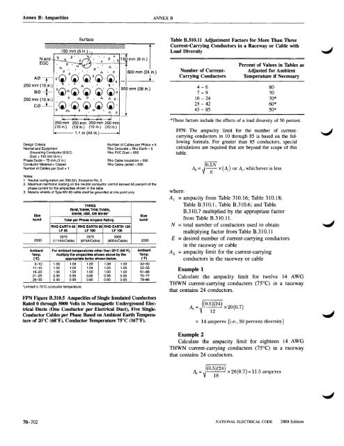
<strong>Annex</strong> B: AmpacitiesANNEX B~N andEGCSurface150 mm (6 in.) ~6. 0 ' ,.~', (J, 0 ,6.-----r,.o ,~ 150 mm (6 in.)A " (J \, [J [l ." A \ [J 600 mm (24 in.A0~ 0(1) (I),CI)0(l),(I)~ L250 mm (10 in.) , '1 • LJ. A ... I '1B0+I0(1)6.(1),(1) (I)'(I)~250 mm (10 . 0 .c.. 0 , 6. 6. 0,in.)C0 -L:. ~ (I)~ (1)0 (I), 0(1), (I)', 0 0250mm 250 mm 250 mm 250 mm(10 in.) (10 in.) (10 in.) (10 in.)1.1 m (44 in.)-jmm (38 ;,.)Design Criteria Number of Cables per Phase = 5Neutral and Equipment Rho Concrete = Rho Earth - 5Grounding Conductor (EGC) Rho PVC Duct = 650Duct = 150 mm (6 in.)Phase Ducts =75 mm (3 in.) Rho Cable Insulation =500Conductor Material = Copper Rho Cable Jacket = 650Number of Cables per Duct = 1Notes:1. Neutral configuretion per 300.5(1), Exception NO.2.2. Maximum harmonic loading on the neutral conductor cannot exceed 50 percent of thephase current <strong>for</strong> the ampacities shown in the table.3. Metallic shields of Type MV-90 cable shall be grounded at one point only.TYPESRHW, THHW, THW, THWN,SizeXHHW, USE, OR MV·90'Sizekcmll Totel per Phase Ampere Rating kcmllRHO EARTH 60 RHO EARTH 90 RHO EARTH 120LF50 LF 100 LF 1005575 3375 30002000 (1115NCable) (675NCable) (600NCable) 2000AmbiantTemp.(OC)For ambient temperatures other than 20"C (68"F),multiply the ampacltles shown above by theappropriate factor shown below.6-10 1.09 1.09 1.09 1.09 1.0911-15 1.04 1.04 1.04 1.04 1.0416-20 1.00 1.00 1.00 1.00 1.0021-25 0.95 0.95 0.95 0.95 0.9526-30 0.90 0.90 0.90 0.90 0.90'Limited to 75"C conductor temperature.AmbientTemp.("F)43-5052-5961-6870-777!Hl6FPN Figure B.310.5 Ampacities of Single Insulated ConductorsRated 0 through 5000 Volts in Nonmagnetic Underground ElectricalDucts (One Conductor per Electrical Duct), Five SingleConductor Cables per Phase Based on Ambient Earth Temperatureof 20°C (68°F), Conductor Temperature 75°C (167°F).Table B.310.11 Adjustment Factors <strong>for</strong> More Than ThreeCurrent-Carrying Conductors in a Raceway or Cable withLoad DiversityNumber of CurrentCarrying ConductorsPercent of Values in Tables asAdjusted <strong>for</strong> AmbientTemperature if Necessary4-6 807-9 7010 - 24 70*25 - 42 60*43 - 85 50**These factors include the effects of a load diversity of 50 percent.FPN: The ampacity limit <strong>for</strong> the number of currentcarryingconductors in 10 through 85 is based on the following<strong>for</strong>mula. For greater than 85 conductors, specialcalculations are required that are beyond the scope of thistable.~ = JO'~:V x (AI) or AI' whichever is lesswhere:Al =ampacity from Table 310.16; Table 310.18;Table B.31O.1; Table B.3IO.6; and TableB.3IO.7 multiplied by the appropriate factorfrom Table B.310.11.N =total number of conductors used to obtainmultiplying factor from Table B.31O.11E =desired number of current-carrying conductorsin the raceway or cableAz =ampacity limit <strong>for</strong> the current-carryingconductors in the raceway or cableExample 1Calculate the ampacity limit <strong>for</strong> twelve 14 AWGTHWN current-carrying conductors (75°C) in a racewaythat contains 24 conductors.~ = (0.5)(24) x20(0.7)12= 14 amperes (i.e.• 50 percent diversity)Example 2Calculate the ampacity limit <strong>for</strong> eighteen 14 AWGTHWN current-carrying conductors (75°C) in a racewaythat contains 24 conductors.(0.5)(24)~ = ./-'-----'-'---'- x 20(0.7) = u.s amperes1870-702NATIONAL ELECTRICAL CODE2008 Edition