Annex B Application Information for Ampacity Calculation
Annex B Application Information for Ampacity Calculation
Annex B Application Information for Ampacity Calculation

Create successful ePaper yourself
Turn your PDF publications into a flip-book with our unique Google optimized e-Paper software.
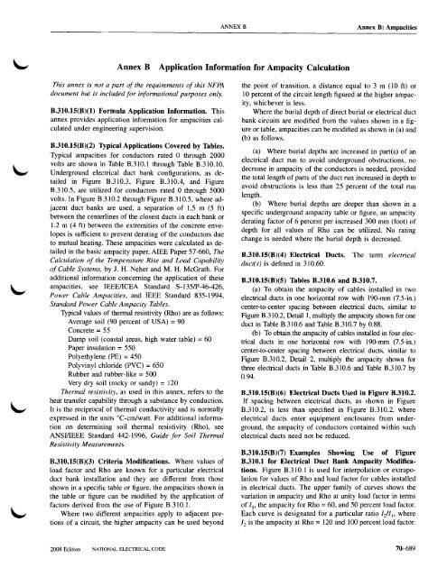
ANNEX B<strong>Annex</strong> B: Ampacities<strong>Annex</strong> B <strong>Application</strong> <strong>In<strong>for</strong>mation</strong> <strong>for</strong> <strong>Ampacity</strong> <strong>Calculation</strong>This annex is not a part of the requirements of this NFPAdocument but is included <strong>for</strong> in<strong>for</strong>mational purposes only.B.310.15(B)(I) Formula <strong>Application</strong> <strong>In<strong>for</strong>mation</strong>. Thisannex provides application in<strong>for</strong>mation <strong>for</strong> ampacities calculatedunder engineering supervision.B.310.15(B)(2) Typical <strong>Application</strong>s Covered by Tables.Typical ampacities <strong>for</strong> conductors rated 0 through 2000volts are shown in Table B.3lO.l through Table B.31O.1O.Underground electrical duct bank configurations, as detailedin Figure B.31O.3, Figure B.31O.4, and FigureB.310.5, are utilized <strong>for</strong> conductors rated 0 through 5000volts. In Figure B.31O.2 through Figure B.31O.5, where adjacentduct banks are used, a separation of 1.5 m (5 ft)between the centerlines of the closest ducts in each bank or1.2 m (4 ft) between the extremities of the concrete envelopesis sufficient to prevent derating of the conductors dueto mutual heating. These ampacities were calculated as detailedin the basic ampacity paper, AlEE Paper 57-660, The<strong>Calculation</strong> of the Temperature Rise and Load Capabilityof Cable Systems, by J. H. Neher and M. H. McGrath. Foradditional in<strong>for</strong>mation concerning the application of theseampacities, see IEEE/lCEA Standard S-135IP-46-426,Power Cable Ampacities, and IEEE Standard 835-1994,Standard Power Cable <strong>Ampacity</strong> Tables.Typical values of thermal resistivity (Rho) are as follows:Average soil (90 percent of USA) =90Concrete =55Damp soil (coastal areas, high water table) =60Paper insulation =550Polyethylene (PE) =450Polyvinyl chloride (PVC) =650Rubber and rubber-like = 500Very dry soil (rocky or sandy) = 120Thermal resistivity, as used in this annex, refers to theheat transfer capability through a substance by conduction.It is the reciprocal of thermal conductivity and is normallyexpressed in the units DC-em/watt. For additional in<strong>for</strong>mationon determining soil thermal resistivity (Rho), seeANSIIIEEE Standard 442-1996, Guide <strong>for</strong> Soil ThermalResistivity Measurements.B.310.15(B)(3) Criteria Modifications. Where values ofload factor and Rho are known <strong>for</strong> a particular electricalduct bank installation and they are different from thoseshown in a specific table or figure, the ampacities shown inthe table or figure can be modified by the application offactors derived from the use of Figure B.31O.1.Where two different ampacities apply to adjacent portionsof a circuit, the higher ampacity can be used beyondthe point of transition, a distance equal to 3 m (lOft) or10 percent of the circuit length figured at the higher ampacity,whichever is less.Where the burial depth of direct burial or electrical ductbank circuits are modified from the values shown in a figureor table, ampacities can be modified as shown in (a) and(b) as follows.(a) Where burial depths are increased in part(s) of anelectrical duct run to avoid underground obstructions, nodecrease in ampacity of the conductors is needed, providedthe total length of parts of the duct run increased in depth toavoid obstructions is less than 25 percent of the total runlength.(b) Where burial depths are deeper than shown in aspecific underground ampacity table or figure, an ampacityderating factor of 6 percent per increased 300 mm (foot) ofdepth <strong>for</strong> all values of Rho can be utilized. No ratingchange is needed where the burial depth is decreased.B.310.15(B)(4) Electrical Ducts.duct(s) is defined in 310.60.The term electricalB.310.15(B)(5) Tables B.310.6 and B.310.7.(a) To obtain the ampacity of cables installed in twoelectrical ducts in one horizontal row with 190-mm (7.5-in.)center-to-center spacing between electrical ducts, similar toFigure B.31O.2, Detail I, multiply the ampacity shown <strong>for</strong> oneduct in Table B.31O.6 and Table B.31O.7 by 0.88.(b) To obtain the ampacity of cables installed in four electricalducts in one horizontal row with 190-mm (7.5-in.)center-to-center spacing between electrical ducts, similar toFigure B.31O.2, Detail 2, multiply the ampacity shown <strong>for</strong>three electrical ducts in Table B.31O.6 and Table B.310.7 by0.94.B.310.15(B)(6) Electrical Ducts Used in Figure B.310.2.If spacing between electrical ducts, as shown in FigureB.31O.2, is less than specified in Figure B.31O.2, whereelectrical ducts enter equipment enclosures from underground,the ampacity of conductors contained within suchelectrical ducts need not be reduced.B.310.15(B)(7) Examples Showing Use of FigureB.310.1 <strong>for</strong> Electrical Duct Bank <strong>Ampacity</strong> Modifications.Figure B.310.1 is used <strong>for</strong> interpolation or extrapolation<strong>for</strong> values of Rho and load factor <strong>for</strong> cables installedin electrical ducts. The upper family of curves shows thevariation in ampacity and Rho at unity load factor in termsof II' the ampacity <strong>for</strong> Rho =60, and 50 percent load factor.Each curve is designated <strong>for</strong> a particular ratio IiI" where1 2is the ampacity at Rho = 120 and 100 percent load factor.2008 Edition NATIONAL ELECfRICAL CODE70-689
<strong>Annex</strong> B: AmpacitiesANNEXBThe lower family of curves shows the relationship betweenRho and load factor that will give substantially thesame ampacity as the indicated value of Rho at 100 percentload factor.As an example, to find the ampacity of a 500 kcmilcopper cable circuit <strong>for</strong> six electrical ducts as shown inTable B.31O.5: At the Rho = 60, LF = 50, I} =583; <strong>for</strong> Rho= 120 and LF = 100, 1 2 = 400. The ratio IiII = 0.686.Locate Rho = 90 at the bottom of the chart and follow the90 Rho line to the intersection with 100 percent load factorwhere the equivalent Rho = 90. Then follow the 90 Rholine to Iillratio of 0.686 where F = 0.74. The desiredampacity = 0.74 x 583 = 431, which agrees with the table<strong>for</strong> Rho =90, LF = 100.To determine the ampacity <strong>for</strong> the same circuit whereRho =80 and LF =75, using Figure B.31 0.1, the equivalentRho = 43, F = 0.855, and the desired ampacity = 0.855x 583 = 498 amperes. Values <strong>for</strong> using Figure B.310.1 arefound in the electrical duct bank ampacity tables of this annex.Where the load factor is less than 100 percent and canbe verified by measurement or calculation, the ampacity ofelectrical duct bank installations can be modified as shown.Different values of Rho can be accommodated in the samemanner.Table B.310.1 Ampacities of Two or Three Insulated Conductors, Rated 0 Through 2000 Volts,Within an Overall Covering (Multiconductor Cable), in Raceway in Free AirBased on Ambient Air Temperature of 30°C (86°F)Temperature Rating of Conductor. (See Table 310.13.)60°C (140°F) 7SoC (167°F) 90°C (194°F) 60°C (140°F) 7SoC (167°F) 90°C (194°F)Types TW, UFTypes RHW,THHW,THW,THWN,XHHW,ZWTypes THHN,THHW,THW-2,THWN·2,RHH,RWH·2,USE·2,XHHW,XHHW-2,ZW-2TypeTWTypes RHW,THHW, THW,THWN,XHHWTypes THHN,THHW,THW·2,THWN·2,RHH,RWH·2,USE·2,XHHW,XHHW-2,ZW-2Size (AWG orkcmil)COPPERALUMINUM OR COPPER-CLADALUMINUMSize (AWG orkcmil)141210816*20*27*3618*24*33*4321*27*36*48-16*21*28-18*25*33-21*28*3714121086432I48667688102587990105121658910211913738515969804561708395516979931066432I1102/03/04/0121138158187145166189223163186214253941081241471131291471761271461671971102/03/04/025030035040050020523425527431524528130532837827631734537142716018520221825419222124226130321725027329534225030035040050070-690NATIONAL ELECTRICAL CODE2008 Edition
ANNEX B<strong>Annex</strong> B: AmpacitiesTable B.310.1ContinuedTemperature Rating of Conductor. (See Table 310.13.)60°C (l40°F) 7SoC (167°F) 90°C (194°F) 60°C (140°F) 7SoC (167°F) 90°C (194°F)Types THHN,TypesTHHN,THHW,THHW,THW·2,THW-2,THWN-2,THWN·2,RHH,RHH,Types RHW, RWH·2,RWH-2,THHW, USE-2, Types RHW, USE·2,THW, XHHW, THHW,THW, XHHW,THWN, XHHW-2, THWN, XHHW-2,Types TW, UF XHHW,ZW ZW-2 Type TW XHHW ZW-2Size (AWG or ALUMINUM OR COPPER-CLAD Size (AWG orkcmil)COPPERALUMINUMkcmil)I600 343 413 468 279 335 378 600700 376 452 514 310 371 420700750 387 466529 321 384 435 750800 397479 543 331 397450800900 415 500 570 350421 477 9001000 448 542 617 382 460 5211000Correction FactorsAmbient For ambient temperatures other than 30°C (86°F), multiply the ampacities shown above by the AmbientTemp. (0C) appropriate factor shown below. Temp. eF)21-25 1.08 1.05 1.04 1.081.05 1.04 70-7726-30 1.00 1.00 1.001.00 1.001.00 79-8631-350.91 0.94 0.96 0.91 0.940.96 88-9536-400.820.88 0.91 0.82 0.88 0.91 97-10441-450.71 0.82 0.87 0.710.82 0.87 106-11346-50 0.58 0.750.82 0.58 0.750.82 115-12251-55 0.410.67 0.76 0.410.67 0.76 124-13156-60- 0.58 0.71- 0.58 0.71 133-14061-70 -0.330.58 - 0.330.58 142-15871-80 - -0.41 -- 0.41 160-176*Unless otherwise specifically permitted elsewhere in this Code, the overcurrent protection <strong>for</strong> theseconductor types shall not exceed 15 amperes <strong>for</strong> 14 AWG, 20 amperes <strong>for</strong> 12 AWG, and 30 amperes <strong>for</strong>10 AWG copper; or 15 amperes <strong>for</strong> 12 AWG and 25 AWG amperes <strong>for</strong> 10 AWG aluminum andcopper-clad aluminum.2008 Edition NATIONAL ELECTRICAL CODE 70--691
<strong>Annex</strong> B: AmpacitiesANNEXBTable B.310.3 Ampacities of Multiconductor Cables with Not More Than Three Insulated Conductors,Rated 0 Through 2000 Volts, in Free Air Based on Ambient Air Temperature of 40°C (104°F)(For Types TC, MC, MI, UF, and USE Cables)Temperature Rating of Conductor. (See Table 310.13.)Size (AWGor kcmil)6O°C(140°F)7S o C 8S o C(167°F) (18S 0 F)COPPER90°C(194°F)60°C 7S o C 8S o C 9O°C(140°F) (167°F) (18S 0 F) (194°F)ALUMINUM OR COPPER·CLAD ALUMINUMSize (AWGor kcmil)18161412108--18*21*28*39--21*28*36*50--24*30*41*5611*16*25*32*43*59---18*21*30---21*28*39---24*30*44---25*32*4618161412108643215269819210768891041181387510011613215479104121138161415463728453708192108597891103120618195108126643211/02/03/04/0124143165190160184213245178206238274186215249287971111291491251441661921391601852141451681942241/02/03/04/025030035040050021223726128132127430633736341630534137740646532035739442548716618620522225521424026528733023926829631736825028030933438525030035040050060070075080090010003543874044154384614595025235395706015135625866046396745385896156336707072843063283393623853684054244394694994104624734905145584294734955135485846007007508009001000Correction FactorsAmbient For ambient temperatures other than 40°C (104°F), AmbientTemp. multiply the ampacities shown above Temp.("C) by the appropriate factor shown below. (oF)21-25 1.32 1.20 1.15 1.14 1.32 1.20 1.15 1.14 70-7726-30 1.22 1.13 1.11 1.10 1.22 1.13 1.11 1.10 79-8631-35 1.12 1.07 1.05 1.05 1.12 1.07 1.05 1.05 88-9536-40 1.00 1.00 1.00 1.00 1.00 1.00 1.00 1.00 97-10441-45 0.87 0.93 0.94 0.95 0.87 0.93 0.94 0.95 106-11346-50 0.71 0.85 0.88 0.89 0.71 0.85 0.88 0.89 115-12251-55 0.50 0.76 0.82 0.84 0.50 0.76 0.82 0.84 124-13156-60 - 0.65 0.75 0.77 - 0.65 0.75 0.77 133-14061-70 - 0.38 0.58 0.63 - 0.38 0.58 0.63 142-15871-80 - - 0.33 0.44 - - 0.33 0.44 160-176'Unless othelWise specifically permitted elsewhere in this Code, the overcurrent protection <strong>for</strong> these conductortypes shall not exceed 15 amperes <strong>for</strong> 14 AWG, 20 amperes <strong>for</strong> 12 AWG, and 30 amperes <strong>for</strong> 10 AWG copper;or 15 amperes <strong>for</strong> 12 AWG and 25 amperes <strong>for</strong> 10 AWG aluminum and copper-clad aluminum.70--692NATIONAL ELECTRICAL CODE2008 Edition
ANNEX B<strong>Annex</strong> B: AmpacitiesTable B.310.5 Ampacities of Single Insulated Conductors, Rated 0 through 2000 Volts, inNonmagnetic Underground Electrical Ducts (One Conductor per Electrical Duct),Based on Ambient Earth Temperature of 20°C (68°F), Electrical Duct Arrangementper Figure B.310.2, Conductor Temperature 7SoC (167°F)Size(kcmil)3 Electrical Ducts(Fig. B.310.2,Detail 2)Types RHW,THHW,THW,THWN,XHHW,USE6 Electrical Ducts 9 Electrical Ducts 3 Electrical Ducts 6 Electrical Ducts 9 Electrical Ducts(Fig. B.310.2, (Fig. B.310.2, (Fig. B.310.2, (Fig. B.310.2, (Fig. B.310.2,Detail 3) Detail 4) Detail 2) Detail 3) Detail 4)Types RHW, Types RHW, Types RHW, Types RHW, Types RHW,THHW,THW, THHW,THW, THHW,THW, THHW,THW, THHW,THW,THWN,XHHW, THWN,XHHW, THWN,XHHW, THWN,XHHW, THWN,XHHW,USE USE USE USE USESizeCOPPER ALUMINUM OR COPPER·CLAD ALUMINUM (kcmil)RHO RHO RHO60 90 120LF LF LF50 100 100250 410 344 327350 503 418 396500 624 511 484750 794 640 6031000 936 745 7001250 1055 832 7811500 1160 907 8491750 1250 970 9072000 1332 1027 959RHO RHO RHO RHO RHO RHO RHO RHO RHO RHO RHO RHO RHO RHO RHO60 90 120 60 90 120 60 90 120 60 90 120 60 90 120LF LF LF LF LF LF LF LF LF LF LF LF LF LF LF50 100 100 50 100 100 50 100 100 50 100 100 50 100 100386 295 275 369 270 252 320 269 256 302 230 214 288 211 197 250472 355 330 446 322 299 393 327 310 369 277 258 350 252 235 350583 431 400 545 387 360 489 401 379 457 337 313 430 305 284 500736 534 494 674 469 434 626 505 475 581 421 389 538 375 347 750864 617 570 776 533 493 744 593 557 687 491 453 629 432 399 1000970 686 632 854 581 536 848 668 627 I 779 551 508 703 478 441 12501063 744 685 918 619 571 941 736 689 863 604 556 767 517 477 15001142 793 729 975 651 599 1026 796 745 I 937 651 598 823 550 507 17501213 836 768 1030 683 628 1103 850 794 1005 693 636 877 581 535 2000AmbientTemp.(0C)Correction FactorsAmbientTemp.(OF)6-10 1.0911-15 1.0416-20 1.0021-25 0.9526-30 0.901.09 1.091.09 1.09 1.09 43-501.041.04 1.041.04 1.04 52-591.00 1.00 1.00 1.001.00 61~80.95 0.95 0.950.95 0.95 70-77I 0.90 0.90 0.900.900.90 79-86i2008 Edition NATIONAL ELECTRICAL CODE 70-693
<strong>Annex</strong> B: AmpacitiesANNEX BTable B.310.6 Ampacities of Three Insulated Conductors, Itated 0 through 2000 Volts,Within an Overall Covering (Three-Conductor Cable) in Underground Electrical Ducts(One Cable per Electrical Duct) Based on Ambient Earth Temperature of 20°C (68°F),Electrical Duct Arrangement per Figure B.310.2, Conductor Temperature 7SoC (167°F)1 Electrical Duct 3 Electrical Ducts 6 Electrical Ducts 1 Electrical Duct 3 Electrical Ducts 6 Electrical Ducts(Fig. B.310.2, (Fig. B.310.2, (Fig. B.310.2, (Fig. B.310.2, (Fig. B.310.2, (Fig. B.31O.2,Detail 1) Detail 2) Detail 3) Detail 1) Detail 2) Detail 3)Size(AWG orkcmil)Types RHW, Types RHW, Types RHW, Types RHW, Types RHW, Types RHW,THHW,THW, THHW,THW, THHW,THW, THHW,THW, THHW,THW, THHW,THW,THWN,XHHW, THWN,XHHW, THWN,XHHW, THWN,XHHW, THWN,XHHW, THWN,XHHW,USE USE USE USE USE USECOPPERALUMINUM OR COPPER·CLAD ALUMINUMRHO RHO RHO RHO RHO RHO RHO RHO RHO RHO RHO RHO RHO RHO RHO RHO RHO RHO60 90 120 60 90 120 60 90 120 60 90 120 60 90 120 60 90 120LF LF LF LF LF LF LF LF LF LF LF LF LF LF LF LF LF LF50 100 100 50 100 100 50 100 100 50 100 100 50 100 100 50 100 100Size(AWG orkcmil)8 58 54 53 56 48 46 53 42 39 45 42 41 43 37 36 41 32 30 86 77 71 69 74 63 60 70 54 51 60 55 54 57 49 47 54 42 39 64 101 93 91 96 81 77 91 69 65 78 72 71 75 63 60 71 54 51 42 132 121 ]]8 126 105 100 ]]9 89 83 103 94 92 98 82 78 92 70 65 21 154 140 136 146 121 114 137 102 95 120 109 106 ]]4 94 89 107 79 74 11/02/03/04/02503505007501000177 160 156 168 137 130 157 116 107 138 125 122 131 107 101 122 90 84203 183 178 192 156 147 179 131 121 158 143 139 150 122 115 140 102 95233 210 204 221 178 158 205 148 137 182 164 159 172 139 131 160 116 107268 240 232 253 202 190 234 168 155 209 187 182 198 158 \49 183 131 121297 265 256 280 222 209 258 184 169 233 207 201 219 174 163 I 202 144 132363 321 310 340 267 250 312 219 202 285 252 244 267 209 196 245 172 158444 389 375 414 320 299 377 261 240 352 308 297 328 254 237 299 207 190552 478 459 5]] 388 362 462 314 288 446 386 372 413 314 293 'I 374 254 233628 539 518 579 435 405 522 351 321 521 447 430 480 361 336 433 291 266I/O2/03/04/02503505007501000AmbientAmbientTemp. Correction Factors Temp.CC)CF)6-10 1.09 1.09 1.09 1.09 1.09 1.09 43-5011-15 1.04 1.04 1.04 1.04 1.04 1.04 52-5916-20 1.00 1.00 1.00 1.00 1.00 1.00 61---6821-25 0.95 0.95 0.95 0.95 0.95 0.95 70-7726-30 0.90 0.90 0.90 0.90 0.90 0.90 79-8670-694NATIONAL ELECTRICAL CODE2008 Edition
ANNEX B<strong>Annex</strong> B: AmpacitiesTable B.310.7 Ampacities of Three Single Insulated Conductors, Rated 0 Through 2000 Volts,in Underground Electrical Ducts (Three Conductors per Electrical Duct)Based on Ambient Earth Temperature of 20°C (68°F), Electrical Duct Arrangementper Figure B.310.2, Conductor Temperature 7SoC (167°F)1 Electrical Duct 3 Electrical Ducts(Fig. 8.310.2, (Fig. 8.310.2,Detail 1) Detail 2)6 Electrical Ducts 1 1 Electrical Duct 3 Electrical Ducts(Fig. 8.310.2, (Fig. 8.310.2, (Fig. 8.310.2,Detail 3) Detail 1) Detail 2)6 Electrical Ducts(Fig. 8.310.2,Detail 3)Size(AWG orkcmil)Types RHW,THHW,THW,THWN,XHHW,USETypes RHW,THHW,THW,THWN,XHHW,USECOPPERTypes RHW, Types RHW, 1 Types RHW,THHW,THW, THHW, THW, THHW, THW,THWN,XHHW, THWN, XHHW, I THWN, XHHW,USEUSEUSETypes RHW,THHW,THW,THWN,XHHW,USEALUMINUM OR COPPER·CLAD ALUMINUMSize(AWG orkcmil)86432I 1 171RHO RHO RHO RHO RHO RHO60 90 120 60 90 120LF LF LF LF LF LF50 100 100 50 100 10063 58 57 61 51 4984 77 75 80 67 63111 100 98 105 86 81129 116 113 122 99 94147 132 128 139 112 106153 148 161 128 121RHO RHO RHO60 90 120LF LF LF50 100 100RHO RHO RHO60 90 120LF LF LF50 100 100RHO60LF50RHO90LF100RHO120LF10057 44 41 49 45 44 47 40 3875 56 53 66 60 58 63 52 4998 73 671 86 78 76 79 67 63113 83 77 101 91 89 83 77 73129 93 86 I 115 103 100 108 87 82149 106 98 133 119 115 1 126 100 94RHO RHO RHO60 90 120LF LF LF50 100 10045 34 32 859 44 41 677 57 52 484 65 60 3101 73 67 2116 83 77 I1102/03/04/0197226260301175200228263169 185193 212220 1 243253 280146166189215137156177201170194222255121136154175III1261421611153176I 203235136156178205132151172198144165189219114130147168107121138157133 94 87 110151 106 98 2/0173 121 111 3/0199 137 126 4/0250300350400334373409442290321351376279 310308 344337 377361 394236260283302220242264280281310340368192210228243176 I 261192 293209 321223 i 349227252276297218242265284242272296321185204222238172190207220220 150 137 250245 165 151 300266 179 164 350288 191 174 400500600700750503552602632427468509529409 460447 511486 553505 5743413714024173163433713854124574925092732963193302492702913011391446488508338373408425323356389405364408443461270296321334250274297309326 216 197 500365 236 215 600394 255 232 700409 265 241 7508009001000654692730544575605520 597549 628576 659428450472395415435527554581338355372308323338530563597439466494418444471481510538344365385318337355427 273 247450 288 261475 304 2768009001000AmbientTemp.(OC)Correction FactorsAmbientTemp.("F)6-1011-1516-2021-2526-301.091.041.000.950.901.091.041.000.950.901.091.041.000.950.901.091.041.000.950.901.091.041.000.950.901.09 43-501.04 52-591.00 61~80.95 70--770.90 79-862008 Edition NATIONAL ELECTRICAL CODE 70-695
<strong>Annex</strong> B: AmpacitiesANNEXBTable B.310.8 Ampacities of Two or Three Insulated Conductors, Rated 0 Through 2000 Volts,Cabled Within an Overall (Two- or Three-Conductor) Covering, Directly Buried in Earth,Based on Ambient Earth Temperature of 20°C (68°F), Arrangement per Figure B.310.2,100 Percent Load Factor, Thermal Resistance (Rho) of 901 Cable (Fig. B.310.2, 2 Cables (Fig. B.310.2, 1 Cable (Fig. B.310.2, 2 Cables (Fig. B.310.2,Detail 5) Detail 6) Detail 5) Detail 6)60°C 75°C 60°C 75°C 60°C 75°C 60°C 7SoC(140°F) (167°F) (140°F) (167°F) (140°F) (167°F) (140°F) (167°F)TYPESTYPESRHW, RHW, RHW, RHW,THHW, THHW, THHW, THHW,THW, THW, THW, THW,THWN, THWN, THWN, THWN,XHHW, XHHW, XHHW, XHHW,UF USE UF USE UF USE UF USESize (AWGSize (AWGor kcmil) COPPER ALUMINUM OR COPPER-CLAD ALUMINUM or kcmil)8 64 75 60 70 51 59 47 55 86 85 100 81 95 68 75 60 70 64 107 125 100 117 83 97 78 91 42 137 161 128 150 107 126 110 117 2I 155 182 145 170 121 142 113 132 1I/O 177 208 165 193 138 162 129 151 I/O2/0 201 236 188 220 157 184 146 171 2/03/0 229 269 213 250 179 210 166 195 3/04/0 259 304 241 282 203 238 188 220 4/0250 - 333 - 308 - 261 - 241 250350 - 401 - 370 - 315 - 290 350500 - 481 - 442 - 381 - 350 500750 - 585 - 535 - 473 - 433 7501000 - 657 - 600 - 545 - 497 1000AmbientAmbientTemp. Correction Factors Temp.(0C)eF)6-10 1.12 1.09 1.12 1.09 1.12 1.09 1.12 1.09 43-5011-15 1.06 1.04 1.06 1.04 1.06 1.04 1.06 1.04 52-5916-20 1.00 1.00 1.00 1.00 1.00 1.00 1.00 1.00 61--6821-25 0.94 0.95 0.94 0.95 0.94 0.95 0.94 0.95 70-7726-30 0.87 0.90 0.87 0.90 0.87 0.90 0.87 0.90 79-86Note: For ampacities of Type UF cable in underground electrical ducts, multiply the ampacities shown in thetable by 0.74.70--696NATIONAL ELECTRICAL CODE2008 Edition
ANNEX B<strong>Annex</strong> 8: AmpacitiesTable 8.310.9 Ampacities of Three Triplexed Single Insulated Conductors,Rated 0 Through 2000 Volts, Directly 8uried in Earth 8ased on Ambient EarthTemperature of 20°C (68°F), Arrangement per Figure 8.310.2,100 Percent Load Factor, Thermal Resistance (Rho) of 90See Fig. 8.310.2,Detail 760°C 7S0C(l40°F) (167°F)See Fig. 8.310.2, See Fig. 8.310.2, See Fig. 8.310.2,Detail 8 Detail 7Detail 860°C 7S0C 60°C 7S0C 60°C 7S0C(140°F) (167°F) (140°F) (167°F) (140°F) (167°F)TYPESTYPESUF USE UF USE UF USE UF USESize (AWG f----...J.---------L----L-----+-------'------'------'------1 Size (AWGor kcmil) COPPER ALUMINUM OR COPPER·CLAD ALUMINUM or kcmil)864217291119153173841071391792036684109140159779912816418655729211913565841081391585166851091246077100128145864211/02/03/04/01972232542892312622983391812052322632122402723081541751992261802052332651411591812061651872122411/02/03/04/025035050075010003704455366547443364034835876652893494245256082633163824715442503505007501000AmbientTemp.(OC)Correction FactorsAmbientTemp.(OF)6-1011-1516-2021-2526-301.l21.061.000.940.871.091.041.000.950.901.121.061.000.940.871.091.041.000.950.901.121.061.000.940.871.091.041.000.950.901.121.061.000.940.871.091.041.000.950.9043-5052-5961--{i870-7779-862008 Edition NATIONAL ELECTRICAL CODE 70--fJ97
<strong>Annex</strong> B: AmpacitiesANNEX BTable B.310.10 Ampacities of Three Single Insulated Conductors, Rated 0 Through 2000 Volts,Directly Buried in Earth Based on Ambient Earth Temperature of 20°C (68°F),Arrangement per Figure B.310.2, 100 Percent Load Factor,Thermal Resistance (Rho) of 90See Fig. B.310.2, See Fig. B.310.2, See Fig. B.310.2, See Fig. B.31O.2,Detail 9 Detail 10 Detail 9 Detail 1060°C 7SoC 60°C 7SoC 60°C 7SoC 60°C 7SoC(140°F) (167°F) (140°F) (167°F) (140°F) (167°F) (140°F) (167°F)TYPESTYPESUF USE UF USE UF USE UF USESize (AWGSize (AWGor kcmil) COPPER ALUMINUM OR COPPER-CI,AD ALUMINUM or kcmil)8 84 98 78 92 66 77 61 72 86 107 126 101 118 84 98 78 92 64 139 163 130 152 108 127 101 118 42 178 209 165 194 139 163 129 151 2I 201 236 187 219 157 184 146 171 11/0 230 270 212 249 179 210 165 194 1/02/0 261 306 241 283 204 239 188 220 2/03/0 297 348 274 321 232 272 213 250 3/04/0 336 394 309 362 262 307 241 283 4/0250 - 429 - 394 - 335 - 308 250350 - 516 - 474 - 403 - 370 350500 - 626 - 572 - 490 - 448 500750 - 767 - 700 - 605 - 552 7501000 - 887 - 808 - 706 - 642 10001250 - 979 - 891 - 787 - 716 12501500 - 1063 - 965 - 862 - 783 15001750 - 1133 - 1027 - 930 - 843 17502000 - 1195 - 1082 - 990 - 897 2000AmbientTemp.eClCorrection FactorsAmbientTemp.(OF)6-10 1.12 1.09 1.12 1.09 1.12 1.09 1.12 1.09 43-5011-15 1.06 1.04 1.06 1.04 1.06 1.04 1.06 1.04 52-5916-20 1.00 1.00 1.00 1.00 1.00 1.00 1.00 1.00 61-6821-25 0.94 0.95 0.94 0.95 0.94 0.95 0.94 0.95 70-7726-30 0.87 0.90 0.87 0.90 0.87 0.90 0.87 0.90 79-8670-698NATIONAL ELECTRICAL CODE2008 Edition
ANNEX B<strong>Annex</strong> B: Ampacities\-.l.L.1.151.101.051.000.950.900.850.800.750.700.650.600.550.500.450.40100959085807570656055504540350.95~ ::::::: r- I-'I \:~ :'-.. ........ .:::::: r-r- r---I- o.sor\'" I'-i"- r---. - --r-r-!!.5I'" 1'-" r----.. r-- -- t-.... r-..... :-r-r-0.80t-.... "'-., ,.......-.- r- 1--0.75r- r-I'" " -. -.I'.....-I"-r-.0.70 -:-r-I-i"--. ....... -.r--.. I'--. l"- I"- 0.61 r- r-I ""'-- !'--.. I'--. r-. 0.60 -:-- I-:......... r-..... I'--. '-...9.55- :--I-Ir- _o.50 --:-Ir-I-10 20 30 40 50 60 70 80 90 100 110120130140150160170180190200I-\ 1\ 1\ 1\\1\ 1\ [\. [\."""'1"1"'1"""l.'-- """ "'-., "'-., .""' ~\ \ \ \ \~'" "' "" '" 't-.... " .......... ~ t" I'--.\ \ I~ '\ '\'" I" " I'.... ........... .......... 'I'-..r---.\ \ \ \ ~1""" '""" " i"--. .......... !'--.. r---.'11\ 1"\ ~ "' "f'-" "~ ~ ........ ,....... I'--. r-:I'--.\ ~'\i'.. """ f'-... '~ ""' ......... -. r----.\ \ \ [\. fi'.. " i'-.. '~ ......... , ......... r----..1\ \" I........ ........ -.r--.."" '" "'"......... r--. r-I' ~ " ~........ ........ I'--.t-.\ ..........." '!'--.. r-- r--t-..... .......... r--.'"-- -.I- I-... r----.."I'--.t-. I- I-~...r---......... l"I- 'r-- I:::::--30o 10 20 30 40 50 6 70 80 90 100110120130140150160170180190200RHOFigure 8.310.1 Interpolation Chart <strong>for</strong> Cables in a Duct Bank 1 1= ampacity <strong>for</strong>Rho = 60, 50 LF; 1 2 = ampacity <strong>for</strong> Rho = 120, 100 LF ( load factor); desired ampacity = F )( I ..2008 Edition NATIONAL ELECTRICAL CODE 70-699
<strong>Annex</strong> B: AmpacitiesANNEX BDetail 1290 mm x 290 mm(11.5 in. x 11.5 in.)Electrical duct bankOne electrical duct.5LI)t:.ESl190 mm (7.5 in.)Detail 2475 mm x 475 mm(19 in. x 19 in.)Electrical duct bankThree electrical ductsor' , . ., , 'Il2WJ190 mm 190 mm(7.5 in.) (7.5 in.)675 mm x 290 mm(27 in. x 11.5 in.)Electrical duct bankThree electrical ducts600mm(24 in.)•DetailS Detail 6Buried 3 Buried 3conductorconductorcablecables190 mm 190 mm(7.rt1n .)1E--,.E.!:eLI)~r:::.190 mm (7.5 in.)Detail 3475 mm x 675 mm(19 in. x 27 in.)Electrical duct bankSix electrical ductsor190 mm 190 mm(7.5 in.) (7.5 in.)•••I ,675 mm x 475 mm(27 in. x 19 in.)Electrical duct bankDetail?Buried triplexedcables (1 circuit)E--,.E.!:eLI)~t::.A'. C(;).:.(;)~,~100 A. "... 0190 mm 190 mm(7.5 in.) (7.5 in.)Detail 4675 mm x 675 mm(27 in. x 27 in.)Electrical duct bankNine electrical ducts.~600mm(24 in.)J.Detail 8Buried triplexedcables (2 circuits)190mm190mm 190mm(7.5 in.) 600mm (7.5 in.) (7.5 in.)(24 in.)Detail 9Buried single-conductorcables (1 circuit)Detail 10Buried single-conductorcables (2 circuits)Note 1: Minimum burial depths to top electrical ducts or cables shall be inaccordance with 300.5. Maximum depth to the top of electrical ductbanks shall be 750 mm (30 in.) and maximum depth to the top ofdirect buried cables shall be 900 mm (36 in.)Note 2: For two and four electrical duct installations with electrical ductsinstalled in a single row, see B.310.15(B)(5).Legend~ Backfill~ (earth or concrete)o Electrical duct• Cable or cablesFigure B.310.2 Cable Installation Dimensions <strong>for</strong> Use withB.310.10.TableB.310.5 Through Table70-700NATIONAL ELECTRICAL CODE2008 Edition
ANNEX B<strong>Annex</strong> B: AmpacitiesSurface150 mm (6 in.)r--------,I-----.-.N and-,--_tl--.,,.J . ..t-"'\ 150 mm (6 in.)EGC-"---..-+-+600 mm (24 in.)A ..a J, []rc;)c;)c;)190 mm (7.5~
<strong>Annex</strong> B: AmpacitiesANNEX B~N andEGCSurface150 mm (6 in.) ~6. 0 ' ,.~', (J, 0 ,6.-----r,.o ,~ 150 mm (6 in.)A " (J \, [J [l ." A \ [J 600 mm (24 in.A0~ 0(1) (I),CI)0(l),(I)~ L250 mm (10 in.) , '1 • LJ. A ... I '1B0+I0(1)6.(1),(1) (I)'(I)~250 mm (10 . 0 .c.. 0 , 6. 6. 0,in.)C0 -L:. ~ (I)~ (1)0 (I), 0(1), (I)', 0 0250mm 250 mm 250 mm 250 mm(10 in.) (10 in.) (10 in.) (10 in.)1.1 m (44 in.)-jmm (38 ;,.)Design Criteria Number of Cables per Phase = 5Neutral and Equipment Rho Concrete = Rho Earth - 5Grounding Conductor (EGC) Rho PVC Duct = 650Duct = 150 mm (6 in.)Phase Ducts =75 mm (3 in.) Rho Cable Insulation =500Conductor Material = Copper Rho Cable Jacket = 650Number of Cables per Duct = 1Notes:1. Neutral configuretion per 300.5(1), Exception NO.2.2. Maximum harmonic loading on the neutral conductor cannot exceed 50 percent of thephase current <strong>for</strong> the ampacities shown in the table.3. Metallic shields of Type MV-90 cable shall be grounded at one point only.TYPESRHW, THHW, THW, THWN,SizeXHHW, USE, OR MV·90'Sizekcmll Totel per Phase Ampere Rating kcmllRHO EARTH 60 RHO EARTH 90 RHO EARTH 120LF50 LF 100 LF 1005575 3375 30002000 (1115NCable) (675NCable) (600NCable) 2000AmbiantTemp.(OC)For ambient temperatures other than 20"C (68"F),multiply the ampacltles shown above by theappropriate factor shown below.6-10 1.09 1.09 1.09 1.09 1.0911-15 1.04 1.04 1.04 1.04 1.0416-20 1.00 1.00 1.00 1.00 1.0021-25 0.95 0.95 0.95 0.95 0.9526-30 0.90 0.90 0.90 0.90 0.90'Limited to 75"C conductor temperature.AmbientTemp.("F)43-5052-5961-6870-777!Hl6FPN Figure B.310.5 Ampacities of Single Insulated ConductorsRated 0 through 5000 Volts in Nonmagnetic Underground ElectricalDucts (One Conductor per Electrical Duct), Five SingleConductor Cables per Phase Based on Ambient Earth Temperatureof 20°C (68°F), Conductor Temperature 75°C (167°F).Table B.310.11 Adjustment Factors <strong>for</strong> More Than ThreeCurrent-Carrying Conductors in a Raceway or Cable withLoad DiversityNumber of CurrentCarrying ConductorsPercent of Values in Tables asAdjusted <strong>for</strong> AmbientTemperature if Necessary4-6 807-9 7010 - 24 70*25 - 42 60*43 - 85 50**These factors include the effects of a load diversity of 50 percent.FPN: The ampacity limit <strong>for</strong> the number of currentcarryingconductors in 10 through 85 is based on the following<strong>for</strong>mula. For greater than 85 conductors, specialcalculations are required that are beyond the scope of thistable.~ = JO'~:V x (AI) or AI' whichever is lesswhere:Al =ampacity from Table 310.16; Table 310.18;Table B.31O.1; Table B.3IO.6; and TableB.3IO.7 multiplied by the appropriate factorfrom Table B.310.11.N =total number of conductors used to obtainmultiplying factor from Table B.31O.11E =desired number of current-carrying conductorsin the raceway or cableAz =ampacity limit <strong>for</strong> the current-carryingconductors in the raceway or cableExample 1Calculate the ampacity limit <strong>for</strong> twelve 14 AWGTHWN current-carrying conductors (75°C) in a racewaythat contains 24 conductors.~ = (0.5)(24) x20(0.7)12= 14 amperes (i.e.• 50 percent diversity)Example 2Calculate the ampacity limit <strong>for</strong> eighteen 14 AWGTHWN current-carrying conductors (75°C) in a racewaythat contains 24 conductors.(0.5)(24)~ = ./-'-----'-'---'- x 20(0.7) = u.s amperes1870-702NATIONAL ELECTRICAL CODE2008 Edition