Chapter 3 Wiring Methods and Materials
Chapter 3 Wiring Methods and Materials
Chapter 3 Wiring Methods and Materials

Create successful ePaper yourself
Turn your PDF publications into a flip-book with our unique Google optimized e-Paper software.
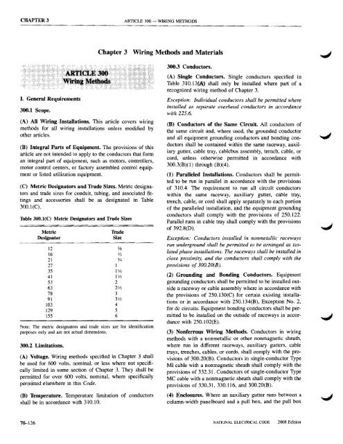
CHAPTER 3 ARTICLE 300 - WIRING METHODS<br />
<strong>Chapter</strong> 3 <strong>Wiring</strong> <strong>Methods</strong> <strong>and</strong> <strong>Materials</strong><br />
I. General Requirements<br />
30tU Scope.<br />
(A) All <strong>Wiring</strong> Installations. This article covers wlflng<br />
methods for all wiring installations unless modified by<br />
other articles.<br />
(B) Integral Parts of Equipment. The provisions of this<br />
article are not intended to apply to the conductors that form<br />
an integral part of equipment, such as motors, controllers,<br />
motor control centers, or factory assembled control equipment<br />
or listed utilization equipment.<br />
(C) Metric Designators <strong>and</strong> Trade Sizes. Metric designators<br />
<strong>and</strong> trade sizes for conduit, tubing, <strong>and</strong> associated fittings<br />
<strong>and</strong> accessories shall be as designated in Table<br />
300. 1(C).<br />
Table 300.1(C) Metric Designators <strong>and</strong> Trade Sizes<br />
Metric<br />
Designator<br />
Trade<br />
Size<br />
12 3/8<br />
16 V2<br />
21 %<br />
27 1<br />
35 P/4<br />
41 1V2<br />
53 2<br />
63 2V2<br />
78 3<br />
91 3Y2<br />
103 4<br />
129 5<br />
155 6<br />
Note: The metric designators <strong>and</strong> trade sizes are for identification<br />
purposes only <strong>and</strong> are not actual dimensions.<br />
300.2 Limitations.<br />
(A) Voltage. <strong>Wiring</strong> methods specified in <strong>Chapter</strong> 3 shall<br />
be used for 600 volts, nominal, or less where not specifically<br />
limited in some section of <strong>Chapter</strong> 3. They shall be<br />
permitted for over 600 volts, nominal, where specifically<br />
permitted elsewhere in this Code.<br />
(B) Temperature. Temperature limitation of conductors<br />
shall be in accordance with 310.10.<br />
300.3 Conductors.<br />
(A) Single Conductors. Single conductors specified in<br />
Table 31O.13f~) shall only be installed where part of a<br />
recognized wiring method of <strong>Chapter</strong> 3.<br />
Exception: Individual conductors shall be permitted where<br />
installed as separate overhead conductors in accordance<br />
with 225.6.<br />
(B) Conductors of the Same Circuit. All conductors of<br />
the same circuit <strong>and</strong>, where used, the grounded conductor<br />
<strong>and</strong> all equipment grounding conductors <strong>and</strong> bonding conductors<br />
shall be contained within the same raceway, auxiliary<br />
gutter, cable tray, cablebus assembly, trench, cable, or<br />
cord, unless otherwise permitted in accordance with<br />
300.3(B)(1) through (B)(4).<br />
(1) Paralleled Installations. Conductors shall be permitted<br />
to be run in parallel in accordance with the provisions<br />
of 310.4. The requirement to run all circuit conductors<br />
within the same raceway, auxiliary gutter, cable tray,<br />
trench, cable, or cord shall apply separately to each portion<br />
of the paralleled installation, <strong>and</strong> the equipment grounding<br />
conductors shall comply with the provisions of 250.122.<br />
Parallel runs in cable tray shall comply with the provisions<br />
of 392.8(D).<br />
Exception: Conductors installed in nonmetallic raceways<br />
run underground shall be permitted to be arranged as isolated<br />
phase installations. The raceways shall be installed in<br />
close proximity, <strong>and</strong> the conductors shall comply with the<br />
provisions of 300.20(B).<br />
(2) Grounding <strong>and</strong> Bonding Conductors. Equipment<br />
grounding conductors shall be permitted to be installed out<br />
side a raceway or cable assembly where in accordance with<br />
the provisions of 250.130(C) for certain existing installa<br />
tions or in accordance with 250.134(B), Exception No.2,<br />
for dc circuits. Equipment bonding conductors shall be permitted<br />
to be installed on the outside of raceways in accordance<br />
with 250.102(E).<br />
(3) Nonferrous <strong>Wiring</strong> <strong>Methods</strong>. Conductors in wiring<br />
methods with a nonmetallic or other nonmagnetic sheath,<br />
where run in different raceways, auxiliary gutters, cable<br />
trays, trenches, cables, or cords, shall comply with the provisions<br />
of 300.20(B). Conductors in single-conductor Type<br />
MI cable with a nonmagnetic sheath shall comply with the<br />
provisions of 332.31. Conductors of single-conductor Type<br />
MC cable with a nonmagnetic sheath shall comply with the<br />
provisions of 330.31, 330.116, <strong>and</strong> 300.20(B).<br />
(4) Enclosures. Where an auxiliary gutter runs between a<br />
column-width panelboard <strong>and</strong> a pull box, <strong>and</strong> the pull box<br />
..,J<br />
70--126<br />
NATIONAL ELECTRICAL CODE<br />
2008 Edition
ARTICLE 300 -<br />
WIRING METHODS<br />
300.4<br />
includes neutral terminations, the neutral conductors of circuits<br />
supplied from the panelboard shall be permitted to<br />
originate in the pull box.<br />
(C) Conductors of Different Systems.<br />
(1) 600 Volts, Nominal, or Less. Conductors of IlC'l!ltl~Qc<br />
circuits, rated 600 volts, nominal, or less, shall be permitted<br />
to occupy the same equipment wiring enclosure, cable, or<br />
raceway. All conductors shall have an insulation rating<br />
equal to at least the maximum circuit voltage applied to any<br />
conductor within the enclosure, cable, or raceway.<br />
Exception: For solar photovoltaic systems in accordance<br />
with 690.4(B).<br />
FPN: See 725.l~(A) for Class 2 <strong>and</strong> Class 3 circuit<br />
conductors.<br />
(2) Over 600 Volts, Nominal. Conductors of circuits rated<br />
over 600 volts, nominal, shall not occupy the same equipment<br />
wiring enclosure, cable, or raceway with conductors<br />
of circuits rated 600 volts, nominal, or less unless otherwise<br />
permitted in (C)(2)(a) through (C)(2)(e).<br />
(a) Secondary wiring to electric-discharge lamps of 1000<br />
volts or less, if insulated for the secondary voltage involved,<br />
shall be permitted to occupy the same luminaire, sign, or outline<br />
lighting enclosure as the branch-circuit conductors.<br />
(b) Primary leads of electric-discharge lamp ballasts insulated<br />
for the primary voltage of the ballast, where contained<br />
within the individual wiring enclosure, shall be permitted<br />
to occupy the same luminaire, sign, or outline<br />
lighting enclosure as the branch-circuit conductors.<br />
(c) Excitation, control, relay, <strong>and</strong> ammeter conductors<br />
used in connection with any individual motor or starter<br />
shall be permitted to occupy the same enclosure as the<br />
motor-circuit conductors.<br />
(d) In motors, switchgear <strong>and</strong> control assemblies, <strong>and</strong><br />
similar equipment, conductors of different voltage ratings<br />
shall be permitted.<br />
(e) In manholes, if the conductors of each system are<br />
permanently <strong>and</strong> effectively separated from the conductors<br />
of the other systems <strong>and</strong> securely fastened to racks, insulators,<br />
or other approved supports, conductors of different<br />
voltage ratings shall be permitted.<br />
Conductors having nonshielded insulation <strong>and</strong> operating<br />
at different voltage levels shall not occupy the same<br />
enclosure, cable, or raceway.<br />
300.4 Protection Against Physical Damage. Where subject<br />
to physical damage, conductors shall be protected.<br />
(A) Cables <strong>and</strong> Raceways Through Wood Members.<br />
(1) Bored Holes. In both exposed <strong>and</strong> concealed locations,<br />
where a cable- or raceway-type wiring method is installed<br />
through bored holes in joists, rafters, or wood members,<br />
holes shall be bored so that the edge of the hole is not less<br />
than 32 mm (l Y4 in.) from the nearest edge of the wood<br />
member. Where this distance cannot be maintained, the<br />
cable or raceway shall be protected from penetration by<br />
screws or nails by a steel plate(~) or bushing($), at least<br />
1.6 mm (Il16 in.) thick, <strong>and</strong> of appropriate length <strong>and</strong> width<br />
installed to cover the area of the wiring.<br />
Exception No.1: Steel plates shall not be required to protect<br />
rigid metal conduit, intermediate metal conduit, rigid<br />
nonmetallic conduit, or electrical metallic tubing.<br />
Exception No.2: A listed <strong>and</strong> marked steel plate less than<br />
1.6 mm (1/16 in.) thick that provides equal or better protection<br />
against nail or screw penetration shall be permitted.<br />
(2) Notches in Wood. Where there is no objection because<br />
of weakening the building structure, in both exposed <strong>and</strong><br />
concealed locations, cables or raceways shall be permitted<br />
to be laid in notches in wood studs, joists, rafters, or other<br />
wood members where the cable or raceway at those points<br />
is protected against nails or screws by a steel plate at least<br />
1.6 mm (Il16 in.) thick, <strong>and</strong> of appropriate length <strong>and</strong> width,<br />
installed to cover the area of the wiring. The steel plate<br />
shall be installed before the building finish is applied.<br />
Exception No.1: Steel plates shall not be required to protect<br />
rigid metal conduit, intermediate metal conduit. rigid<br />
nonmetallic conduit, or electrical metallic tubing.<br />
Exception No.2: A listed <strong>and</strong> marked steel plate less than<br />
1.6 mm W16 in.) thick that provides equal or better protection<br />
against nail or screw penetration shall be permitted.<br />
(B) Nonmetallic-Sheathed Cables <strong>and</strong> Electrical Nonmetallic<br />
Thbing Through Metal Framing Members.<br />
(1) Nonmetallic-Sheathed Cable. In both exposed <strong>and</strong><br />
concealed locations where nonmetallic-sheathed cables<br />
pass through either factory- or field-punched, cut, or drilled<br />
slots or holes in metal members, the cable shall be protected<br />
by listed bushings or listed grommets covering all<br />
metal edges that are securely fastened in the opening prior<br />
to installation of the cable.<br />
(2) Nonmetallic-Sheathed Cable <strong>and</strong> Electrical Nonmetallic<br />
Thbing. Where nails or screws are likely to penetrate<br />
nonmetallic-sheathed cable or electrical nonmetallic tubing,<br />
a steel sleeve, steel plate, or steel clip not less than 1.6 mm<br />
(Il16 in.) in thickness shall be used to protect the cable or<br />
tubing.<br />
Exception: A listed <strong>and</strong> marked steel plate less than<br />
1.6 mm (1/16 in.) thick that provides equal or better protection<br />
against nail or screw penetration shall be permitted.<br />
(C) Cables Through Spaces Behind Panels Designed to<br />
Allow Access. Cables or raceway-type wiring methods,<br />
2008 Edition NATIONAL ELECTRICAL CODE 70---127
300.5 ARTICLE 300 - WIRING METHODS<br />
installed behind panels designed to allow access, shall be<br />
supported according to their applicable articles.<br />
(D) Cables <strong>and</strong> Raceways Parallel to Framing Members<br />
<strong>and</strong> Furring Strips. In both exposed <strong>and</strong> concealed<br />
locations, where a cable- or raceway-type wiring method is<br />
installed parallel to framing members, such as joists,<br />
rafters, or studs, or is installed parallel to furring strips, the<br />
cable or raceway shall be installed <strong>and</strong> supported so that the<br />
nearest outside surface of the cable or raceway is not less<br />
than 32 mm (1 1 /4 in.) from the nearest edge of the framing<br />
member or furring strips where nails or screws are likely to<br />
penetrate. Where this distance cannot be maintained, the<br />
cable or raceway shall be protected from penetration by<br />
nails or screws by a steel plate, sleeve, or equivalent at least<br />
1.6 mm ('/16 in.) thick.<br />
Exception No.1: Steel plates, sleeves, or the equivalent<br />
shall not be required to protect rigid metal conduit, intermediate<br />
metal conduit, rigid nonmetallic conduit, or electrical<br />
metallic tubing.<br />
Exception No.2: For concealed work in finished buildings,<br />
or finished panels for prefabricated buildings where such<br />
supporting is impracticable, it shall be permissible to fish<br />
the cables between access points.<br />
Exception No.3: A listed <strong>and</strong> marked steel plate less than<br />
1.6 mm W16 in.) thick that provides equal or better protection<br />
against nail or screw penetration shall be permitted.<br />
(E) o.Mes~ Raee\t.~ ~Unde::r Roof ~<br />
ina. A~'~t(away.t)llt wiring;~ insW:I~in<br />
e~Qt oo~ Iotatioos uOOermetal·~sbeet<br />
rOOf~'sbd be ~tjdJ.eq.<strong>and</strong><br />
s~. so,~,~<br />
outside,swf~. of tnf,eable at'.wayW,IKlt less ~,~;1llD1<br />
(1 'h' in.) from the nearest sutfaCe of the roof decking.<br />
FPN: Roof ~g ..terial ~s,:Qften rillpaired Of repJ~ced<br />
aftfrthe in,ifial ~wa~ ,or~.lin~ <strong>and</strong>i.roofil1g instaItlltl~<br />
.':may bI:~t1;rlibe screws ,or other m,eebaniolll<br />
deviee$_~,. prl)1idif..Jtold dOWn" sU;engtkoNhe<br />
~f~ or roof Uisulllting'material.<br />
Exception: Rigid metal condilir <strong>and</strong> .intermet1ia~' metal<br />
conduit G~ll. not 1H 1WJuired to comply with 300.4fE).<br />
(F) Cables <strong>and</strong> Raceways Installed in Shallow Grooves.<br />
Cable- or raceway-type wiring methods installed in a groove,<br />
to be covered by wallboard, siding, paneling, carpeting, or<br />
similar finish, shall be protected by 1.6 mm (Y16 in.) thick steel<br />
plate, sleeve. or equivalent or by not less than 32-mm (1'i4-in.)<br />
free space for the full length of the groove in which the cable<br />
or raceway is installed.<br />
Exception No. I: Steel plates, sleeves, or the equivalent<br />
shall not be required to protect rigid metal conduit, intermediate<br />
metal conduit, rigid nonmetallic conduit, or electrical<br />
metallic tubing.<br />
Exception No.2: A listed <strong>and</strong> marked steel plate less than<br />
1.6 mm (1/16 in.) thick that provides equal or better protection<br />
against nail or screw penetration shall be permitted.<br />
(G) Insulated Fittings. Where raceways ~~ 4 AWG<br />
or larger mSttI~M::~ircuit¢'P;:nq~J0~ ~~::,t,lte~c.duetQt'S<br />
enter a cabinet, box, enclosure, or raceway, the conductors<br />
shall be protected by a substantial fitting providing a<br />
smoothly rounded insulating surface, unless the conductors<br />
are separated from the fitting or raceway by substantial<br />
insulating material that is securely fastened in place.<br />
Exception: Where threaded hubs or bosses that are an integral<br />
part ofa cabinet, box, enclosure, or raceway provide<br />
a smoothly rounded or flared entry for conductors.<br />
Conduit bushings constructed wholly of insulating material<br />
shall not be used to secure a fitting or raceway. The<br />
insulating fitting or insulating material shall have a temperature<br />
rating not less than the insulation temperature rating<br />
of the installed conductors.<br />
300.5 Underground Installations.<br />
(A) Minimum Cover Requirements. Direct-buried cable<br />
or conduit or other raceways shall be installed to meet the<br />
minimum cover requirements of Table 300.5.<br />
(C) Underground Cables Under Buildings. Underground<br />
cable installed under a building shall be in a raceway.<br />
(D) Protection from Damage. Direct-buried conductors<br />
<strong>and</strong> cables shall be protected from damage in accordance<br />
with 300.5(0)(1) through (D)(4).<br />
(1) Emerging from Grade. Direct-buried conductors <strong>and</strong><br />
~i:l1\'$ emerging from grade lUl4'i~IHU\~/iilje~lQ~s l~ftq<br />
ft.ofr•• 3~~~ shall be protected by enclosures or raceways<br />
extending from the minimum cover distance below<br />
grade required by 300.5(A) to a point at least 2.5 m (8 ft)<br />
above finished grade. In no case shall the protection be<br />
required to exceed 450 mm (18 in.) below finished grade.<br />
(2) Conductors Entering Buildings. Conductors entering<br />
a building shall be protected to the point of entrance.<br />
(3) Service Conductors. Underground service conductors<br />
that are not encased in concrete <strong>and</strong> that are buried 450 mm<br />
(18 in.) or more below grade shall have their location<br />
70-128<br />
NATIONAL ELECTRICAL CODE<br />
2008 Edition
ARTICLE 300 -<br />
WIRING METHODS<br />
300.5<br />
Table 300.5 Minimum Cover Requirements, 0 to 600 Volts, Nominal, Burial in Millimeters (Inches)<br />
Type of <strong>Wiring</strong> Method or Circuit<br />
Location of <strong>Wiring</strong> Method<br />
or Circuit<br />
Column 1<br />
Direct Burial<br />
Cables or<br />
Conductors<br />
mm<br />
in.<br />
Column 2<br />
Rigid Metal<br />
Conduit or<br />
Intermediate<br />
Metal Conduit<br />
mm<br />
in.<br />
Column 3<br />
Nonmetallic<br />
Raceways Listed<br />
for Direct Burial<br />
Without<br />
Concrete<br />
Encasement or<br />
Other Approved<br />
Raceways<br />
mm<br />
in.<br />
Column 4<br />
Residential<br />
Branch Circuits<br />
Rated 120 Volts or<br />
Less with GFCI<br />
Protection <strong>and</strong><br />
Maximum<br />
Overcurrent<br />
Protection of 20<br />
Amperes<br />
mm<br />
in.<br />
Column 5<br />
Circuits for<br />
Control of<br />
Irrigation <strong>and</strong><br />
L<strong>and</strong>scape<br />
Lighting Limited<br />
to Not More Than<br />
30 Volts <strong>and</strong><br />
Installed with<br />
Type UF or in<br />
Other Identified<br />
Cable or Raceway<br />
mm<br />
in.<br />
All locations not specified<br />
below<br />
600 24<br />
150 6<br />
450 18<br />
300 12<br />
150 6<br />
In trench below 50-mm (2-in.)<br />
thick concrete or equivalent<br />
450 18<br />
150 6<br />
300 12<br />
150 6<br />
150 6<br />
Under a building<br />
0 0<br />
(in raceway only)<br />
0 0<br />
0 0<br />
0 0<br />
(in raceway only)<br />
0 0<br />
(in raceway only)<br />
Under minimum of 102-mm 450 18 100 4 100 4 150 6 150 6<br />
(4-in.) thick concrete exterior<br />
slab with no vehicular traffic (direct burial) (direct burial)<br />
<strong>and</strong> the slab extending not<br />
less than 152 mm (6 in.)<br />
100 4 100 4<br />
beyond the underground<br />
installation<br />
(in raceway) (in raceway)<br />
Under streets, highways. roads, 600 24 600 24 600 24 600 24 600 24<br />
alleys, driveways, <strong>and</strong><br />
parking lots<br />
One- <strong>and</strong> two-family dwelling 450 18 450 18 450 18 300 12 450 18<br />
driveways <strong>and</strong> outdoor<br />
parking areas, <strong>and</strong> used only<br />
for dwelling-related purposes<br />
In or under airport runways, 450 18 450 18 450 18 450 18 450 18<br />
including adjacent areas<br />
where trespassing prohibited<br />
Notes:<br />
I. Cover is defined as the shortest distance in millimeters (inches) measured between a point on the top surface of any direct-buried conductor,<br />
cable, conduit, or other raceway <strong>and</strong> the top surface of finished grade, concrete, or similar cover.<br />
2. Raceways approved for burial only where concrete encased shall require concrete envelope not less than 50 mm (2 in.) thick.<br />
3. Lesser depths shall be permitted where cables <strong>and</strong> conductors rise for terminations or splices or where access is otherwise required.<br />
4. Where one of the wiring method types listed in Columns 1-3 is used for one of the circuit types in Columns 4 <strong>and</strong> 5, the shallowest depth of<br />
burial shall be permitted.<br />
5. Where solid rock prevents compliance with the cover depths specified in this table, the wiring shall be installed in metal or nonmetallic raceway<br />
permitted for direct burial. The raceways shall be covered by a minimum of 50 mm (2 in.) of concrete extending down to rock.<br />
2008 Edition NATIONAL ELECTRICAL CODE 70-129
300.6 ARTICLE 300 - WIRING METHODS<br />
identified by a warning ribbon that is placed in the trench at<br />
least 300 mm (12 in.) above the underground installation.<br />
(4) Enclosure or Raceway Damage. Where the enclosure<br />
or raceway is subject to physical damage, the conductors<br />
shall be installed in rigid metal conduit, intermediate metal<br />
conduit, Schedule 80 .Q~~ conduit, or equivalent.<br />
(E) Splices <strong>and</strong> Taps. Direct-buried conductors or cables<br />
shall be permitted to be spliced or tapped without the use of<br />
splice boxes. The splices or taps shall be made in accordance<br />
with llO.14(B).<br />
(F) Backfill. Backfill that contains large rocks, paving materials,<br />
cinders, large or sharply angular substances, or corrosive<br />
material shall not be placed in an excavation where<br />
materials may damage raceways, cables, or other substructures<br />
or prevent adequate compaction of fill or contribute to<br />
corrosion of raceways, cables, or other substructures.<br />
Where necessary to prevent physical damage to the<br />
raceway or cable, protection shall be provided in the form<br />
of granular or selected material, suitable running boards,<br />
suitable sleeves, or other approved means.<br />
(G) Raceway Seals. Conduits or raceways through which<br />
moisture may contact live parts shall be sealed or plugged<br />
at either or both ends.<br />
FPN: Presence of hazardous gases or vapors may also necessitate<br />
sealing of underground conduits or raceways entering<br />
buildings.<br />
(H) Bushing. A bushing, or terminal fitting, with an integral<br />
bushed opening shall be used at the end of a conduit or<br />
other raceway that terminates underground where the conductors<br />
or cables emerge as a direct burial wiring method.<br />
A seal incorporating the physical protection characteristics<br />
of a bushing shall be permitted to be used in lieu of a<br />
bushing.<br />
(I) Conductors of the Same Circuit. All conductors of<br />
the same circuit <strong>and</strong>, where used, the grounded conductor<br />
<strong>and</strong> all equipment grounding conductors shall be installed<br />
in the same raceway or cable or shall be installed in close<br />
proximity in the same trench.<br />
Exception No.1: Conductors in parallel in raceways or<br />
cables shall be permitted, but each raceway or cable shall<br />
contain all conductors of the same circuit including<br />
grounding conductors.<br />
Exception No.2: Isolated phase, polarity, grounded conductor,<br />
<strong>and</strong> equipment grounding <strong>and</strong> bonding conductor<br />
installations shall be permitted in nonmetallic raceways or<br />
cables with a nonmetallic covering or nonmagnetic sheath in<br />
close proximity where conductors are paralleled as permitted<br />
in 310.4, <strong>and</strong> where the conditions of 300.20(B) are met.<br />
(J).. Movement. Where direct-buried conductors,<br />
raceways, or cables are subject to movement by settlement<br />
or frost, direct-buried conductors, raceways, or cables shall<br />
be arranged so as to prevent damage to the enclosed conductors<br />
or to equipment connected to the raceways.<br />
FPN: This section recognizes "s" loops in underground<br />
direct burial to raceway transitions, expansion fittings in<br />
raceway risers to fixed equipment, <strong>and</strong>, generally, the provision<br />
of flexible connections to equipment subject to<br />
settlement or frost heaves.<br />
(K) Directional Boring. Cables or raceways installed using<br />
directional boring equipment shall be approved for the<br />
purpose.<br />
300.6 Protection Against Corrosion <strong>and</strong> Deterioration.<br />
Raceways, cable trays, cablebus, auxiliary gutters, cable<br />
armor, boxes, cable sheathing, cabinets, elbows, couplings,<br />
fittings, supports, <strong>and</strong> support hardware shall be of materials<br />
suitable for the environment in which they are to be<br />
installed.<br />
(A) Ferrous Metal Equipment. Ferrous metal raceways,<br />
cable trays, cablebus, auxiliary gutters, cable armor, boxes,<br />
cable sheathing, cabinets, metal elbows, couplings, nipples,<br />
fittings, supports, <strong>and</strong> support hardware shall be suitably<br />
protected against corrosion inside <strong>and</strong> outside (except<br />
threads at joints) by a coating of approved corrosionresistant<br />
material. Where corrosion protection is necessary<br />
<strong>and</strong> the conduit is threaded in the field, the threads shall be<br />
coated with an approved electrically conductive, corrosionresistant<br />
compound.<br />
Exception: Stainless steel shall not be required to have<br />
protective coatings.<br />
(1) Protected from Corrosion Solely by Enamel. Where<br />
protected from corrosion solely by enamel, ferrous metal<br />
raceways, cable trays, cablebus, auxiliary gutters, cable armor,<br />
boxes, cable sheathing, cabinets, metal elbows, couplings,<br />
nipples, fittings, supports, <strong>and</strong> support hardware<br />
shall not be used outdoors or in wet locations as described<br />
in 300.6(D).<br />
(2) Organic Coatings on Boxes or Cabinets. Where<br />
boxes or cabinets have an approved system of organic coatings<br />
<strong>and</strong> are marked "Raintight," "Rainproof," or "Outdoor<br />
Type," they shall be permitted outdoors.<br />
(3) In Concrete or in Direct Contact with the Earth.<br />
Ferrous metal raceways, cable armor, boxes, cable sheathing,<br />
cabinets, elbows, couplings, nipples, fittings, supports,<br />
<strong>and</strong> support hardware shall be permitted to be installed in<br />
concrete or in direct contact with the earth, or in areas<br />
subject to severe corrosive influences where made of material<br />
approved for the condition, or where provided with<br />
corrosion protection approved for the condition.<br />
70-130<br />
NATIONAL ELECTRICAL CODE<br />
2008 Edition
ARTICLE 300 -<br />
WIRING METHODS<br />
300.11<br />
(B) Aiumimim Metal Equipment. ~I~~~ raceways,<br />
cable trays, cablebus, auxiliary gutters, cable armor, boxes,<br />
cable sheathing, cabinets, elbows, couplings, nipples, fittings,<br />
supports, <strong>and</strong> support hardware embedded or encased<br />
in concrete or in direct contact with the earth shall be provided<br />
with supplementary corrosion protection.<br />
(C) Nonmetallic Equipment. Nonmetallic raceways,<br />
cable trays, cablebus, auxiliary gutters, boxes, cables with a<br />
nonmetallic outer jacket <strong>and</strong> internal metal annor or jacket,<br />
cable sheathing, cabinets, elbows, couplings, nipples, fittings,<br />
supports. <strong>and</strong> support hardware shall be made of material<br />
approved for the condition <strong>and</strong> shall comply with<br />
(C)(l) <strong>and</strong> (C)(2) as applicable to the specific installation.<br />
(1) Exposed to Sunlight. Where exposed to sunlight. the<br />
materials shall be listed as sunlight resistant or shall be<br />
identified as sunlight resistant.<br />
(2) Chemical Exposure. Where subject to exposure to<br />
chemical solvents, vapors, splashing, or immersion, materials<br />
or coatings shall either be inherently resistant to<br />
chemicals based on their listing or be identified for the<br />
specific chemical reagent.<br />
(D) Indoor Wet Locations. In portions of dairy processing<br />
facilities, laundries, canneries, <strong>and</strong> other indoor wet locations,<br />
<strong>and</strong> in locations where walls are frequently washed or<br />
where there are surfaces of absorbent materials, such as<br />
damp paper or wood, the entire wiring system, where installed<br />
exposed, including all boxes, fittings, raceways, <strong>and</strong><br />
cable used therewith, shall be mounted so that there is at<br />
least a 6-mm (lI4-in.) airspace between it <strong>and</strong> the wall or<br />
supporting surface.<br />
Exception: Nonmetallic raceways, boxes, <strong>and</strong> fittings shall<br />
be permitted to be installed without the airspace on a concrete,<br />
masonry, tile, or similar surface.<br />
FPN: In general, areas where acids <strong>and</strong> alkali chemicals<br />
are h<strong>and</strong>led <strong>and</strong> stored may present such corrosive conditions,<br />
particularly when wet or damp. Severe corrosive conditions<br />
may also be present in portions of meatpacking<br />
plants, tanneries, glue houses, <strong>and</strong> some stables; in installations<br />
immediately adjacent to a seashore <strong>and</strong> swimming<br />
pool areas; in areas where chemical deicers are used; <strong>and</strong> in<br />
storage cellars or rooms for hides, casings, fertilizer, salt,<br />
<strong>and</strong> bulk chemicals.<br />
300.7 Raceways Exposed to Different Temperatures.<br />
(A) Sealing. Where portions of a cable raceway or sleeve<br />
are known to be subjected to different temperatures <strong>and</strong> where<br />
condensation is known to be a problem, as in cold storage<br />
areas of buildings or where passing from the interior to the<br />
exterior of a building, the raceway or sleeve shall be filled<br />
with an approved material to prevent the circulation of warm<br />
air to a colder section of the raceway or sleeve. An explosionproof<br />
seal shall not be required for this purpose.<br />
(B) Expansion Fittings. Raceways shall be provided with<br />
expansion fittings where necessary to compensate for thermal<br />
expansion <strong>and</strong> contraction.<br />
FPN: Table 352.44 <strong>and</strong> T~3~~A4 provide the expansion<br />
i~f~~ati?~for~;~lyvinyl chloride (PV~) ~:~~:~<br />
~~ii_~'.@S,i:l'!.!tl~l:luit···(R1ltG)'i;·~Y'<br />
A nominal number for steel conduit can be determined by<br />
multiplying the expansion length in ~~;~'i*~ by 0.20.<br />
The coefficient of expansion for steel electrical metallic<br />
tubing, intermediate metal conduit, <strong>and</strong> rigid conduit is<br />
'~11Q.;~:;JQ;"~ (0.0000117 mm per mm of conduit for each<br />
°C in temperature change) [!'?~I.;!I;J~7 (0.0000065 in. per<br />
inch of conduit for each OF in temperature change)].<br />
300.8 Installation of Conductors with Other Systems.<br />
Raceways or cable trays containing electrical conductors<br />
shall not contain any pipe, tube, or equal for steam, water,<br />
air, gas, drainage, or any service other than electrical.<br />
300.1 ~8J:'iia;W(lt J"ocatiol)J Above Grade. Where<br />
raceway$:.iil¥$t;alleqJm·we(;I~ons abovegrade, the ina<br />
:w~<br />
300.10 Electrical Continuity of Metal Raceways <strong>and</strong><br />
Enclosures. Metal raceways, cable annor, <strong>and</strong> other metal<br />
enclosures for conductors shall be metallically joined together<br />
into a continuous electrical conductor <strong>and</strong> shall be<br />
connected to all boxes, fittings, <strong>and</strong> cabinets so as to provide<br />
effective electrical continuity. Unless specifically permitted<br />
elsewhere in this Code, raceways <strong>and</strong> cable assemblies<br />
shall be mechanically secured to boxes, fittings,<br />
cabinets, <strong>and</strong> other enclosures.<br />
Exception No.1: Short sections of raceways used to provide<br />
support or protection of cable assemblies from physical<br />
damage shall not be required to be made electrically<br />
continuous.<br />
Exception No.2: Equipment enclosures to be isolated, as<br />
permitted by 250.96(8), shall not be required to be metallically<br />
joined to the metal raceway.<br />
300.11 Securing <strong>and</strong> Supporting.<br />
(A) Secured in Place. Raceways, cable assemblies, boxes,<br />
cabinets, <strong>and</strong> fittings shall be securely fastened in place.<br />
Support wires that do not provide secure support shall not<br />
be permitted as the sole support. Support wires <strong>and</strong> associ<br />
2008 Edition NATIONAL ELECTRICAL CODE 70-131
300.12 ARTICLE 300 - WIRING METHODS<br />
ated fittings that provide secure support <strong>and</strong> that are installed<br />
in addition to the ceiling grid support wires shall be<br />
permitted as the sole support. Where independent support<br />
wires are used, they shall be secured at both ends. Cables<br />
<strong>and</strong> raceways shall not be supported by ceiling grids.<br />
(1) Fire-Rated Assemblies. <strong>Wiring</strong> located within the cavity<br />
of a fire-rated floor--ceiling or roof--ceiling assembly<br />
shall not be secured to, or supported by, the ceiling assembly,<br />
including the ceiling support wires. An independent<br />
means of secure support shall be provided <strong>and</strong> shall be<br />
permitted to be attached to the assembly. Where independent<br />
support wires are used, they shall be distinguishable<br />
by color, tagging, or other effective means from those that<br />
are part of the fire-rated design.<br />
Exception: The ceiling support system shall be permitted<br />
to support wiring <strong>and</strong> equipment that have been tested as<br />
part of the fire-rated assembly.<br />
FPN: One method of determining fire rating is testing in<br />
accordance with NFPA 251-2006, St<strong>and</strong>ard <strong>Methods</strong> of<br />
Tests of Fire Resistance of Building Construction <strong>and</strong><br />
<strong>Materials</strong>.<br />
(2) Non-Fire-Rated Assemblies. <strong>Wiring</strong> located within<br />
the cavity of a non-fire-rated floor--ceiling or roof--ceiling<br />
assembly shall not be secured to, or supported by, the ceiling<br />
assembly, including the ceiling support wires. An independent<br />
means of secure support shall be provided lit<br />
s1lfJU.~!~!!~tre~.i~ .~i!~J)IY. .<br />
Exception: The ceiling support system shall be permitted<br />
to support branch-circuit wiring <strong>and</strong> associated equipment<br />
where installed in accordance with the ceiling system<br />
manufacturers instructions.<br />
(B) Raceways Used as Means of Support. Raceways<br />
shall be used only as a means of support for other raceways,<br />
cables, or nonelectrical equipment under any of the<br />
following conditions:<br />
(1) Where the raceway or means of support is identified for<br />
the purpose<br />
(2) Where the raceway contains power supply conductors<br />
for electrically controlled equipment <strong>and</strong> is used to support<br />
Class 2 circuit conductors or cables that are solely<br />
for the purpose of connection to the equipment control<br />
circuits<br />
(3) Where the raceway is used to support boxes or conduit<br />
bodies in accordance with 314.23 or to support luminaires<br />
in accordance with 410.36(1£)<br />
(C) Cables Not Used as Means of Support. Cable wiring<br />
methods shall not be used as a means of support for other<br />
cables, raceways, or nonelectrical equipment.<br />
300.12 Mechanical Continuity Raceways <strong>and</strong><br />
Cables. Metal or nonmetallic raceways, cable armors, <strong>and</strong><br />
cable sheaths shall be continuous between cabinets, boxes,<br />
fittings, or other enclosures or outlets.<br />
Exception No.1: Short sections of raceways used to provide<br />
support or protection of cable assemblies from physical<br />
damage shall not be required to be mechanically<br />
continuous.<br />
Exception No. 2: Ralitt?1W({:vs<strong>and</strong>!~ti:i~'tl!~l i"st~'JJk~d into the<br />
300.13 Mechanical <strong>and</strong> Electrical Continuity - Conductors.<br />
(A) General. Conductors in raceways shall be continuous<br />
between outlets, boxes, devices, <strong>and</strong> so forth. There shall be<br />
no splice or tap within a raceway unless permitted by<br />
300.15; 368.56(A); 376.56; 378.56; 384.56; 386.56;<br />
388.56; or 390.6.<br />
(B) Device Removal. In multiwire branch circuits, the<br />
continuity of a grounded conductor shall not depend on<br />
device connections such as lampholders, receptacles, <strong>and</strong><br />
so forth, where the removal of such devices would interrupt<br />
the continuity.<br />
300.14 Length of Free Conductors at Outlets, Junctions,<br />
<strong>and</strong> Switch Points. At least 150 mm (6 in.) of free<br />
conductor, measured from the point in the box where it<br />
emerges from its raceway or cable sheath, shall be left at<br />
each outlet, junction, <strong>and</strong> switch point for splices or the<br />
connection of luminaires or devices. Where the opening to<br />
an outlet, junction, or switch point is less than 200 mm<br />
(8 in.) in any dimension, each conductor shall be long enough<br />
to extend at least 75 mm (3 in.) outside the opening.<br />
Exception: Conductors that are not spliced or terminated<br />
at the outlet, junction, or switch point shall not be required<br />
to comply with 300.14.<br />
300.15 Boxes, Conduit Bodies, or Fittings - Where Required.<br />
A box shall be installed at each outlet <strong>and</strong> switch<br />
point for concealed knob-<strong>and</strong>-tube wiring.<br />
Fittings <strong>and</strong> connectors shall be used only with the specific<br />
wiring methods for which they are designed <strong>and</strong> listed.<br />
Where the wiring method is conduit, tubing, Type AC<br />
cable, Type MC cable, Type MI cable, nonmetallic-sheathed<br />
cable, or other cables, a box or conduit body shall be installed<br />
at each conductor splice point, outlet point, switch point, junction<br />
point, termination point, or pull point, unless otherwise<br />
permitted in 300.15(A) through (M).<br />
(A) <strong>Wiring</strong> <strong>Methods</strong> with Interior Access. A box or conduit<br />
body shall not be required for each splice, junction,<br />
70-132<br />
NATIONAL ELECTRICAL CODE<br />
2008 Edition
ARTICLE 300 -<br />
WIRING METHODS<br />
300.18<br />
switch, pull, termination, or outlet points in wiring methods<br />
with removable covers, such as wireways, multioutlet assemblies,<br />
auxiliary gutters, <strong>and</strong> surface raceways. The covers<br />
shall be accessible after installation.<br />
(B) Equipment. An integral junction box or wiring compartment<br />
as part of approved equipment shall be permitted<br />
in lieu of a box.<br />
(C) Protection. A box or conduit body shall not be required<br />
where cables enter or exit from conduit or tubing<br />
that is used to provide cable support or protection against<br />
physical damage. A fitting shall be provided on the end(s)<br />
of the conduit or tubing to protect the cable from abrasion.<br />
(D) Type MI Cable. A box or conduit body shall not be<br />
required where accessible fittings are used for straightthrough<br />
splices in mineral-insulated metal-sheathed cable.<br />
(E) Integral Enclosure. A wiring device with integral enclosure<br />
identified for the use, having brackets that securely<br />
fasten the device to walls or ceilings of conventional onsite<br />
frame construction, for use with nonmetallic-sheathed<br />
cable, shall be permitted in lieu of a box or conduit body.<br />
FPN: See 334.30(C); 545.10; 550.15(1); 551.47(E), Exception<br />
No. I; <strong>and</strong> 552.48(E), Exception No. 1.<br />
(F) Fitting. A fitting identified for the use shall be permitted<br />
in lieu of a box or conduit body where conductors are<br />
not spliced or terminated within the fitting. The fitting shall<br />
be accessible after installation.<br />
(G) Direct-Buried Conductors. As permitted in 300.5(E),<br />
a box or conduit body shall not be required for splices <strong>and</strong><br />
taps in direct-buried conductors <strong>and</strong> cables.<br />
(H) Insulated Devices. As permitted in 334.40(B), a box<br />
or conduit body shall not be required for insulated devices<br />
supplied by nonmetallic-sheathed cable.<br />
(I) Enclosures. A box or conduit body shall not be required<br />
where a splice, switch, terminal, or pull point is in a<br />
cabinet or cutout box, in an enclosure for a switch or overcurrent<br />
device as permitted in 312.8, in a motor controller<br />
as permitted in 430.IO(A), or in a motor control center.<br />
(J) Luminaires. A box or conduit body shall not be required<br />
where a luminaire is used as a raceway as permitted<br />
in 41O.~ <strong>and</strong> 410.65.<br />
(K) Embedded. A box or conduit body shall not be required<br />
for splices where conductors are embedded as permitted<br />
in 424.40, 424.4I(D), 426.22(B), 426.24(A), <strong>and</strong><br />
427.l9(A).<br />
(L) Manholes <strong>and</strong> H<strong>and</strong>hole Enclosures. A box or conduit<br />
body shall not be required for conductors in manholes<br />
or h<strong>and</strong>hole enclosures, except where connecting to electrical<br />
equipment. The installation shall comply with the provisions<br />
of Part V of Article 110 for manholes, <strong>and</strong> 314.30<br />
for h<strong>and</strong>hole enclosures.<br />
(M) Closed Loop. A box shall not be required with a<br />
closed-loop power distribution system where a device<br />
identified <strong>and</strong> listed as suitable for installation without a<br />
box is used.<br />
300.16 Raceway or Cable to Open or Concealed <strong>Wiring</strong>.<br />
(A) Box, I_J:lmlj~l:II:III.I. A box, ••:;~Jl,<br />
or terminal fitting having a separately bushed hole for each<br />
conductor shall be used wherever a change is made from<br />
conduit, electrical metallic tubing. electrical nonmetallic<br />
tubing, nonmetallic-sheathed cable, Type AC cable, Type<br />
MC cable, or mineral-insulated, metal-sheathed cable <strong>and</strong><br />
surface raceway wiring to open wiring or to concealed<br />
knob-<strong>and</strong>-tube wiring. A fitting used for this purpose shall<br />
contain no taps or splices <strong>and</strong> shall not be used at luminaire<br />
outlets.<br />
(B) Bushing. A bushing shall be permitted in lieu of a box<br />
or terminal where the conductors emerge from a raceway<br />
<strong>and</strong> enter or terminate at equipment, such as open switchboards,<br />
unenclosed control equipment, or similar equipment.<br />
The bushing shall be of the insulating type for other<br />
than lead-sheathed conductors.<br />
300.17 Number <strong>and</strong> Size of Conductors in Raceway.<br />
The number <strong>and</strong> size of conductors in any raceway shall<br />
not be more than will permit dissipation of the heat <strong>and</strong><br />
ready installation or withdrawal of the conductors without<br />
damage to the conductors or to their insulation.<br />
FPN: See the following sections of this Code: intermediate<br />
metal conduit, 342.22; rigid metal conduit, 344.22; flexible<br />
metal conduit, 348.22; liquidtight flexible metal conduit,<br />
350.22; ~ conduit, 352.22; ~iil;~~,[1§~;22;<br />
~~il;iil~~~j liquidtight nonmetallic .flexible conduit,<br />
356.22; electrical metallic tubing, 358.22; flexible metallic<br />
tubing, 360.22; electrical nonmetallic tubing. 362.22; cellular<br />
concrete floor raceways, 372.11; cellular metal floor<br />
raceways, 374.5; metal wireways, 376.22; nonmetallic<br />
wireways, 378.22; surface metal raceways, 386.22; surface<br />
nonmetallic raceways, 388.22; underfloor raceways, 390.5;<br />
fixture wire, 402.7; theaters, 520.6; signs, 600.31(C); elevators,<br />
620.33; audio signal processing, amplification, <strong>and</strong> reproduction<br />
equipment, 640.23(A) <strong>and</strong> 640.24; Class I,<br />
Class 2, <strong>and</strong> Class 3 circuits, Article 725; fire alarm circuits,<br />
Article 760; <strong>and</strong> optical fiber cables <strong>and</strong> raceways,<br />
Article 770.<br />
300.18 Raceway Installations.<br />
(A) Complete Runs. Raceways, other than busways or exposed<br />
raceways having hinged or removable covers, shall<br />
2008 Edition NATiONAL ELECfRICAL CODE<br />
70-133
300.19 ARTICLE 300 - WIRING METHODS<br />
be installed complete between outlet, junction, or splicing<br />
points prior to the installation of conductors. Where required<br />
to facilitate the installation of utilization equipment,<br />
the raceway shall be permitted to be initially installed without<br />
a terminating connection at the equipment. Prewired<br />
raceway assemblies shall be permitted only where specifically<br />
permitted in this Code for the applicable wiring<br />
method.<br />
Exception: Short sections of raceways used to contain conductors<br />
or cable assemblies for protection from physical<br />
damage shall not be required to be installed complete between<br />
outlet, junction, or splicing points.<br />
(B) Welding. Metal raceways shall not be supported, terminated,<br />
or connected by welding to the raceway unless<br />
specifically designed to be or otherwise specifically permitted<br />
to be in this Code.<br />
300.19 Supporting Conductors in Vertical Raceways.<br />
(A) Spacing Intervals - Maximum. Conductors in vertical<br />
raceways shall be supported if the vertical rise exceeds<br />
the values in Table 300.19(A). One cable support shall be<br />
provided at the top of the vertical raceway or as close to the<br />
top as practical. Intermediate supports shall be provided as<br />
necessary to limit supported conductor lengths to not<br />
greater than those values specified in Table 300.19(A).<br />
Exception: Steel wire armor cable shall be supported at<br />
the top of the riser with a cable support that clamps the<br />
steel wire armor. A safety device shall be permitted at the<br />
lower end of the riser to hold the cable in the event there is<br />
slippage of the cable in the wire-armored cable support.<br />
Additional wedge-type supports shall be permitted to relieve<br />
the strain on the equipment terminals caused by expansion<br />
of the cable under load.<br />
((;]i) Support <strong>Methods</strong>. One of the following methods of<br />
support shall be used:<br />
(1) By clamping devices constructed of or employing insulating<br />
wedges inserted in the ends of the raceways.<br />
Where clamping of insulation does not adequately support<br />
the cable, the conductor also shall be clamped.<br />
(2) By inserting boxes at the required intervals in which<br />
insulating supports are installed <strong>and</strong> secured in a satisfactory<br />
manner to withst<strong>and</strong> the weight of the conductors<br />
attached thereto, the boxes being provided with<br />
covers.<br />
(3) In junction boxes, by deflecting the cables not less than<br />
90 degrees <strong>and</strong> carrying them horizontally to a distance<br />
not less than twice the diameter of the cable, the cables<br />
being carried on two or more insulating supports <strong>and</strong><br />
additionally secured thereto by tie wires if desired.<br />
Where this method is used, cables shall be supported at<br />
intervals not greater than 20 percent of those mentioned<br />
in the preceding tabulation.<br />
(4) Bya method of equal effectiveness.<br />
300.20 Induced Currents in F~~ Metal Enclosures<br />
or II!~ Metal Raceways.<br />
(A) Conductors Grouped Together. Where conductors<br />
carrying alternating current are installed in metal<br />
enclosures or 1iP",~ metal raceways, they shall be arranged<br />
so as to avoid heating the surrounding feJ'tOij~ metal<br />
by induction. To accomplish this, all phase conductors <strong>and</strong>,<br />
where used, the grounded conductor <strong>and</strong> all equipment<br />
grounding conductors shall be grouped together.<br />
Exception No.1: Equipment grounding conductors for<br />
certain existing installations shall be permitted to be installed<br />
separate from their associated circuit conductors<br />
where run in accordance with the provisions of250.130(C).<br />
Table 300.19(A) Spacings for Conductor Supports<br />
Conductors<br />
Aluminum or<br />
Support of<br />
Copper-Clad<br />
Conductors in Aluminum Copper<br />
Vertical<br />
Size of Wire Raceways m ft m ft<br />
18 AWG through 8 AWG<br />
6 AWG through 1/0 AWG<br />
2/0 AWG through 4/0 AWG<br />
Over 4/0 AWG through 350 kemil<br />
Over 350 kemil through 500 kemil<br />
Over 500 kemil through 750 kemil<br />
Over 750 kemil<br />
Not greater than 30<br />
Not greater than 60<br />
Not greater than 55<br />
Not greater than 41<br />
Not greater than 36<br />
Not greater than 28<br />
Not greater than 26<br />
100<br />
200<br />
180<br />
135<br />
120<br />
95<br />
85<br />
30 100<br />
30 100<br />
25 80<br />
18 60<br />
15 50<br />
12 40<br />
11 35<br />
70-134<br />
NATIONAL ELECTRICAL CODE<br />
2008 Edition
ARTICLE 300 -<br />
WIRING METHODS<br />
300.22<br />
Exception No.2: A single conductor shall be permitted to<br />
be installed in a ferromagnetic enclosure <strong>and</strong> used for skineffect<br />
heating in accordance with the provisions of 426.42<br />
<strong>and</strong> 427.47.<br />
(B) Individual Conductors. Where a single conductor<br />
carrying alternating current passes through metal with magnetic<br />
properties, the inductive effect shall be minimized by<br />
(1) cutting slots in the metal between the individual holes<br />
through which the individual conductors pass or (2) passing<br />
all the conductors in the circuit through an insulating wall<br />
sufficiently large for all of the conductors of the circuit.<br />
Exception: In the case of circuits supplying vacuum or<br />
electric-discharge lighting systems or signs or X-ray apparatus,<br />
the currents carried by the conductors are so small<br />
that the inductive heating effect can be ignored where these<br />
conductors are placed in metal enclosures or pass through<br />
metal.<br />
FPN: Because aluminum is not a magnetic metal, there<br />
will be no heating due to hysteresis; however, induced currents<br />
will be present. They will not be of sufficient magnitude<br />
to require grouping of conductors or special treatment<br />
in passing conductors through aluminum wall sections.<br />
300.21 Spread of Fire or Products of Combustion. Electrical<br />
installations in hollow spaces, vertical shafts, <strong>and</strong><br />
ventilation or air-h<strong>and</strong>ling ducts shall be made so that the<br />
possible spread of fire or products of combustion will not<br />
be substantially increased. Openings around electrical penetrations<br />
through fire-resistant-rated walls, partitions,<br />
floors, or ceilings shall be firestopped using approved methods<br />
to maintain the fire resistance rating.<br />
FPN: Directories of electrical construction materials published<br />
by qualified testing laboratories contain many listing<br />
installation restrictions necessary to maintain the fireresistive<br />
rating of assemblies where penetrations or openings<br />
are made. Building codes also contain restrictions on<br />
membrane penetrations on opposite sides of a fireresistance-rated<br />
wall assembly. An example is the 600-mm<br />
(24-in.) minimum horizontal separation that usually applies<br />
between boxes installed on opposite sides of the wall. Assistance<br />
in complying with 300.21 can be found in building<br />
codes, fire resistance directories, <strong>and</strong> product listings.<br />
300.22 <strong>Wiring</strong> in Ducts, Plenums, <strong>and</strong> Other Air<br />
H<strong>and</strong>ling Spaces. The provisions of this section apply to<br />
the installation <strong>and</strong> uses of electrical wiring <strong>and</strong> equipment<br />
in ducts, plenums, <strong>and</strong> other air-h<strong>and</strong>ling spaces.<br />
FPN: See Article 424, Part VI, for duct heaters.<br />
(A) Ducts for Dust, Loose Stock, or Vapor Removal. No<br />
wiring systems of any type shall be installed in ducts used<br />
to transport dust, loose stock, or flammable vapors. No<br />
wiring system of any type shall be installed in any duct, or<br />
shaft containing only such ducts, used for vapor removal or<br />
for ventilation of commercial-type cooking equipment.<br />
(B) Ducts or Plenums Used for Environmental Air. Only<br />
wiring methods consisting of Type MI cable, Type Me<br />
cable employing a smooth or corrugated impervious metal<br />
sheath without an overall nonmetallic covering, electrical<br />
metallic tubing, flexible metallic tubing, intermediate metal<br />
conduit, or rigid metal conduit without an overall nonmetallic<br />
covering shall be installed in ducts or plenums specifically<br />
fabricated to transport environmental air. Flexible<br />
metal conduit shall be permitted, in lengths not to exceed<br />
1.2 m (4 ft), to connect physically adjustable equipment<br />
<strong>and</strong> devices permitted to be in these ducts <strong>and</strong> plenum<br />
chambers. The connectors used with flexible metal conduit<br />
shall effectively close any openings in the connection.<br />
Equipment <strong>and</strong> devices shall be permitted within such ducts<br />
or plenum chambers only if necessary for their direct action<br />
upon, or sensing of, the contained air. Where equipment or<br />
devices are installed <strong>and</strong> illumination is necessary to facilitate<br />
maintenance <strong>and</strong> repair, enclosed gasketed-type luminaires<br />
shall be permitted.<br />
(C) Other Space Used for Environmental Air. This section<br />
applies to space used for environmental air-h<strong>and</strong>ling<br />
purposes other than ducts <strong>and</strong> plenums as specified in<br />
300.22(A) <strong>and</strong> (B). It does not include habitable rooms or<br />
areas of buildings, the prime purpose of which is not air<br />
h<strong>and</strong>ling.<br />
FPN: The space over a hung ceiling used for environmental<br />
air-h<strong>and</strong>ling purposes is an example of the type of other<br />
space to which this section applies.<br />
Exception: This section shall not apply to the joist or stud<br />
spaces of dwelling units where the wiring passes through<br />
such spaces perpendicular to the long dimension of such<br />
spaces.<br />
(1) <strong>Wiring</strong> <strong>Methods</strong>. The wiring methods for such other<br />
space shall be limited to totally enclosed, nonventilated,<br />
insulated busway having no provisions for plug-in connections,<br />
Type MI cable, Type MC cable without an overall<br />
nonmetallic covering, Type AC cable, or other factoryassembled<br />
multiconductor control or power cable that is<br />
specifically listed for the use, or listed prefabricated cable<br />
assemblies of metallic manufactured wiring systems without<br />
nonmetallic sheath. Other types of cables, conductors,<br />
.Ilil.l.~~ shall be ~ttei,ltol,,¢ installed in electrical<br />
metallic tubing, flexible metallic tubing, intermediate metal<br />
conduit, rigid metal conduit without an overall nonmetallic<br />
covering, flexible metal conduit, or, where accessible, surface<br />
metal raceway or metal wireway with metal covers or<br />
solid bottom metal cable tray with solid metal covers.<br />
(2) Equipment. Electrical equipment with a metal enclosure,<br />
or with a nonmetallic enclosure listed for the use <strong>and</strong><br />
2008 Edition NATIONAL ELECTRICAL CODE<br />
70-135
300.23 ARTICLE 300 - WIRING METHODS<br />
having adequate fire-resistant <strong>and</strong> low-smoke-producing<br />
characteristics, <strong>and</strong> associated wiring material suitable for<br />
the ambient temperature shall be permitted to be installed<br />
in such other space unless prohibited elsewhere in this<br />
Code.<br />
Exception: Integral fan systems shall be permitted where<br />
specifically identified for such use.<br />
(D) Information Technology Equipment. Electrical wiring<br />
in air-h<strong>and</strong>ling areas beneath raised floors for information<br />
technology equipment shall be permitted in accordance<br />
with Article 645.<br />
300.23 Panels Designed to Allow Access. Cables, raceways,<br />
<strong>and</strong> equipment installed behind panels designed to<br />
allow access, including suspended ceiling panels, shall be<br />
arranged <strong>and</strong> secured so as to allow the removal of panels<br />
<strong>and</strong> access to the equipment.<br />
II. Requirements for over 600 Volts, Nominal<br />
300.31 Covers Required. Suitable covers shall be installed<br />
on all boxes, fittings, <strong>and</strong> similar enclosures to prevent<br />
accidental contact with energized parts or physical<br />
damage to parts or insulation.<br />
300.32 Conductors of Different Systems. See 300.3(C)(2).<br />
300.34 Conductor Bending Radius. The conductor shall<br />
not be bent to a radius less than 8 times the overall diameter<br />
for nonshielded conductors or 12 times the overall diameter<br />
for shielded or lead-covered conductors during or after installation.<br />
For multiconductor or multiplexed singleconductor<br />
cables having individually shielded conductors,<br />
the minimum bending radius is 12 times the diameter of the<br />
individually shielded conductors or 7 times the overall diameter,<br />
whichever is greater.<br />
300.35 Protection Against Induction Heating. Metallic<br />
raceways <strong>and</strong> associated conductors shall be arranged so as<br />
to avoid heating of the raceway in accordance with the<br />
applicable provisions of 300.20.<br />
300.37 Aboveground <strong>Wiring</strong> <strong>Methods</strong>. Aboveground<br />
conductors shall be installed in rigid metal conduit, in intermediate<br />
metal conduit, in electrical metallic tubing, in<br />
rigid nonmetallic conduit, in cable trays, as busways, as<br />
cablebus, in other identified raceways, or as exposed runs<br />
of metal-clad cable suitable for the use <strong>and</strong> purpose. In<br />
locations accessible to qualified persons only, exposed runs<br />
of Type MV cables, bare conductors, <strong>and</strong> bare busbars shall<br />
also be permitted. Busbars shall be permitted to be either<br />
copper or aluminum.<br />
300.39 Braid-Covered Insulated Conductors - Exposed<br />
Installation. Exposed runs of braid-covered insulated<br />
conductors shall have a flame-retardant braid. If the<br />
conductors used do not have this protection, a flameretardant<br />
saturant shall be applied to the braid covering<br />
after installation. This treated braid covering shall be<br />
stripped back a safe distance at conductor terminals, according<br />
to the operating voltage. Where practicable, this<br />
distance shall not be less than 25 mm (l in.) for each<br />
kilovolt of the conductor-to-ground voltage of the circuit.<br />
300.40 Insulation Shielding. Metallic <strong>and</strong> semiconducting<br />
insulation shielding components of shielded cabks shall be<br />
removed for a distance dependent on the circuit voltage <strong>and</strong><br />
insulation. Stress reduction means shall be provided at all<br />
terminations of factory-applied shielding.<br />
Metallic shielding components such as tapes, wires, or<br />
braids, or combinations thereof, shall be loa<br />
busbati~/ij;.~aitlg<br />
300.42 Moisture or Mechanical Protection for Metal<br />
Sheathed Cables. Where cable conductors emerge from a<br />
metal sheath <strong>and</strong> where protection against moisture or<br />
physical damage is necessary, the insulation of the conductors<br />
shall be protected by a cable sheath terminating device.<br />
300.50 Underground Installations.<br />
(A) General. Underground conductors shall be identified<br />
for the voltage <strong>and</strong> conditions under which they are installed.<br />
Direct burial cables shall comply with the provisions<br />
of 310.7. Underground cables shall be installed in<br />
accordance with 300.50(A)(l) or (A)(2), <strong>and</strong> the installation<br />
shall meet the depth requirements of Table 300.50.<br />
(1) Shielded Cables <strong>and</strong> Nonshielded Cables lin Metal<br />
Sheathed Cable Assemblies. Underground cables, including<br />
nonshielded, Type MC <strong>and</strong> moisture-impervious metal<br />
sheath cables, shall have those sheaths grounded through an<br />
effective grounding path meeting the requirements of<br />
250.4(A)(5) or (B)(4). They shall be direct buried or installed<br />
in raceways identified for the use.<br />
(2) Other Nonshielded Cables. Other nonshieldled cables<br />
not covered in 300.50(A)(l) shall be installed in rigid metal<br />
conduit, intermediate metal conduit, or rigid nonmetallic<br />
conduit encased in not less than 75 mm (3 in.) of concrete.<br />
(B) Protection from Damage. Conductors emerging from<br />
the ground shall be enclosed in listed raceways. Raceways<br />
installed on poles shall be of rigid metal conduit, intermediate<br />
metal conduit, Schedule 80 P¥C/~' or equivalent,<br />
extending from the minimum cover depth specified in<br />
Table 300.50 to a point 2.5 m (8 ft) above finished grade.<br />
Conductors entering a building shall be protected by an<br />
70-136<br />
NATIONAL ELECTRICAL CODE<br />
2008 Edition
ARTICLE 300 -<br />
WIRING METHODS<br />
300.50<br />
Table 300.50 Minimum Cover 8<br />
Requirements<br />
General Conditions (not otherwise specified)<br />
Special Conditions (use if applicable)<br />
Rigid Metal<br />
Conduit <strong>and</strong><br />
(3)<br />
(2)<br />
(1)<br />
Rigid<br />
Direct-Buried Nonmetallic<br />
Cables d Conduit b<br />
Intermediate<br />
Metal Conduit<br />
(4)<br />
Raceways<br />
Under<br />
(5)<br />
Buildings or<br />
Exterior<br />
Concrete<br />
Slabs, 100 mm<br />
(4 in.)<br />
Minimum<br />
Thickness c<br />
Cables in<br />
Airport<br />
Runways or<br />
Adjacent<br />
Areas Where<br />
Trespass Is<br />
Prohibited<br />
(6)<br />
Areas Subject to<br />
Vehicular Traffic,<br />
Such as<br />
Thoroughfares<br />
<strong>and</strong> Commercial<br />
Parking Areas<br />
Circuit Voltage<br />
mm in. mm in. mm in. mm in. mm in. mm in.<br />
Over 600 V<br />
through 22 kV 750 30 450 18 150 6 100 4 450 18 600 24<br />
Over 22 kV<br />
through 40 kV 900 36 600 24 150 6 100 4 450 18 600 24<br />
Over 40 kV 1000 42 750 30 150 6 100 4 450 18 600 24<br />
General Notes:<br />
I. Lesser depths shall be pennitted where cables <strong>and</strong> conductors rise for terminations or splices or where access is otherwise required.<br />
2. Where solid rock prevents compliance with the cover depths specified in this table, the wiring shall be installed in a metal or nonmetallic raceway<br />
permitted for direct burial. The raceways shall be covered by a minimum of 50 mm (2 in.) of concrete extending down to rock.<br />
Specific Footnotes:<br />
a Cover is defined as the shortest distance in millimeters (inches) measured between a point on the top surface of any direct-buried conductor, cable,<br />
conduit, or other raceway <strong>and</strong> the top surface of finished grade, concrete, or similar cover.<br />
b Listed by a qualified testing agency as suitable for direct burial without encasement. All other nonmetallic systems shall require 50 mm (2 in.)<br />
of concrete or equivalent above conduit in addition to the table depth.<br />
C The slab shall extend a minimum of ISO mm (6 in.) beyond the underground installation, <strong>and</strong> a warning ribbon or other effective means suitable<br />
for the conditions shall be placed above the underground installation.<br />
approved enclosure or raceway from the minimum cover<br />
depth to the point of entrance. Where direct-buried conductors,<br />
raceways, or cables are subject to movement by settlement<br />
or frost, they shall be installed to prevent damage to<br />
the enclosed conductors or to the equipment connected to<br />
the raceways. Metallic enclosures shall be grounded.<br />
(C) Splices. Direct burial cables shall be permitted to be<br />
spliced or tapped without the use of splice boxes, provided<br />
they are installed using materials suitable for the application.<br />
The taps <strong>and</strong> splices shall be watertight <strong>and</strong> protected<br />
from mechanical damage. Where cables are shielded, the<br />
shielding shall be continuous across the splice or tap.<br />
Exception: At splices ofan engineered cabling system, metallic<br />
shields of direct-buried single-conductor cables with<br />
maintained spacing between phases shall be permitted to<br />
be interrupted <strong>and</strong> overlapped. Where shields are interrupted<br />
<strong>and</strong> overlapped, each shield section shall be<br />
grounded at one point.<br />
(D) Backfill. Backfill containing large rocks, paving materials,<br />
cinders, large or sharply angular substances, or corrosive<br />
materials shall not be placed in an excavation where<br />
materials can damage or contribute to the corrosion of raceways,<br />
cables, or other substructures or where it may prevent<br />
adequate compaction of fill.<br />
Protection in the form of granular or selected material<br />
or suitable sleeves shall be provided to prevent physical<br />
damage to the raceway or cable.<br />
(E) Raceway Seal. Where a raceway enters from an underground<br />
system, the end within the building shall be<br />
sealed with an identified compound so as to prevent the<br />
entrance of moisture or gases, or it shall be so arranged to<br />
prevent moisture from contacting live parts.<br />
2008 Edition NATIONAL ELECTRICAL CODE 70-137
310.1 ARTICLE 310 - CONDUCTORS FOR GENERAL WIRING<br />
310.1 Scope. This article covers general requirements for<br />
conductors <strong>and</strong> their type designations, insulations, markings,<br />
mechanical strengths, ampacity ratings, <strong>and</strong> uses.<br />
These requirements do not apply to conductors that form an<br />
integral part of equipment, such as motors, motor controllers,<br />
<strong>and</strong> similar equipment, or to conductors specifically<br />
provided for elsewhere in this Code.<br />
FPN; For flexible cords <strong>and</strong> cables, see Article 400. For<br />
fixture wires, see Article 402.<br />
310.2 Conductors.<br />
(A) Insulated. Conductors shall be insulated.<br />
Exception: Where covered or bare conductors are specifically<br />
permitted elsewhere in this Code.<br />
FPN: See 250.184 for insulation of neutral conductors of a<br />
solidly grounded high-voltage system.<br />
(B) Conductor Material. Conductors in this article shall<br />
be of aluminum, copper-clad aluminum, or copper unless<br />
otherwise specified.<br />
310.3 Str<strong>and</strong>ed Conductors. Where installed in raceways,<br />
conductors of size 8 AWG <strong>and</strong> larger shall be str<strong>and</strong>ed.<br />
Exception: As permitted or required elsewhere in this<br />
Code.<br />
Exception No.2: Under engineering superviSIOn,<br />
grounded neutral conductors in sizes 2 Awe <strong>and</strong> larger<br />
shall be permitted to be run in parallel for existing<br />
installations.<br />
FPN tQ::ii••!i~i~q, 2: Exception No. 2 can be used to<br />
alleviate overheating of neutral conductors in existing installations<br />
due to high content of triplen harmonic currents.<br />
C~) 1.~::::ilgJira~I~. The paralleled conductors<br />
in each phase, polarity, neutral, grounded circuit conductor,<br />
shall comply<br />
with all of the following:<br />
(l) Be the same length<br />
(2) Have the same conductor material<br />
(3) Be the same size in circular mil area<br />
(4) Have the same insulation type<br />
(5) Be terminated in the same manner<br />
(C) S~.I;m~()J' :R.~i:lY~. Where run in separate<br />
QatJl~ or ~~I;':~
ARTICLE 310 -<br />
CONDUCTORS FOR GENERAL WIRING<br />
310.11<br />
310.6 Shielding. Solid dielectric insulated conductors operated<br />
above 2000 volts in permanent installations shall<br />
have ozone-resistant insulation <strong>and</strong> shall be shielded. All<br />
metallic insulation shields shall be CO~tedtQJI,~+<br />
ingelectrode"cQ~~/~ ,bushart' Or.
310.12 ARTICLE 310 - CONDUCTORS FOR GENERAL WIRING<br />
(1) The maximum rated voltage.<br />
(2) The proper type letter or letters for the type of wire or<br />
cable as specified elsewhere in this Code.<br />
(3) The manufacturer's name, trademark, or other distinctive<br />
marking by which the organization responsible for<br />
the product can be readily identified.<br />
(4) The AWG size or circular mil area.<br />
FPN: See Conductor Properties, Table 8 of <strong>Chapter</strong> 9, for<br />
conductor area expressed in SI units for conductor sizes<br />
specified in AWG or circular mil area.<br />
(5) Cable assemblies where the neutral conductor IS<br />
smaller than the ungrounded conductors shall be so<br />
marked.<br />
(B) Method of Marking.<br />
(1) Surface Marking. The following conductors <strong>and</strong><br />
cables shall be durably marked on the surface. The AWG<br />
size or circular mil area shall be repeated at intervals not<br />
exceeding 610 mm (24 in.). All other markings shall be<br />
repeated at intervals not exceeding 1.0 m (40 in.).<br />
(1) Single-conductor <strong>and</strong> multiconductor rubber- <strong>and</strong><br />
thermoplastic-insulated wire <strong>and</strong> cable<br />
(2) Nonmetallic-sheathed cable<br />
(3) Service-entrance cable<br />
(4) Underground feeder <strong>and</strong> branch-circuit cable<br />
(5) Tray cable<br />
(6) Irrigation cable<br />
(7) Power-limited tray cable<br />
(8) Instrumentation tray cable<br />
(2) Marker Tape. Metal-covered multiconductor cables<br />
shall employ a marker tape located within the cable <strong>and</strong><br />
running for its complete length.<br />
Exception No.1: Mineral-insulated. metal-sheathed cable.<br />
Exception No.2: Type AC cable.<br />
Exception No.3: The information required in 31O.11(A)<br />
shall be permitted to be durably marked on the outer nonmetallic<br />
covering of Type MC, Type lTC, or Type PLTC<br />
cables at intervals not exceeding 1.0 m (40 in.).<br />
Exception No.4: The information required in 310.11(A)<br />
shall be permitted to be durably marked on a nonmetallic<br />
covering under the metallic sheath qf Type ITC or Type<br />
PLTC cable at intervals not exceeding 1.0 m (40 in.).<br />
FPN: Included in the group of metal-covered cables are<br />
Type AC cable (Article 320). Type MC cable (Article 330),<br />
<strong>and</strong> lead-sheathed cable.<br />
(3) Tag Marking. The following conductors <strong>and</strong> cables<br />
shall be marked by means of a printed tag attached to the<br />
coil, reel, or carton:<br />
(1) Mineral-insulated, metal-sheathed cable<br />
(2) Switchboard wires<br />
(3) Metal-covered, single-conductor cables<br />
(4) Type AC cable<br />
(4) Optional Marking of Wire Size. The information required<br />
in 310. 11 (A)(4) shall be permitted to be marked on<br />
the surface of the individual insulated conductors for the<br />
following multiconductor cables:<br />
(1) Type MC cable<br />
(2) Tray cable<br />
(3) Irrigation cable<br />
(4) Power-limited tray cable<br />
(5) Power-limited fire alarm cable<br />
(6) Instrumentation tray cable<br />
(C) Suffixes to Designate Number of Conductors. A type<br />
letter or letters used alone shall indicate a single insulated<br />
conductor. The letter suffixes shall be indicated as follows:<br />
(1) D - For two insulated conductors laid parallel within<br />
an outer nonmetallic covering<br />
(2) M - For an assembly of two or more insulated conductors<br />
twisted spirally within an outer nonmetallic<br />
covering<br />
(D) Optional Markings. All conductors <strong>and</strong> cables contained<br />
in <strong>Chapter</strong> 3 shall be permitted to be surface marked<br />
to indicate special characteristics of the cable materials.<br />
These markings include, but are not limited to, markings<br />
for limited smoke, sunlight resistant, <strong>and</strong> so forth.<br />
310.12 Conductor Identification.<br />
(A) Grounded Conductors. Insulated or covered grounded<br />
conductors shall be identified in accordance with 200.6.<br />
(B) Equipment Grounding Conductors. Equipment<br />
grounding conductors shall be in accordance with 250.119.<br />
(C) Ungrounded Conductors. Conductors that are intended<br />
for use as ungrounded conductors, whether used as a<br />
single conductor or in multiconductor cables, shall be finished<br />
to be clearly distinguishable from grounded <strong>and</strong><br />
grounding conductors. Distinguishing markings shall not<br />
conflict in any manner with the surface markings required<br />
by 31O.11(B)(1). Branch-circuit ungrounded conductors<br />
shall be identified in accordance with 21O.5(C). Feeders<br />
shall be identified in accordance with 215.12.<br />
Exception: Conductor identification shall be permitted in<br />
accordance with 200.7.<br />
310.13 Conductor Constructions <strong>and</strong> Applications. Insulated<br />
conductors shall comply with the applicable provisions<br />
of Table 310. 13(A) thrl:>ul1rb"1rab:le~~10~13(E).<br />
7()-140 NATIONAL ELECTRICAL CODE 2008 Edition
ARTICLE 310 -<br />
CONDUCTORS FOR GENERAL WIRING<br />
310.13<br />
These conductors shall be permitted for use in any of<br />
the wiring methods recognized in <strong>Chapter</strong> 3 <strong>and</strong> as speci<br />
fied in their respective tables or as permitted elsewhere in<br />
this Code.<br />
to pressure, such as at points of support. Thermoplastic<br />
insulation, where used on dc circuits in wet locations, may<br />
result in electroendosmosis between conductor <strong>and</strong><br />
insulation.<br />
FPN: Thermoplastic insulation may stiffen at temperatures<br />
lower than -lODe (+14°P). Thermoplastic insulation may<br />
also be deformed at normal temperatures where subjected<br />
Table 310.13{'> Conductor Applications <strong>and</strong> Insulations ~!'.Jli"<br />
Trade Name<br />
Type Letter<br />
Maximum Operating<br />
Temperature Application Provisions Insulation<br />
Thickness of Insulation<br />
AWG orkcmil mm mils<br />
Outer Covering'<br />
Fluorinated FEPor 90°C Dry <strong>and</strong> damp locations Fluorinated ethylene 14-10 0.51 20 None<br />
ethylene FEPB 194°F propylene 8-2 0.76 30<br />
propylene<br />
200°C Dry locations - special Fluorinated ethylene 14-8 0.36 14 Glass braid<br />
392°F applications' propylene<br />
6-2 0.36 14 Glass or other suitable<br />
hraid materi al<br />
Mineral insulation MI 90°C Dry <strong>and</strong> wet locations Magnesium oxide 18-16 3 0.58 23 Copper or alloy steel<br />
(metal sheathed) 194°F 16-10 0.9\ 36<br />
250°C For special applications' 9-4 1.27 50<br />
482°F 3-500 1.40 55<br />
Moisture-, heat-, MTW 60°C Machine tool wiring in Flame-retardant (A) (A) (A) None<br />
<strong>and</strong> oil-resistant 140°F wet locations moisture-, heat-, <strong>and</strong> (B) Nylon jacket or<br />
thermoplastic<br />
oil-resistant<br />
equivalent<br />
90°C<br />
194°F<br />
thermoplastic 22-12<br />
10<br />
0.76<br />
0.76<br />
Machine tool wiring in<br />
dry locations.<br />
FPN: See NFPA 79.<br />
30<br />
30<br />
8<br />
1.14 45<br />
6 1.52 60<br />
4-2 1.52 60<br />
1-4/0 2.03 80<br />
213-500 2.41 95<br />
501-1000 2.79 110<br />
Paper 85°C For underground service Paper Lead sheath<br />
185°F conductors. or by special<br />
permission<br />
Perfluoro-alkoxy PFA 90°C<br />
194°F<br />
200°C<br />
392°F<br />
Perfluoro-alkoxy PFAH 250°C<br />
482°F<br />
Dry <strong>and</strong> damp locations Perfluoro-alkoxy 14-10<br />
8-2<br />
0.51<br />
0.76<br />
20<br />
30<br />
Dry locations - special<br />
1-410 1.14 45<br />
applications'<br />
Dry locations only. Only<br />
for leads within apparatus<br />
or within raceways<br />
connected to apparatus<br />
(nickel or nickel-coated<br />
copper only)<br />
PerIluoro-alkoxy 14-10<br />
8--2<br />
1-410<br />
0.51<br />
0.76<br />
1.14<br />
20<br />
30<br />
45<br />
None<br />
None<br />
Thermoset RHH 90°C<br />
. 194°F<br />
Dry <strong>and</strong> damp locations 14-10<br />
8--2<br />
1-410<br />
213-500<br />
501-1000<br />
1001-2000<br />
1.14<br />
1.52<br />
2.03<br />
2.41<br />
2.79<br />
3.18<br />
45<br />
60<br />
80<br />
95<br />
110<br />
125<br />
Moisture-resistant,<br />
flame-retardant,<br />
nonmetallic covering I<br />
Moistureresistant<br />
thermoset<br />
.<br />
RHW 4 75°C<br />
167°F<br />
RHW-2<br />
!lQ!?C<br />
}94~f<br />
Dry <strong>and</strong> wet locations<br />
Flame-retardant,<br />
moistureresistant<br />
thermoset<br />
14-10<br />
8--2<br />
1-4/0<br />
213-500<br />
501-1000<br />
1001-2000<br />
1.14<br />
1.52<br />
2.03<br />
2.41<br />
2.79<br />
3.18<br />
45<br />
60<br />
80<br />
95<br />
110<br />
125<br />
Moisture-resistant,<br />
flame-retardant,<br />
nonmetallic covering 4<br />
Silicone SA 90°C<br />
194°F<br />
200°C<br />
392°F<br />
Dry <strong>and</strong> damp locations Silicone rubber 14-10<br />
8-2<br />
1-410<br />
For special application' 213-500<br />
501-1000<br />
1.14<br />
1.52<br />
2.03<br />
2.4\<br />
2.79<br />
45<br />
60<br />
80<br />
95<br />
110<br />
1001-2000 3.18 125<br />
Glass or other suitable<br />
braid material<br />
(Continues)<br />
2008 Edition NATIONAL ELECTRICAL CODE 70-141
310.13 ARTICLE 310 - CONDUCTORS FOR GENERAL WIRING<br />
Table 310.13(A) Continued<br />
Trade Name<br />
Type Letter<br />
Maximum Operating<br />
Temperature Application Provisions Insulation<br />
Thickness of Insulation<br />
AWG or kcmil mm mils<br />
Outer CoveringI<br />
Thermoset SIS 90"C Switchboard wiring only Flame-retardant 14-10 0.76 30 None<br />
194"1' thermoset 8-2 1.14 45<br />
1-4/0 2.41 55<br />
Thermoplastic <strong>and</strong> TBS 90"C Switchboard wiring only Thermoplastic 14-10 0.76 30 Flame-retardant.<br />
fibrous outer 194"1' 8 1.14 45 nonmetallic covering<br />
braid 6-2 1.52 60<br />
1-4/0 2.03 80<br />
Extended polytetrafiuoroethylene<br />
TFE 250"C<br />
482"F<br />
Dry locations only. Only<br />
for leads within<br />
apparatus or within<br />
raceways connected to<br />
apparatus, or as open<br />
wiring (nickel or<br />
nickel-coated copper<br />
only)<br />
Extruded polytetrafiuoroethylene<br />
14-10<br />
8-2<br />
1-4/0<br />
0.51<br />
0.76<br />
1.14<br />
20<br />
30<br />
45<br />
None<br />
Heat-resistant<br />
thermoplastic<br />
THHN 90"C<br />
194"1'<br />
Dry <strong>and</strong> damp locations Flame-retardant,<br />
heat-tesistant<br />
thermoplastic<br />
14-12<br />
10<br />
8-6<br />
4-2<br />
1-4/0<br />
25~500<br />
501-1000<br />
0.38<br />
0.51<br />
0.76<br />
1.02<br />
1.27<br />
1.52<br />
1.78<br />
15<br />
20<br />
30<br />
40<br />
50<br />
60<br />
70<br />
Nylon jacket or<br />
equivalent<br />
Moisture- <strong>and</strong><br />
heat-resistant<br />
thermoplastic<br />
THHW 75"C<br />
167"F<br />
90"C<br />
194"F<br />
Wet location<br />
Dry location<br />
Flame-retardant,<br />
moisture- <strong>and</strong><br />
heat-resistant<br />
thermoplastic<br />
14-10<br />
8<br />
6-2<br />
1-4/0<br />
213-500<br />
501-1000<br />
0.76<br />
1.14<br />
1.52<br />
2.03<br />
2.41<br />
2.79<br />
30<br />
45<br />
60<br />
80<br />
95<br />
110<br />
UlQl"faooQ ;3,l8 125<br />
None<br />
Moisture- <strong>and</strong><br />
heat-resistant<br />
thermoplastic<br />
THW 75"C<br />
167"F<br />
90"C<br />
194"F<br />
Dry <strong>and</strong> wet locations<br />
Special applications<br />
within electric discharge<br />
lighting equipment.<br />
Limited to 1000<br />
open-circuit volts or<br />
less. (size 14-8 only as<br />
permilled in 410.33)<br />
Flame-retardant,<br />
moisture- <strong>and</strong><br />
heat-resistant<br />
thermoplastic<br />
14-10<br />
8<br />
6-2<br />
1-4/0<br />
213-500<br />
501-1000<br />
l~kt.<br />
0.76<br />
1.14<br />
1.52<br />
2.03<br />
2.41<br />
2.79<br />
3d:8<br />
30<br />
45<br />
60<br />
80<br />
95<br />
110<br />
125<br />
None<br />
THw,2<br />
9O~C<br />
194°F<br />
Oi"y. wotloolltiOns<br />
Moisture- <strong>and</strong><br />
heat-resistant<br />
thermoplastic<br />
THWN 75"C<br />
167"F<br />
TltWN,2 90"
ARTICLE 310 -<br />
CONDUCTORS FOR GENERAL WIRING<br />
310.13<br />
Table 310.13(.) Continued<br />
Thickness of Insulation<br />
Maximum Operating<br />
Trade Name Type Letter Temperature Application Provisions Insulation AWG or kcmi! rom mils Outer Covering)<br />
Undergrou nd<br />
serviceentrance<br />
cable <br />
single conductor<br />
(for Type USE<br />
cable employing<br />
more than one<br />
conductor, see<br />
Article 338.)<br />
USE 75°C<br />
16TF<br />
See Article 338.<br />
Heat- <strong>and</strong><br />
moisture-resistant<br />
14-iD<br />
8-2<br />
1-4/0<br />
213-500<br />
501-iDOO<br />
1001-2000<br />
1.14<br />
1.52<br />
2.03<br />
2041<br />
2.79<br />
3.18<br />
45<br />
60<br />
80<br />
95'<br />
liD<br />
125<br />
Moisture-resistant<br />
nonmetallic covering<br />
(See 338.2.)<br />
1I!!B.2<br />
~~~.l9!i~!Il!<br />
Thermoset XHH 90°C Dry <strong>and</strong> damp locations Flame-retardant<br />
14-iD 0.76 30<br />
194°F<br />
thermoset 8-2 1.14 45<br />
1-4/0 lAO 55<br />
213-500 1.65 65<br />
501-iDOO 2.03 80<br />
iDOI-2000 2041 95<br />
None<br />
MoislUre XHHW 4 90°C Dry <strong>and</strong> damp locations Flame-retardant, 14-iD 0.76 30<br />
None<br />
resistant<br />
194°F moisture 8-2<br />
1.14 45<br />
thermoset 75°C Wet locations resistant thennoset 1-4/0 lAO 55<br />
167°F 213-500 1.65 65<br />
501-1000 2.03 80<br />
1001-2000 2041 95<br />
Moisture- XHHW-2 90°C Dry <strong>and</strong> wet locations Flame-retardant, 14-iD 0.76 30<br />
None<br />
resistant<br />
194°F moisture 8-2 1.14 45<br />
thermoset resistant thermoset 1-4/0<br />
lAO 55<br />
213-500 1.65 65<br />
501-1000 2.03 80<br />
1001-2000 2041 95<br />
Modified ethylene Z<br />
90°C Dry <strong>and</strong> damp locations Modified ethylene 14-12 0.38 15<br />
None<br />
tetrafiuoro<br />
194°F tetrafiuoro 10 0.51 20<br />
ethylene 150°C Dry locations - special ethylene<br />
8-4 0.64 25<br />
302°F applications 2 3-1 0.89 35<br />
1/0-4/0 1.14 45<br />
Modified ethylene<br />
tetrafiuoroethylene<br />
ZW 75°C Wet locations Modified ethylene 14-10 0.76 30<br />
None<br />
167°F<br />
tetrafiuoro 8-2 1.14 45<br />
90°C Dry <strong>and</strong> damp locations ethylene<br />
194°F<br />
150°C Dry locations - special<br />
302°F applications 2<br />
ZW-2<br />
l~~e~<br />
~i!!!l!lolI~;IOQ;!lIiI.lll~<br />
I Some insulations do not require an outer covering.<br />
2 Where design conditions require maximum conductor operating tempeeatures above 90°C (194°F).<br />
3 For signaling circuits permitting 300-volt insulation.<br />
4 Some rubber insulations do not require an outer covering.<br />
5 Includes integral jacket.<br />
6 For ampacity limitation, see 340.80.<br />
7 Insulation thickness shall be permitted to be 2.03 mm (80 mils) for listed Type USE conductors that have<br />
been subjected to special investigations. The nonmetallic covering over individual rubber-covered conduc<br />
toes of aluminum-sheathed cable <strong>and</strong> of lead-sheathed or multiconductor cable shall not be required to be<br />
flame retardant. For Type MC cable, see 330.104. For nonmetallic-sheathed cable, see Article 334, Part III.<br />
For Type UF cable, see Article 340, Part III.<br />
2008 Edition NATIONAL ELECTRICAL CODE 70-143
310.13 ARTICLE 310 - CONDUCTORS FOR GENERAL WIRING<br />
Table 310.13(B) Thickness of Insulation for Nonshielded<br />
Types RHH <strong>and</strong> RHW Solid Dielectric Insulated Conductors<br />
Rated 2000 Volts .<br />
Column Al Column B 2<br />
Conductor Size<br />
(AWG or kcmil) 0101 mils 0101 mils<br />
14-10 2,03 80 1.52 60<br />
8 2,03 80 1.78 70<br />
6-2 2.41 95 1.78 70<br />
1-2/0 279 110 2.29 90<br />
3/0-4/0 2,79 110 2.29 90<br />
213-500 3,18 125 2.67 105<br />
501-1000 3,56 140 3.05 120<br />
1001-2000 3.56 140 3.56 140<br />
'Column A insulations are limited to natural, SBR, <strong>and</strong> butyl rubbers.<br />
2Column B insulations are materials such as cross-linked polyethylene,<br />
ethylene propylene rubber, <strong>and</strong> composites thereof.<br />
Table 310.13(C) Conductor Application <strong>and</strong> Insulation RIJted200~VoM!l~''''er<br />
Trade Maximum Operating Application<br />
Name Type Letter Temperature Provision Insulation Outer Covering<br />
Medium voltage solid MV-90 90°C 105°C Dry or wet locations Thenno- Jacket, sheath, or<br />
dielectric MV-105* plastic or thenno annor<br />
setting<br />
*Where design conditions require maximum conductor temperatures above 90°C.<br />
Table 310.13(D) Thickness of IDsulation <strong>and</strong> Jacket for Nonshielded Solid Dielectric ~tldCondw:totstitecl~VoUs<br />
Dry Locations, Single Conductor<br />
Without<br />
With Jacket<br />
Jacket<br />
Insulation Insulation Jacket<br />
Conductor Size<br />
(AWG or kcmil) mOl mils 0101 mils 0101 mils<br />
8 2.79 110 2.29 90 0.76 30<br />
6 2.79 110 2.29 90 0.76 30<br />
4-2 2.79 110 2.29 90 I 14 45<br />
1-2/0 2.79 110 2.29 90 1.14 45<br />
3/0-4/0 2.79 110 2.29 90 1.65 65<br />
213-500 3.05 120 2.29 90 I .65 65<br />
501-750 3.30 130 2.29 90 1.65 65<br />
751-1000 3.30 130 2.29 90 1.65 65<br />
1001....1250 3.56 .140 ~,~~ IJI 1i~~ 65<br />
12jjl"..,II00 3:16 140 2,92 1'15 2ia $0<br />
1501-2000 3.56 140 2.92 1.15 2$03 80<br />
*Under a common overall coveIing such as a jacket, sheath, or armor.<br />
70-144<br />
NATIONAL ELECTRICAL CODE<br />
2008 Edition
ARTICLE 31O-CONDUCTORS FOR GENERAL WIRING<br />
310.15<br />
Table 310.13(E) Thickness of Insulation for Shielded Solid Dielectric Insulated Conductors Rated 2001 to 35,000 Volts<br />
2001-5000<br />
....<br />
Volts 5001-8000 Volts 8001-15,000 Volts 15,001-25,000 Volts<br />
100 133 173 100 133 173 100 133 173<br />
• Percent<br />
MPJ'<br />
Percent Percent Percent Percent Percent Percent Percent Percent<br />
Conductor Insulation Insulation Insulation Insulation Insulation Insulation Insulation Insulation Insulation<br />
Size ~J ,c··" .. ;<br />
Levell Level 2 Levee Levell Level 2 Level 3 Levell Level 2 Level 3<br />
(AWG<br />
or kcmil) mm mils mm mils mm mils mm mils mm mils mm mils mm mils mm mils mm mils mm mils<br />
8 2.29 90<br />
6-4 2.29 90 2.92 115 3.56 140 4.45 175<br />
2 2.29 90 2.92 115 3.56 140 4.45 175 4.45 175 5.59 220 6.60 260<br />
1 2.29 90 2.92 115 3.56 140 4.45 175 4.45 175 5.59 220 6.60 260 6.60 260 8.13 320 10.67 420<br />
1/0-2000 2.29 90 2.92 115 3.56 140 4.45 175 4.45 175 5.59 220 6.60 260 6.60 260 8.13 320 10.67 420<br />
25,001-28,000 volts 28,001-35,000 volts<br />
Conductor<br />
Size<br />
(AWG<br />
or kcmil)<br />
100<br />
Percent<br />
Insulation<br />
Levell<br />
mm<br />
mils<br />
133<br />
Percent<br />
Insulation<br />
Level 2<br />
mm<br />
mils<br />
173<br />
Percent<br />
Insulation<br />
Level 3<br />
mm<br />
mils<br />
100<br />
Percent<br />
Insulation<br />
Levell<br />
mm<br />
mils<br />
133<br />
Percent<br />
Insulation<br />
Level 2<br />
mm<br />
mils<br />
mm<br />
173<br />
Percent<br />
Insulation<br />
Level 3<br />
mils<br />
1<br />
1/0-2000<br />
7.11<br />
7.11<br />
280<br />
280<br />
8.76<br />
8.76<br />
345<br />
345<br />
11..30<br />
11.30<br />
445<br />
445 8.76 345 10.67 420 14.73 580<br />
1100 Percent Insulation Level. Cables in this category shall be pennitted to be applied where the system is provided with relay protection such<br />
that ground faults will be cleared as rapidly as possible but, in any case, within 1 minute. While these cables are applicable to the great majority<br />
of cable installations that are on grounded systems, they shall be permitted to be used also on other systems for which the application of cables is<br />
acceptable, provided the above clearing requirements are met in completely de-energizing the faulted section.<br />
2133 Percent Insulation Level. This insulation level corresponds to that formerly designated for ungrounded systems. Cables in this category shall<br />
be permitted to be applied in situations where the clearing time requirements of the 100 percent level category cannot be met <strong>and</strong> yet there is<br />
adequate assurance that the faulted section will be de-energized in a time not exceeding I hour. Also, they shall be permitted to be used in<br />
100 percent insulation level applications where additional insulation is desirable.<br />
3173 Percent Insulation Level. Cables in this category shall be permitted to be applied under all of the following conditions:<br />
(I) In industrial establishments where the conditions of maintenance <strong>and</strong> supervision ensure that only qualified persons service the installation<br />
(2) Where the fault clearing time requirements of the 133 percent level category cannot be met<br />
(3) Where an orderly shutdown is essential to protect equipment <strong>and</strong> personnel<br />
(4) There is adequate assurance that the faulted section will be de-energized in an orderly shutdown<br />
Also, cables with this insulation thickness shall be permitted to be used in 100 or 133 percent insulation level applications where additional<br />
insulation strength is desirable.<br />
310.14 Aluminum Conductor Material. Solid aluminum No.4, for branch circuits <strong>and</strong> 215.2(A), FPN No.2, for<br />
conductors 8, 10, <strong>and</strong> 12 AWG shall be made of an AAfeeders.<br />
8000 series electrical grade aluminum alloy conductor ma FPN No.2: For the allowable ampacities of Type MTW<br />
terial. Str<strong>and</strong>ed aluminum conductors 8 AWG through 1000 wire, see Table 13.5.1 in NFPA 79-2007, Electrical Stan<br />
dard for Industrial Machinery.<br />
kcmil marked as Type RHH, RHW, XHHW, THW, THHW,<br />
THWN, THHN, service-entrance Type SE Style U <strong>and</strong> SE (2) Selection of Ampacity. Where more than one calcu<br />
Style R shall be made of an AA-8000 series electrical grade lated or tabulated ampacity could apply for a given circuit<br />
aluminum alloy conductor material.<br />
length, the lowest value shall be used.<br />
310.15 Ampacities for Conductors Rated 0-2000 Volts.<br />
(A) General.<br />
(1) Tables or Engineering Supervision. Ampacities for<br />
conductors shall be permitted to be determined by tables as<br />
provided in 310.15(B) or under engineering supervision, as<br />
provided in 3l0.l5(C).<br />
FPN No.1: Ampacities provided by this section do not<br />
take voltage drop into consideration. See 210.19(A), FPN<br />
Exception: Where two different ampacities apply to adjacent<br />
portions of a circuit, the higher ampacity shall be<br />
permitted to be used beyond the point of transition, a distance<br />
equal to 3.0 m (10 ft) or 10 percent of the circuit<br />
length figured at the higher ampacity, whichever is less.<br />
FPN: See llO.14(C) for conductor temperature limitations<br />
due to termination provisions.<br />
(B) Tables. Ampacities for conductors rated 0 to 2000<br />
volts shall be as specified in the Allowable Ampacity Table<br />
2008 Edition NATIONAL ELECTRICAL CODE 70-145
310.15 ARTICLE 310 - CONDUCTORS FOR GENERAL WIRING<br />
310.16 through Table 310.19, <strong>and</strong> Ampacity Table 310.20<br />
<strong>and</strong> Table 310.2] as modified by (B)(l) through (B)(6).<br />
FPN: Table 310.16 through Table 310.19 are application<br />
tables for use in detennining conductor sizes on loads calculated<br />
in accordance with Article 220. Allowable arnpacities<br />
result from consideration of one or more of the following:<br />
(1) Temperature compatibility with connected equipment,<br />
especially the connection points.<br />
(2) Coordination with circuit <strong>and</strong> system overcurrent protection.<br />
(3) Compliance with the requirements of product listings<br />
or certifications. See 11O.3(B).<br />
(4) Preservation of the safety benefits of established industry<br />
practices <strong>and</strong> st<strong>and</strong>ardized procedures.<br />
(1) General. For explanation of type letters used in tables<br />
<strong>and</strong> for recognized sizes of conductors for the various conductor<br />
insulations, see <strong>and</strong> Table<br />
31O.13tl~. For installation requirements, see 310.1 through<br />
310.1 0 <strong>and</strong> the various articles of this Code. For flexible<br />
cords, see Table 400.4, Table 400.5(A), <strong>and</strong> Table 400.5(B).<br />
(2) Adjustment Factors.<br />
(a) More Than Three Current-Carrying Conductors in<br />
a Raceway or Cable. Where the number of current-carrying<br />
conductors in a raceway or cable exceeds three, or where<br />
single conductors or multiconductor cables are ~~<br />
~."j••••lil••llfl~·.~iej.~~ilj~••longer<br />
than 600 mm (24 in.) <strong>and</strong> are not installed in raceways, the<br />
allowable ampacity of each conductor shall be reduced as<br />
shown in Table 310.15(B)(2)(a). Each current-carrying conductor<br />
of a paralleled set of conductors shall be counted as<br />
a current-carrying conductor.<br />
Table 310.15(B)(2)(a) Adjustment Factors for More Than<br />
Three Current-Carrying Conductors in a Raceway or Cable<br />
Number of<br />
Current-Carrying<br />
Conductors<br />
Percent of Values in Tables<br />
310.16 through 310.19 as<br />
Adjusted for Ambient<br />
Temperature if Necessary<br />
FPN No.2: See 366.23(A) for adjustment factors for conductors<br />
in sheet metal auxiliary gutters <strong>and</strong> 3"7f:i,~(iQ) for<br />
.,..1factors for conductors in metal wireways.<br />
Exception No.1: Where conductors of different systems, as<br />
provided in 300.3, are installed in a common raceway or<br />
cable, the derating factors shown in Table 310.15(B)(2)(a)<br />
shall apply only to the number of power <strong>and</strong> lighting conductors<br />
(Articles 210, 215, 220, <strong>and</strong> 230).<br />
Exception No.2: For conductors installed in cable trays,<br />
the provisions of 392.11 shall apply.<br />
Exception No.3: Derating factors shall not apply to conductors<br />
in nipples having a length not exceeding 600 mm (24 in.).<br />
Exception No.4: Derating factors shall not apply to underground<br />
conductors entering or leaving an outdoor<br />
trench if those conductors have physical protection in the<br />
form of rigid metal conduit, intermediate metal conduit, or<br />
rigid nonmetallic conduit having a length not exceeding<br />
3.05 m (10 ft) <strong>and</strong> if the number of conductors does not<br />
exceed four.<br />
Exception No.5: Adjustment factors shall not apply to<br />
Type AC cable or to Type MC cable without an overall<br />
outer jacket under the following conditions:<br />
(1) Each cable has not more than three current-carrying<br />
conductors.<br />
(2) The conductors are 12 AWG copper.<br />
(3) Not more than 20 current-carrying conductors are<br />
bundled, stacked, or supported on "bridle rings. "<br />
A 60 percent adjustment factor shall be applied where the<br />
current-carrying conductors in these cables that are<br />
stacked or bundled longer than 600 mm (24 in.) without<br />
maintaining spacing exceeds 20.<br />
(b) More Than One Conduit, Tube, or Raceway. Spacing<br />
between conduits, tubing, or raceways shall be maintained.<br />
(c)<br />
4-6 80<br />
7-9 70<br />
10-20 50<br />
21-30 45<br />
31-40 40<br />
41 <strong>and</strong> above 35<br />
FPN No.1: See Annex B, Table B.31O.11, for adjustment<br />
factors for more than three current-carrying conductors in a<br />
raceway or cable with load diversity.<br />
76-146<br />
NATIONAL ELECTRICAL CODE<br />
2008 Edition
ARTICLE 310 -<br />
CONDUCTORS FOR GENERAL WIRING<br />
310.15<br />
Table 310.15(B)(2)(c) Ambient Temperature Adjustment for<br />
Conduits Exposed to Sunlight On or Above Rooftops<br />
Temperature Adder<br />
Distance Above Roof to Bottom of<br />
Conduit °C of<br />
0- 13 mm (VZ in.) 33 60<br />
Above 13 mm (VZ in.) - 90 mm (3Yz in.) 22 40<br />
Above 90 mm (3Yz in.) - 300 mm (12 in.) 17 30<br />
Above 300 mm (12 in.) - 900 mm 14 25<br />
(36 in.)<br />
main disconnect <strong>and</strong> the panelboard<br />
The feeder conductors<br />
to a dwelling unit shall not be required to have an allowable<br />
ampacity rating greater than their service-entrance conductors.<br />
The grounded conductor shall be permitted to be<br />
smaller than the ungrounded conductors, provided the requirements<br />
of 215.2, 220.61, <strong>and</strong> 230.42 are met.<br />
Table 310.15(B)(6) Conductor Types <strong>and</strong> Sizes for<br />
120/240-Volt, 3·Wire, Single-Phase Dwelling Services <strong>and</strong><br />
Feeders. Conductor Types RHH, RHW, RHW·2, THHN,<br />
THHW, THW, THW-2, THWN, THWN-2, XHHW,<br />
XHHW·2, SE, USE, USE-2<br />
Conductor (AWG or kcmil)<br />
(3) Bare or Covered Conductors. Where bare or covered<br />
conductorsare_ with insulated conductors,<br />
(4) Neutral Conductor.<br />
(a) A neutral conductor that carries only the unbalanced<br />
current from other conductors of the same circuit<br />
shall not be required to be counted when applying the provisions<br />
of 31O.l5(B)(2)(a).<br />
(b) In a 3-wire circuit consisting of two phase •••<br />
<strong>and</strong> the neutral of a 4-wire, 3-phase, wyeconnected<br />
system, a common conductor carries approximately<br />
the same current as the line-to-neutralload currents<br />
of the other conductors <strong>and</strong> shall be counted when applying<br />
the provisions of 310.15(B)(2)(a).<br />
(c) On a 4-wire, 3-phase wye circuit where the major<br />
portion of the load consists of nonlinear loads, harmonic currents<br />
are present in the neutral conductor; the neutral•••<br />
... shall therefore be considered a current-carrying conductor.<br />
(5) Grounding or Bonding Conductor. A grounding or<br />
bonding conductor shall not be counted when applying the<br />
provisions of 310.15(B)(2)(a).<br />
(6) 120/240-Volt, 3·Wire, Single-Phase Dwelling Services<br />
<strong>and</strong> Feeders. For individual dwelling units of onefamily,<br />
two-family, <strong>and</strong> multifamily dwellings, conductors,<br />
as listed in Table 31O.15(B)(6), shall be permitted as<br />
1201240-volt, 3-wire, single-phase service-entrance conductors,<br />
service-lateral conductors, <strong>and</strong> feeder conductors<br />
that serve as the main power feeder to each dwelling unit<br />
<strong>and</strong> are installed in raceway or cable with or without an<br />
equipment grounding conductor. For application of this section,<br />
the main power feeder shall be the feeder between the<br />
Aluminum or<br />
Service or Feeder<br />
Copper-Clad<br />
Rating (Amperes) Copper Aluminum<br />
100 4 2<br />
110 3 1<br />
125 2 1/0<br />
150 1 2/0<br />
175 1/0 3/0<br />
200 2/0 4/0<br />
225 3/0 250<br />
250 4/0 300<br />
300 250 350<br />
350 350 500<br />
400 400 600<br />
(C) Engineering Supervision. Under engineering supervision,<br />
conductor ampacities shall be permitted to be calculated<br />
by means of the following general formula:<br />
1= TC-(TA+D.1D)<br />
RDC(l+YC)RCA<br />
where:<br />
TC =conductor temperature in degrees Celsius (0e)<br />
TA = ambient temperature in degrees Celsius (OC)<br />
I1TD = dielectric loss temperature rise<br />
RDC = dc resistance of conductor at temperature TC<br />
YC =component ac resistance resulting from skin<br />
effect <strong>and</strong> proximity effect<br />
RCA = effective thermal resistance between conductor<br />
<strong>and</strong> surrounding ambient<br />
FPN: See Annex B for examples of formula applications.<br />
2008 Edition NATIONAL ELECTRICAL CODE 70-147
310.15 ARTICLE 31O-CONDUCTORS FOR GENERAL WIRING<br />
Table 310.16 Allowable Ampacities of Insulated Conductors Rated 0 Through 2000 Volts, 60°C Through 90°C (140°F Through<br />
194°F), Not More Than Three Current-Carrying Conductors in Raceway, Cable, or Earth (Directly Buried), Based on Ambient<br />
Temperature of 30°C (86°F)<br />
Temperature Rating of Conductor [See Table 310.13B~.]<br />
60°C<br />
60°C (140°F) 7SoC (l67°F) 90°C (194°F) (140°F) 7SoC (167°F) 90°C (194°F)<br />
Types TBS, SA, SIS,<br />
Types TBS, SA,<br />
FEP, FEPB, MI, RHH,<br />
SIS, THHN,<br />
Types RHW,<br />
RHW-2, THHN,<br />
THHW, THW-2,<br />
THHW, THW-2, Types RHW, THWN-2, RHH,<br />
THHW,THW,<br />
Size AWG or THWN,XHHW, Types TW, THWN,XHHW, XHH,XHHW,<br />
kcmil Types TW, UF USE,ZW XHHW-2, ZW-2 UF USE XHHW-2, ZW·2<br />
THWN-2, USE-2,<br />
XHH,XHHW,<br />
THHW, THW, RHW-2, USE-2,<br />
ALUMINUM OR COPPER-CLAD<br />
COPPER ALUMINUM Size AWG or kcmil<br />
18 - - 14 - - 16 -<br />
- 18 -<br />
- - 14' 20 20 25 -<br />
- - -<br />
12' 25 25 30 20 20 25 12'<br />
10' 30 35 40 25 30 35 10'<br />
8 40 50 55 30 40 45 8<br />
6 55 65 75 40 50 60 6<br />
4 70 85 95 55 65 75 4<br />
3 85 100 110 65 75 85 3<br />
2 95 115 130 75 90 100 2<br />
I 110 130 150 85 100 115 1<br />
1/0 125 150 170 100 120 135 1/0<br />
2/0 145 175 195 115 135 150 2/0<br />
3/0 165 200 225 130 155 175 3/0<br />
4/0 195 230 260 150 180 205 4/0<br />
250 215 255 290 170 205 230 250<br />
300 240 285 320<br />
190 230 255 300<br />
350 260 310 350 210 250 280 350<br />
400 280 335 380 225 270 305<br />
400<br />
500 320 380 430 260 310<br />
350 500<br />
600<br />
355 420 475 285 340 385 600<br />
700 385 460 520 310 375 420 700<br />
750 400 475 535 320 385 435<br />
750<br />
800 410 490 555<br />
330 395 450 800<br />
900 435 520 585 355 425 480 900<br />
1000<br />
455 545 615 375 445<br />
500 1000<br />
1250 495 590 665 405 485 545 1250<br />
1500<br />
520 625 705 435 520 585 1500<br />
1750 545 650 735 455 545<br />
615 1750<br />
2000 560 665 750 470 560<br />
630 2000<br />
CORRECTION FACTORS<br />
Ambient Temp.<br />
CC)<br />
For ambient temperatures other than 30°C (86°F), multiply the allowable ampacities shown above by the appropriate<br />
factor shown below.<br />
Ambient Temp. (OF)<br />
21-25 1.08<br />
1.05 1.04 1.08 1.05 1.04<br />
26-30 1.00<br />
1.00 1.00 1.00 1.00 1.00<br />
70-77<br />
78-86<br />
31-35 0.91 0.94 0.96<br />
0.91 0.94 0.96 87-95<br />
36-40 0.82 0.88 0.91 0.82 0.88<br />
0.91 96-104<br />
41-45 0.71 0.82 0.87<br />
0.71 0.82 0.87<br />
105-113<br />
46-50 0.58<br />
0.75 0.82 0.58 0.75<br />
0.82 114--122<br />
51 55 0.41 0.67<br />
0.76 0.41 0.67 0.76<br />
123-131<br />
56-60 0.58<br />
0.71 - 0.58<br />
0.71<br />
132-140<br />
61-70 - 0.33 0.58<br />
-<br />
0.33 0.58<br />
141-158<br />
71-80 - -<br />
0.41<br />
-<br />
- 0.41<br />
159-176<br />
* See 240.4(D).<br />
70-148<br />
NATIONAL ELECTRICAL CODE<br />
2008 Edition
ARTICLE 310 -<br />
CONDUCTORS FOR GENERAL WIRING<br />
310.15<br />
Table 310.17 Allowable Ampacities of Single-Insulated Conductors Rated 0 Through 2000 Volts in Free Air, Based on Ambient<br />
Air Temperature of 30°C (86°F)<br />
Temperature Rating of Conductor [See Table 310.1~).]<br />
60°C (140°F) 7SoC (167°F) 90°C (194°F) 60°C (140°F) 7SoC (167°F) 90°C (194°F)<br />
Types TBS, SA, SIS,<br />
Types TBS, SA, SIS,<br />
FEP, FEPB, MI, RHH,<br />
THHN,THHW,<br />
Types RHW, RHW-2, THHN, THHW, Types RHW, THW-2, THWN·2,<br />
THHW,THW, THW-2, THWN-2, THHW,THW, RHH, RHW-2, USE-2,<br />
THWN, USE-2, XHH, XHHW, THWN, XHH,XHHW,<br />
Size AWG or<br />
Types TW, UF XHHW,ZW XHHW-2, ZW-2 TypesTW, UF XHHW XHHW-2, ZW-2<br />
SizeAWG or<br />
kcmil COPPER ALUMINUM OR COPPER-CLAD ALUMINUM kcmil<br />
18 -<br />
-<br />
18 - -<br />
- -<br />
16 -<br />
-<br />
24 -<br />
- -<br />
-<br />
14' 25 30 35 - - -<br />
-<br />
12' 30 35<br />
40 25 30 35 12'<br />
10' 40 50 55 35 40 40 lO'<br />
8 60 70 80 45 55 60 8<br />
6 80 95 lO5 60 75 80 6<br />
4 105 125 140 80 lOO llO 4<br />
3 120 145 165 95 115 130 3<br />
2 140<br />
170 190 110 135 150 2<br />
I 165 195 220 130 155 175 I<br />
110 195 230 260 150 180 205 110<br />
2/0 225 265 300 175 210 235 2/0<br />
3/0 260 3lO 350 200<br />
240 275 3/0<br />
4/0 300 360 405 235 280 315 4/0<br />
250 340 405 455 265 315 355 250<br />
300 375 445 505 290 350 395 300<br />
350 420 505 570 330 395 445<br />
350<br />
400 455 545<br />
615 355 425 480<br />
400<br />
500 515 620 700 405 485 545 500<br />
600 575 690 780 455 540 615<br />
600<br />
700 630 755 855 500 595<br />
675 700<br />
750 655 785<br />
885 515 620 700<br />
750<br />
800 680 815 920 535 645 725<br />
800<br />
900 730 870 985 580 700 785<br />
900<br />
lOOO 780 935 lO55 625 750 845<br />
1000<br />
1250 890 lO65 1200 7lO 855 960<br />
1250<br />
1500 980 1175 1325 795 950 1075<br />
1500<br />
1750 1070 1280 1445 875 1050<br />
1185<br />
1750<br />
2000 ]]55<br />
1385 1560 960 1150 1335 2000<br />
CORRECTION FACTORS<br />
Ambient Temp. For ambient temperatures other than 30"C (86°F), multiply the allowable ampacilies shown above by the appropriate factor Ambient Temp.<br />
(OC) shown below. CF)<br />
21-25 1.08 1.05 1.04 1.08 1.05 1.04<br />
70-77<br />
2(>-30 1.00 1.00 1.00 1.00<br />
1.00<br />
1.00 78-86<br />
31-35 0.91 0.94 0.96<br />
0.91 0.94<br />
0.96<br />
87-95<br />
36-40 0.82<br />
0.88 0.91 0.82<br />
0.88<br />
0.91<br />
9(>-104<br />
41-45 0.71 0.82 0.87<br />
0.71 0.82<br />
0.87<br />
105-]]3<br />
4(>-50 0.58 0.75 0.82<br />
0.58 0.75<br />
0.82 114-122<br />
51-55 0.41 0.67 0.76<br />
0.41<br />
0.67<br />
0.76 123-131<br />
56--60 - 0.58 0.71<br />
-<br />
0.58<br />
0.71<br />
132-140<br />
61-70 -<br />
0.33 0.58 -<br />
0.33<br />
0.58<br />
141-158<br />
71-80 -<br />
-<br />
* See 240.4(D).<br />
0.41 -<br />
- 0.41 159-176<br />
2008 Edition NATIONAL ELECTRICAL CODE 70-149
310.15 ARTICLE 31O-CONDUCTORS FOR GENERAL WIRING<br />
Table 310.18 Allowable Ampacities of Insulated Conductors Rated 0 Through 2000 Volts, 150°C Through 250°C (302°F<br />
Through 482°F). Not More Than Three Current-Carrying Conductors in Raceway or Cable, Based on Ambient Air<br />
Temperature of 40°C (l04°F)<br />
Temperature Rating of Conductor [See Table 31O.1W.]<br />
150°C (302°F) 200°C (392°F) 250°C (482°F) 150°C (302°F)<br />
Types FEP, FEPB,<br />
Type Z PFA, SA Types PFAH, TFE Type Z<br />
NICKEL OR ALUMINUM OR<br />
NICKEL-COATED COPPER-CLAD<br />
Size AWG or kcmil COPPER COPPER ALUMINUM Size AWG or kcmil<br />
14 34 36 39 -<br />
14<br />
12 43<br />
45 54 30 12<br />
10 55<br />
60 73 44 10<br />
8 76 83 93 57 8<br />
6 96 110 117 75 6<br />
4 120 125 148 94<br />
4<br />
3 143 152 166 109 3<br />
2 160 171 191 124<br />
2<br />
1 186 197 215 145 1<br />
1/0 215 229 244 169 1/0<br />
2/0 251 260 273 198 2/0<br />
3/0 288 297 308 227 3/0<br />
4/0 332 346<br />
361 260 4/0<br />
CORRECTION FACTORS<br />
Ambient Temp. (0C) For ambient temperatures otber than 40°C (l04°F), multiply tbe allowable ampacities shown Ambient Temp. ("F)<br />
above by tbe appropriate factor shown below.<br />
41-50 0.95 0.97 0.98 0.95 105-122<br />
51--60 0.90 0.94 0.95 0.90 123-140<br />
61-70 0.85 0.90 0.93 0.85 141-158<br />
71-80 0.80 0.87 0.90 0.80 159-176<br />
81-90 0.74 0.83 0.87 0.74 177-194<br />
91-100 0.67 0.79 0.85 0.67 195-212<br />
101-120 0.52 0.71 0.79 0.52 213-248<br />
12/-140 0.30 0.61 0.72 0.30 249-284<br />
141-160 - 0.50 0.65 - 285-320<br />
161-180 - 0.35 0.58 - 321-356<br />
181-200 - - 0.49 - 357-392<br />
201-225 - - 0.35 - 393-437<br />
70-150<br />
NATIONAL ELECTRICAL CODE<br />
2008 Edition
ARTICLE 310 -<br />
CONDUCTORS FOR GENERAL WIRING<br />
310.15<br />
Table 310.19 Allowable Ampacities of Single-Insulated Conductors, Rated 0 Through 2000 Volts, 150°C Through 250°C (302°F<br />
Through 482°F), in Free Air, Based on Ambient Air Temperature of 40°C (104°F)<br />
Temperature Rating of Conductor [See Table 310.13(4).]<br />
150°C (30rF) 200°C (392°F) 250°C (482°F) 150°C (30rF)<br />
Type Z<br />
Types FEP,<br />
FEPB,PFA,SA Types PFAH, TFE Type Z<br />
Size AWG or kcmil<br />
COPPER<br />
NICKEL, OR<br />
NICKEL-COATED COPPER<br />
ALUMINUM OR<br />
COPPER-CLAD<br />
ALUMINUM<br />
Size AWG or kcmil<br />
14 46 54 59 - 14<br />
12 60 68 78 47 12<br />
10 80 90 107 63 10<br />
8 106 124 142 83 8<br />
6 155 165 205 112 6<br />
4 190 220 278 148 4<br />
3 214 252 327 170 3<br />
2 255 293 381 198 2<br />
I 293 344 440 228 I<br />
1/0 339 399 532 263 1/0<br />
2/0 390 467 591 305 2/0<br />
3/0 451 546 708 351 3/0<br />
4/0 529 629 830 411 4/0<br />
CORRECTION FACTORS<br />
Ambient Temp. (OC) For ambient temperatures other than 40°C (l04°F), multiply the allowable ampacities shown Ambient Temp. (OF)<br />
above by the appropriate factor shown below.<br />
41-50 0.95 0.97 0.98 0.95 105-122<br />
51-60 0.90 0.94 0.95 0.90 123-140<br />
61-70 0.85 0.90 0.93 0.85 141-158<br />
71-80 0.80 0.87 0.90 0.80 159---176<br />
81-90 0.74 0.83 0.87 0.74 177-194<br />
91-100 0.67 0.79 0.85 0.67 195-212<br />
101-120 0.52 0.71 0.79 0.52 213-248<br />
121-140 0.30 0.61 0.72 0.30 249-284<br />
141-160 - 0.50 0.65 - 285-320<br />
161-180 - 0.35 0.58 - 321-356<br />
181-200 - - 0.49 - 357-392<br />
201-225 - - 0.35 - 393-437<br />
2008 Edition NATIONAL ELECTRICAL CODE 70-151
310.15 ARTICLE 310 - CONDUCTORS FOR GENERAL WIRING<br />
Table 310.20 Ampacities of Not More Than Three Single Insulated Conductors, Rated 0 Through 2000 Volts, Supported on a<br />
Messenger, Based on Ambient Air Temperature of 40°C (104°F)<br />
Temperature Rating of Conductor [See Table 310.131•.]<br />
7SoC (167°F) 90°C (194°F) 7SoC (167°F) 90°C (194°F)<br />
Types MI, THHN,<br />
THHW, THW-2,<br />
THWN-2, RHH,<br />
Types THHN, THHW,<br />
Types RHW, THHW, RHW-2, USE-2, Types RHW, THW, RHH, XHHW, RHW-2,<br />
THW,THWN, XHHW, XHHW-2, THWN,THHW, XHHW-2, THW-2,<br />
XHHW,ZW ZW-2 XHHW THWN-2, USE-2, ZW-2<br />
I<br />
Size AWG or kcmil<br />
8<br />
6<br />
4<br />
3<br />
2<br />
1<br />
1/0<br />
2/0<br />
3/0<br />
4/0<br />
250<br />
300<br />
350<br />
400<br />
500<br />
600<br />
700<br />
750<br />
800<br />
900<br />
1000<br />
COPPER ALUMINUM OR COPPER-CLAD ALUMINUM Size AWG or kcmil<br />
57 66 44 51 8<br />
76 89 59 69 6<br />
101 117 78 91 4<br />
118 138 92 107 3<br />
135 158 106 123 2<br />
158 185 123 144 1<br />
183 214 143 167 1/0<br />
212 247 165 193 2/0<br />
245 287 192 224 3/0<br />
287 335 224 262 4/0<br />
320 374 251 292 250<br />
359 419 282 328 300<br />
397 464 312 364 350<br />
430 503 339 395 400<br />
496 580 392 458 500<br />
553 647 440 514 600<br />
610 714 488 570 700<br />
638 747 512 598 750<br />
660 773 532 622 800<br />
704 826 572 669 900<br />
748 879 612 716 1000<br />
Ambient Temp. eC)<br />
CORRECTION FACTORS<br />
For ambient temperatures other than 40°C (104°F), multiply the allowable ampacities shown<br />
above by the appropriate factor shown below.<br />
Ambient Temp. (OF)<br />
21-25 1.20 1.14 1.20 1.14 70-77<br />
26-30 1.13 1.10 1.13 1.10 79-86<br />
31-35 1.07 1.05 1.07 1.05 88-95<br />
36-40 1.00 1.00 1.00 1.00 97-104<br />
41-45 0.93 0.95 0.93 0.95 106-113<br />
46-50 0.85 0.89 0.85 0.89 115-122<br />
51-55 0.76 0.84 0.76 0.84 124-131<br />
56-60 0.65 0.77 0.65 0.77 133-140<br />
61-70 0.38 0.63 0.38 0.63 142-158<br />
71-80 - 0.45 - 0.45 160-176<br />
70-152<br />
NATIONAL ELECTRICAL CODE<br />
2008 Edition
ARTICLE 310 -<br />
CONDUCTORS FOR GENERAL WIRING<br />
310.15<br />
2008 Edition NATIONAL ELECTRICAL CODE 70-153
310.60 ARTICLE 310 - CONDUCTORS FOR GENERAL WIRING<br />
310.60 Conductors Rated 2001 to 35,000 Volts.<br />
(A) Definitions.<br />
Electrical Ducts. As used in Article 310, electrical ducts<br />
shall include any of the electrical conduits recognized in<br />
<strong>Chapter</strong> 3 as suitable for use underground; other raceways<br />
round in cross section, listed for underground use, <strong>and</strong> embedded<br />
in earth or concrete.<br />
Thermal Resistivity. As used in this Code, the heat transfer<br />
capability through a substance by conduction. It is the<br />
reciprocal of thermal conductivity <strong>and</strong> is designated Rho<br />
<strong>and</strong> expressed in the units DC-em/watt.<br />
(B) Ampacities of Conductors Rated 2001 to 35,000<br />
Volts. Ampacities for solid dielectric-insulated conductors<br />
shall be permitted to be determined by tables or under engineering<br />
supervision, as provided in 31O.60(C) <strong>and</strong> (D).<br />
(1) Selection of Ampacity. Where more than one calculated<br />
or tabulated ampacity could apply for a given circuit<br />
length, the lowest value shall be used.<br />
Exception: Where two different ampacities apply to adjacent<br />
portions of a circuit, the higher ampacity shall be<br />
permitted to be used beyond the point of transition, a distance<br />
equal to 3.0 m (10 ft) or 10 percent of the circuit<br />
length figured at the higher ampacity, whichever is less.<br />
FPN: See 110.40 for conductor temperature limitations due<br />
to termination provisions.<br />
(C) Tables. Ampacities for conductors rated 2001 to<br />
35,000 volts shall be as specified in the Ampacity Table<br />
310.67 through Table 310.86. Ampacities at ambient temperatures<br />
other than those shown in the tables shall be determined<br />
by the formula in 31O.60(C)(4).<br />
FPN No.1: For ampacities calculated in accordance with<br />
31O.60(B), reference IEEE 835-1994 (IPCEA Pub. No.<br />
P-46-426), St<strong>and</strong>ard Power Cable Ampacity Tables, <strong>and</strong> the<br />
references therein for availability of all factors <strong>and</strong> constants.<br />
FPN No.2: Ampacities provided by this section do not take<br />
voltage drop into consideration. See 210.19(A), FPN No.4,<br />
for branch circuits <strong>and</strong> 215.2(A), FPN No.2, for feeders.<br />
(1) Grounded Shields. Ampacities shown in Table 310.69,<br />
Table 310.70, Table 310.81, <strong>and</strong> Table 310.82 are for cable<br />
with shields grounded at one point only. Where shields are<br />
grounded at more than one point, ampacities shall be adjusted<br />
to take into consideration the heating due to shield currents.<br />
(2) Burial Depth of Underground Circuits. Where the<br />
burial depth of direct burial or electrical duct bank circuits<br />
is modified from the values shown in a figure or table,<br />
ampacities shall be permitted to be modified as indicated in<br />
(C)(2)(a) <strong>and</strong> (C)(2)(b).<br />
(a) Where burial depths are increased in partes) of an<br />
electrical duct run, no decrease in ampacity of the conductors<br />
is needed, provided the total length of parts of the duct run<br />
increased in depth is less than 25 percent of the total run<br />
length.<br />
(b) Where burial depths are deeper than shown in a<br />
specific underground ampacity table or figure, an ampacity<br />
derating factor of 6 percent per 300-rnm (l-ft) increase in<br />
depth for all values of rho shall be permitted.<br />
No rating change is needed where the burial depth is<br />
decreased.<br />
(3) Electrical Ducts in Figure 310.60. At locations where<br />
electrical ducts enter equipment enclosures from under<br />
ground, spacing between such ducts, as shown in Figure<br />
310.60, shall be permitted to be reduced without requiring<br />
the ampacity of conductors therein to be reduced.<br />
(4) Ambients Not in Tables. Ampacities at ambient temperatures<br />
other than those shown in the tables shall be determined<br />
by means of the following formula:<br />
TC-TA;. -I1TD<br />
I =1<br />
2 I TC-TA j<br />
-I1TD<br />
where:<br />
II = ampacity from tables at ambient TAl<br />
1 2 = ampacity at desired ambient TA 2<br />
TC = conductor temperature in degrees Celsius (DC)<br />
TAl = surrounding ambient from tables in degrees<br />
Celsius (DC)<br />
TA 2 = desired ambient in degrees Celsius (DC)<br />
fiTD = dielectric loss temperature rise<br />
70-154<br />
NATIONAL ELECTRICAL CODE<br />
ZOOS Edition
ARTICLE 310 -<br />
CONDUCTORS FOR GENERAL WIRING<br />
310.60<br />
n\ .5<br />
. \tJ.,.,<br />
" .<br />
.' ,<br />
.....<br />
~<br />
E<br />
- E<br />
'I . ,u 0<br />
~<br />
Detail 1<br />
0><br />
290 mm x 290 mm ~<br />
(11.5 in. x 11.5 in.) 190 mm (7.5 in.)<br />
Electrical duct bank<br />
Detail 2<br />
One electrical duct<br />
475 mm x 475 mm<br />
(19 in. x 19 in.)<br />
190 mm (7.5 in.)<br />
Electrical duct bank<br />
Three electrical ducts Detail 3<br />
or<br />
475 mm x 675 mm<br />
(19 in. x 27 in.)<br />
, ,<br />
'<br />
Electrical duct bank<br />
. v • 'I Six electrical ducts<br />
~ or<br />
190 mm 190 mm<br />
(7.5 in.) (7.5 in.) .5<br />
It)<br />
675 mm x 290 mm<br />
(27 in. x 11.5 in.)<br />
Electrical duct bank<br />
Three electrical ducts<br />
t:::.<br />
E<br />
E<br />
o<br />
0><br />
~<br />
190 mm 190 mm<br />
(7.5 in.) (7.5 in.)<br />
675 mm x 475 mm<br />
(27 in. x 19 in.)<br />
Electrical duct bank<br />
Six electrical ducts<br />
r<br />
600mm<br />
600mm<br />
(24 in.) (24 in.) ~<br />
.<br />
• 1 I. •• .'.<br />
DetailS Detail 6 Detail7 Detail 8<br />
Buried 3 Buried 3 Buried triplexed Buried triplexed<br />
conductor conductor cables (1 circuit) cables (2 circuits)<br />
cable<br />
cables<br />
190<br />
rn<br />
mm 190 mm 190 mm 190 mm 190 mm<br />
(7.5 in.) (7.5 in.) (7.5 in.) (7.5 in.) 600mm<br />
(7.5 in.)<br />
(24 in.)<br />
Detail 9<br />
Detail 10<br />
Buried single-conductor<br />
Buried single-conductor<br />
cables (1 circuit)<br />
cables (2 circuits)<br />
Legend<br />
Note: Minimum burial depths to top electrical ducts or cables shall be<br />
in accordance with 300.50. Maximum depth to the top of electrical<br />
duct banks shall be 750 mm (30 in.) <strong>and</strong> maximum depth to the top<br />
of direct buried cables shall be 900 mm (36 in,).<br />
G:] Backfill (earth or concrete)<br />
o Electrical duct<br />
• Cable or cables<br />
Figure 310.60 Cable Installation Dimensions for Use with Table 310.77 Through Table 310.86.<br />
2008 Edition NATIONAL ELECTRICAL CODE 70-155
310.60 ARTICLE 310 - CONDUCTORS FOR GENERAL WIRING<br />
(D) Engineering Supervision. Under engineering supervision,<br />
conductor ampacities shall be permitted to be calculated<br />
by means of the following general formula:<br />
Table 310.68 Ampaclties of Insulated Single Aluminum<br />
Conductor Cables liiplexed in Air Based on Conductor<br />
Temperatures of 90°C (194°F) <strong>and</strong> 105°C (221°F) <strong>and</strong><br />
Ambient Air Temperature of 40°C (104°F)<br />
1= TC-(TA+JiTD) Temperature Rating of Conductor [See Table<br />
RDC(l+YC)RCA<br />
~MlR·]<br />
2ool-S000 Volts<br />
Ampacity<br />
Sool-3S,OOO Volts<br />
Ampacity<br />
where:<br />
TC = conductor temperature in °C<br />
Conductor lOSoC lOSoC<br />
Size lJOoC (221°F) lJOoC (221°F)<br />
TA = ambient temperature in °C (AWG (194°F) Type (194°F) Type<br />
CiTD = dielectric loss temperature rise or kcmil) Type MV-90 MV-lOS Type MV-lJO MV-lOS<br />
RDC = dc resistance of conductor at temperature TC<br />
8 50 57<br />
YC = component ac resistance resulting from skin 6 70 77 75 84<br />
effect <strong>and</strong> proximity effect<br />
4 90 100 100 110<br />
2 125 135 130 150<br />
RCA = effective thermal resistance between conductor 1 145 160 150 175<br />
<strong>and</strong> surrounding ambient<br />
1/0 170 185 175 200<br />
2/0 195 215 200 230<br />
FPN: See Annex B for examples of formula applications. 3/0 225 250 230 265<br />
4/0 265 290 270 305<br />
250 295 325 300 335<br />
Table 310.67 Ampacities of Insulated Single Copper<br />
350 365 405 370 415<br />
500 460 510 460 515<br />
Conductor Cables liiplexed in Air Based on Conductor 750 600 665 590 660<br />
Temperatures of 90°C (194°F) <strong>and</strong> 105°C (221°F) <strong>and</strong> 1000 715 800 700 780<br />
Ambient Air Temperature of 40°C (104°F)<br />
_.]<br />
Temperature Rating of Conductor [See Table<br />
2ool-S000 Volts<br />
Ampacity<br />
Sool-3S,OOO Volts<br />
Ampacity<br />
Conductor lOSOC lOSOC<br />
Size 90°C (22l"F) 90°C (221°F)<br />
(AWG (194°F) Type (194°F) Type<br />
or kcmil) Type MV·lJO MV-lOS Type MV-lJO MV-lOS<br />
Table 310.69 Ampaclties of Insulated Single Copper<br />
Conductor Isolated in Air Based on Conductor Temperatures<br />
of 90°C (194°F) <strong>and</strong> 105°C (221°F) <strong>and</strong> Ambient Air<br />
Temperature of 40°C (104°F)<br />
Temperature Rating of Conductor [See Table ....]<br />
2ool-S000 Volts SOOl-lS,OOO lS,ool-3S,OOO<br />
Ampacity Volts Ampacity Volts Ampacity<br />
Conductor lJOoC lOSoC lJOoC<br />
8 65 74<br />
lOSoC 90°C lOSoC<br />
6 90 99 100 110<br />
Size (194°F) (221°F) (194°F) (221°F) (194°F) (221°F)<br />
4 120 130 130 140 (AWG Type Type Type Type Type Type<br />
2 160 175 170 195 or kcmil) MV-90 MV-lOS MV-lJO MV·lOS MV-lJO MV-lOS<br />
I 185 205 195 225<br />
8 83 93<br />
1/0 215 240 225 255 6 110 120 110 125<br />
2/0 250 275 260 295 4 145 160 150 165<br />
3/0 290 320 300 340 2 190 215 195 215<br />
4/0 335 375 345 390 1 225 250 225 250 225 250<br />
250 375 415 380 430 1/0 260 290 260 290 260 290 ..,J<br />
350 465 515 470 525 2/0 300 330 300 335 300 330<br />
500 580 645 580 650 3/0 345 385 345 385 345 380<br />
750 750 835 730 820 4/0 400 445 400 445 395 445<br />
1000 880 980 850 950<br />
250 445 495 445 495 440 490<br />
350 550 615 550 610 545 605<br />
500 695 775 685 765 680 755<br />
750 900 1000 885 990 870 970<br />
1000 1075 1200 1060 1185 1040 1160<br />
1250 1230 1370 1210 1350 1185 1320<br />
1500 1365 1525 1345 1500 1315 1465<br />
1750 1495 1665 1470 1640 1430 1595<br />
2000 1605 1790 1575 1755 1535 1710<br />
70-156<br />
NATIONAL ELECTRICAL CODE<br />
2008 Edition
ARTICLE 31O-CONDUCTORS FOR GENERAL WIRING<br />
310.60<br />
2008 Edition NATIONAL ELECTRICAL CODE 70-157
310.60 ARTICLE 310- CONDUCTORS FOR GENERAL WIRING<br />
Table 310.74 Ampacities of an Insulated Triplexed or Three Table 310.76 Ampacities of an Insulated Three-Conductor<br />
Single-Conductor Aluminum Cables in Isolated Conduit in Aluminum Cable in Isolated Conduit in Air Based on<br />
Air Based on Conductor Temperatures of 90°C (194°F) <strong>and</strong> Conductor Temperatures of 90°C (194°F) <strong>and</strong> 105°C (221°F)<br />
105°C (221°F) <strong>and</strong> Ambient Air Temperature of 40°C <strong>and</strong> Ambient Air Temperature of 40°C (104°F)<br />
(104°F)<br />
Temperature Rating of Conductor [See Table<br />
Temperature Rating of Conductor [See Table<br />
'l~~fJl)·]<br />
~~1~C).]<br />
2001-5000 Volts 5001-35,000 Volts<br />
2001-5000 Volts 5001-35,000 Volts Ampacity Ampacity<br />
Ampacity<br />
Ampacity<br />
Conductor 105°C 105°C<br />
105°C 105°C Size 90°C (221°F) 90°C (221°F)<br />
Conductor 90°C (221°F) 90°C (221°F) (AWG (194°F) Type (194°F) Type<br />
Size (AWG (194°F) Type (l94°F) Type or kcmil) Type MV-90 MV-I05 Type MV-90 MV·I05<br />
or kcmil) Type MV-90 MV·I05 Type MV·90 MV·I05<br />
8 41 46<br />
8 43 48 6 53 59 64 71<br />
6 58 65 65 72 4 71 79 84 94<br />
4 76 85 84 94 2 96 105 115 125<br />
2 100 115 lIS 130 I 110 125 130 145<br />
I 120 135 130 ISO<br />
I/O 130 145 150 170<br />
I/O 140 ISS<br />
ISO 170<br />
2/0<br />
ISO 165<br />
170 190<br />
2/0 160 175<br />
175 200<br />
3/0 170 190<br />
195 220<br />
3/0 190 210<br />
200 225<br />
4/0 200 225<br />
225 255<br />
4/0 215 240 230 260<br />
250<br />
350<br />
500<br />
750<br />
250<br />
305<br />
380<br />
490<br />
280<br />
340<br />
425<br />
545<br />
255<br />
310<br />
385<br />
485<br />
290<br />
350<br />
430<br />
540<br />
1000 580 645 565 640<br />
250 220 245 250 280<br />
275 305<br />
305 340<br />
340 380<br />
380 425<br />
430 480<br />
470 520<br />
505 560<br />
550 615<br />
350<br />
500<br />
750<br />
1000<br />
Table 310.75 Ampacities of an Insulated Three-Conductor<br />
Copper Cable in Isolated Conduit in Air Based on<br />
Conductor Temperatures of 90°C (194°F) <strong>and</strong> 105°C (221°F)<br />
<strong>and</strong> Ambient Air Temperature of 40°C (104°F)<br />
Temperature Rating of Conductor [See Table<br />
3't~.C)·]<br />
5001-35,000 Volts<br />
2001-5000 Volts Ampacity Ampacity<br />
Conductor 105"C 105°C<br />
Size 90°C (221"F) 90°C (221°F)<br />
(AWG (194°F) Type (194°F) Type<br />
or kcmil) Type MV·90 MV·I05 Type MV·90 MV-I05<br />
8 52 58<br />
6 69 77 83 92<br />
4 91 100 105 120<br />
2 125 135 145 165<br />
I 140 ISS 165 185<br />
I/O 165 185 195 215<br />
2/0 190 210 220 245<br />
3/0 220 245 250 280<br />
4/0 255 285 290 320<br />
250 280 315 315 350<br />
350 350 390 385 430<br />
500 425 475 470 525<br />
750 525 585 570 635<br />
1000 590 660 650 725<br />
70-158<br />
NATIONAL ELECTRICAL CODE<br />
2008 Edition
ARTICLE 310 -<br />
CONDUCTORS FOR GENERAL WIRING<br />
310.60<br />
Table 310.77 Ampacities of Three Single-Insulated Copper<br />
Conductors in Underground Electrical Ducts (Three<br />
Conductors per Electrical Duct) Based on Ambient Earth<br />
Temperature of 20°C (68°F), Electrical Duct Arrangement<br />
per Figure 310.60, 100 Percent Load Factor, Thermal<br />
Resistance (RHO) of 90, Conductor Temperatures of 90°C<br />
(194°F) <strong>and</strong> 10SoC (221°F)<br />
Table 310.78 Ampacities of Three Single-Insulated<br />
Aluminum Conductors in Underground Electrical Ducts<br />
(Three Conductors per Electrical Duct) Based on Ambient<br />
Earth Temperature of 20°C (68°F), Electrical Duct<br />
Arrangement per Figure 310.60, 100 Percent Load Factor,<br />
Thermal Resistance (RHO) of 90, Conductor Temperatures<br />
of 90°C (194°F) <strong>and</strong> 1OsoC (221°F)<br />
Temperature Rating of Conductor [See Table<br />
~~"'~I}·l<br />
Temperature Rating of Conductor [See Table<br />
m;~~~·l<br />
2001-5000 Volts 5001-35,000 Volts 2001-5000 Volts 5001-35,000 Volts<br />
Ampacity Ampacity Ampacity Ampacity<br />
Conductor I)()°C 105°C 90°C 105°C Conductor 90°C 105°C 90°C 105°C<br />
Size (194°F) (221°F) (194°F) (221°F) Size (194°F) (221°F) (194°F) (221°F)<br />
(AWG Type Type Type Type (AWG Type Type Type Type<br />
or kcmil) MV·I)() MV·I05 MV·90 MV·I05 or kcmil) MV·90 MV·I05 MV·90 MV·I05<br />
One Circuit (See Figure<br />
One Circuit (See Figure<br />
310.60, Detail I.) 310.60, Detail I.)<br />
8 64 69 8 50 54<br />
6 85 92 90 97 6 66 71 70 75<br />
4 110 120 115 125 4 86 93 91 98<br />
2 145 155 155 165 2 115 125 120 130<br />
1 170 180 175 185 I 130 140 135 145<br />
110 195 210 200 215 110 150 160 155 165<br />
2/0 220 235 230 245 2/0 170 185 175 190<br />
3/0 250 270 260 275 3/0 195 210 200 215<br />
4/0 290 310 295 315 4/0 225 245 230 245<br />
250 320 345 325 345 250 250 270 250 270<br />
350 385 415 390 415 350 305 325 305 330<br />
500 470 505 465 500 500 370 400 370 400<br />
750 585 630 565 610 750 470 505 455 490<br />
1000 670 720 640 690 1000 545 590 525 565<br />
Three Circuits (See Figure<br />
Three Circuits (See Figure<br />
310.60, Detail 2.) 310.60, Detail 2.)<br />
8 56 60 8 44 47<br />
6 73 79 77 83 6 57 61 60 65<br />
4 95 100 99 105 4 74 80 77 83<br />
2 125 130 130 135 2 % 105 100 105<br />
1 140 150 145 155 1 110 120 110 120<br />
110 160 175 165 175 110 125 135 125 140<br />
2/0 185 195 185 200 2/0 145 155 145 155<br />
3/0 210 225 210 225 3/0 160 175 165 175<br />
4/0 235 255 240 255 4/0 185 200 185 200<br />
250 260 280 260 280 250 205 220 200 220<br />
350 315 335 310 330 350 245 265 245 260<br />
500 375 405 370 395 500 295 320 290 315<br />
750 460 495 440 475 750 370 395 355 385<br />
1000 525 565 495 535 1000 425 460 405 440<br />
Six Circuits (See Figure<br />
Six Circuits (See Figure<br />
310.60, Detail 3.) 310.60, Detail 3.)<br />
8 48 52 8 38 41<br />
6 62 67 64 68 6 48 52 50 54<br />
4 80 86 82 88 4 62 67 64 69<br />
2 105 110 105 115 2 80 86 80 88<br />
1 115 125 120 125 1 91 98 90 99<br />
110 135 145 135 145 1/0 105 110 105 110<br />
2/0 150 160 150 165 2/0 115 125 115 125<br />
3/0 170 185 170 185 3/0 135 145 130 145<br />
4/0 195 210 190 205 4/0 150 165 150 160<br />
250 210 225 210 225 250 165 180 165 175<br />
350 250 270 245 265 350 195 210 195 210<br />
500 300 325 290 310 500 240 255 230 250<br />
750 365 395 350 375 750 290 315 280 305<br />
1000 410 445 390 415 . 1000 335 360 320 345<br />
2008 Edition NATIONAL ELECTRICAL CODE 70-159
310.60 ARTICLE 310 - CONDUCTORS FOR GENERAL WIRING<br />
Table 310.79 Ampacities of Three Insulated Copper<br />
Table 310.80 Ampacities of Three Insulated Aluminum<br />
Conductors Cabled Within an Overall Covering<br />
Conductors Cabled Within an Overall Covering<br />
(Three-Conductor Cable) in Underground Electrical Ducts (Three-Conductor Cable) in Underground Electrical Ducts<br />
(One Cable per Electrical Duct) Based on Ambient Earth (One Cable per Electrical Duct) Based on Ambient Earth<br />
Temperature of 20°C (68°F), Electrical Duct Arrangement Temperature of 20°C (68°F), Electrical Duct Arrangement<br />
per Figure 310.60, 100 Percent Load Factor, Thermal<br />
_.]<br />
per Figure 310.60,100 Percent Load Factor, Thermal<br />
Resistance (RHO) of 90, Conductor Temperatures of 90°C Resistance (RHO) of 90, Conductor Temperatures of 90°C<br />
(194°F) <strong>and</strong> 105°C (22JOC)<br />
(194°F) <strong>and</strong> 105°C (221°C)<br />
Temperature Rating of Conductor [See Table<br />
Temperature Rating of Conductor [See Table<br />
~"':II(~I·]<br />
2001-5000 Volts 5001-35,000 Volts 2001-5000 Volts 5001-35,000 Volts<br />
Ampacity Ampacity Ampacity Ampacity<br />
Conductor 90°C 105°C 90°C 105°C Conductor 9O°C 105°C 90°C 105°C<br />
Size (194°F) (221°F) (194°F) (221°F) Size (194°F) (221°F) (194°F) (22rF)<br />
(AWG Type Type Type Type (AWG Type Type Type Type<br />
or kcmil) MV·90 MV-I05 MV-90 MV·I05 or kcmll) MV-90 MV-I05 MV-90 MV-I0S<br />
One Circuit (See Figure<br />
One Circuit (See Figure<br />
310.60, Detail 1.) 310.60, Detail 1.)<br />
8 59 64 8 46 50<br />
6 78 84 88 95 6 61 66 69 74<br />
4 100 110 115 125 4 80 86 89 96<br />
2 135 145 150 160 2 105 110 115 125<br />
1 155 165 170 185 1 120 130 135 145<br />
1/0 175 190 195 210 1/0 140 150 150 165<br />
2/0 200 220 220 235 2/0 160 170 170 185<br />
3/0 230 250 250 270 3/0 180 195 195 210<br />
4/0 265 285 285 305 4/0 205 220 220 240<br />
250 290 315 310 335 250 230 245 245 265<br />
350 355 380 375 400 350 280 310 295 315<br />
500 430 460 450 485 500 340 365 355 385<br />
750 530 570 545 585 750 425 460 440 475<br />
1000 600 645 615 660 1000 495 535 510 545<br />
Three Circuits (See Figure<br />
Three Circuits (See Figure<br />
310.60, Detail 2.) 310.60, Detail 2.)<br />
8 53 57 8 41 44<br />
6 69 74 75 81 6 54 58 59 64<br />
4 89 96 97 105 4 70 75 75 81<br />
2 115 125 125 135 2 90 97 100 105<br />
1 135 145 140 155 1 105 110 110 120<br />
1/0 150 165 160 175 1/0 120 125 125 135<br />
2/0 170 185 185 195 2/0 135 145 140 155<br />
3/0 195 210 205 220 3/0 155 165 160 175<br />
4/0 225 240 230 250 4/0 175 185 180 195<br />
250 245 265 255 270 250 190 205 200 215<br />
350 295 315 305 325 350 230 250 240 255<br />
500 355 380 360 385 500 280 300 285 305<br />
750 430 465 430 465 750 345 375 350 375<br />
1000 485 520 485 515 1000 400 430 400 430<br />
Six Circuits (See Figure<br />
Six Circuits (See Figure<br />
310.60, Detail 3.) 310.60, Detail 3.)<br />
8 46 50<br />
6 60 65 63 68<br />
4 77 83 81 87<br />
2 98 105 105 110<br />
1 110 120 115 125<br />
1/0 125 135 130 145<br />
2/0 145 155 150 160<br />
3/0 165 175 170 180<br />
4/0 185 200 190 200<br />
250 200 220 205 220<br />
350 240 270 245 275<br />
500 290 310 290 305<br />
750 350 375 340 365<br />
1000 390 420 380 405<br />
8 36 39<br />
6 46 50 49 53<br />
4 60 65 63 68<br />
2 77 83 80 86<br />
1 87 94 90 98<br />
1/0 99 105 105 110<br />
2/0 110 120 115 125<br />
3/0 130 140 130 140<br />
4/0 145 155 150 160<br />
250 160 170 160 170<br />
350 190 205 190 205 .....;<br />
500 230 245 230 245<br />
750 280 305 275 295<br />
1000 320 345 315 335<br />
70--160 NATIONAL ELECTRICAL CODE 2008 Edition
ARTICLE 310 -<br />
CONDUCTORS FOR GENERAL WIRING<br />
310.60<br />
Table 310.81 Ampacities of Single Insulated Copper<br />
Table 310.82 Ampacities of Single Insulated Aluminum<br />
Conductors Directly Buried in Earth Based on Ambient<br />
Conductors Directly Buried in Earth Based on Ambient<br />
Earth Temperature of 20°C (68°F), Arrangement per Figure Earth Temperature of 20°C (68°F), Arrangement per Figure<br />
310.60, 100 Percent Load Factor, Thermal Resistance (RHO) 310.60, 100 Percent Load Factor, Thermal Resistance (RHO)<br />
of 90, Conductor Temperatures of 90°C (194°F) <strong>and</strong> 105°C of 90, Conductor Temperatures of 90°C (194°F) <strong>and</strong> 105°C<br />
(221°C)<br />
(221°F)<br />
Temperature Rating of Conductor [See Table<br />
~.~).J<br />
Temperature Rating of Conductor [See Table<br />
_.J<br />
2001-5000 Volts 5001-35,000 Volts 2001-5000 Volts 5001-35,000 Volts<br />
Ampacity Ampacity Ampacity Ampacity<br />
Conductor 90°C 105°C 90°C 105°C Conductor 90°C 105°C 90°C 105°C<br />
Size (194°F) (221°F) (l94°F) (221°F) Size (194°F) (221°F) (194°F) (221°F)<br />
(AWG Type Type Type Type (AWG Type Type Type Type<br />
or kcmil) MV-90 MV-I05 MV-90 MV-I05 or kcmii) MV-90 MV-I05 MV·90 MV-I05<br />
One Circuit, Three<br />
One Circuit, Three<br />
Conductors (See Figure<br />
Conductors (See Figure<br />
310.60, Detail 9.) 310.60, Detail 9.)<br />
8 110 115 8 85 90<br />
6 140 150 130 140 6 110 115 100 110<br />
4 180 195 170 180 4 140 150 130 140<br />
2 230 250 210 225 2 180 195 165 175<br />
1 260 280 240 260 1 205 220 185 200<br />
110 295 320 275 295 110 230 250 215 230<br />
2/0 335 365 310 335 2/0 265 285 245 260<br />
3/0 385 415 355 380 3/0 300 320 275 295<br />
4/0 435 465 405 435 4/0 340 365 315 340<br />
~<br />
250 470 510 440 475 250 370 395 345 370<br />
350 570 615 535 575 350 445 480 415 450<br />
500 690 745 650 700 500 540 580 510 545<br />
750 845 910 805 865 750 665 720 635 680<br />
1000 980 1055 930 1005 1000 780 840 740 795<br />
Two Circuits,<br />
Two Circuits, Six<br />
Six Conductors (See Figure<br />
Conductors (See Figure<br />
310.60, Detail 10.) 310.60, Detail 10.)<br />
8 100 110 8 80 85<br />
6 130 140 120 130 6 100 110 95 100<br />
4 165 180 160 170 4 130 140 125 130<br />
2 215 230 195 210 2 165 180 155 165<br />
1 240 260 225 240 1 190 200 175 190<br />
1/0 275 295 255 275 110 215 230 200 215<br />
2/0 310 335 290 315 2/0 245 260 225 245<br />
3/0 355 380 330 355 3/0 275 295 255 275<br />
4/0 400 430 375 405 4/0 310 335 290 315<br />
250 435 470 410 440 250 340 365 320 345<br />
350 520 560 495 530 350 410 440 385 415<br />
500 630 680 600 645 500 495 530 470 505<br />
750 775 835 740 795 750 610 655 580 625<br />
1000 890 960 855 920 1000 710 765 680 730<br />
2008 Edition NATIONAL ELECTRICAL CODE 70--161
310.60 ARTICLE 310 - CONDUCTORS FOR GENERAL WIRING<br />
Table 310.83 Ampacities of Three Insulated Copper<br />
Table 310.84 Ampacities of Three Insulated Aluminum<br />
Conductors Cabled Within an Overall Covering<br />
Conductors Cabled Within an Overall Covering<br />
(Three·Conductor Cable), Directly Buried in Earth Based on (Three-Conductor Cable), Directly Buried in Earth Based on<br />
Ambient Earth Temperature of 20°C (68°F), Arrangement Ambient Earth Temperature of 20°C (68°F), Arrangement<br />
per Figure 310.60,100 Percent Load Factor, Thermal<br />
per Figure 310.60, 100 Percent Load Factor, Thermal<br />
Resistance (RHO) of 90, Conductor Temperatures of 90°C Resistance (RHO) of 90, Conductor Temperatures of 90°C<br />
(194°F) <strong>and</strong> 105°C (221°F)<br />
(194°F) <strong>and</strong> 105°C (221°F)<br />
Temperature Rating of Conductor [See Table<br />
~ilQil3(~).1<br />
Temperature Rating of Conductor [See Table<br />
I~·l<br />
2001-5000 Yolts 5001-35,000 Yolts 2001-5000 Yolts 5001-35,000 Yolts<br />
Ampacity Ampacity Ampacity Ampacity<br />
Conductor 90°C 105°C 90°C 105°C Conductor 90°C 105°C 90°C 105°C<br />
Size (194°F) (221°F) (194°F) (22JOF) Size (194°F) (221°F) (194°F) (221°F)<br />
(AWG Type Type Type Type (AWG Type Type Type Type<br />
or kcmil) MY·90 MY·I05 MY·90 MY·I05 or kcmil) MY·90 MY·I05 MY·90 MY·I05<br />
One Circuit (See Figure<br />
One Circuit (See Figure<br />
310.60, DetailS.) 310.60, Detail 5.)<br />
8 85 89 8 65 70<br />
6 105 115 115 120 6 80 88 90 95<br />
4 135 150 145 155 4 105 115 115 125<br />
2 180 190 185 200 2 140 150 145 155<br />
I 200 215 210 225 I 155 170 165 175<br />
I/O 230 245 240 255 I/O 180 190 185 200<br />
2/0 260 280 270 290 2/0 205 220 210 225<br />
3/0 295 320 305 330 3/0 230 250 240 260<br />
4/0 335 360 350 375 4/0 260 280 270 295<br />
250 365 395 380 410 250 285 310 300 320<br />
350 440 475 460 495 350 345 375 360 390<br />
500 530 570 550 590 500 420 450 435 470<br />
750 650 700 665 720 750 520 560 540 580<br />
1000 730 785 750 810 1000 600 650 620 665<br />
Two Circuits (See Figure<br />
Two Circuits (See Figure<br />
310.60, Detail 6.) 310.60, Detail 6.)<br />
8 80 84 8 60 66<br />
6 100 105 105 115 6 75 83 80 95<br />
4 130 140 135 145 4 100 110 105 115<br />
2 165 180 170 185 2 130 140 135 145<br />
I 185 200 195 210 I 145 155 150 165<br />
I/O 215 230 220 235 I/O 165 180 170 185<br />
2/0 240 260 250 270 2/0 190 205 195 210<br />
3/0 275 295 280 305 3/0 215 230 220 240<br />
4/0 310 335 320 345 4/0 245 260 250 270<br />
250 340 365 350 375 250 265 285 275 295<br />
350 410 440 420 450 350 320 345 330 355<br />
500 490 525 500 535 500 385 415 395 425<br />
750 595 640 605 650 750 480 515 485 525<br />
1000 665 715 675 730 1000 550 590 560 600<br />
...I<br />
70-162<br />
NATIONAL ELECTRICAL CODE<br />
2008 Edition
ARTICLE 310- CONDUCTORS FOR GENERAL WIRING<br />
310.60<br />
'-'<br />
Table 310.85 Ampacities of Three lliplexed Single Insulated Table 310.86 Ampacities of Three lliplexed Single Insulated<br />
Copper Conductors Directly Buried in Earth Based on<br />
Aluminum Conductors Directly Buried in Earth Based on<br />
Ambient Earth Temperature of 20°C (68°F), Arrangement Ambient Earth Temperature of 20°C (68"F), Arrangement<br />
per Figure 310.60, 100 Percent Load Factor, Thermal per Figure 310.60, 100 Percent Load Factor, Thermal<br />
Resistance (RHO) of 90, Conductor Temperatures 90°C Resistance (RHO) of 90, Conductor Temperatures 90°C<br />
(194°F) <strong>and</strong> 10SoC (221°F)<br />
(194°F) <strong>and</strong> lOsoC (221°F)<br />
Temperature Rating of Conductor [See Table<br />
_!MM.] .....]<br />
Temperature Rating of Conductor [See Table<br />
2001-5000 Volts 5001-35,000 Volts 2001-5000 Volts 5001-35,000 Vults<br />
Ampacity Ampacity Ampacity Ampacity<br />
Conductor 90°C 105°C 90°C 105°C Conductor 90°C 105°C 90°C 105°C<br />
Size (194°F) (221"F) (194°F) (221"F) Size (194°F) (221°F) (194°F) (221°F)<br />
(AWG Type Type Type Type (AWG Type Type Type Type<br />
or kcmil) MV·90 MV·I0S MV·90 MV·I0S or kcmil) MV·90 MV·I0S MV·90 MV·I0S<br />
One Circuit, Three<br />
One Circuit, Three<br />
Conductors (See Figure<br />
Conductors (See Figure<br />
310.60, Detail 7.) 310.60, Detail 7.)<br />
8 90 95 8 70 75<br />
6 120 130 115 120 6 90 100 90 95<br />
4 150 165 150 160 4 120 130 115 125<br />
2 195 205 190 205 2 155 165 145 155<br />
1 225 240 215 230 1 175 190 165 175<br />
110 255 270 245 260 110 200 210 190 205<br />
2/0 290 310 275 295 2/0 225 240 215 230<br />
3/0 330 360 315 340 3/0 255 275 245 265<br />
4/0 375 405 360 385 4/0 290 310 280 305<br />
250 410 445 390 410 250 320 350 305 325<br />
350 490 580 470 505 350 385 420 370 400<br />
500 590 635 565 605 500 465 500 445 480<br />
750 725 780 685 740 750 580 625 550 590<br />
1000 825 885 770 830 1000 670 725 635 680<br />
Two Circuits, Six<br />
Two Circuits, Six<br />
Conductors (See Figure<br />
Conductors (See Figure<br />
310.60, Detail 8.) 310.60, Detail 8.)<br />
8 85 90 8 65 70<br />
6 110 115 105 115 6 85 95 85 90<br />
4 140 150 140 150 4 110 120 105 115<br />
2 180 195 175 190 2 140 150 135 145<br />
1 205 220 200 215 1 160 170 155 170<br />
1/0 235 250 225 240 1/0 180 195 175 190<br />
2/0 265 285 255 275 2/0 205 220 200 215<br />
3/0 300 320 290 315 3/0 235 250 225 245<br />
4/0 340 365 325 350 4/0 265 285 255 275<br />
250 370 395 355 380 250 290 310 280 300<br />
350 445 480 425 455 350 350 375 335 360<br />
500 535 575 510 545 500 420 455 405 435<br />
~ 750 650 700 615 660 750 520 560 485 525<br />
1000 740 795 690 745 1000 600 645 565 605<br />
2008 Edition NATIONAL ELECTRICAL CODE 70-163
312.1 ARTICLE 312 - CABINETS, CUTOUT BOXES, AND METER SOCKET ENCLOSURES<br />
in dry locations, through flexible tubing extending from the<br />
last insulating support <strong>and</strong> firmly secured to the enclosure.<br />
...."<br />
(C) Cables. Where cable is used, each cable shall be secured<br />
to the cabinet, cutout box, or meter socket enclosure.<br />
312.1 Scope. This article covers the installation <strong>and</strong> construction<br />
specifications of cabinets, cutout boxes, <strong>and</strong> meter<br />
socket enclosures.<br />
I. Installation<br />
312.2..I!i....(:~~. In damp or wet locations,<br />
surface-type enclosures within the scope of this article<br />
shall be placed or equipped so as to prevent moisture<br />
or water from entering <strong>and</strong> accumulating within the cabinet<br />
or cutout box, <strong>and</strong> shall be mounted so there is at least<br />
6-mm (1I4-in.) airspace between the enclosure <strong>and</strong> the wall<br />
or other supporting surface. Enclosures installed in wet locations<br />
shall be weatherproof. For enclosures in wet locations,<br />
raceways or cables entering above the level of uninsulated<br />
live parts shall use fittings listed for wet locations.<br />
Exception: Nonmetallic enclosures shall be permitted to be<br />
installed without the airspace on a concrete, masonry, tile,<br />
or similar surface.<br />
FPN: For protection against corrosion. see 300.6.<br />
•<br />
312.3 Position in WaH. In walls of concrete, tile, or other<br />
noncombustible material, cabinets shall be installed so that<br />
the front edge of the cabinet is not set back of the finished<br />
surface more than 6 mm (1/4 in.). In walls constructed of<br />
wood or other combustible material, cabinets shall be flush<br />
with the finished surface or project therefrom.<br />
•<br />
312.4 Repairing 'Noncombd$ttWe~.p~.NqAtlmbq~<br />
ub!e surfaces that are broken or incomplete shall be repaired<br />
so there will be no gaps or open spaces greater than<br />
3 mm (118 in.) at the edge of the cabinet or cutout box<br />
employing a flush-type cover.<br />
312.5 Cabinets, Cutout Boxes, <strong>and</strong> Meter Socket Enclosures.<br />
Conductors entering enclosures within the scope of<br />
this article shall be protected from abrasion <strong>and</strong> shall comply<br />
with 312.5(A) through (C).<br />
(A) Openings to Be Closed. Openings through which conductors<br />
enter shall be adequately closed.<br />
(B) Metal Cabinets, Cutout Boxes, <strong>and</strong> Meter Socket<br />
Enclosures. Where metal enclosures within the scope of<br />
this article are installed with messenger-supported wiring,<br />
open wiring on insulators, or concealed knob-<strong>and</strong>-tube wiring,<br />
conductors shall enter through insulating bushings or,<br />
Exception: Cables with entirely nonmetallic sheaths shall<br />
be permitted to enter the top of a surface-mounted enclosure<br />
through one or more nonfiexible raceways not less<br />
than 450 mm (18 in.) <strong>and</strong> not more than 3.0 m (10 ft) in<br />
length, provided all of the following conditions are met:<br />
(a) Each cable is fastened within 300 mm (12 in.).<br />
measured along the sheath, ofthe outer end ofthe raceway.<br />
(b) The raceway extends directly above the enclosure<br />
<strong>and</strong> does not penetrate a structural ceiling.<br />
(c) Afitting is provided on each end of the raceway to<br />
protect the cable(s) from abrasion <strong>and</strong> the fittings remain<br />
accessible after installation.<br />
(d) The raceway is sealed or plugged at the outer end<br />
using approved means so as to prevent access to the enclosure<br />
through the raceway.<br />
(e) The cable sheath is continuous through the raceway<br />
<strong>and</strong> extends into the enclosure beyond the fitting not<br />
less than 6 mm (1/4 in.).<br />
(f) The raceway is fastened at its outer end <strong>and</strong> at<br />
other points in accordance with the applicable article.<br />
(g) Where installed as conduit or tubing, the allowable<br />
cable fill does not exceed that permitted for complete conduit<br />
or tubing systems by Table 1 of <strong>Chapter</strong> 9 of this Code<br />
<strong>and</strong> all applicable notes thereto.<br />
FPN: See Table I in <strong>Chapter</strong> 9, including Note 9, for al<br />
lowable cable fill in circular raceways. See 310.15(B)(2)(a)<br />
for required ampacity reductions for multiple cables in<br />
stalled in a common raceway.;<br />
312.6 Deflection of Conductors. Conductors at terminals<br />
or conductors entering or leaving cabinets or cutout boxes<br />
<strong>and</strong> the like shall comply with 312.6(A) through (C).<br />
Exception: Wire-bending space in enclosures for motor<br />
controllers with provisions for one or two wires per terminal<br />
shall comply with 430.1O(B).<br />
(A) Width of <strong>Wiring</strong> Gutters. Conductors shall not be<br />
deflected within a cabinet or cutout box unless a gutter having<br />
a width in accordance with Table 312.6(A) is provided. Conductors<br />
in parallel in accordance with 310.4 shall be judged on<br />
the basis of the number of conductors in parallel.<br />
(B) Wire-Bending Space at Terminals. Wire-bending<br />
space at each terminal shall be provided in accordance with<br />
312.6(B)(1) or (B)(2).<br />
(1) Conductors Not Entering or Leaving Opposite Wall.<br />
Table 312.6(A) shall apply where the conductor does not<br />
70--164<br />
NATIONAL ELECTRICAL CODE<br />
2008 Edition
ARTICLE 312 -<br />
CABINETS, CUTOUT BOXES, AND METER SOCKET ENCLOSURES<br />
312.10<br />
Table 312.6(A) Minimum Wire-Bending Space at Terminals <strong>and</strong> Minimum Width of <strong>Wiring</strong> Gutters<br />
Wires per Terminal<br />
1 2 3 4 5<br />
Wire Size (AWG or<br />
kcrnil) mrn in. mrn in. mrn in. mm in. mrn in.<br />
14-10 Not specified<br />
8-6 38.1 1 1 /2<br />
4-3 50.8 2<br />
2 63.5 2'/2<br />
1 76.2 3<br />
110-2/0 88.9 3 1 /2 127 5 178 7<br />
3/0-4/0 102 4 152 6 203 8<br />
250 114 4 1 /2 152 6 203 8 254 10<br />
300-350 127 5 203 8 254 10 305 12<br />
400-500 152 6 203 8 254 10 305 12 356 14<br />
600-700 203 8 254 10 305 12 356 14 406 16<br />
750-900 203 8 305 12 356 14 406 16 457 18<br />
1000-1250 254 10<br />
1500-2000 305 12<br />
Note: Bending space at terminals shall be measured in a straight line from the end of the lug or wire connector (in the direction that the wire leaves<br />
the terminal) to the wall, bamer, or obstruction.<br />
enter or leave the enclosure through the wall opposite its<br />
terminal.<br />
(2) Conductors Entering or Leaving Opposite Wall.<br />
Table 312.6(B) shall apply where the conductor does<br />
enter or leave the enclosure through the wall opposite its<br />
terminal.<br />
Exception No.1: Where the distance between the wall <strong>and</strong><br />
its terminal is in accordance with Table 312.6(A), a conductor<br />
shall be permitted to enter or leave an enclosure<br />
through the wall opposite its terminal, provided the conductor<br />
enters or leaves the enclosure where the gutter joins<br />
an adjacent gutter that has a width that conforms to Table<br />
312.6(B) for the conductor.<br />
Exception No.2: A conductor not larger than 350 kcmil<br />
shall be permitted to enter or leave an enclosure containing<br />
only a meter socket(s) through the wall opposite its terminal,<br />
provided the distance between the terminal <strong>and</strong> the<br />
opposite wall is not less than that specified in Table<br />
312.6(A) <strong>and</strong> the terminal is a lay-in type, where the terminal<br />
is either of the following:<br />
(a) Directed toward the opening in the enclosure <strong>and</strong><br />
within a 45 degree angle of directly facing the enclosure<br />
wall<br />
(b) Directly facing the enclosure wall <strong>and</strong> offset not<br />
greater than 50 percent of the bending space specified in<br />
Table 312.6(A)<br />
FPN: Offset is the distance measured along the enclosure<br />
wall from the axis of the centerline of the terminal to a line<br />
passing through the center of the opening in the enclosure.<br />
(C) Conductors 4 AWG or Larger. Installation shall comply<br />
with 300.4(G).<br />
312.7 Space in Enclosures. Cabinets <strong>and</strong> cutout boxes<br />
shall have sufficient space to accommodate all conductors<br />
installed in them without crowding.<br />
312.8 Enclosures for Switches or Overcurrent Devices.<br />
Enclosures for switches or overcurrent devices shall not be<br />
used as junction boxes, auxiliary gutters, or raceways for conductors<br />
feeding through or tapping off to other switches or<br />
overcurrent devices, unless adequate space for this purpose is<br />
provided. The conductors shall not fill the wiring space at any<br />
cross section to more than 40 percent of the cross-sectional<br />
area of the space, <strong>and</strong> the conductors, splices, <strong>and</strong> taps shall<br />
not fill the wiring space at any cross section to more than<br />
75 percent of the cross-sectional area of that space.<br />
312.9 Side or Back <strong>Wiring</strong> Spaces or Gutters. Cabinets<br />
<strong>and</strong> cutout boxes shall be provided with back-wiring<br />
spaces, gutters, or wiring compartments as required by<br />
312.11(C) <strong>and</strong> (D).<br />
II. Construction Specifications<br />
312.10 Material. Cabinets, cutout boxes, <strong>and</strong> meter socket<br />
enclosures shall comply with 312.1O(A) through (C).<br />
(A) Metal Cabinets <strong>and</strong> Cutout Boxes. Metal enclosures<br />
within the scope of this article shall be protected both inside<br />
<strong>and</strong> outside against corrosion.<br />
FPN: For information on protection against corrosion, see<br />
300.6.<br />
(B) Strength. The design <strong>and</strong> construction of enclosures<br />
within the scope of this article shall be such as to secure<br />
2008 Edition NATIONAL ELECTRICAL CODE<br />
70-165
312.10<br />
ARTICLE 312 -<br />
CABINETS, CUTOUT BOXES, AND METER SOCKET ENCLOSURES<br />
Table 312.6(B) Minimum Wire.Bending Space at Terminals<br />
Wires per Terminal<br />
Wire Size (AWG or kcmil)<br />
1 2 3 4 or More<br />
All Other<br />
Conductors<br />
Compact<br />
Str<strong>and</strong>ed<br />
AA-8000<br />
Aluminum<br />
Alloy<br />
Conductors<br />
(See Note 3.) mm in. nun in. mm in. mm in.<br />
14-10 12-8 Not specified - - -<br />
- -<br />
8 6 38.1 Iljz - - - -<br />
6 4 50.8 2 - - - -<br />
4 2 76.2 3 - - - 3 1 76.2 3 - - - -<br />
2 110 88.9 3ljz - - -<br />
1 2/0 114 4ljz<br />
-<br />
- -<br />
- -<br />
- -<br />
110 3/0 140 5ljz 140 5 1 /z 178 7<br />
2/0 4/0 152 6 152 6 190 7ljz - -<br />
3/0 250 165" 6 1 12" 165" 6ljz" 203 8 -<br />
4/0 300 178 b 7 b<br />
190 c 7ljzc 216" 8ljz" - -<br />
250<br />
350 216 d 8 1 h d 229 d 8ljzd<br />
254 e we<br />
254 d 10 d 254 b 9 b 254 10<br />
279 b lIb<br />
300<br />
400<br />
305 12<br />
305 e 12 e 305 e 12 e 330 e Be<br />
350<br />
500<br />
356 d 14 d<br />
400 600 330 e 13 e 3300 Be 356 e 14 e 381 e 15 e<br />
500 700-750 356 e 14 e 356 e 14 e 381 e 15 e 406 e 16 e<br />
600 800-900 381 e 15 e 406 e 16 e 457 e 18 e 483 e 1g e<br />
700 1000 406 e 16 e 457 e 18 e 508 e 20 e 55g e 22 e<br />
750 - 432 e 17 e 483 e 1g e 55g e 22 e 610 e 24 e<br />
800 - 457 18<br />
508 20<br />
559 22<br />
610 24<br />
900 - 483 19 559 22 610 24 610 24<br />
1000 - 508 20 - - - -<br />
1250 - 559 22 - - - -<br />
1500 - 610 24 - - - -<br />
1750 - 610 24 - - - -<br />
2000 - 610 24 - - - -<br />
1. Bending space at terminals shall be measured in a straight line from the end of the lug or wire connector<br />
in a direction perpendicular to the enclosure wall.<br />
2. For removable <strong>and</strong> lay-in wire terminals intended for only one wire, bending space shall be permitted to<br />
be reduced by the following number of millimeters (inches);<br />
" 12.7 mm (Yz in.)<br />
b 25.4 mm (l in.)<br />
C 38.1 mm (lljz in.)<br />
d 50.8 mm (2 in.)<br />
e 76.2 mm (3 in.)<br />
3. This column shall be permitted to determine the required wire-bending space for compact str<strong>and</strong>ed<br />
aluminum conductors in sizes up to 1000 kcmil <strong>and</strong> manufactured using AA-8000 series electrical grade<br />
aluminum alloy conductor material in accordance with 310.14.<br />
70--166<br />
NATIONAL ELECTRICAL CODE<br />
2008 Edition
ARTICLE 314 - OUTLET, DEVICE, PULL, AND JUNCTION BOXES; CONDUIT BODIES; FITTINGS; AND HANDHOLES 314.3<br />
ample strength <strong>and</strong> rigidity. If constructed of sheet steel, the<br />
metal thickness shall not be less than 1.35 mm (0.053 in.)<br />
uncoated.<br />
(C) NonmetalJic Cabinets. Nonmetallic cabinets shall be<br />
listed, or they shall be submitted for approval prior to installation.<br />
312.11 Spacing. The spacing within cabinets <strong>and</strong> cutout<br />
boxes shall comply with 312.Il(A) through (D).<br />
(A) General. Spacing within cabinets <strong>and</strong> cutout boxes<br />
shall be sufficient to provide ample room for the distribution<br />
of wires <strong>and</strong> cables placed in them <strong>and</strong> for a separation<br />
between metal parts of devices <strong>and</strong> apparatus mounted<br />
within them in accordance with (A)(l), (A)(2), <strong>and</strong> (A)(3).<br />
(1) Base. Other than at points of support, there shall be an<br />
airspace of at least 1.59 mm (0.0625 in.) between the base<br />
of the device <strong>and</strong> the wall of any metal cabinet or cutout<br />
box in which the device is mounted.<br />
(D) <strong>Wiring</strong> Space - Enclosure. Side-wiring spaces, side<br />
gutters, or side-wiring compartments of cabinets <strong>and</strong> cutout<br />
boxes shall be made tight enclosures by means of covers,<br />
barriers, or partitions extending from the bases of the devices<br />
contained in the cabinet, to the door, frame, or sides<br />
of the cabinet.<br />
Exception: Side-wiring spaces, side gutters, <strong>and</strong> sidewiring<br />
compartments of cabinets shall not be required to be<br />
made tight enclosures where those side spaces contain only<br />
conductors that enter the cabinet directly opposite to the<br />
devices where they terminate.<br />
Partially enclosed back-wiring spaces shall be provided<br />
with covers to complete the enclosure. <strong>Wiring</strong> spaces that<br />
are required by 312.1l(C) <strong>and</strong> are exposed when doors are<br />
open shall be provided with covers to complete the enclosure.<br />
Where adequate space is provided for feed-through<br />
conductors <strong>and</strong> for splices as required in 312.8, additional<br />
barriers shall not be required.<br />
(2) Doors. There shall be an airspace of at least 25.4 mm<br />
(1.00 in.) between any live metal part, including live metal<br />
parts of enclosed fuses, <strong>and</strong> the door.<br />
Exception: Where the door is lined with an approved insulating<br />
material or is of a thickness of metal not less than<br />
2.36 mm (0.093 in.) uncoated, the airspace shall not be less<br />
than 12.7 mm (0.500 in.).<br />
(3) Live Parts. There shall be an airspace of at least<br />
12.7 mm (0.500 in.) between the walls, back, gutter partition,<br />
if of metal, or door of any cabinet or cutout box <strong>and</strong><br />
the nearest exposed current-carrying part of devices<br />
mounted within the cabinet where the voltage does not<br />
exceed 250. This spacing shall be increased to at least<br />
25.4 mm (1.00 in.) for voltages of 251 to 600, nominal.<br />
Exception: Where the conditions in 312. 11(A)(2), Exception,<br />
are met, the airspace for nominal voltages from 251 to<br />
600 shall be permitted to be not less than 12.7 mm<br />
(0.500 in.).<br />
(B) Switch Clearance. Cabinets <strong>and</strong> cutout boxes shall be<br />
deep enough to allow the closing of the doors when 30<br />
ampere branch-circuit panelboard switches are in any position,<br />
when combination cutout switches are in any position,<br />
or when other single-throw switches are opened as far as<br />
their construction permits.<br />
(C) <strong>Wiring</strong> Space. Cabinets <strong>and</strong> cutout boxes that contain<br />
devices or apparatus connected within the cabinet or box to<br />
more than eight conductors, including those of branch circuits,<br />
meter loops, feeder circuits, power circuits, <strong>and</strong> similar circuits,<br />
but not including the supply circuit or a continuation<br />
thereof, shall have back-wiring spaces or one or more sidewiring<br />
spaces, side gutters, or wiring compartments.<br />
I. Scope <strong>and</strong> General<br />
314.1 Scope. This article covers the installation <strong>and</strong> use of<br />
all boxes <strong>and</strong> conduit bodies used as outlet, device, junction,<br />
or pull boxes, depending on their use, <strong>and</strong> h<strong>and</strong>hole<br />
enclosures. Cast, sheet metal, nonmetallic, <strong>and</strong> other boxes<br />
such as FS, FD, <strong>and</strong> larger boxes are not classified as conduit<br />
bodies. This article also includes installation requirements<br />
for fittings used to join raceways <strong>and</strong> to connect<br />
raceways <strong>and</strong> cables to boxes <strong>and</strong> conduit bodies.<br />
314.2 Round Boxes. Round boxes shall not be used where<br />
conduits or connectors requiring the use of locknuts or<br />
bushings are to be connected to the side of the box.<br />
314.3 NonmetalJic Boxes. Nonmetallic boxes shall be<br />
permitted only with open wiring on insulators, concealed<br />
knob-<strong>and</strong>-tube wiring, cabled wiring methods with entirely<br />
nonmetallic sheaths, flexible cords, <strong>and</strong> nonmetallic<br />
raceways.<br />
Exception No.1: Where internal bonding means are provided<br />
between all entries, nonmetallic boxes shall be permitted<br />
to be used with metal raceways or metal-armored<br />
cables.<br />
Exception No.2: Where integral bonding means with a<br />
provision for attaching an equipment bonding jumper in<br />
2008 Edition NATIONAL ELECTRICAL CODE<br />
70-167
314.4 ARTICLE 314 - OUTLET, DEVICE, PULL, AND JUNCTION BOXES; CONDUIT BODIES; FlmNGS; AND HANDHOLES<br />
side the box are provided between all threaded entries in<br />
nonmetallic boxes listed for the purpose, nonmetallic boxes<br />
shall be permitted to be used with metal raceways or metalarmored<br />
cables,<br />
314.4 Metal Boxes. MllQt·.'li!t:d$·mall.·tte F~••~~·~~<br />
314.5 Short-Radius Conduit Bodies. Conduit bodies such<br />
as capped elbows <strong>and</strong> service-entrance elbows that enclose<br />
conductors 6 AWG or smaller, <strong>and</strong> are only intended to<br />
enable the installation of the raceway <strong>and</strong> the contained<br />
conductors, shall not contain splices, taps, or devices <strong>and</strong><br />
shall be of sufficient size to provide free space for all conductors<br />
enclosed in the conduit body.<br />
II. Installation<br />
314.15 Damp or Wet Locations. In damp or wet locations,<br />
boxes, conduit bodies, <strong>and</strong> fittings shall be placed or<br />
equipped so as to prevent moisture from entering or accumulating<br />
within the box, conduit body, or fitting. Boxes,<br />
conduit bodies, <strong>and</strong> fittings installed in wet locations shall<br />
be listed for use in wet locations.<br />
FPN No. I; For boxes in floors, see 314.27(C).<br />
FPN No.2: For protection against corrosion, see 300.6.<br />
•<br />
314.16 Number of Conductors in Outlet, Device, <strong>and</strong><br />
Junction Boxes, <strong>and</strong> Conduit Bodies. Boxes <strong>and</strong> conduit<br />
bodies shall be of sufficient size to provide free space for<br />
all enclosed conductors. In no case shall the volume of the<br />
box, as calculated in 3l4.l6(A), be less than the fill calculation<br />
as calculated in 314.l6(B). The minimum volume for<br />
conduit bodies shall be as calculated in 314.16(C).<br />
The provisions of this section shall not apply to terminal<br />
housings supplied with motors ~··I~liejil~t~,<br />
FPN: For volume requirements of motor tll'·g~!!t$'lltfl;' terminal<br />
housings, see 430.12.<br />
Boxes <strong>and</strong> conduit bodies enclosing conductors 4 AWG<br />
or larger shall also comply with the provisions of 314.28.<br />
(A) Box Volume Calculations. The volume of a wiring<br />
enclosure (box) shall be the total volume of the assembled<br />
sections <strong>and</strong>, where used, the space provided by plaster<br />
rings, domed covers, extension rings, <strong>and</strong> so forth, that are<br />
marked with their volume or are made from boxes the dimensions<br />
of which are listed in Table 314.16(A).<br />
(1) St<strong>and</strong>ard Boxes. The volumes of st<strong>and</strong>ard boxes that<br />
are not marked with their volume shall be as given in Table<br />
314.l6(A).<br />
(2) Other Boxes. Boxes 1650 cm 3 (100 in. 3 ) or less, other<br />
than those described in Table 314.l6(A), <strong>and</strong> nonmetallic<br />
boxes shall be durably <strong>and</strong> legibly marked by the manufacturer<br />
with their volume. Boxes described in Table<br />
314.16(A) that have a volume larger than is designated in<br />
the table shall be permitted to have their volume marked as<br />
required by this section.<br />
(B) Box Fill Calculations. The volumes in paragraphs<br />
314.l6(B)(l) through (B)(5), as applicable, shall be added<br />
together. No allowance shall be required for small fittings<br />
such as locknuts <strong>and</strong> bushings.<br />
(1) Conductor Fill. Each conductor that originates outside<br />
the box <strong>and</strong> terminates or is spliced within the box shall be<br />
counted once, <strong>and</strong> each conductor that passes through the<br />
box without splice or termination shall be counted once.<br />
Rdli.fll"~.t~~ unbroken conductor not less than twice<br />
the minimum length required for free conductors in 300.14<br />
shall be counted twice. The conductor fill shall be calculated<br />
using Table 314.l6(B). A conductor, no part of which<br />
leaves the box, shall not be counted.<br />
Exception: An equipment grounding conductor or conductors<br />
or not over four fixture wires smaller than 14 AWG, or<br />
both, shall be permitted to be omitted from the calculations<br />
where they enter a box from a domed luminaire or similar<br />
canopy <strong>and</strong> terminate within that box.<br />
(2) Clamp Fill. Where one or more internal cable clamps,<br />
whether factory or field supplied, are present in the box, a<br />
single volume allowance in accordance with Table 314.l6(B)<br />
shall be made based on the largest conductor present in the<br />
box. No allowance shall be required for a cable connector with<br />
its clamping mechanism outside the box.<br />
(3) Support Fittings Fill. Where one or more luminaire<br />
studs or hickeys are present in the box, a single volume<br />
allowance in accordance with Table 314.16(B) shall be<br />
made for each type of fitting based on the largest conductor<br />
present in the box.<br />
(4) Device or Equipment Fill. For each yoke or strap containing<br />
one or more devices or equipment, a double volume<br />
allowance in accordance with Table 314.l6(B) shall be<br />
made for each yoke or strap based on the largest conductor<br />
connected to a device(s) or equipment supported by that<br />
yoke or strap.<br />
(5) Equipment Grounding Conductor Fill. Where one<br />
or more equipment grounding conductors or equipment<br />
bonding jumpers enter a box, a single volume allowance<br />
in accordance with Table 314.16(B) shall be made based<br />
on the largest equipment grounding conductor or equip-<br />
76-168<br />
NATIONAL ELECTRICAL CODE<br />
200S Edition
ARTICLE 314-0UTLET, DEVICE, PULL, AND JUNCTION BOXES; CONDUIT BODIES; FITTINGS; AND HANDHOLES 314.17<br />
Table 314.16(A) Metal Boxes<br />
Box Trade Size<br />
Minimum<br />
Volume<br />
Maximum Number of Conductors·<br />
{M'IIM!'Ilr?6WI1!:P><br />
mm<br />
in.<br />
cm 3 in. 3<br />
18 16 14 12 10 8 6<br />
100 x 32 (4xlI/4) round/octagonal<br />
100 x 38 (4x 11/2) round/octagonal<br />
100 x 54 (4 x 21 /8) round/octagonal<br />
100 x 32 (4 x 11/4) square<br />
100 x 38 (4 x 11/2) square<br />
100 x 54 (4 x 21 /8) square<br />
120 x 32 (4 11/16 x 11/4) square<br />
120 x 38 (4 1 1/16 x 11/2) square<br />
120 x 54 (4 11/16 x 21/s) square<br />
75 x 50 x 38 (3 x 2 x 1lf2) device<br />
75 x 50 x 50 (3 x 2 x 2) device<br />
75 x 50 x 57 (3 x 2 x 2 1 /4) device<br />
75 x 50 x 65 (3 x 2 x 21/2) device<br />
75 x 50 x 70 (3 x 2 x 2%) device<br />
75 x 50 x 90 (3 x 2 x 31/2) device<br />
100 x 54 x 38 (4 x 2 18 x 11/2) device<br />
100 x 54 x 48 (4 x 21/s x F/s) device<br />
100 x 54 x 54 (4 x 21/s x 21/s) device<br />
95 x 50 x 65 (3% x 2 x 2 1 /2) masonry box/gang<br />
95 x 50 x 90 (3% x 2 x 31/2) masonry box/gang<br />
min. 44.5 depth FS - single cover/gang (1%)<br />
min. 60.3 depth FD - single cover/gang (2%)<br />
min. 44.5 depth FS - multiple cover/gang (1 %)<br />
min. 60.3 depth FD - multiple cover/gang (2%)<br />
205 12.5<br />
254 15.5<br />
353 21.5<br />
295 18.0<br />
344 21.0<br />
497 30.3<br />
418 25.5<br />
484 29.5<br />
689 42.0<br />
123 7.5<br />
164 10.0<br />
172 10.5<br />
205 12.5<br />
230 14.0<br />
295 18.0<br />
169 10.3<br />
213 13.0<br />
238 14.5<br />
230 14.0<br />
344 21.0<br />
221 13.5<br />
295 18.0<br />
295 18.0<br />
395 24.0<br />
8 7 6 5 5 5 2<br />
10 8 7 6 6 5 3<br />
14 12 10 9 8 7 4<br />
12 10 9 8 7 6 3<br />
14 12 10 9 8 7 4<br />
20 17 15 13 12 10 6<br />
17 14 12 11 10 8 5<br />
19 16 14 13 11 9 5<br />
28 24 21 18 16 14 8<br />
5 4 3 3 3 2 1<br />
6 5 5 4 4 3 2<br />
7 6 5 4 4 3 2<br />
8 7 6 5 5 4 2<br />
9 8 7 6 5 4 2<br />
12 10 9 8 7 6 3<br />
6 5 5 4 4 3 2<br />
8 7 6 5 5 4 2<br />
9 8 7 6 5 4<br />
"l<br />
9 8 7 6 5 4 2<br />
14 12 10 9 8 7 4<br />
9 7 6 6 5 4 2<br />
12 10 9 8 7 6 3<br />
12 10 9 8 7 6 3<br />
16 13 12 10 9 8 4<br />
..<br />
*Where no volume allowances are required by 314.16(B)(2) through (B)(5).<br />
Table 314.16(B) Volume Allowance Required per Conductor<br />
Free Space Within Box for Each<br />
Conductor<br />
Size of Conductor<br />
(AWG) cm 3<br />
in. 3<br />
18 24.6<br />
16 28.7<br />
14 32.8<br />
12 36.9<br />
10 41.0<br />
8 49.2<br />
6 81.9<br />
1.50<br />
1.75<br />
2.00<br />
2.25<br />
2.50<br />
3.00<br />
5.00<br />
ment bonding jumper present in the box. Where an additional<br />
set of equipment grounding conductors, as permitted by<br />
250.146(D), is present in the box, an additional volume allowance<br />
shall be made based on the largest equipment grounding<br />
conductor in the additional set.<br />
(C) Conduit Bodies.<br />
(1) General. Conduit bodies enclosing 6 AWG conductors<br />
or smaller, other than short-radius conduit bodies as described<br />
in 314.5, shall have a cross-sectional area not less<br />
than twice the cross-sectional area of the largest conduit or<br />
tubing to which<br />
attached. The maximum number<br />
of conductors permitted shall be the maximum number<br />
permitted by Table 1 of <strong>Chapter</strong> 9 for the conduit or tubing<br />
to which it is attached.<br />
(2) With Splices, Taps, or Devices. Only those conduit<br />
bodies that are durably <strong>and</strong> legibly marked by the manufacturer<br />
with their volume shall be permitted to contain<br />
splices, taps, or devices. The maximum number of conductors<br />
shall be calculated in accordance with 314.l6(B). Conduit<br />
bodies shall be supported in a rigid <strong>and</strong> secure manner.<br />
314.17 Conductors Entering Boxes, Conduit Bodies, or<br />
Fittings. Conductors entering boxes, conduit bodies, or<br />
2008 Edition NATIONAL ELECTRICAL CODE<br />
70-169
314.19 ARTICLE 314- OUTLET. DEVICE, PULL, AND JUNCTION BOXES; CONDUIT BODIES; FITTINGS; AND HANDHOLES<br />
fittings shall be protected from abrasion <strong>and</strong> shall comply<br />
with 314.l7(A) through (D).<br />
(A) Openings to Be Closed. Openings through which conductors<br />
enter shall be adequately closed.<br />
(B) Metal Boxes <strong>and</strong> Conduit Bodies. Where metal boxes<br />
or conduit bodies are installed with messenger-supported<br />
wiring, open wiring on insulators, or concealed knob-<strong>and</strong>tube<br />
wiring, conductors shall enter through insulating bushings<br />
or, in dry locations, through flexible tubing extending<br />
from the last insulating support to not less than 6 mm (1,4<br />
in.) inside the box <strong>and</strong> beyond any cable clamps. Except as<br />
provided in 300.l5(C), the wiring shall be finnly secured to<br />
the box or conduit body. Where raceway or cable is installed<br />
with metal boxes or conduit bodies, the raceway or<br />
cable shall be secured to such boxes <strong>and</strong> conduit bodies.<br />
(C) Nonmetallic Boxes <strong>and</strong> Conduit Bodies. Nonmetallic<br />
boxes <strong>and</strong> conduit bodies shall be suitable for the lowest<br />
temperature-rated conductor entering the box. Where nonmetallic<br />
boxes <strong>and</strong> conduit bodies are used with messengersupported<br />
wiring, open wiring on insulators, or concealed<br />
knob-<strong>and</strong>-tube wiring, the conductors shall enter the box<br />
through individual holes. Where flexible tubing is used to<br />
enclose the conductors, the tubing shall extend from the last<br />
insulating support to not less than 6 mm (1/4 in.) inside the<br />
box <strong>and</strong> beyond any cable clamp. Where nonmetallicsheathed<br />
cable or multiconductor Type UF cable is used,<br />
the sheath shall extend not less than 6 mm (V4 in.) inside<br />
the box <strong>and</strong> beyond any cable clamp. In all instances, all<br />
pennitted wiring methods shall be secured to the boxes.<br />
Exception: Where nonmetallic-sheathed cable or multiconductor<br />
Type UF cable is used with single gang boxes not<br />
larger than a nominal size 57 mm x 100 mm (2//4 in.<br />
x 4 in.) mounted in walls or ceilings, <strong>and</strong> where the cable<br />
isfastened within 200 mm (8 in.) ofthe box measured along<br />
the sheath <strong>and</strong> where the sheath extends through a cable<br />
knockout not less than 6 mm (//4 in.), securing the cable to<br />
the box shall not be required. Multiple cable entries shall<br />
be pennitted in a single cable knockout opening.<br />
(D) Conductors 4 AWG or Larger. Installation shall comply<br />
with 300A(G).<br />
FPN: See 1l0.12(A) for requirements on closing unused<br />
cable <strong>and</strong> raceway knockout openings.<br />
314.19 Boxes Enclosing Flush Devices. Boxes used to enclose<br />
flush devices shall be of such design that the devices<br />
will be completely enclosed on back <strong>and</strong> sides <strong>and</strong> substantial<br />
support for the devices will be provided. Screws for<br />
supporting the box shall not be used in attachment of the<br />
device contained therein.<br />
314.20 In Wall or Ceiling. In walls or ceilings with a surface<br />
of concrete, tile, gypsum, plaster, or other noncombustible<br />
material, boxes employing a flush-type cover or faceplate<br />
shall be installed so that the front edge of the box, plaster ring,<br />
extension ring, or listed extender will not be set back of the<br />
finished surface more than 6 rom (~ in.).<br />
In walls <strong>and</strong> ceilings constructed of wood or other combustible<br />
surface material, boxes, plaster rings, extension<br />
rings, or listed extenders shall be flush with the finished<br />
surface or project therefrom.<br />
314.21 Repairing Plaster <strong>and</strong> Drywall or Plasterboard.<br />
Plaster, drywall, or plasterboard surfaces that are broken or<br />
incomplete around boxes employing a flush-type cover or<br />
faceplate shall be repaired so there will be no gaps or open<br />
spaces greater than 3 mm (V8 in.) at the edge of the box.<br />
314.22 Surface Extensions. Surface extensions shall be<br />
made by mounting <strong>and</strong> mechanically securing an extension<br />
ring over the box. Equipment grounding shall be in accordance<br />
with of Article 250.<br />
Exception: A surface extension shall be permitted to be<br />
made from the cover of a box where the cover is designed<br />
so it is unlikely to fall off or be removed if its securing<br />
means becomes loose. The wiring method shall be flexible<br />
for a length sufficient to permit removal of the cover <strong>and</strong><br />
provide access to the box interior, <strong>and</strong> arranged so that any<br />
grounding continuity is independent of the connection between<br />
the box <strong>and</strong> cover.<br />
314.23 Supports. Enclosures within the scope of this article<br />
shall be supported in accordance with one or more of<br />
the provisions in 314.23(A) through (H).<br />
(A) Surface Mounting. An enclosure mounted on a building<br />
or other surface shall be rigidly <strong>and</strong> securely fastened in<br />
place. If the surface does not provide rigid <strong>and</strong> secure support,<br />
additional support in accordance with other provisions<br />
of this section shall be provided.<br />
(B) Structural Mounting. An enclosure supported from a<br />
structural member of a building or from grade shall be<br />
rigidly supported either directly or by using a metal, polymeric,<br />
or wood brace.<br />
(1) Nails <strong>and</strong> Screws. Nails <strong>and</strong> screws, where used as a<br />
fastening means, shall be attached by using brackets on the<br />
outside of the enclosure, or they shall pass through the interior<br />
within 6 rom (V4 in.) of the back or ends of the enclosure.<br />
Screws shall not be permitted to pass through the box unless<br />
exposed threads in the box are protected using approved<br />
means to avoid abrasion of conductor insulation.<br />
(2) Braces. Metal braces shall be protected against corrosion<br />
<strong>and</strong> fonned from metal that is not less than 0.51 mm<br />
(0.020 in.) thick uncoated. Wood braces shall have a cross<br />
section not less than nominal 25 mm x 50 mm (1 in. x 2 in.).<br />
Wood braces in wet locations shall be treated for the<br />
70-170<br />
NATIONAL ELECTRICAL CODE<br />
2008 Edition
ARTICLE 314-0UTLET, DEVICE, PULL, AND JUNCTION BOXES; CONDUIT BODIES; FITIINGS; AND HANDHOLES 314.23<br />
conditions. Polymeric braces shall be identified as being<br />
suitable for the use.<br />
(C) Mounting in Finished Surfaces. An enclosure<br />
mounted in a finished surface shall be rigidly secured<br />
thereto by clamps, anchors, or fittings identified for the<br />
application.<br />
(D) Suspended Ceilings. An enclosure mounted to structural<br />
or supporting elements of a suspended ceiling shall be<br />
not more than 1650 cm 3 (100 in?) in size <strong>and</strong> shall be<br />
securely fastened in place in accordance with either (D)(1)<br />
or (D)(2).<br />
(1) Framing Members. An enclosure shall be fastened to<br />
the framing members by mechanical means such as bolts,<br />
screws, or rivets, or by the use of clips or other securing<br />
means identified for use with the type of ceiling framing<br />
member(s) <strong>and</strong> enclosure(s) employed. The framing members<br />
shall be adequately supported <strong>and</strong> securely fastened to<br />
each other <strong>and</strong> to the building structure.<br />
(2) Support Wires. The installation shall comply with the<br />
provisions of 300.11 (A). The enclosure shall be secured,<br />
using methods identified for the purpose, to ceiling support<br />
wire(s), including any additional support wire(s) installed<br />
for that purpose. Support wire(s) used for enclosure support<br />
shall be fastened at each end so as to be taut within the<br />
ceiling cavity.<br />
(E) Raceway Supported Enclosure, Without Devices,<br />
Luminaires, or Lampholders. An enclosure that does not<br />
contain a device(s) other than splicing devices or support a<br />
luminaire(s), lampholder, or other equipment <strong>and</strong> is supported<br />
by entering raceways shall not exceed 1650 cm 3<br />
(100 in. 3 ) in size. It shall have threaded entries or have<br />
hubs identified for the purpose. It shall be supported by two<br />
or more conduits Ithreaded wrenchtight into the enclosure or<br />
hubs. Each conduit shall be secured within 900 mm (3 ft) of<br />
the enclosure, or within 450 mm (18 in.) of the enclosure if<br />
all conduit entries are on the same side.<br />
Exception: Rigid metal, intermediate metal, or rigid nonmetallic<br />
conduit or electrical metallic tubing shall be permitted<br />
to support a conduit body ofany size, including a conduit<br />
body constructed with only one conduit entry, provided the<br />
trade size of the conduit body is not larger than the largest<br />
trade size of the conduit or electrical metallic tubing.<br />
(F) Raceway-Supported Enclosures, with Devices, Luminaires,<br />
or Lampholders. An enclosure that contains a<br />
device(s), other than splicing devices, or supports a lurninaire(s),<br />
lampholder, or other equipment <strong>and</strong> is supported<br />
by entering raceways shall not exceed 1650 cm 3 (100 in. 3 )<br />
in size. It shall have threaded entries or have hubs identified<br />
for the purpose. It shall be supported by two or more conduits<br />
threaded wrenchtight into the enclosure or hubs. Each<br />
conduit shall be secured within 450 mm (18 in.) of the<br />
enclosure.<br />
Exception No.1: Rigid metal or intermediate metal conduit<br />
shall be permitted to support a conduit body of any<br />
size, including a conduit body constructed with only one<br />
conduit entry, provided the trade size of the conduit body is<br />
not larger than the largest trade size of the conduit.<br />
Exception No.2: An unbroken length(s) of rigid or intermediate<br />
metal conduit shall be permitted to support a box<br />
used for luminaire or lampholder support, or to support a<br />
wiring enclosure that is an integral part of a luminaire <strong>and</strong><br />
used in lieu of a box in accordance with 300.15(B), where<br />
all of the following conditions are met:<br />
(a) The conduit is securely fastened at a point so that<br />
the length of conduit beyond the last point of conduit support<br />
does not exceed 900 mm (3 ft).<br />
(b) The unbroken conduit length before the last point<br />
of conduit support is 300 mm (12 in.) or greater, <strong>and</strong> that<br />
portion ofthe conduit is securely fastent~d at some point not<br />
less than 300 mm (12 in.) from its last point of support.<br />
(c) Where accessible to unqualified persons, the luminaire<br />
or lampholder, measured to its lowest point, is at least<br />
2.5 m (8 ft) above grade or st<strong>and</strong>ing area <strong>and</strong> at least<br />
900 mm (3 ft) measured horizontally to the 2.5 m (8 ft)<br />
elevation from windows, doors, porches, fire escapes, or<br />
similar locations.<br />
(d) A luminaire supported by a single conduit does not<br />
exceed 300 mm (12 in.) in any direction from the point of<br />
conduit entry.<br />
(e) The weight supported by any single conduit does<br />
not exceed 9 kg (20 lb).<br />
(f) At the luminaire or lampholder end, the conduit(s)<br />
is threaded wrenchtight into the box, conduit body, or integral<br />
wiring enclosure, or into hubs identified for the purpose.<br />
Where a box or conduit body is used for support, the<br />
luminaire shall be secured directly to the box or conduit<br />
body, or through a threaded conduit nipple not over 75 mm<br />
(3 in.) long.<br />
(G) Enclosures in Concrete or Masonry. An enclosure<br />
supported by embedment shall be identified as suitably protected<br />
from corrosion <strong>and</strong> securely embedded in concrete or<br />
masonry.<br />
(H) Pendant Boxes. An enclosure supported by a pendant<br />
shall comply with 314.23(H)(l) or (H)(2).<br />
(1) Flexible Cord. A box shall be supported from a multiconductor<br />
cord or cable in an approved manner that protects<br />
the conductors against strain, such as a strain-relief<br />
connector threaded into a box with a hub.<br />
(2) Conduit. A box supporting lampholders or luminaires,<br />
or wiring enclosures within luminaires used in lieu of boxes<br />
in accordance with 300.15(B), shall be supported by rigid<br />
2008 Edition NATIONAL ELECTRICAL CODE 70-171
314.24 ARTICLE 314 - OUTLET. DEVICE, PULL, AND JUNCTION BOXES; CONDUIT BODIES; FlTTINGS; AND HANDHOLES<br />
or intermediate metal conduit stems. For stems longer than<br />
450 mm (18 in.), the stems shall be connected to the wiring<br />
system with flexible fittings suitable for the location. At the<br />
luminaire end, the conduit(s) shall be threaded wrenchtight<br />
into the box or wiring enclosure, or into hubs identified for<br />
the purpose.<br />
Where supported by only a single conduit, the threaded<br />
joints shall be prevented from loosening by the use of setscrews<br />
or other effective means, or the luminaire, at any<br />
point, shall be at least 2.5 m (8 ft) above grade or st<strong>and</strong>ing<br />
area <strong>and</strong> at least 900 mm (3 ft) measured horizontally to the<br />
2.5 m (8 ft) elevation from windows, doors, porches, fire<br />
escapes, or similar locations. A luminaire supported by a<br />
single conduit shall not exceed 300 mm (12 in.) in any<br />
horizontal direction from the point of conduit entry.<br />
314.:4 ~. ~,."Bo..·_t.:Jh:"'~_<br />
<strong>and</strong>:Uftliatl.~.OUdel.;.~::~.<br />
bavesuffici~;.~~·.toauow~:~~<br />
thetttw· ~Ihount«t ~rly lWd witbs~~~<br />
to prevent damage to CbDducf()tSwitI1m.tb~:~.<br />
(A) OD.ttet Bo_WItb_.~ ~~j.~<br />
ticm Equi~. N():~:sbatlhave"<br />
less than. 12~ 7.tnnl {Ma i•.).<br />
~.~:~j:I'<br />
314.25 Covers <strong>and</strong> Canopies. In completed installations,<br />
each box shall have a cover, faceplate, lampholder, or luminaire<br />
canopy, except where the installation complies with<br />
41O.•(B).<br />
(A) Nonmetallic or Metal Covers <strong>and</strong> Plates. Nonmetallic<br />
or metal covers <strong>and</strong> plates shall be permitted. Where<br />
metal covers or plates are used, they shall comply with the<br />
grounding requirements of 250.110.<br />
FPN: For additional grounding requirements, see 41O.!I~(A)<br />
for metal luminaire canopies, <strong>and</strong> 404.12 <strong>and</strong> 406.5(B) for<br />
metal faceplates.<br />
(B) Exposed Combustible Wall or Ceiling Finish. Where<br />
a luminaire canopy or pan is used, any combustible wall or<br />
ceiling finish exposed between the edge of the canopy or<br />
pan <strong>and</strong> the outlet box shall be covered with noncombustible<br />
material.<br />
(C) Flexible Cord Pendants. Covers of outlet boxes <strong>and</strong><br />
conduit bodies having holes through which flexible cord<br />
pendants pass shall be provided with bushings designed for<br />
the purpose or shall have smooth, well-rounded surfaces on<br />
which the cords may bear. So-called hard rubber or composition<br />
bushings shall not be used.<br />
314.27 Outlet Boxes.<br />
(2) ~'JArlerT_4 AWG. I!o;,es._"<br />
util'iAtjou<br />
. 1 . eqt.ijppwn .": "'~ 'Y "F~~~".., ", ., .•<br />
t .........utd o~~·llIIIWi:-.:'i4<br />
AWG shaD'be identified1'O.t their ~ilC"~ef:ipa<br />
(3) CoDdUc:tors 8, 6,~r 4 AWG. Bo~~~~1~;';'<br />
zation equipment supplied by.S, 6. or 4~WP,~:.1II<br />
have an internal cJemb that,.is not Jess tJWt '~.4 .•lift.'i)t'}.<br />
(4) C~ 12 -orlJAW". ~estba\*.~:~<br />
zauon ~~,bF' ·,2:·w, ',~:*W:(\f~<br />
slulll :lU!ve.an mf.etW lIePtbfhal isnot"'t'- ·3~.i':_<br />
(A) Boxes at Luminaire Outlets. Boxes used at luminaire<br />
or lampholder outlets jid:~~itig shall be designed for the<br />
u ose ,,~"""""~~~"'s~:"·;itft_~-~...fi""..<br />
p rp ". ","K ....'i!'t~-~., . ...".~..,.(:Ij"'~-....:'"...,....:<br />
"'lIIfIIJiJ.;~~~.;~)~~"J~·~;.:.i8aiR·()t<br />
__~.:.lIiJ;'0il'611,_l:I;,•.~....:-·thI.b"W';;<br />
v,",,," ",~ .;, " ',db_~",;:'""""h'1!j,cJJ~~~
ARTICLE 314-0UTLET, DEVICE, PULL, AND JUNCTION BOXES; CONDUIT BODIES; FIllINGS; AND HANDHOLES 314.29<br />
(B) Maximum Luminaire Weight. Outlet boxes or fittings<br />
dCl$ig~d fftymes~rt oflwniluflres. installed as<br />
required by 314.23 shall be permitted to support a::;;lp.<br />
gife weighing 23 kg (50 Ib) or less. A luminaire that<br />
weighs more than 23 kg (50 Ib) shall be supported independently<br />
of the outlet box unless the outlet box is listed ~<br />
~.~ for the ~~ weight to be supported.<br />
(C) Floor Boxes. Boxes listed specifically for this application<br />
shall be used for receptacles located in the floor.<br />
Exception: Where the authority having jurisdiction judges<br />
them free from likely exposure to physical damage, moisture,<br />
<strong>and</strong> dirt, boxes located in elevated floors of show<br />
windows <strong>and</strong> similar locations shall be permitted to be<br />
other than those listed for floor applications. Receptacles<br />
<strong>and</strong> covers shall be listed as an assembly for this type of<br />
location.<br />
(D) Boxes at Ceiling-Suspended (Paddle) Fan Outlets.<br />
Outlet boxes or outlet box systems used as the sole support<br />
of a ceiling-suspend~d (paddle) fan shall be listed, shall be<br />
marked by their manufacturer as suitable for this purpose,<br />
<strong>and</strong> shall not support ceiling-suspended (paddle) fans that<br />
weigh more than 32 kg (70 Ib). For outlet boxes or outlet<br />
box systems designed to support ceiling-suspended<br />
(paddle) fans that weigh more than 16 kg (35 Ib), the required<br />
marking shaH include the maximum weight to be<br />
supported.<br />
(E) ~.Eq~.Bo~c,s \ilS~ f(Sr thc~.st;lp~0f<br />
lltiJi~ttijn e~t ~~:(;ejling-su~nded~le)<br />
tile supPQrt of i luminair.edt~t is the same SiUl miJ WI~it.<br />
Exception: lltili:.atI01l e~nt we.ighing1tO~'I'if;oTtthr.m<br />
314.28 Pull <strong>and</strong> Junction Boxes <strong>and</strong> Conduit Bodies.<br />
Boxes <strong>and</strong> conduit bodies used as pull or junction boxes<br />
shall comply with 314.28(A) through (D).<br />
Exception: Terminal housings supplied with motors shall<br />
comply with the provisions of 430.12.<br />
(A) Minimum Size. For raceways containing conductors<br />
of 4 AWG or larger 1*~~y~~tQ:~!if\$qt~* <strong>and</strong> for<br />
cables containing conductors of 4 AWG or larger, the minimum<br />
dimensions of pull or junction boxes installed in a<br />
raceway or cable IUn shall comply with (A)(l) through<br />
(A)(3). Where an enclosure dimension is to be calculated<br />
based on the diameter of entering raceways, the diameter<br />
shall be the metric designator (trade size) expressed in the<br />
units of measurement employed.<br />
(1) Straight Pulls. In straight pulls, the length of the box<br />
shall not be less than eight times the metric designator<br />
(trade size) of the largest raceway.<br />
(2) Angle or U Pulls or Splices. Where splices or where<br />
angle or U pulls are made, the distance between each raceway<br />
entry inside the box <strong>and</strong> the opposite wall of the box<br />
shall not be less than six times the metric designator (trade<br />
size) of the largest raceway in a row. This distance shall be<br />
increased for additional entries by the amount of the sum of<br />
the diameters of all other raceway entries in the same row<br />
on the same wall of the box. Each row shall be calculated<br />
individually, <strong>and</strong> the single row that provides the maximum<br />
distance shall be used.<br />
Exception: Where a raceway or cable entry is in the wall<br />
of a box or conduit body opposite a removable cover, the<br />
distance from that wall to the cover shall be permitted to<br />
comply with the distance required for one wire per terminal<br />
in Table 312.6(A).<br />
The distance between raceway entries enclosing the<br />
same conductor shall not be less than six times the metric<br />
designator (trade size) of the larger raceway.<br />
When transposing cable size into raceway size in<br />
314.28(A)(l) <strong>and</strong> (A)(2), the minimum metric designator<br />
(trade size) raceway required for the number <strong>and</strong> size of<br />
conductors in the cable shall be used.<br />
(3) Smaller Dimensions. Boxes or conduit bodies of dimensions<br />
less than those required in 314.28(A)(l) <strong>and</strong><br />
(A)(2) shall be permitted for installations of combinations<br />
of conductors that are less than the maximum conduit or<br />
tubing fill (of conduits or tubing being used) permitted by<br />
Table 1 of <strong>Chapter</strong> 9, provided the box or conduit body has<br />
been listed for, <strong>and</strong> is permanently marked with, the maximum<br />
number <strong>and</strong> maximum size of conductors permitted.<br />
(B) Conductors in Pull or Junction Boxes. In pull boxes<br />
or junction boxes having any dimension over 1.8 m (6 ft),<br />
all conductors shall be cabled or racked up in an approved<br />
manner.<br />
(C) Covers. All pull boxes, junction boxes, <strong>and</strong> conduit<br />
bodies shall be provided with covers compatible with the<br />
box or conduit body construction <strong>and</strong> suitable for the conditions<br />
of use. Where used, metal covers shall comply with<br />
the grounding requirements of 250.110.<br />
(D) Permanent Barriers. Where permanent barriers are<br />
installed in a box, each section shall be considered as a<br />
separate box.<br />
314.29 Boxes, Conduit Bodies, <strong>and</strong> H<strong>and</strong>hole Enclosures<br />
to Be Accessible. Boxes, conduit bodies, <strong>and</strong> h<strong>and</strong>hole<br />
enclosures shall be installed so that the wiring contained<br />
in them can be rendered accessible without removing<br />
2008 Edition NATIONAL ELECTRICAL CODE<br />
70--173
314.30 ARTICLE 314-0UTLET, DEVICE. PULL. AND JUNCTION BOXES; CONDUIT BODIES; FITIINGS; AND HANDHOLES<br />
any part of the building or, in underground circuits, without<br />
excavating sidewalks, paving, earth, or other substance that<br />
is to be used to establish the finished grade,<br />
Exception: Listed boxes <strong>and</strong> h<strong>and</strong>hole enclosures shall be<br />
permitted where covered by gravel, light aggregate, or noncohesive<br />
granulated soil if their location is effectively identified<br />
<strong>and</strong> accessible for excavation.<br />
314.30 H<strong>and</strong>hole Enclosures. H<strong>and</strong>hole enclosures shall<br />
be designed <strong>and</strong> installed to withst<strong>and</strong> all loads likely to be<br />
imposed Qfi:~IJ1. 1~f!MalJ;l!lt~i~~~4roi'0t:l.fu1 ••<br />
FPN: See ANSIISCTE 77-2002, Specification for Underground<br />
Enclosure Integrity, for additional infonnation on<br />
deliberate <strong>and</strong> nondeliberate traffic loading that can be expected<br />
to bear on underground enclosures.<br />
(A) Size. H<strong>and</strong>hole enclosures shall be sized in accordance<br />
with 314.28(A) for conductors operating at 600 volts or<br />
below, <strong>and</strong> in accordance with 314,71 for conductors operating<br />
at over 600 volts. For h<strong>and</strong>hole enclosures without<br />
bottoms where the provisions of 314.28(A)(2), Exception,<br />
or 3l4,7l(B)(1), Exception No.1, apply, the measurement<br />
to the removable cover shall be taken from the end of the<br />
conduit or cable assembly.<br />
(B) <strong>Wiring</strong> Entries. Underground raceways <strong>and</strong> cable assemblies<br />
entering a h<strong>and</strong>hole enclosure shall extend into<br />
the enclosure, but they shall not be required to be mechanically<br />
connected to the enclosure.<br />
(C) E"~~, All enclosed conductors <strong>and</strong> any<br />
splices or terminations, if present, shall be listed as suitable<br />
for wet locations.<br />
(D) Covers. H<strong>and</strong>hole enclosure covers shall have an identifying<br />
mark or logo that prominently identifies the function<br />
of the enclosure, such as "electric." H<strong>and</strong>hole enclosure<br />
covers shall require the use of tools to open, or they shall<br />
weigh over 45 kg (100 lb). Metal covers <strong>and</strong> other exposed<br />
conductive surfaces shall be bonded in accordance with<br />
III. Construction Specifications<br />
314.40 Metal Boxes, Conduit Bodies, <strong>and</strong> Fittings.<br />
(A) Corrosion Resistant. Metal boxes, conduit bodies,<br />
<strong>and</strong> fittings shall be corrosion resistant or shall be wellgalvanized,<br />
enameled, or otherwise properly coated inside<br />
<strong>and</strong> out to prevent corrosion.<br />
FPN: See 300.6 for limitation in the use of boxes <strong>and</strong> fittings<br />
protected from corrosion solely by enamel.<br />
(B) Thickness of Metal. Sheet steel boxes not over<br />
1650 cm 3 (100 in. 3 ) in size shall be made from steel not<br />
less than 1.59 mm (0.0625 in.) thick. The wall of a malleable<br />
iron box or conduit body <strong>and</strong> a die-cast or<br />
permanent-mold cast aluminum, brass, bronze, or zinc box<br />
or conduit body shall not be less than 2.38 mm (3132 in.)<br />
thick. Other cast metal boxes or conduit bodies shall have a<br />
wall thickness not less than 3.17 mm (118 in.).<br />
Exception No.1: Listed boxes <strong>and</strong> conduit bodies shown<br />
to have equivalent strength <strong>and</strong> characteristics shall be<br />
permitted to be made of thinner or other metals.<br />
Exception No.2: The walls of listed short radius conduit<br />
bodies, as covered in 314.5, shall be permitted to be made<br />
of thinner metal.<br />
(C) Metal Boxes Over 1650 cm (100 in. 3 ). Metal boxes<br />
over 1650 cm 3 (100 in. 3 ) in size shall be constructed so as<br />
to be of ample strength <strong>and</strong> rigidity. If of sheet steel, the<br />
metal thickness shall not be less than 1.35 mm (0.053 in.)<br />
uncoated.<br />
(D) Grounding Provisions. A means shall be provided in<br />
each metal box for the connection of an equipment grounding<br />
conductor. The means shall be permitted to be a tapped<br />
hole or equivalent.<br />
314.41 Covers. Metal covers shall be of the same material<br />
as the box or conduit body with which they are used, or<br />
they shall be lined with firmly attached insulating material<br />
that is not less than 0.79 mm (1132 in.) thick, or they shall be<br />
listed for the purpose. Metal covers shall be the same thickness<br />
as the boxes or conduit body for which they are used,<br />
or they shall be listed for the purpose. Covers of porcelain<br />
or other approved insulating materials shall be permitted if<br />
of such form <strong>and</strong> thickness as to afford the required protection<br />
<strong>and</strong> strength.<br />
314.42 Bushings. Covers of outlet boxes <strong>and</strong> conduit bodies<br />
having holes through which flexible cord pendants may<br />
pass shall be provided with approved bushings or shall<br />
have smooth, well-rounded surfaces on which the cord may<br />
bear. Where individual conductors pass through a metal<br />
cover, a separate hole equipped with a bushing of suitable<br />
insulating material shall be provided for each conductor.<br />
Such separate holes shall be connected by a slot as required<br />
by 300.20.<br />
314.43 Nonmetallic Boxes. Provisions for supports or<br />
other mounting means for nonmetallic boxes shall be outside<br />
of the box, or the box shall be constructed so as to<br />
prevent contact between the conductors in the box <strong>and</strong> the<br />
supporting screws.<br />
314.44 Marking. All boxes <strong>and</strong> conduit bodies, covers,<br />
extension rings, plaster rings, <strong>and</strong> the like shall be durably<br />
3<br />
70--174<br />
NATIONAL ELECTRICAL CODE<br />
2008 Edition
ARTICLE 320 -<br />
ARMORED CABLE: lYPE AC<br />
320.10<br />
<strong>and</strong> legibly marked with the manufacturer's name or trademark.<br />
IV. Pull <strong>and</strong> Junction Boxes for Use on Systems over<br />
600 Volts, Nominal<br />
314.70 General. Where pull <strong>and</strong> junction boxes are used<br />
on systems over 600 volts, the installation shall comply<br />
with the provisions of Part IV <strong>and</strong> also with the following<br />
general provisions of this article:<br />
(1) Part I, 314.2, 314.3, <strong>and</strong> 314.4<br />
(2) Part II, 314.15; 314.17; 314.20; 314.23(A), (B), or (G);<br />
314.28(B); <strong>and</strong> 314.29<br />
(3) Part III, 314.40(A) <strong>and</strong> (C) <strong>and</strong> 314.41<br />
314.71 Size of Pull <strong>and</strong> Junction Boxes. Pull <strong>and</strong> junction<br />
boxes shall provide adequate space <strong>and</strong> dimensions for the<br />
installation of conductors, <strong>and</strong> they shall comply with the<br />
specific requirements of this section.<br />
Exception: Terminal housings supplied with motors shall<br />
comply with the provisions of 430.12.<br />
(A) For Straight Pulls. The length of the box shall not be<br />
less than 48 times the outside diameter, over sheath, of the<br />
largest shielded or lead-covered conductor or cable entering<br />
the box. The length shall not be less than 32 times the outside<br />
diameter of the largest nonshielded conductor or cable.<br />
(B) For Angle or U Pulls.<br />
(1) Distance to Opposite Wall. The distance between each<br />
cable or conductor entry inside the box <strong>and</strong> the opposite<br />
wall of the box shall not be less than 36 times the outside<br />
diameter, over sheath, of the largest cable or conductor. This<br />
distance shall be incmased for additional entries by the amount<br />
of the sum of the outside diameters, over sheath, of all other<br />
cables or conductor entries through the same wall of the box.<br />
Exception No.1: Where a conductor or cable entry is in<br />
the wall of a box opposite a removable cover, the distance<br />
from that wall to the cover shall be permitted to be not less<br />
than the bending radius for the conductors as provided in<br />
300.34.<br />
Exception No.2: Where cables are nonshielded <strong>and</strong> not<br />
lead covered, the distance of 36 times the outside diameter<br />
shall be permitted to be reduced to 24 times the outside<br />
diameter.<br />
(2) Distance Between Entry <strong>and</strong> Exit. The distance between<br />
a cable or conductor entry <strong>and</strong> its exit from the box<br />
shall not be less than 36 times the outside diameter, over<br />
sheath, of that cable or conductor.<br />
Exception: Where cables are nonshielded <strong>and</strong> not lead<br />
covered, the distance of36 times the outside diameter shall<br />
be permitted to be reduced to 24 times the outside diameter.<br />
(C) Removable Sides. One or more sides of any pull box<br />
shall be removable.<br />
314.72 Construction <strong>and</strong> Installation Requirements.<br />
(A) Corrosion Protection. Boxes shall be made of material<br />
inherently resistant to corrosion or shall be suitably<br />
protected, both internally <strong>and</strong> externally, by enameling, galvanizing,<br />
plating, or other means.<br />
(B) Passing Through Partitions. Suitable bushings,<br />
shields, or fittings having smooth, rounded edges shall be<br />
provided where conductors or cables pass through partitions<br />
<strong>and</strong> at other locations where necessary.<br />
(C) Complete Enclosure. Boxes shall provide a complete<br />
enclosure for the contained conductors or cables.<br />
(D) <strong>Wiring</strong> Is Accessible. Boxes shall be installed so that<br />
the wiring is accessible without removing any part of the<br />
building. Working space shall be provided in accordance<br />
with 110.34.<br />
(E) Suitable Covers. Boxes shall be closed by suitable<br />
covers securely fastened in place. Underground box covers<br />
that weigh over 45 kg (l00 Ib) shall be considered meeting<br />
this requirement. Covers for boxes shall be permanently<br />
marked "DANGER - HIGH VOLTAGE - KEEP OUT."<br />
The marking shall be on the outside of the box cover <strong>and</strong><br />
shall be readily visible. Letters shall be block type <strong>and</strong> at<br />
least 13 mm (V2 in.) in height.<br />
(F) Suitable for Expected H<strong>and</strong>ling. Boxes <strong>and</strong> their<br />
covers shall be capable of withst<strong>and</strong>ing the h<strong>and</strong>ling to<br />
which they are likely to be subjected.<br />
I. General<br />
320.1 Scope. This article covers the use, installation, <strong>and</strong><br />
construction specifications for armored cable, Type AC.<br />
320.2 Definition.<br />
Armored Cable, Type AC. A fabricated assembly of insulated<br />
conductors in a flexible metallic enclosure. See<br />
320.100.<br />
II. Installation<br />
320.10 Uses Permitted. Type AC cable shall be permitted<br />
as follows:<br />
2008 Edition NATlO''lAL ELECTRICAL CODE<br />
70-175
320.12 ARTICLE 320 - ARMORED CABLE: lYPE AC<br />
(I) Forf~¢t:J~rs <strong>and</strong> btaOGh ~lteQits in both exposed <strong>and</strong><br />
concealed work<br />
(2) In cable trays<br />
(3) In dry locations<br />
(4) Embedded in plaster finish on brick or other masonry,<br />
except in damp or wet locations<br />
(5) To be run or fished in the air voids of masonry block or<br />
tile walls where such walls are not exposed or subject<br />
to excessive moisture or dampness<br />
FPN: The "Uses Permitted" is not an all-inclusive list.<br />
320.12 Uses Not Permitted. Type AC cable shall not be<br />
used as follows:<br />
(1) Where subject to physical damage<br />
(2) In damp or wet locations<br />
(3) In air voids of masonry block or tile walls where such<br />
walls are exposed or subject to excessive moisture or<br />
dampness<br />
(4) Where exposed to corrosive fumes or vapors<br />
(5) Embedded in plaster finish on brick or other masonry<br />
in damp or wet locations<br />
320.15 Exposed Work. Exposed runs of cable, except as<br />
provided in 300.11 (A), shall closely follow the surface of<br />
the building finish or of running boards. Exposed runs shall<br />
also be permitted to be installed on the underside of joists<br />
where supported at each joist <strong>and</strong> located so as not to be<br />
subject to physical damage.<br />
320.17 Through or Parallel to Framing Members. Type<br />
AC cable shall be protected in accordance with 300.4(A),<br />
(C), <strong>and</strong> (D) where installed through or parallel to framing<br />
members.<br />
320.23 In Accessible Attics. Type AC cables in accessible<br />
attics or roof spaces shall be installed as specified in<br />
320.23(A) <strong>and</strong> (B).<br />
(A) Where Run Across the Top of Floor Joists. Where<br />
run across the top of floor joists, or within 2.1 m (7 ft) of<br />
floor or floor joists across the face of rafters or studding, in<br />
attics <strong>and</strong> roof spaces that are accessible, the cable shall be<br />
protected by substantial guard strips that are at least as high<br />
as the cable. Where this space is not accessible by permanent<br />
stairs or ladders, protection shall only be required<br />
within 1.8 m (6 ft) of the nearest edge of the scuttle hole or<br />
attic entrance.<br />
(B) Cable Installed Parallel to Framing Members.<br />
Where the cable is installed parallel to the sides of rafters,<br />
studs, or floor joists, neither guard strips nor running boards<br />
shall be required, <strong>and</strong> the installation shall also comply<br />
with 300.4(D).<br />
320.24 Bending Radius. Bends in Type AC cable shall be<br />
made such that the cable is not damaged. The radius of the<br />
curve of the inner edge of any bend shall not be less than<br />
five times the diameter of the Type AC cable.<br />
320.30 Securing <strong>and</strong> Supporting.<br />
(A) General. Type AC cable shall be supported <strong>and</strong> secured<br />
by staples, cable ties, straps, hangers, or similar fittings,<br />
designed <strong>and</strong> installed so as not to damage the cable.<br />
(B) Securing. Unless otherwise provided, Type AC cable<br />
shall be secured within 300 mm (12 in.) of every outlet<br />
box, junction box, cabinet, or fitting <strong>and</strong> at intervals not<br />
exceeding 1.4 m (4Vz ft) where installed on or across framing<br />
members.<br />
(C) Supporting. Unless otherwise provided, Type AC<br />
cable shall be supported at intervals not exceeding 1.4 m<br />
(4Vz ft).<br />
Horizontal runs of Type AC cable installed in wooden<br />
or metal framing members or similar supporting means<br />
shall be considered supported where such support does not<br />
exceed 1.4-m (4Vz-ft) intervals.<br />
(D) Unsupported Cables. Type AC cable shall be permitted<br />
to be unsupported where the cable complies with any of<br />
the following:<br />
(1) Is fished between access points through concealed<br />
spaces in finished buildings or structures <strong>and</strong> supporting<br />
is impracticable<br />
(2) Is not more than 600 mID (2 ft) in length at terminals<br />
where flexibility is necessary<br />
(3) Is not more than 1.8 m (6 ft) in length from the last<br />
point of cable support to the point of connection to a<br />
luminaire(s) or other electrical equipment <strong>and</strong> the cable<br />
<strong>and</strong> point of connection are within an accessible ceiling.<br />
For the purposes of this section, Type AC cable<br />
fittings shall be permitted as a means of cable support.<br />
320.40 Boxes <strong>and</strong> Fittings. At all points where the armor<br />
ofAC cable terminates, a fitting shall be provided to protect<br />
wires from abrasion, unless the design of the outlet boxes<br />
or fittings is such as to afford equivalent protection, <strong>and</strong>, in<br />
addition, an insulating bushing or its equivalent protection<br />
shall be provided between the conductors <strong>and</strong> the armor.<br />
The connector or clamp by which the Type AC cable is<br />
fastened to boxes or cabinets shall be of such design that<br />
the insulating bushing or its equivalent will be visible for<br />
inspection. Where change is made from Type AC cable to<br />
other cable or raceway wiring methods, a box, fitting, or<br />
conduit body shall be installed at junction points as required<br />
in 300.15.<br />
320.80 Ampacity. The ampacity shall be determined by<br />
310.15.<br />
70-176<br />
NATIONAL ELECTRICAL CODE<br />
2008 Edition
ARTICLE 322 -<br />
FLAT CABLE ASSEMBLIES: lYPE FC<br />
322.56<br />
(A) Thermal Insulation. Armored cable installed in thermal<br />
insulation shall have conductors rated at 90°C (l94°F).<br />
The ampacity of cable installed in these applications shall<br />
be that of 60°C (l40°F) conductors. The 90°C (l94°F) rating<br />
shall be permitted to be used for ampacity derating<br />
purposes, provided the final derated ampacity does not exceed<br />
that for a 60"C (140°F) rated conductor.<br />
(B) Cable Tray. lbe ampacity of Type AC cable installed in<br />
cable tray shall be determined in accordance with 392.11.<br />
III. Construction Specifications<br />
320.100 Construdion. Type AC cable shall have an armor<br />
of flexible metal tape <strong>and</strong> shall have an internal bonding<br />
strip of copper or aluminum in intimate contact with the<br />
armor for its entire length.<br />
320.104 Conductors. Insulated conductors shall be of a<br />
type listed in Table 31O.13£~' or those identified for use in<br />
this cable. In addition, the conductors shall have an overall<br />
moisture-resistant <strong>and</strong> fire-retardant fibrous covering. For<br />
Type ACT, a moisture-resistant fibrous covering shall be<br />
required only on the individual conductors.<br />
320.108 Equipm(~nt Grounding eoml~.. Type AC<br />
cable shall provide an adequate path for ~~...:~.<br />
320.120 Marking. The cable shall be marked in accordance<br />
with 310.11, except that Type AC shall have ready<br />
identification of the manufacturer by distinctive external<br />
markings on the cable sheath throughout its entire length.<br />
(l) As branch circuits to supply suitable tap devices for lighting,<br />
small appliances, or small power loads. The rating of<br />
the branch circuit shall not exceed 30 amperes.<br />
(2) Where installed for exposed work.<br />
(3) In locations where they will not be subjected to physical<br />
damage. Where a flat cable assembly is installed less than<br />
2.5 m (8 ft) above the floor or fixed working platform, it<br />
shall be protected by a cover identified for the use.<br />
(4) In surface metal raceways identified for the use. The<br />
channel portion of the surface metal raceway systems<br />
shall be installed as complete systems before the flat<br />
cable assemblies are pulled into the raceways.<br />
322.12 Uses Not Permitted. Flat cable assemblies shall<br />
not be used as follows:<br />
(l) Where subject to corrosive vapors unless suitable for<br />
the application<br />
(2) In hoistways or on elevators or escalators<br />
(3) In any hazardous (classified) location<br />
(4) Outdoors or in wet or damp locations unless identified<br />
for the use<br />
322.30 Securing <strong>and</strong> Supporting. The flat cable assemblies<br />
shall be supported by means of their special design<br />
features, within the surface metal raceways.<br />
The surface metal raceways shall be supported as required<br />
for the specific raceway to be installed.<br />
322.40 Boxes <strong>and</strong> Fittings.<br />
(A) Dead Ends. Each flat cable assembly dead end shall<br />
be terminated in an end-cap device identified for the use.<br />
The dead-end fitting for the enclosing surface metal<br />
raceway shall be identified for the use.<br />
(B) Luminaire Hangers. Luminaire hangers installed with<br />
the flat cable assemblies shall be identified for the use.<br />
I. General<br />
322.1 Scope. This article covers the use, installation, <strong>and</strong><br />
construction specifications for flat cable assemblies, Type<br />
Fe.<br />
322.2 Definition.<br />
Flat Cable Assembly, Type FC. An assembly of parallel<br />
conductors formed integrally with an insulating material<br />
web specifically designed for field installation in surface<br />
metal raceway.<br />
II. Installation<br />
322.10 Uses Permitted. Flat cable assemblies shall be permitted<br />
only as follows:<br />
(C) Fittings. Fittings to be installed with flat cable assemblies<br />
shall be designed <strong>and</strong> installed to prevent physical<br />
damage to the cable assemblies.<br />
(D) Extensions. All extensions from flat cable assemblies<br />
shall be made by approved wiring methods, within the<br />
junction boxes, installed at either end of the flat cable<br />
assembly runs.<br />
322.56 Splices <strong>and</strong> Taps.<br />
(A) Splices. Splices shall be made in listed junction boxes.<br />
(B) Taps. Taps shall be made between any phase conductor<br />
<strong>and</strong> the grounded conductor or any other phase conductor<br />
by means of devices <strong>and</strong> fittings identified for the use.<br />
Tap devices shall be rated at not less than 15 amperes, or<br />
2008 Edition NAnONAL ELECTRICAL CODE 70--177
322.100 ARTICLE 324 - FLAT CONDUCTOR CABLE: 1YPE FCC<br />
more than 300 volts to ground, <strong>and</strong> shall be color-coded in<br />
accordance with the requirements of 322.120(C).<br />
III. Construction<br />
322.100 Construction. Flat cable assemblies shall consist<br />
of two, three, four, or five conductors.<br />
322.104 Conductors. Flat cable assemblies shall have<br />
conductors of lOAWG special str<strong>and</strong>ed copper wires.<br />
322.112 Insulation. The entire flat cable assembly shall be<br />
formed to provide a suitable insulation covering all the<br />
conductors <strong>and</strong> using one of the materials recognized in<br />
Table 31O.13{A) for general branch-circuit wiring.<br />
322.120 Marking.<br />
(A) Temperature Rating. In addition to the provisions of<br />
310.11, Type FC cable shall have the temperature rating<br />
durably marked on the surface at intervals not exceeding<br />
600 mm (24 in.).<br />
(B) Identification of Grounded Conductor. The grounded<br />
conductor shall be identified throughout its length by means of<br />
a distinctive <strong>and</strong> durable white or gray marking.<br />
FPN: The color gray may have been used in the past as an<br />
ungrounded conductor. Care should be taken when working<br />
on existing systems.<br />
(C) Terminal Block Identification. Terminal blocks identified<br />
for the use shall have distinctive <strong>and</strong> durable markings<br />
for color or word coding. The grounded conductor<br />
section shall have a white marking or other suitable designation.<br />
The next adjacent section of the terminal block shall<br />
have a black marking or other suitable designation. The<br />
next section shall have a red marking or other suitable<br />
designation. The final or outer section, opposite the<br />
grounded conductor section of the terminal block, shall<br />
have a blue marking or other suitable designation.<br />
324.2 Definitions.<br />
Bottom Shield. A protective layer that is installed between<br />
the floor <strong>and</strong> Type FCC flat conductor cable to protect the<br />
cable from physical damage <strong>and</strong> mayor may not be incorporated<br />
as an integral part of the cable.<br />
Cable Connector. A connector designed to join Type FCC<br />
cables without using a junction box.<br />
FCC System. A complete wiring system for branch circuits<br />
that is designed for installation under carpet squares. The<br />
FCC system includes Type FCC cable <strong>and</strong> associated<br />
shielding, connectors, terminators, adapters, boxes, <strong>and</strong> receptacles.<br />
Insulating End. An insulator designed to electrically insulate<br />
the end of a Type FCC cable.<br />
Metal Shield Connections. Means of connection designed<br />
to electrically <strong>and</strong> mechanically connect a metal shield to<br />
another metal shield, to a receptacle housing or selfcontained<br />
device, or to a transition assembly.<br />
Top Shield. A grounded metal shield covering under-carpet<br />
components of the FCC system for the purposes of providing<br />
protection against physical damage.<br />
Transition Assembly. An assembly to facilitate connection<br />
of the FCC system to other wiring systems, incorporating<br />
(1) a means of electrical interconnection <strong>and</strong> (2) a suitable<br />
box or covering for providing electrical safety <strong>and</strong> protection<br />
against physical damage.<br />
Type FCC Cable. Three or more flat copper conductors<br />
placed edge-to-edge <strong>and</strong> separated <strong>and</strong> enclosed within an<br />
insulating assembly.<br />
324.6 Listing Requirements. Type FCC cable <strong>and</strong> associated<br />
fittings shall be listed.<br />
II. Installation<br />
324.10 Uses Permitted.<br />
(A) Branch Circuits. Use of FCC systems shall be permitted<br />
both for general-purpose <strong>and</strong> appliance branch circuits<br />
<strong>and</strong> for individual branch circuits.<br />
(B) Branch-Circuit Ratings.<br />
I. General<br />
324.1 Scope. This article covers a field-installed wiring<br />
system for branch circuits incorporating Type FCC cable<br />
<strong>and</strong> associated accessories as defined by the article. The<br />
wiring system is designed for installation under carpet<br />
squares.<br />
(1) Voltage. Voltage between ungrounded conductors shall<br />
not exceed 300 volts. Voltage between ungrounded conductors<br />
<strong>and</strong> the grounded conductor shall not exceed 150 volts.<br />
(2) Current. General-purpose <strong>and</strong> appliance branch circuits<br />
shall have ratings not exceeding 20 amperes. Individual<br />
branch circuits shall have ratings not exceeding 30<br />
amperes.<br />
70-178<br />
NATIONAL ELECTRICAL CODE<br />
2008 Edition
ARTICLE 324 -<br />
FLAT CONDUCTOR CABLE: lYPE FCC<br />
324.56<br />
(C) Floors. Use of FCC systems shall be pennitted on<br />
hard, sound, smooth, continuous floor surfaces made of<br />
concrete, ceramic, or composition flooring, wood, <strong>and</strong> similar<br />
materials.<br />
(D) Walls. Use of FCC systems shall be pennitted on wall<br />
surfaces in surface metal raceways.<br />
(E) Damp Locations. Use of FCC systems in damp locations<br />
shall be pennitlted.<br />
(F) Heated Floors. <strong>Materials</strong> used for floors heated in excess<br />
of 30°C (86°F) shall be identified as suitable for use at<br />
these temperatures.<br />
(G) System Height. Any portion of an FCC system with a<br />
height above floor level exceeding 2.3 mm (0.090 in.) shall<br />
be tapered or feathered at the edges to floor level.<br />
•<br />
324.12 Uses Not Permitted. FCC systems shall not be<br />
used in the following locations:<br />
(1) Outdoors or in wet locations<br />
(2) Where subject to corrosive vapors<br />
(3) In any hazardous (classified) location<br />
(4) In residential, school, <strong>and</strong> hospital buildings<br />
324.18 Crossings. Crossings of more than two Type FCC<br />
cable runs shall not be pennitted at anyone point. Crossings<br />
of a Type FCC cable over or under a flat communications<br />
or signal cable shall be pennitted. In each case, a<br />
grounded layer of metal shielding shall separate the two<br />
cables, <strong>and</strong> crossings of more than two flat cables shall not<br />
be permitted at anyone point.<br />
324.30 Securing <strong>and</strong> Supporting. All FCC system components<br />
shall be fimlly anchored to the floor or wall using<br />
an adhesive or mechanical anchoring system identified for<br />
this use. Floors shall be prepared to ensure adherence of the<br />
FCC system to the floor until the carpet squares are placed.<br />
324.40 Boxes <strong>and</strong> J?ittings.<br />
(A) Cable Connedions <strong>and</strong> Insulating Ends. All Type<br />
FCC cable connections shall use connectors identified for<br />
their use, installed such that electrical continuity, insulation,<br />
<strong>and</strong> sealing against dampness <strong>and</strong> liquid spillage are provided.<br />
All bare cable ends shall be insulated <strong>and</strong> sealed against<br />
dampness <strong>and</strong> liquid spillage using listed insulating ends.<br />
(B) Polarization of Connections. All receptacles <strong>and</strong> connections<br />
shall be constructed <strong>and</strong> installed so as to maintain<br />
proper polarization of the system.<br />
(C) Shields.<br />
(1) Top Shield. A metal top shield shall be installed over<br />
all floor-mounted Type FCC cable, connectors, <strong>and</strong> insulat<br />
ing ends. The top shield shall completely cover all cable<br />
runs, comers, connectors, <strong>and</strong> ends.<br />
(2) Bottom Shield. A bottom shield shall be installed beneath<br />
all Type FCC cable, connectors, <strong>and</strong> insulating ends.<br />
(D) Connection to Other Systems. Power feed, grounding<br />
connection, <strong>and</strong> shield system connection between the FCC<br />
system <strong>and</strong> other wiring systems shall be accomplished in a<br />
transition assembly identified for this use.<br />
(E) Metal-Shield Connectors. Metal shields shall be connected<br />
to each other <strong>and</strong> to boxes, receptacle housings,<br />
self-contained devices, <strong>and</strong> transition assemblies using<br />
metal-shield connectors.<br />
324.41 Floor Coverings. Floor-mounted Type FCC cable,<br />
cable connectors, <strong>and</strong> insulating ends shall be covered with<br />
carpet squares not larger than 914 mm (36 in.) square.<br />
Carpet squares that are adhered to the floor shall be attached<br />
with release-type adhesives.<br />
324.42 Devices.<br />
(A) Receptacles. All receptacles, receptac:1e housings, <strong>and</strong><br />
self-contained devices used with the FCC system shall be<br />
identified for this use <strong>and</strong> shall be connected to the Type<br />
FCC cable <strong>and</strong> metal shields. Connection from any grounding<br />
conductor of the Type FCC cable shall be made to the<br />
shield system at each receptacle.<br />
(B) Receptacles <strong>and</strong> Housings. Receptacle housings <strong>and</strong><br />
self-contained devices designed either for floor mounting or<br />
for in-wall or on-wall mounting shall be pennitted for use<br />
with the FCC system. Receptacle housings <strong>and</strong> selfcontained<br />
devices shall incorporate means for facilitating<br />
entry <strong>and</strong> termination of Type FCC cable: <strong>and</strong> for electrically<br />
connecting the housing or device with the metal<br />
shield. Receptacles <strong>and</strong> self-contained devices shall comply<br />
with 406.3. Power <strong>and</strong> communications outlets installed<br />
together in common housing shall be pennitted in accordance<br />
with 800.133(A)(l)(c), Exception No.2.<br />
324.56 Splices <strong>and</strong> Taps.<br />
(A) FCC Systems Alterations. Alterations to FCC systems<br />
shall be pennitted. New cable connectors shall be<br />
used at new connection points to make alterations. It shall<br />
be pennitted to leave unused cable runs <strong>and</strong> associated<br />
cable connectors in place <strong>and</strong> energized. All cable ends<br />
shall be covered with insulating ends.<br />
(B) Transition Assemblies. All transition assemblies shall<br />
be identified for their use. Each assembly shall incorporate<br />
means for facilitating entry of the Type FCC cable into the<br />
assembly, for connecting the Type FCC cable to grounded<br />
2008 Edition NATIONAL ELECTRICAL CODE<br />
70-179
324.60 ARTICLE 326 - INTEGRATED GAS SPACER CABLE: lYPE lOS<br />
conductors, <strong>and</strong> for electrically connecting the assembly to the<br />
metal cable shields <strong>and</strong> to equipment grounding conductors.<br />
324.60 Grounding. All metal shields, boxes, receptacle<br />
housings, <strong>and</strong> self-contained devices shall be electrically<br />
continuous to the equipment grounding conductor of the<br />
supplying branch circuit. All such electrical connections<br />
shall be made with connectors identified for this use. The<br />
electrical resistivity of such shield system shall not be more<br />
than that of one conductor of the 'Jype FCC cable used in<br />
the installation.<br />
DI. Construction<br />
324.100 Construction.<br />
(A) Type FCC Cable. Type FCC cable shall be listed for<br />
use with the FCC system <strong>and</strong> shall consist of three, four, or<br />
five flat copper conductors, one of which shall be an equipment<br />
grounding conductor.<br />
(B) Shields.<br />
(1) <strong>Materials</strong> <strong>and</strong> Dimensions. All top <strong>and</strong> bottom shields<br />
shall be of designs <strong>and</strong> materials identified for their use.<br />
Top shields shall be metal. Both metallic <strong>and</strong> nonmetallic<br />
materials shall be permitted for bottom shields.<br />
(2) Resistivity. Metal shields shall have cross-sectional areas<br />
that provide for electrical resistivity of not more than<br />
that of one conductor of the Type FCC cable used in the<br />
installation.<br />
324.101 Corrosion Resistance. Metal components of the<br />
system shall be either corrosion resistant, coated with<br />
corrosion-resistant materials, or insulated from contact with<br />
corrosive substances.<br />
324.112 Insulation. The insulating material of the cable<br />
shall be moisture resistant <strong>and</strong> flame retardant. All insulating<br />
materials in the FCC systems shall be identified for<br />
their use.<br />
324.120 Markings.<br />
(A) Cable Marking. Type FCC cable shall be clearly <strong>and</strong><br />
durably marked on both sides at intervals of not more than<br />
610 mm (24 in.) with the information required by<br />
310.11 (A) <strong>and</strong> with the following additional information:<br />
(1) Material of conductors<br />
(2) Maximum temperature rating<br />
(3) Ampacity<br />
(B) Conductor Identification. Conductors shall be clearly<br />
<strong>and</strong> durably identified on both sides throughout their length<br />
as specified in 310.12.<br />
I. General<br />
326.1 Scope. This article covers the use, installation, <strong>and</strong><br />
construction specifications for integrated gas spacer cable,<br />
Type IGS.<br />
326.2 Definition.<br />
Integrated Gas Spacer Cable, Type IGS. A factory assembly<br />
of one or more conductors, each individually insulated <strong>and</strong><br />
enclosed in a loose fit, nonmetallic flexible conduit as an integrated<br />
gas spacer cable rated 0 through 600 volts.<br />
II. Installation<br />
326.10 Uses Permitted. Type IGS cable shall be permitted<br />
for use under ground, including direct burial in the earth, as<br />
the following:<br />
(1) Service-entrance conductors<br />
(2) Feeder or branch-circuit conductors<br />
326.12 Uses Not Permitted. Type IGS cable shall not be<br />
used as interior wiring or be exposed in contact with buildings.<br />
326.24 Bending Radius. Where the coilable nonmetallic<br />
conduit <strong>and</strong> cable is bent for installation purposes or is<br />
flexed or bent during shipment or installation, the radii of<br />
bends measured to the inside of the bend shall not be less<br />
than specified in Table 326.24.<br />
Table 326.24 Minimum Radii of Bends<br />
Conduit Size<br />
Minimum Radii<br />
Metric Designator Trade Size mm in.<br />
53 2 600 24<br />
78 3 900 35<br />
103 4 1150 45<br />
326.26 Bends. A run of Type IGS cable between pull<br />
boxes or terminations shall not contain more than the<br />
equivalent of four quarter bends (360 degrees total), including<br />
those bends located immediately at the pull box or<br />
terminations.<br />
326.40 Fittings. Terminations <strong>and</strong> splices for Type IGS<br />
cable shall be identified as a type that is suitable for maintaining<br />
the gas pressure within the conduit. A valve <strong>and</strong> cap<br />
shall be provided for each length of the cable <strong>and</strong> conduit<br />
to check the gas pressure or to inject gas into the conduit.<br />
70--180<br />
NATIONAL ELECTRICAL CODE<br />
2008 Edition
ARTICLE 328 -<br />
MEDIUM VOLTAGE CABLE: TYPE MV<br />
328.80<br />
326.80 Ampacity. The ampacity of Type lOS cable shall<br />
not exceed the values shown in Table 326.80.<br />
Table 326.80 Ampacity of Type IGS Cable<br />
326.120 Marking. The cable shall be marked in accordance<br />
with 31O.11(A), 310.11(B)(l), <strong>and</strong> 310. 11 (D).<br />
Size (kcmil) Amperes Size (kcmil) Amperes<br />
250 119 2500<br />
500 168 3000<br />
376<br />
412<br />
750 206 3250 429<br />
1000 238 3500 445<br />
1250 266 3750 461<br />
1500 292 4000 476<br />
1750 315 4250 491<br />
2000 336 4500 505<br />
2250 357 4750 519<br />
III. Construction Specifications<br />
326.104 Conductors. The conductors shall be solid aluminum<br />
rods, laid parallel, consisting of one to nineteen 12.7 mm<br />
(1/2 in.) diameter rods. The minimum conductor size shall be<br />
250 kcmil, <strong>and</strong> the maximum size shall be 4750 kcmil.<br />
326.112 Insulation. The insulation shall be dry kraft paper<br />
tapes <strong>and</strong> a pressurized sulfur hexafluoride gas (SF 6 ), both<br />
approved for electrical use. The nominal gas pressure shall be<br />
138 kPa gauge (20 pounds per square inch gauge). The thickness<br />
of the paper spacer shall be as specified in Table 326.112.<br />
Table 326.112 Paper Spacer Thickness<br />
Thickness<br />
Size (kcmil) mm in.<br />
25D-1000 1.02 0.040<br />
1250-4750 1.52 0.060<br />
326.116 Conduit. The conduit shall be a medium density<br />
polyethylene identified as suitable for use with natural gas<br />
rated pipe in metric designator 53, 78, or 103 (trade size 2,<br />
3, or 4). The percent fill dimensions for the conduit are<br />
shown in Table 326.116.<br />
The size of the conduit permitted for each conductor<br />
size shall be calculated for a percent fill not to exceed those<br />
found in Table 1, <strong>Chapter</strong> 9.<br />
I. General<br />
328.1 Scope. This article covers the use, installation, <strong>and</strong><br />
construction specifications for medium voltage cable, Type<br />
MY.<br />
328.2 Definition.<br />
Medium Voltage Cable, Type MV. A single or multiconductor<br />
solid dielectric insulated cable rated 2001 volts or<br />
higher.<br />
II. Installation<br />
328.10 Uses Permitted. Type MY cable shall be permitted<br />
for use on power systems rated up to 35,000 volts nominal<br />
as follows:<br />
(1) In wet or dry locations<br />
(2) In raceways<br />
(3) :=~i=~~~l~;rs:i=:~~:~~~~~ii;1~!l'1<br />
Exception:<br />
(4) Direct buried in accordance with 300.50<br />
(5) In messenger-supported wiring itt~~:~1?1:rt<br />
Exception:<br />
...<br />
Table 326.116 Conduit Dimensions<br />
Conduit Size<br />
Metric<br />
Designator<br />
Actual<br />
Outside<br />
Diameter<br />
Actual Inside<br />
Diameter<br />
Trade<br />
Size mm in. mm in.<br />
FPN: The "Uses Permitted" is not an all-inclusive lis!.<br />
328.12 Uses Not Permitted. Type MY cable shall not be<br />
use d"'......<br />
~~I>'<br />
~,il>,.~··nUwlt;<br />
""~J>I'iI"> . . .. .SO 'TW,.<br />
tUl. less idemiied . for<br />
53<br />
78<br />
103<br />
2<br />
3<br />
4<br />
60<br />
89<br />
114<br />
2.375<br />
3.500<br />
4.500<br />
49.46<br />
73.30<br />
94.23<br />
1.947<br />
2.886<br />
3.710<br />
328.80 Ampacity. The ampacity of Type MY cable shall<br />
be determined in accordance with 310.60. The ampacity of<br />
2008 Edition NATIONAL ELECTRICAL CODE<br />
70-181
328.100 ARTICLE 330 - METAL-CLAD CABLE: TYPE MC<br />
Type MV cable installed in cable tray shall be detennined<br />
in accordance with 392.13.<br />
Ill. Construction Specifications<br />
328.100 Construction. Type MV cables shall have copper,<br />
aluminum, or copper-clad aluminum conductors <strong>and</strong> shall<br />
comply with lab~31Ql;1~(
ARTICLE 330 -<br />
METAL-CLAD CABLE: TIPE MC<br />
330.116<br />
(A) Smooth Sheath.<br />
(1) Ten times the external diameter of the metallic sheath<br />
for cable not more than 19 mm (314 in.) in external<br />
diameter<br />
(2) Twelve times the external diameter of the metallic<br />
sheath for cable more than 19 mm (314 in.) but not more<br />
than 38 mm (11/2 in.) in external diameter<br />
(3) Fifteen times the external diameter of the metallic<br />
sheath for cable more than 38 mm (1'/2 in.) in external<br />
diameter<br />
(B) Interlocked-Type Armor or Corrugated Sheath.<br />
Seven times the external diameter of the metallic sheath.<br />
(C) Shielded Conductors. Twelve times the overall diameter<br />
of one of the individual conductors or seven times the<br />
overall diameter of the multiconductor cable, whichever is<br />
greater.<br />
330.30 Securing <strong>and</strong> Supporting.<br />
(A) General. Type MC cable shall be supported <strong>and</strong> secured<br />
by staples, cable ties, straps, hangers, or similar fittings<br />
or other approved means designed <strong>and</strong> installed so as<br />
not to damage the cable.<br />
(B) Securing. Unless otherwise provided, cables shall be secured<br />
at intervals not exceeding 1.8 m (6 ft). Cables containing<br />
four or fewer conductors sized no larger than 10 AWG<br />
shall be secured within 300 mm (12 in.) of every box, cabinet,<br />
fitting, or other cable termination.<br />
(C) Supporting. Unless otherwise provided, cables shall<br />
be supported at intervals not exceeding 1.8 m (6 ft).<br />
Horizontal runs of Type MC cable installed in wooden<br />
or metal framing members or similar supporting means<br />
shall be considered supported <strong>and</strong> secured where such support<br />
does not exceed 1.8-m (6-ft) intervals.<br />
(D) Unsupported Cables. Type MC cable shall be permitted<br />
to be unsupported where the cable:<br />
(1) Is fished between access points through concealed<br />
spaces in finished buildings or structures <strong>and</strong> supporting<br />
is impractical; or<br />
(2) Is not more than 1.8 m (6 ft) in length from the last<br />
point of cable support to the point of connection to<br />
luminaires or other electrical equipment <strong>and</strong> the cable<br />
<strong>and</strong> point of connection are within an accessible ceiling.<br />
For the purpose of this section, Type MC cable<br />
fittings shall be permitted as a means of cable support.<br />
330.31 Single Conductors. Where single-conductor cables<br />
with a nonferrous armor or sheath are used, the installation<br />
shall comply with 300.20.<br />
330.40 Boxes <strong>and</strong> Fittings. Fittings used for connecting<br />
Type MC cable to boxes, cabinets, or other equipment shall<br />
be listed <strong>and</strong> identified for such use.<br />
330.80 Ampacity. The ampacity of Type MC cable shall be<br />
determined in accordance with 310.15 or 310.60 for 14 AWG<br />
<strong>and</strong> larger conductors <strong>and</strong> in accordance with Table 402.5 for<br />
18 AWG <strong>and</strong> 16 AWG conductors. The installation shall not<br />
exceed the temperature ratings of terminations <strong>and</strong> equipment.<br />
(A) Type MC Cable Installed in Cable Tray. The ampacities<br />
for Type MC cable installed in cable tray shall be<br />
determined in accordance with 392.11 <strong>and</strong> 392.13.<br />
(B) Single Type MC Conductors Grouped Together.<br />
Where single Type MC conductors are grouped together in<br />
a triangular or square configuration <strong>and</strong> installed on a messenger<br />
or exposed with a maintained free airspace of not<br />
less than 2.15 times one conductor diameter (2.15 x a.D.)<br />
of the largest conductor contained within the configuration<br />
<strong>and</strong> adjacent conductor configurations or cables, the ampacity<br />
of the conductors shall not exceed the allowable ampacities<br />
in the following tables:<br />
(1) Table 310.20 for conductors rated 0 through 2000 volts<br />
(2) Table 310.67 <strong>and</strong> Table 310.68 for conductors rated<br />
over 2000 volts<br />
III. Construction Specifications<br />
330.104 Conductors. Conductors shall be of copper, aluminum,<br />
copper-clad aluminum, ~~f1~i!!iot.·n~.~Q3ted<br />
••• solid or str<strong>and</strong>ed. The minimum conductor size<br />
shall be 18 AWG copper, ~~lll;ot
332.1 ARTICLE 332-MINERAL-INSULATED, METAL-SHEATIlED CABLE: lYPE MI<br />
shall be continuous <strong>and</strong> close fitting. A nonmagnetic sheath<br />
or armor shall be used on single conductor Type Me.<br />
Supplemental protection of an outer covering of corrosionresistant<br />
material shall be permitted <strong>and</strong> shall be required<br />
where such protection is needed. The sheath shall not be<br />
used as a current-carrying conductor.<br />
FPN: See 300.6 for protection against corrosion.<br />
I. General<br />
332.1 Scope. This article covers the use, installation, <strong>and</strong><br />
construction specifications for mineral-insulated, metalsheathed<br />
cable, Type MI.<br />
332.2 Definition.<br />
Mineral-Insulated, Metal-Sheathed Cable, Type MI. A<br />
factory assembly of one or more conductors insulated with<br />
a highly compressed refractory mineral insulation <strong>and</strong> enclosed<br />
in a liquidtight <strong>and</strong> gastight continuous copper or<br />
alloy steel sheath.<br />
II. Installation<br />
332.10 Uses Permitted. Type MI cable shall be permitted<br />
as follows:<br />
(1) For services, feeders, <strong>and</strong> branch circuits<br />
(2) For power, lighting, control, <strong>and</strong> signal circuits<br />
(3) In dry, wet, or continuously moist locations<br />
(4) Indoors or outdoors<br />
(5) Where exposed or concealed<br />
(6) Where embedded in plaster, concrete, fill, or other<br />
masonry, whether above or below grade<br />
(7) In any hazardous (classified) location<br />
(8) Where exposed to oil <strong>and</strong> gasoline<br />
(9) Where exposed to corrosive conditions not deteriorating<br />
to its sheath<br />
(10) In underground runs where suitably protected against<br />
physical damage <strong>and</strong> corrosive conditions<br />
(11) In or attached to cable tray<br />
FPN: The "Uses Permitted" is not an all-inclusive list.<br />
332.12 Uses Not Permitted. Type MI cable shall not be<br />
used under the following conditions or in the following<br />
locations:<br />
(1) In underground runs unless protected from physical<br />
damage, where necessary<br />
(2) Where exposed to conditions that are destructive <strong>and</strong><br />
corrosive to the metallic sheath, unless additional protection<br />
is provided<br />
332.17 Through or Parallel to Framing Members. Type<br />
MI cable shall be protected in accordance with 300.4 where<br />
installed through or parallel to framing members.<br />
332.24 Bending Radius. Bends in Type MI cable shall be<br />
so made that the cable will not be damaged. The radius of<br />
the inner edge of any bend shall not be less than required as<br />
follows:<br />
(1) Five times the external diameter of the metallic sheath<br />
for cable not more than 19 mm (3f4 in.) in external<br />
diameter<br />
(2) Ten times the external diameter of the metallic sheath<br />
for cable greater than 19 mm (3f4 in.) but not more than<br />
25 mm (1 in.) in external diameter<br />
332.30 Securing <strong>and</strong> Supporting. Type MI cable shall be<br />
supported <strong>and</strong> secured by staples, straps, hangers, or similar<br />
fittings, designed <strong>and</strong> installed so as not to damage the<br />
cable, at intervals not exceeding 1.8 m (6 ft).<br />
(A) Horizontal Runs Through Holes <strong>and</strong> Notches. In<br />
other than vertical runs, cables installed in accordance with<br />
300.4 shall be considered supported <strong>and</strong> secured where<br />
such support does not exceed 1.8 m (6 ft) intervals.<br />
(B) Unsupported Cable. Type MI cable shall be permitted<br />
to be unsupported where the cable is fished between access<br />
points through concealed spaces in finished buildings or<br />
structures <strong>and</strong> supporting is impracticable.<br />
(C) Cable Trays. All MI cable installed in cable trays<br />
shall comply with 392.8(B).<br />
332.31 Single Conductors. Where single-conductor cables<br />
are used, all phase conductors <strong>and</strong>, where used, the neutral<br />
conductor shall be grouped together to minimize induced<br />
voltage on the sheath.<br />
332.40 Boxes <strong>and</strong> Fittings.<br />
(A) Fittings. Fittings used for connecting Type MI cable to<br />
boxes, cabinets, or other equipment shall be identified for<br />
such use.<br />
(B) Terminal Seals. Where Type MI cable terminates, an<br />
end seal fitting shall be installed immediately after stripping<br />
to prevent the entrance of moisture into the insulation. The<br />
conductors extending beyond the sheath shall be individually<br />
provided with an insulating material.<br />
70--184<br />
NATIONAL ELECTRICAL CODE<br />
2008 Edition
ARTICLE 334-NONMETALLIC-SHEATHED CABLE: lYPES NM, NMC. AND NMS<br />
334.10<br />
332.80 Ampacity. The ampacity of Type MI cable shall be<br />
determined in accordance with 310.15. The conductor temperature<br />
at the end seal fitting shall not exceed the temperature<br />
rating of the listed end seal fitting, <strong>and</strong> the installation<br />
shall not exceed the temperature ratings of terminations or<br />
equipment.<br />
(A) Type MI CablE' Installed in Cable Tray. The ampacities<br />
for Type MI cable installed in cable tray shall be determined<br />
in accordance with 392.11.<br />
(B) Single Type MI Conductors Grouped Together.<br />
Where single Type MI conductors are grouped together in a<br />
triangular or square configuration, as required by 332.31,<br />
<strong>and</strong> installed on a messenger or exposed with a maintained<br />
free air space of not less than 2.15 times one conductor<br />
diameter (2.15 x 0.0.) of the largest conductor contained<br />
within the configuration <strong>and</strong> adjacent conductor configurations<br />
or cables, the ampacity of the conductors shall not<br />
exceed the allowable ampacities of Table 310.17.<br />
III. Construction Specifications<br />
332.104 Conductors. Type MI cable conductors shall be<br />
of solid copper, nickel, or nickel-coated copper with a resistance<br />
corresponding to st<strong>and</strong>ard AWG <strong>and</strong> kcmil sizes.<br />
332.108 Equipment Grounding Conduc:lor. Where the<br />
outer sheath is made of copper, it shall provide an adequate<br />
path ~......~ ~•.ilUl ecIWp.~;.g('Jpq:n(;Ung.:CQljldlJ'l;~;~.<br />
of $~I8I., a sl;lI~~ equipment<br />
grounding conductor shall be provided.<br />
332.112 Insulation. The conductor insulation in Type MI<br />
cable shall be a highly compressed refractory mineral that<br />
provides proper spacing for all conductors.<br />
332.116 Sheath. The outer sheath shall be of a continuous<br />
construction to provide mechanical protection <strong>and</strong> moisture<br />
seal.<br />
I. General<br />
334.1 Scope. This article covers the use, installation, <strong>and</strong><br />
construction specifications of nonmetallic-sheathed cable.<br />
334.2 Definitions.<br />
Nonmetallic-Sheathed Cable. A factory assembly of two<br />
or more insulated conductors enclosed within an overall<br />
nonmetallic jacket.<br />
Type NM. Insulated conductors enclosed within an overall<br />
nonmetallic jacket.<br />
Type NMC. Insulated conductors enclosed within an overall,<br />
corrosion resistant, nonmetallic jacket.<br />
Type NMS. Insulated power or control conductors with<br />
signaling, data, <strong>and</strong> communications conductors within an<br />
overall nonmetallic jacket.<br />
334.6 Listed. Type NM, Type NMC, <strong>and</strong> Type NMS<br />
cables shall be listed.<br />
II. Installation<br />
334.10 Uses Permitted. Type NM, Type NMC, <strong>and</strong> Type<br />
NMS cables shall be permitted to be used in the following:<br />
(1) One- <strong>and</strong> two-family dwellings.<br />
(2) Multifamily dwellings permitted to be of Types III, [V,<br />
<strong>and</strong> V construction except as prohibited in 334.12.<br />
(3) Other structures permitted to be of Types III, IV, <strong>and</strong> V<br />
construction except as prohibited in 334.12. Cables<br />
shall be concealed within walls, floors, or ceilings that<br />
provide a thermal barrier of material that has at least a<br />
15-minute finish rating as identified in listings of firerated<br />
assemblies.<br />
FPN No.1: Types of building construction <strong>and</strong> occupancy<br />
classifications are defined in NFPA 220-2006, St<strong>and</strong>ard on<br />
Types of Building Construction, or the applicable building<br />
code, or both.<br />
FPN No.2: See Annex E for determination of building<br />
types [NFPA 220, Table 3-11.<br />
(4) Cable trays in structures permitted to be Types III, IV,<br />
or V where the cables are identified for the use.<br />
FPN: See 310.10 for temperature limitation of conductors.<br />
(A) Type NM. Type NM cable shall be permitted as<br />
follows:<br />
(l) For both exposed <strong>and</strong> concealed work in normally dry<br />
locations except as prohibited in 334.10(3)<br />
(2) To be installed or fished in air voids in masonry block<br />
or tile walls<br />
(B) Type NMC. Type NMC cable shall be permitted as<br />
follows:<br />
(1) For both exposed <strong>and</strong> concealed work in dry, moist,<br />
damp, or corrosive locations, except as prohibited by<br />
334.10(3)<br />
(2) In outside <strong>and</strong> inside walls of masonry block or tile<br />
(3) In a shallow chase in masonry, concrete, or adobe protected<br />
against nails or screws by a steel plate at least<br />
1.59 mm (1/16 in.) thick <strong>and</strong> covered with plaster,<br />
adobe, or similar finish<br />
2008 Edition NATIONAL ELECTRICAL CODE<br />
70-185
334.12 ARTICLE 334-NONMETALLIC-SHEATHED CABLE: 1YPES NM, NMC, AND NMS<br />
(C) Type NMS. Type NMS cable shall be permitted as<br />
follows:<br />
(1) For both exposed <strong>and</strong> concealed work in normally dry<br />
locations except as prohibited by 334.10(3)<br />
(2) To be installed or fished in air voids in masonry block<br />
or tile walls<br />
334.12 Uses Not Permitted.<br />
(A) Types NM, NMC, <strong>and</strong> NMS. Types NM, NMC, <strong>and</strong><br />
NMS cables shall not be permitted as follows:<br />
(1) In any dwelling or structure not specifically permitted<br />
in 334.10(1), (2), <strong>and</strong> (3)<br />
Exception:<br />
(2) Exposed in dropped or suspended ceilings in other<br />
than one- <strong>and</strong> two-family <strong>and</strong> multifamily dwellings<br />
(3) As service-entrance cable<br />
(4) In commercial garages having hazardous (classified)<br />
locations as defined in<br />
(5) In theaters <strong>and</strong> similar locations, except where permitted<br />
in 518.4(B)<br />
(6) In motion picture studios<br />
(7) In storage battery rooms<br />
(8) In hoistways or on elevators or escalators<br />
(9) Embedded in poured cement, concrete, or aggregate<br />
(10) In hazardous (classified) locations, except where permitted<br />
by the following:<br />
a. 501.10(B)(3)<br />
b. 502.IO(B)(3)<br />
c. 504.20<br />
(B) Types NM <strong>and</strong> NMS. Types NM <strong>and</strong> NMS cables<br />
shall not be used under the following conditions or in the<br />
following locations:<br />
(1) Where exposed to corrosive fumes or vapors<br />
(2) Where embedded in masonry, concrete, adobe, fill, or<br />
plaster<br />
(3) In a shallow chase in masonry, concrete, or adobe <strong>and</strong><br />
covered with plaster, adobe, or similar finish<br />
334.15 Exposed Work. In exposed work, except as provided<br />
in 300.11(A), cable shall be installed as specified in<br />
334.15(A) through (C).<br />
(A) To Follow Surface. Cable shall closely follow the surface<br />
of the building finish or of running boards.<br />
(B) Protection from Physical Damage. Cable shall be<br />
protected from physical damage where necessary by rigid<br />
metal conduit, intermediate metal conduit, electrical metallic<br />
tubing, Schedule 80 PVC conduit, or other approved<br />
means. Where passing through a floor, the cable shall be<br />
enclosed in rigid metal conduit, intermediate metal conduit,<br />
electrical metallic tubing, Schedule 80 PVC conduit, or<br />
other approved means extending at least 150 mm (6 in.)<br />
above the floor.<br />
Type NMC cable installed in shallow chases .i~<br />
in masonry, concrete, or adobe, shall be protected mj~••<br />
~~~!!.l_<strong>and</strong> covered with<br />
plaster, adobe, or similar finish.<br />
(C) In Unfinished Basements aI~_. Where<br />
cable is run at angles with joists in unfinished basements<br />
___I it shall be permissible to secure cables<br />
not smaller than two 6 AWG or three 8 AWG conductors<br />
directly to the lower edges of the joists. Smaller cables<br />
shall be run either through bored holes in joists or on running<br />
boards. NM cable on lit, wall of an unfinished<br />
basement shall be permitted to be installed in a listed<br />
conduit or tubing or 1.llli!~jM~~.lIlilll•••~;I'.<br />
_~ Conduit or tubing shall Rj,:• .q~j.II~lfllig~<br />
_Ibushing or adapter at the point the cable enters<br />
the racewa y . JI~llggi'\"""'"<br />
~f!!~,~._ll!~1ii"'1tlf....~~!tJ'iQQiiil'r·i.<br />
';."V.c,," -'.. ' ·""'''+'''''''':·''Lii:q;.''l~!i~LJlrffl'!~I'ie~·_... ".~".,-'-':,_';, .. ,.,;,H,LoL'o/."::·<br />
_·.I__II.i_,I1_!~.j.<br />
_I.&.f~i.~JlIIII!Ij~_.jl,_i:I""<br />
~1II."_II.I.I"lii"<br />
~ Metal conduit, tubing, <strong>and</strong> metal outlet<br />
boxes shall be Ji!liiiiiiil.•riikUI!!!'lcf·".""'" -1·rw'·i~i··'lillllllll!"""""iiiiii:i.<br />
."" ...,..,,~"
ARTICLE 334 -<br />
NONMETALLIC-SHEATHED CABLE: 'lYPES NM, NMC, AND NMS<br />
334.116<br />
junction box, cabin~:t, or fitting. Flat cables shall not be<br />
stapled on edge.<br />
Sections of cable protected from physical damage by<br />
raceway shall not be required to be secured within the<br />
raceway.<br />
(A) Horizontal Runs Through Holes <strong>and</strong> Notches. In<br />
other than vertical runs, cables installed in accordance with<br />
300.4 shall be considered to be supported <strong>and</strong> secured<br />
where such support does not exceed 1.4-m (4V2-ft) intervals<br />
<strong>and</strong> the nonmetallic-sheathed cable is securely fastened in<br />
place by an approved means within 300 mm (12 in.) of<br />
each box, cabinet, conduit body, or other nonmetallicsheathed<br />
cable termination.<br />
FPN: See 314.17(C) for support where nonmetallic boxes<br />
are used.<br />
(B) Unsupported Cables. Nonmetallic-sheathed cable<br />
shall be permitted to be unsupported where the cable:<br />
(1) Is fished between access points through concealed<br />
spaces in finished buildings or structures <strong>and</strong> supporting<br />
is impracticable.<br />
(2) Is not more than 1.4 m (4 1 /2 ft) from the last point of<br />
cable support to the point of connection to a luminaire<br />
or other piece of electrical equipment <strong>and</strong> the cable <strong>and</strong><br />
point of connection are within an accessible ceiling.<br />
(C) <strong>Wiring</strong> Device Without a Separate Outlet Box. A<br />
wiring device identified for the use, without a separate outlet<br />
box, <strong>and</strong> incorporating an integral cable clamp shall be<br />
permitted where the cable is secured in place at intervals<br />
not exceeding 1.4 m (4 1 /2 ft) <strong>and</strong> within 300 mm (12 in.)<br />
from the wiring device wall opening, <strong>and</strong> there shall be at<br />
least a 300 mm (12 in.) loop of unbroken cable or 150 mm<br />
(6 in.) of a cable end available on the interior side of the<br />
finished wall to pennit replacement.<br />
334.40 Boxes <strong>and</strong> Jl'ittings.<br />
(A) Boxes of Insulating Material. Nonmetallic outlet<br />
boxes shall be permitted as provided by 314.3.<br />
(B) Devices of Insulating Material. Switch, outlet, <strong>and</strong><br />
tap devices of insulating material shall be permitted to be<br />
used without boxes in exposed cable wiring <strong>and</strong> for rewiring<br />
in existing buildings where the cable is concealed <strong>and</strong><br />
fished. Openings in such devices shall form a close fit<br />
around the outer covering of the cable, <strong>and</strong> the device shall<br />
fully enclose the paJ1 of the cable from which any part of<br />
the covering has been removed. Where connections to conductors<br />
are by binding-screw terminals, there shall be available<br />
as many terminals as conductors.<br />
(C) Devices with Integral Enclosures. <strong>Wiring</strong> devices<br />
with integral enclosures identified for such use shall be<br />
permitted as provided by 300.15(E).<br />
334.80 Ampacity. The ampacity of Types NM, NMC, <strong>and</strong><br />
NMS cable shall be determined in accordance with 310.15.<br />
The ampacity shall be in accordance with the 60°C (140°F)<br />
conductor temperature rating. The 90°C (194OF) rating<br />
shall be permitted to be used for ampacity derating purposes,<br />
provided the final derated ampacity does not exceed<br />
that for a 60°C (140°F) rated conductor. The ampacity of<br />
Types NM, NMC, <strong>and</strong> NMS cable installed in cable tray<br />
shall be determined in accordance with 392.11.<br />
Where more than two NM cables containing two or<br />
more current-carrying conductors are<br />
wood framing that is to be fire- or draft-stopped<br />
using thermal insulation, or sealing foam, the allowable<br />
ampacity of each conductor shall be adjusted in accordance<br />
with Table 310.15(B)(2)(a) _U'1e;~~~p::pm<br />
III. Construction Specifications<br />
~~;11.'<br />
334.100 Construction. The outer cable sheath of nonmetallic-sheathed<br />
cable shall be a nonmetallic material.<br />
334.104 Conductors. The 600-volt insulated conductors<br />
shall be sizes 14 AWG through 2 AWG copper conductors<br />
or sizes 12 AWG through 2 AWG aluminum or copper-clad<br />
aluminum conductors. The ~, conductors<br />
shall comply with Part V of Article 800.<br />
334.108 Equipment Grounding ~~. In addition<br />
to the insulated conductors, the cable shall have an insulated,<br />
or bare eqtlf_II:ff~g~fi(i~.<br />
334.112 Insulation. The insulated power conductors shall<br />
be one of the types listed in Table 31O.13(~) that are suitable<br />
for branch-circuit wiring or one that is identified for<br />
use in these cables. Conductor insulation shall be rated at<br />
90°C (194°F).<br />
FPN: Types NM, NMC, <strong>and</strong> NMS cable identified by the<br />
markings NM-B, NMC-B, <strong>and</strong> NMS·B meet this<br />
requirement.<br />
334.116 Sheath. The outer sheath of nonmetallic-sheathed<br />
cable shall comply with 334.116(A), (B), <strong>and</strong> (C).<br />
(A) Type NM. The overall covering shall be flame retardant<br />
<strong>and</strong> moisture resistant.<br />
(B) Type NMC. The overall covering shall be flame retardant,<br />
moisture resistant, fungus resistant, <strong>and</strong> corrosion<br />
resistant.<br />
2008 Edition NATIONAL ELECTRICAL CODE<br />
76-187
336.1 ARTICLE 336 - POWER AND CONTROL 1RAY CABLE: TYPE TC<br />
(C) Type NMS. The overall covering shall be flame retardant<br />
<strong>and</strong> moisture resistant. The sheath shall be applied so<br />
as to separate the power conductors from the communications<br />
conductors.<br />
be permanently identified as an equipment grounding<br />
conductor in accordance with 250.119(B).<br />
Exception:<br />
•<br />
I. General<br />
336.1 Scope. This article covers the use, installation, <strong>and</strong><br />
construction specifications for power <strong>and</strong> control tray cable,<br />
Type TC.<br />
336.2 Definition.<br />
Power <strong>and</strong> Control Tray Cable, Type TC. A factory assembly<br />
of two or more insulated conductors, with or without<br />
associated bare or covered grounding conductors, under<br />
a nonmetallic jacket.<br />
II. Installation<br />
336.10 Uses Permitted. Type TC cable shall be permitted<br />
to be used as follows:<br />
(I) For power, lighting, control, <strong>and</strong> signal circuits.<br />
(2) In cable trays.<br />
(3) In raceways.<br />
(4) In outdoor locations supported by a messenger wire.<br />
(5) For Class I circuits as permitted in Parts II <strong>and</strong> III of<br />
Article 725.<br />
(6) For non-power-limited fire alarm circuits if conductors<br />
comply with the requirements of 760.49.<br />
(7) In industrial establishments where the conditions of<br />
maintenance <strong>and</strong> supervision ensure that only qualified<br />
persons service the installation, <strong>and</strong> where the cable is<br />
continuously supported <strong>and</strong> protected against physical<br />
damage using mechanical protection, such as struts,<br />
angles, or channels, Type TC tray cable that complies<br />
with the crush <strong>and</strong> impact requirements of Type MC<br />
cable <strong>and</strong> is identified for such use with the marking<br />
Type TC-ER shall be permitted between a cable tray<br />
<strong>and</strong> the utilization equipment or device. The cable shall<br />
be secured at intervals not exceeding 1.8 m (6 ft).<br />
Equipment grounding for the utilization equipment<br />
shall be provided by an equipment grounding conductor<br />
within the cable. In cables containing conductors<br />
sized 6 AWG or smaller, the equipment grounding conductor<br />
shall be provided within the cable or, at the time<br />
of installation, one or more insulated conductors shall<br />
(8) Where installed in wet locations, Type TC cable shall<br />
also be resistant to moisture <strong>and</strong> corrosive agents.<br />
FPN: See 310.10 for temperature limitation of conductors.<br />
336.12 Uses Not Permitted. Type TC tray cable shall not<br />
be installed or used as follows:<br />
(I) Installed where it will be exposed to physical damage<br />
(2) Installed outside a raceway or cable tray system, except<br />
as permitted in 336.10(7)<br />
(3) Used where exposed to direct rays of the sun, unless<br />
identified as sunlight resistant<br />
(4) Direct buried, unless identified for such use<br />
336.24 Bending Radius. Bends in Type TC cable shall be<br />
made so as not to damage the cable. For Type TC cable<br />
without metal shielding, the minimum bending radius shall<br />
be as follows:<br />
(1) Four times the overall diameter for cables 25 mm<br />
(I in.) or less in diameter<br />
(2) Five times the overall diameter for cables larger than<br />
25 mm (1 in.) but not more than 50 mm (2 in.) in<br />
diameter<br />
(3) Six times the overall diameter for cables larger than<br />
50 mm (2 in.) in diameter<br />
Type TC cables with metallic shielding shall have a<br />
minimum bending radius of not less than 12 times the cable<br />
overall diameter.<br />
336.80 Ampacity. The ampacity of Type TC tray cable shall<br />
be determined in accordance with 392.11 for 14 AWG <strong>and</strong><br />
larger conductors, in accordance with 402.5 for 18 AWG<br />
through 16 AWG conductors where installed in cable tray, <strong>and</strong><br />
in accordance with 310.15 where installed in a raceway or as<br />
messenger-supported wiring.<br />
III. Construction Specifications<br />
336.100 Construction. A metallic sheath or armor as defined<br />
in 330.116 shall not be permitted either under or over<br />
the nonmetallic jacket. Metallic shield(s) shall be permitted<br />
over groups of conductors, under the outer jacket, or both.<br />
336.104 Conductors. The insulated conductors of Type<br />
TC cables shall be in sizes 18 AWG ~ 1000 kcmil copper,<br />
70-188<br />
NATIONAL ELECTRICAL CODE<br />
2008 Edition
ARTICLE 338 -<br />
SERVICE-ENTRANCE CABLE: TYPES SE AND USE<br />
338.12<br />
ai~t~;ornickel~coated~Q~~:I\. <strong>and</strong> sizes 12 AWG through<br />
1000 kcmil aluminum or copper-clad aluminum. Insulated<br />
conductors of sizes 14 AWG, <strong>and</strong> larger copper, ~~!It<br />
aiiil~."Coated.~ <strong>and</strong> sizes 12 AWG tm~'fRll!.~<br />
aluminum or copper-clad aluminum shall be one of the<br />
types listed in Table 31O.l3(~) or :w,1ie,~i~~~~.~ that is<br />
suitable for branch circuit <strong>and</strong> feeder circuits or one that is<br />
identified for such use.<br />
(A) Fire Alarm Systems. Where used for fire alarm systems,<br />
conductors shall also be in accordance with 760.49.<br />
(B) Thermocouple Circuits. Conductors in Type TC cable<br />
used for thermocouple circuits in accordance with Part III<br />
of Article 725 shall also be permitted to be any of the<br />
materials used for thermocouple extension wire.<br />
(C) Class 1 Circuit Conductors. Insulated conductors of<br />
18 AWG <strong>and</strong> 16 AWG copper shall also be in accordance<br />
with 725.~9.<br />
336.116 Jacket. The outer jacket shall be a f1ameretardant,<br />
nonmetallic material.<br />
336.120 Marking. There shall be no voltage marking on a<br />
Type TC cable employing thermocouple extension wire.<br />
conductors <strong>and</strong> shall be installed in accordance with 230.6,<br />
230.7, <strong>and</strong> Parts II, III, <strong>and</strong> IV of Article 230.<br />
•<br />
(B) Branch Circuits or Feeders.<br />
(1) Grounded Conductor Insulated. Type SE serviceentrance<br />
cables shall be permitted in wiring systems where<br />
all of the circuit conductors of the cable are of the tb.ermoor<br />
thermoplastic type.<br />
(2) Grounded Conductor Not Insulated. Type SE<br />
service-entrance cable shall be permitted for use where the<br />
insulated conductors are used for circuit wiring <strong>and</strong> the<br />
uninsulated conductor is used only for equipment grounding<br />
purposes.<br />
Exception: Uninsulated conductors shall be permitted as a<br />
grounded conductor in accordance with <strong>and</strong><br />
.W:ff.l~~.tfJi"~Jtil~II~••!il~d cfmdJJC1(1r flft the<br />
~.~~,i~t1.~~"'f.i~l!!i~ll!~~i!':~.lrfJ~~"t,<br />
225.40.<br />
<strong>and</strong> 225.30 through<br />
(3) Temperature Limitations. Type SE service-entrance<br />
cable used to supply appliances shall not be subject to conductor<br />
temperatures in excess of the temperature specified<br />
for the type of insulation involved.<br />
(4) Installation <strong>Methods</strong> for Branch Circuits <strong>and</strong><br />
Feeders.<br />
(a) Interior Installations. In addition to the provisions<br />
of this article, Type SE service-entrance cable used for interior<br />
wiring shall comply with the installation requirements<br />
of Part II of Article 334.<br />
I. General<br />
338.1 Scope. This article covers the use, installation, <strong>and</strong><br />
construction specifications of service-entrance cable.<br />
338.2 Definitions"<br />
Service-Entrance Cable. A single conductor or multiconductor<br />
assembly provided with or without an overall covering,<br />
primarily used for services, <strong>and</strong> of the following<br />
types:<br />
Type SE. Service-entrance cable having a flame-retardant,<br />
moisture-resistant covering.<br />
Type USE. Service-entrance cable, identified for under<br />
ground use, having a moisture-resistant covering, but not<br />
required to have a flame-retardant covering.<br />
II. Installation<br />
338.10 Uses Permitted.<br />
(A) Service-Entrance Conductors. Service-entrance<br />
cable shall be permitted to be used as service-entrance<br />
FPN: See 310.10 for temperature limitation of conductors.<br />
(b) Exterior Installations. In addition to the provisions<br />
of this article, service-entrance cable used for feeders or<br />
branch circuits, where installed as exterior wiring, shall be<br />
installed in accordance with Part I of Article 225. The cable<br />
shall be supported in accordance with 334.30. Type USE<br />
cable installed as underground feeder <strong>and</strong> branch circuit<br />
cable shall comply with Part II of Article 340.<br />
•<br />
"~'~N~~~~·<br />
(~) ~q_. ~~~~_.c:.Ie.(SE)<br />
tJII~~~".~"~t:~'fOn()wing~ti0ns>otin the<br />
",J;11g1oeatiOJlS:<br />
(1) "subject tophysi~al da~.ge unleSs protected in<br />
~aoce With~30.~O(A)<br />
(2) U"~nmd. WitlJk"Ol,,-jtb()Qt a racclway<br />
(3) wiri~ unless<br />
2008 Edition NATIONAL ELECTRICAL CODE<br />
70--189
338.24 ARTICLE 340 - UNDERGROUND FEEDER AND BRANCH-CIRCUIT CABLE: lYPE UF<br />
Underground Feeder <strong>and</strong> Branch-Circuit Cable, Type<br />
UFo A factory assembly of one or more insulated conductors<br />
with an integral or an overall covering of nonmetallic<br />
material suitable for direct burial in the earth.<br />
340.6 Listing Requirements. Type UP cable shall be listed.<br />
II. Installation<br />
(3)==55&5<br />
338.24 Bending Radius. Bends in Types USE <strong>and</strong> SE<br />
cable shall be so made that the cable will not be damaged.<br />
The radius of the curve of the inner edge of any bend,<br />
during or after installation, shall not be less than five times<br />
the diameter of the cable.<br />
III. Construction<br />
338.100 Construction. Cabled, single-conductor, Type<br />
USE constructions recognized for underground use shall be<br />
permitted to have a bare copper conductor cabled with the<br />
assembly. Type USE single, parallel, or cabled conductor assemblies<br />
recognized for underground use shall be permitted to<br />
have a bare copper concentric conductor applied. These constructions<br />
shall not require an outer overall covering.<br />
FPN: See 230.41, Exception, item (2), for directly buried,<br />
uninsulated service-entrance conductors.<br />
Type SE or USE cable containing two or more conductors<br />
shall be permitted to have one conductor uninsulated.<br />
338.120 Marking. Service-entrance cable shall be marked<br />
as required in 310.11. Cable with the neutral conductor<br />
smaller than the ungrounded conductors shall be so marked.<br />
I. General<br />
340.1 Scope. This article covers the use, installation, <strong>and</strong><br />
construction specifications for underground feeder <strong>and</strong><br />
branch-circuit cable, Type UP.<br />
340.2 Definition.<br />
340.10 Uses Permitted. Type UF cable shall be permitted<br />
as follows:<br />
(1) For use underground, including direct burial in the<br />
earth. For underground requirements, see 300.5.<br />
(2) As single-conductor cables. Where installed as singleconductor<br />
cables, all conductors of the feeder grounded<br />
conductor or branch circuit, including the grounded<br />
conductor <strong>and</strong> equipment grounding conductor, if any,<br />
shall be installed in accordance with 300.3.<br />
(3) For wiring in wet, dry, or corrosive locations under the<br />
recognized wiring methods of this Code.<br />
334<br />
(4) Installed as nonmetallic-sheathed cable. Where so installed,<br />
the installation <strong>and</strong> conductor requirements<br />
shall comply with Parts II <strong>and</strong> III of Article <strong>and</strong><br />
shall be of the multiconductor type.<br />
(5) For solar photovoltaic systems in accordance with 690.31.<br />
(6) As single-conductor cables as the nonheating leads for<br />
heating cables as provided in 424.43.<br />
(7) Supported by cable trays. Type UF cable supported by<br />
cable trays shall be of the multiconductor type.<br />
FPN: See 310.10 for temperature limitation of conductors.<br />
340.12 Uses Not Permitted. Type UF cable shall not be<br />
used as follows:<br />
(1) As service-entrance cable<br />
(2) In commercial garages<br />
(3) In theaters <strong>and</strong> similar locations<br />
(4) In motion picture studios<br />
(5) In storage battery rooms<br />
(6) In hoistways or on elevators or escalators<br />
(7) In" hazardous (classified) locationll_'~:'.<br />
~!.aI~<br />
(8) Embedded in poured cement, concrete, or aggregate,<br />
except where embedded in plaster as nonheating leads<br />
where permitted in 424.43<br />
(9) Where exposed to direct rays of the sun, unless identified<br />
as sunlight resistant<br />
(10) Where subject to physical damage<br />
(11) As overhead cable, except where installed as<br />
messenger-supported wiring in accordance with Part<br />
II of Article 396<br />
340.24 Bending Radius. Bends in Type UF cable shall be<br />
so made that the cable is not damaged. The radius of the<br />
70-190<br />
NATIONAL ELECTRICAL CODE<br />
2008 Edition
ARTICLE 342 -<br />
INTERMEDIATE METAL CONDUIT: 1YPE IMC<br />
342.26<br />
curve of the inner edge of any bend shall not be less than<br />
five times the diameter of the cable.<br />
340.80 Ampacity. The ampacity of Type UF cable shall be<br />
that of 60°C (140°F) conductors in accordance with 310.15.<br />
III. Construction Specifications<br />
340.104 Conductors. The conductors shall be sizes 14<br />
AWG copper or 12 AWG aluminum or copper-clad aluminum<br />
through 4/0 AWG.<br />
340.108 Equipment Grounding qj**~I~' In addition<br />
to the insulated conductors, the cable shall be permitted to<br />
have an insulated or bare ~~~~gro~q3 conductor.<br />
340.112 Insulation. The conductors of Type UF shall be<br />
one of the moisture-resistant types listed in Table<br />
310.13(:1\) that is suitable for branch-circuit wiring or one<br />
that is identified for such use. Where installed as a substitute<br />
wiring method for NM cable, the conductor insulation<br />
shall be rated 90°C (194OF).<br />
340.116 Sheath. The overall covering shall be flame retardant;<br />
moisture, fungus, <strong>and</strong> corrosion resistant; <strong>and</strong> suitable<br />
for direct burial in the earth.<br />
(B) Corrosion Environments. IMC, elbows, couplings,<br />
<strong>and</strong> fittings shall be permitted to be installed in concrete, in<br />
direct contact with the earth, or in areas subject to severe<br />
corrosive influences where protected by corrosion protection<br />
<strong>and</strong> judged suitable for the condition.<br />
(C) Cinder Fill. IMC shall be permitted to be installed in<br />
or under cinder fill where subject to permanent moisture<br />
where protected on all sides by a layer of noncinder concrete<br />
not less than 50 mm (2 in.) thick; where the conduit is<br />
not less than 450 mm (18 in.) under the fill; or where<br />
protected by corrosion protection <strong>and</strong> judged suitable for<br />
the condition.<br />
(D) Wet Locations. All supports, bolts, straps, screws, <strong>and</strong><br />
so forth, shall be of corrosion-resistant materials or protected<br />
against corrosion by corrosion-resistant materials.<br />
FPN: See 300.6 for protection against corrosion.<br />
342.14 Dissimilar Metals. Where practicable, dissimilar<br />
metals in contact anywhere in the system shall be avoided<br />
to eliminate the possibility of galvanic action.<br />
Aluminum fittings <strong>and</strong> enclosures shall be permitted to<br />
be used with IMC.<br />
342.20 Size.<br />
(A) Minimum. IMC smaller than metric designator 16<br />
(trade size 1/2) shall not be used.<br />
(B) Maximum. IMC larger than metric designator 103<br />
(trade size 4) shall not be used.<br />
I. General<br />
342.1 Scope. This article covers the use, installation, <strong>and</strong><br />
construction specifications for intermediate metal conduit<br />
(IMC) <strong>and</strong> associated fittings.<br />
342.2 Definition.<br />
Intermediate Metal Conduit (IMC). A steel threadable<br />
raceway of circular cross section designed for the physical<br />
protection <strong>and</strong> routing of conductors <strong>and</strong> cables <strong>and</strong> for use<br />
as an equipment grounding conductor when installed with<br />
its integral or associated coupling <strong>and</strong> appropriate fittings.<br />
342.6 Listing Requirements. IMC, factory elbows <strong>and</strong><br />
couplings, <strong>and</strong> assodated fittings shall be listed.<br />
II. Installation<br />
342.10 Uses Permitted.<br />
(A) All Atmospheric Conditions <strong>and</strong> Occupancies. Use<br />
of IMC shall be pennitted under all atmospheric conditions<br />
<strong>and</strong> occupancies.<br />
FPN: See 300.1(C) for the metric designators <strong>and</strong> trade<br />
sizes. These are for identification purposes only <strong>and</strong> do not<br />
relate to actual dimensions.<br />
342.22 Number of Conductors. The number of conductors<br />
shall not exceed that permitted by the percentage fill<br />
specified in Table I, <strong>Chapter</strong> 9.<br />
Cables shall be permitted to be installed where such use<br />
is not prohibited by the respective cable articles. The number<br />
of cables shall not exceed the allowable percentage fill<br />
specified in Table I, <strong>Chapter</strong> 9.<br />
342.24 Bends - How Made. Bends of IMC shall be so<br />
made that the conduit will not be damaged <strong>and</strong> the internal<br />
diameter of the conduit will not be effectively reduced. The<br />
radius of the curve of any field bend to the centerline of the<br />
conduit shall not be less than indicated in Table 2, <strong>Chapter</strong> 9.<br />
342.26 Bends - Number in One Run. There shall not be<br />
more than the equivalent of four quarter bends (360 degrees<br />
total) between pull points, for example, conduit bodies <strong>and</strong><br />
boxes.<br />
2008 Edition NATIONAL ELECTRICAL CODE<br />
70-191
342.28 ARTICLE 344-RIGID METAL CONDUIT: 1YPE RMC<br />
342.28 Reaming <strong>and</strong> Threading. All cut ends shall be<br />
reamed or otherwise finished to remove rough edges. Where<br />
conduit is threaded in the field, a st<strong>and</strong>ard cutting die with a<br />
taper of 1 in 16 (3f4 in. taper per foot) shall be used.<br />
FPN: See ANSIIASME B.1.20.1-1983, St<strong>and</strong>ard for Pipe<br />
Threads, General Purpose (Inch).<br />
342.30 Securing <strong>and</strong> Supporting. IMC shall be installed<br />
as a complete system in accordance with 300.18 <strong>and</strong> shall<br />
be securely fastened in place <strong>and</strong> supported in accordance<br />
with 342.30(A) <strong>and</strong> (B),<br />
(A) Securely Fastened. Each IMC shall be securely fastened<br />
within 900 mm (3 ft) of each outlet box, junction<br />
box, device box, cabinet, conduit body, or other conduit<br />
termination. Fastening shall be permitted to be increased to<br />
a distance of 1.5 m (5 ft) where structural members do not<br />
readily permit fastening within 900 mm (3 ft). Where approved,<br />
conduit shall not be required to be securely fastened<br />
within 900 mm (3 ft) of the service head for abovethe-roof<br />
termination of a mast.<br />
(B) Supports. IMC shall be supported in accordance with<br />
one of the following:<br />
(1) Conduit shall be supported at intervals not exceeding 3 m<br />
(10 ft).<br />
(2) The distance between supports for straight runs of conduit<br />
shall be permitted in accordance with Table<br />
344.30(B)(2), provided the conduit is made up with<br />
threaded couplings <strong>and</strong> such supports prevent transmission<br />
of stresses to termination where conduit is deflected<br />
between supports.<br />
(3) Exposed vertical risers from industrial machinery or<br />
fixed equipment shall be permitted to be supported at<br />
intervals not exceeding 6 m (20 ft) if the conduit is<br />
made up with threaded couplings, the conduit is supported<br />
<strong>and</strong> securely fastened at the top <strong>and</strong> bottom of<br />
the riser, <strong>and</strong> no other means of intermediate support is<br />
readily available.<br />
(4) Horizontal runs of IMC supported by openings through<br />
framing members at intervals not exceeding 3 m (10 ft)<br />
<strong>and</strong> securely fastened within 900 mm (3 ft) of termination<br />
points shall be permitted.<br />
342.42 Couplings <strong>and</strong> Connectors.<br />
(A) Threadless. Threadless couplings <strong>and</strong> connectors used<br />
with conduit shall be made tight. Where buried in masonry<br />
or concrete, they shall be the concretetight type. Where<br />
installed in wet locations, they shall comply with 314.15.<br />
Threadless couplings <strong>and</strong> connectors shall not be used on<br />
threaded conduit ends unless listed for the purpose.<br />
(B) Running Threads. Running threads shall not be used<br />
on conduit for connection at couplings.<br />
342.46 Bushings. Where a conduit enters a box, fitting, or<br />
other enclosure, a bushing shall be provided to protect the<br />
wire from abrasion unless the design of the box, fitting, or<br />
enclosure is such as to afford equivalent protection.<br />
FPN: See 300.4(G) for the protection of conductors 4<br />
AWG <strong>and</strong> larger at bushings.<br />
342.56 Splices <strong>and</strong> Taps. Splices <strong>and</strong> taps shall be made<br />
in accordance with 300.15.<br />
342.60 Grounding. IMC shall be permitted as an equipment<br />
grounding conductor.<br />
III. Construction Specifications<br />
342.120 Marking. Each length shall be clearly <strong>and</strong> durably<br />
marked at least every 1.5 m (5 ft) with the letters IMC.<br />
Each length shall be marked as required in 110.21.<br />
342.130 St<strong>and</strong>ard Lengths. The st<strong>and</strong>ard length of IMC<br />
shall be 3.05 m (10 ft), including an attached coupling, <strong>and</strong><br />
each end shall be threaded. Longer or shorter lengths with<br />
or without coupling <strong>and</strong> threaded or unthreaded shall be<br />
permitted.<br />
I. General<br />
344.1 Scope. This article covers the use, installation, <strong>and</strong><br />
construction specifications for rigid metal conduit (RMC)<br />
<strong>and</strong> associated fittings.<br />
344.2 Definition.<br />
Rigid Metal Conduit (RMC). A threadable raceway of<br />
circular cross section designed for the physical protection<br />
<strong>and</strong> routing of conductors <strong>and</strong> cables <strong>and</strong> for use as an<br />
equipment grounding conductor when installed with its integral<br />
or associated coupling <strong>and</strong> appropriate fittings. RMC<br />
76-192<br />
NATIONAL ELECTRICAL CODE<br />
2008 Edition
ARTICLE 344-RIGID METAL CONDUIT: lYPE RMC<br />
344.30<br />
is generally made of steel (ferrous) with protective coatings<br />
or aluminum (nonferrous). Special use types are ~~M$<br />
<strong>and</strong> stainless steel.<br />
344.6 Listing Requirements. RMC, factory elbows <strong>and</strong><br />
couplings, <strong>and</strong> associated fittings shall be listed.<br />
II. Installation<br />
344.10 Uses Permitted.<br />
(A) Atmospheric Conditions <strong>and</strong> Occupancies.<br />
(1) ~zed' Steel.<strong>and</strong> St.J~;~l~.<br />
naec:l;stul <strong>and</strong> staiIlJess.~ RMC shall be permitted under<br />
all atmospheric conditions <strong>and</strong> occupancies.<br />
(2) Red.BraM.~.~"~.RMC;~::~;~t9<br />
be ~fordirect burial <strong>and</strong>~PU;~.<br />
(3) ~~ RMC. AluuMuJ)J ~CShaU :It!;~~<br />
Rigidalttminum ton(lu.il: encaB1ed<br />
COfl~ with the earth shall be. prp:yi~;}Y~Ut:ap~<br />
supplementary corrosion protection.<br />
(4) Ferrous Raceways <strong>and</strong> -Fittings. Ferrous raceways<br />
<strong>and</strong> fittings protected from corrosion solely by enamel shall<br />
be permitted only indoors <strong>and</strong> in occupancies not subject to<br />
severe corrosive influences.<br />
(B) CO~e Environments.<br />
(1) G~l"a", Steel, ;.....:.$ttIeI, 1t114:!;;MaI!i:....<br />
B,MC~.El"wStCoupIhlKst m:qlJiuu.p. GAl1~._:S.;te~t<br />
s~IesSo steel,; ~ ~;btass RMC elbows, couplings, <strong>and</strong><br />
fittings shall be permitted to be installed in concrete, in<br />
direct contact with the earth, or in areas subject to severe<br />
corrosive influences where protected by corrosion protection<br />
<strong>and</strong> judged suitable for the condition.<br />
(2) SUpplemebtatYPJ:Otecti«),D i)fAJuJ,tdQ.vm.lWC. Al"'~<br />
J;ninum ~Csball be pmyi!ile4 with ~~;~*<br />
d~t.¢Qn_;;~th •• eartb:.<br />
(C) Cinder Fill. Q~!~.d;Si_l~!I~ftlgl~.;~.!;:.lil.<br />
bl'll:ss RMC shall be permitted to be installed in or under<br />
cinder fill where subject to permanent moisture where protected<br />
on all sides by a layer of noncinder concrete not less<br />
than 50 mm (2 in.) thick; where the conduit is not less than<br />
450 mm (18 in.) under the fill; or where protected by corrosion<br />
protection <strong>and</strong> judged suitable for the condition.<br />
(D) Wet Locations. All supports, bolts, straps, screws, <strong>and</strong><br />
so forth, shall be of corrosion-resistant materials or protected<br />
against corrosion by corrosion-resistant materials.<br />
FPN: See 300.6 for protection against corrosion.<br />
344.14 Dissimilar Metals. Where practicable, dissimilar<br />
metals in contact anywhere in the system shall be avoided<br />
to eliminate the possibility of galvanic action. Aluminum<br />
fittings <strong>and</strong> enclosures shall be permitted to be used with<br />
steel RMC, <strong>and</strong> steel fittings <strong>and</strong> enclosures shall be permitted<br />
to be used with aluminum RMC where not subject to<br />
severe corrosive influences.<br />
344.20 Size.<br />
(A) Minimum. RMC smaller than metric designator 16<br />
(trade size V2) shall not be used.<br />
Exception: For enclosing the leads of motors as permitted<br />
in 430. 245(B).<br />
(B) Maximum. RMC larger than metric designator 155<br />
(trade size 6) shall not be used.<br />
FPN: See 300.1(C) for the metric designators <strong>and</strong> trade<br />
sizes. These are for identification purposes only <strong>and</strong> do not<br />
relate to actual dimensions.<br />
344.22 Number of Conductors. The number of conductors<br />
shall not exceed that permitted by the percentage fill<br />
specified in Table 1, <strong>Chapter</strong> 9.<br />
Cables shall be permitted to be installed where such use<br />
is not prohibited by the respective cable articles. The number<br />
of cables shall not exceed the allowable percentage fill<br />
specified in Table 1, <strong>Chapter</strong> 9.<br />
344.24 Bends - How Made. Bends of RMC shall be so<br />
made that the conduit will not be damaged <strong>and</strong> so that the<br />
internal diameter of the conduit will not be effectively reduced.<br />
The radius of the curve of any field bend to the<br />
centerline of the conduit shall not be less than indicated in<br />
Table 2, <strong>Chapter</strong> 9.<br />
344.26 Bends - Number in One Run. There shall not be<br />
more than the equivalent of four quarter bends (360 degrees<br />
total) between pull points, for example, conduit bodies <strong>and</strong><br />
boxes.<br />
344.28 Reaming <strong>and</strong> Threading. All cut ends shall be<br />
reamed or otherwise finished to remove rough edges.<br />
Where conduit is threaded in the field, a st<strong>and</strong>ard cutting<br />
die with a 1 in 16 taper (%-in. taper per foot) shall be used.<br />
FPN: See ANSIIASME 8.1.20.1-1983, St<strong>and</strong>ard for Pipe<br />
Threads, General Purpose (Inch).<br />
344.30 Securing <strong>and</strong> Supporting. RMC shall be installed<br />
as a complete system in accordance with 300.18 <strong>and</strong> shall<br />
be securely fastened in place <strong>and</strong> supported in accordance<br />
with 344.30(A) <strong>and</strong> (B) Q'!i:j~••_i;~il~!ii~~~IIl'~:I.ii.<br />
~itillli~)·<br />
2008 Edition NATIONAL ELECTRICAL CODE<br />
70-193
344.42 ARTICLE 348 - FLEXIBLE METAL CONDUIT: TYPE FMC<br />
(A) Securely Fastened. RMC shall be securely fastened<br />
within 900 mm (3 ft) of each outlet box, junction box,<br />
device box, cabinet, conduit body, or other conduit termination.<br />
Fastening shall be permitted to be increased to a<br />
distance of 1.5 m (5 ft) where structural members do not<br />
readily permit fastening within 900 mm (3 ft). Where approved,<br />
conduit shall not be required to be securely fastened<br />
within 900 mm (3 ft) of the service head for abovethe-roof<br />
termination of a mast.<br />
(B) Supports. RMC shall be supported in accordance with<br />
one of the following:<br />
(I) Conduit shall be supported at intervals not exceeding 3 m<br />
(10 ft).<br />
(2) The distance between supports for straight runs of conduit<br />
shall be permitted in accordance with Table<br />
344.30(B)(2), provided the conduit is made up with<br />
threaded couplings <strong>and</strong> such supports prevent transmission<br />
of stresses to termination where conduit is deflected<br />
between supports.<br />
Table 344.30(B)(2) Supports for Rigid Metal Conduit<br />
Conduit Size<br />
Maximum Distance<br />
Between Rigid Metal<br />
Conduit Supports<br />
Metric<br />
Designator Trade Size m ft<br />
16-21 1/2-% 3.0 10<br />
27 I 3.7 12<br />
35-41 I V4-1 V2 4.3 14<br />
53-63 2-2V2 4.9 16<br />
78 <strong>and</strong> larger 3 <strong>and</strong> larger 6.1 20<br />
(3) Exposed vertical risers from industrial machinery or<br />
fixed equipment shall be permitted to be supported at<br />
intervals not exceeding 6 m (20 ft) if the conduit is<br />
made up with threaded couplings, the conduit is supported<br />
<strong>and</strong> securely fastened at the top <strong>and</strong> bottom of<br />
the riser, <strong>and</strong> no other means of intermediate support is<br />
readily available.<br />
(4) Horizontal runs of RMC supported by openings<br />
through framing members at intervals not exceeding 3<br />
m (10 ft) <strong>and</strong> securely fastened within 900 mm (3 ft) of<br />
termination points shall be permitted.<br />
(C) Unsu,ppol'ted )laeeways. Where oversized. co~e<br />
or eccentric, knoc;kouts are not encountered. ''JYpeRMC<br />
shall ,be, pe~ to be unsupported where the ~a)!.is<br />
nntnmre~ 450'~ (18 in.) <strong>and</strong> remains in unbIQkeil<br />
lengtb8(With9ut~) . .such ~ays ~J:l ;~tndnate<br />
in an ou~t box;dunctiQn:·bo1;.dl':¥icebo~;~t;Ji>t 'qtJ.1ef<br />
termination at each end of the raceway.<br />
344.42 Couplings <strong>and</strong> Connectors.<br />
(A) Threadless. Threadless couplings <strong>and</strong> connectors used<br />
with conduit shall be made tight. Where buried in masonry<br />
or concrete, they shall be the concretetight type. Where<br />
installed in wet locations, they shall comply with 314.15.<br />
Threadless couplings <strong>and</strong> connectors shall not be used on<br />
threaded conduit ends unless listed for the purpose.<br />
(B) Running Threads. Running threads shall not be used<br />
on conduit for connection at couplings.<br />
344.46 Bushings. Where a conduit enters a box, fitting, or<br />
other enclosure, a bushing shall be provided to protect the<br />
wire from abrasion unless the design of the box, fitting, or<br />
enclosure is such as to afford equivalent protection.<br />
FPN: See 300.4(G) for the protection of conductors sizes 4<br />
AWG <strong>and</strong> larger at bushings.<br />
344.56 Splices <strong>and</strong> Taps. Splices <strong>and</strong> taps shall be made<br />
in accordance with 300.15.<br />
344.60 Grounding. RMC shall be permitted as an equipment<br />
grounding conductor.<br />
III. Construction Specifications<br />
344.120 Marking. Each length shall be clearly <strong>and</strong> durably<br />
identified in every 3 m (10 ft) as required in the first<br />
sentence of 110.21. Nonferrous conduit of corrosionresistant<br />
material shall have suitable markings.<br />
344.130 St<strong>and</strong>ard Lengths. The st<strong>and</strong>ard length of RMC<br />
shall be 3.05 m (10 ft), including an attached coupling, <strong>and</strong><br />
each end shall be threaded. Longer or shorter lengths with<br />
or without coupling <strong>and</strong> threaded or unthreaded shall be<br />
permitted.<br />
l. General<br />
348.1 Scope. This article covers the use, installation, <strong>and</strong><br />
construction specifications for flexible metal conduit<br />
(FMC) <strong>and</strong> associated fittings.<br />
348.2 Definition.<br />
Flexible Metal Conduit (FMC). A raceway of circular<br />
cross section made of helically wound, formed, interlocked<br />
metal strip.<br />
"'W!I<br />
70-194<br />
NATIONAL ELECTRICAL CODE<br />
2008 Edition
ARTICLE 348 -<br />
FLEXIBLE METAL CONDUIT: TYPE FMC<br />
348.30<br />
348.6 Listing Requirements. FMC <strong>and</strong> associated fittings<br />
shall be listed.<br />
II. Installation<br />
348.10 Uses Permitted. FMC shall be permitted to be<br />
used in exposed <strong>and</strong> concealed locations.<br />
348.12 Uses Not Permitted. FMC shall not be used in the<br />
following:<br />
(1) In. wetil~a:fioi,l$<br />
(2) In hoistways, other than as permitted in 620.21(A)(1)<br />
(3) In storage battery rooms<br />
(4) In any hazardous (classified) location ~~~~ii~pe.t4<br />
~~i::lJ9~r··lU'l:ijN:.::.$€O~<br />
(5) Where exposed to materials having a deteriorating effect<br />
on the installed conductors, such as oil or gasoline<br />
(6) Underground or embedded in poured concrete or aggregate<br />
(7) Where subject to physical damage<br />
348.20 Size.<br />
(A) Minimum. FMC less than metric designator 16 (trade<br />
size 1/2) shall not be used unless permitted in 348.20(A)(1)<br />
through (A)(5) for metric designator 12 (trade size 3/8).<br />
(1) For enclosing the leads of motors as permitted in<br />
430.245(B)<br />
(2) In lengths not in excess of 1.8 m (6 ft) for any of the<br />
following uses:<br />
a. For utilization equipment<br />
b. As part of a listed assembly<br />
c. For tap connections to luminaires as permitted in<br />
41O.lt7(C)<br />
(3) For manufactured wiring systems as permitted in<br />
604.6(A)<br />
(4) In hoistways as permitted in 620.21(A)(I)<br />
(5) As part of a listed assembly to connect wired luminaire<br />
sections as pennitted in 410.t~"Z'(C)<br />
(D) Maximum. FMC larger than metric designator 103<br />
(trade size 4) shall not be used.<br />
FPN: See 300.1(C) for the metric designators <strong>and</strong> trade<br />
sizes. These are for identification purposes only <strong>and</strong> do not<br />
relate to actual dimensions.<br />
348.22 Number of Conductors. The number of conductors<br />
shall not exceed that permitted by the percentage fill<br />
specified in Table 1, <strong>Chapter</strong> 9, or as permitted in Table<br />
348.22, or for metric designator 12 (trade size 3fs).<br />
Cables shall be permitted to be installed where such use<br />
is not prohibited by the respective cable articles. The number<br />
of cables shall not exceed the allowable percentage fill<br />
specified in Table 1, <strong>Chapter</strong> 9.<br />
348.24 Bends - How Made. Bends in conduit shall be<br />
made so that the conduit is not damaged <strong>and</strong> the internal<br />
diameter of the conduit is not effectively reduced. Bends<br />
shall be permitted to be made manually without auxiliary<br />
equipment. The radius of the curve to the centerline of any<br />
bend shall not be less than shown in Table 2, <strong>Chapter</strong> 9<br />
using the column "Other Bends."<br />
348.26 Bends - Number in One Run. There shall not be<br />
more than the equivalent of four quarter bends (360 degrees<br />
total) between pull points, for example, conduit bodies <strong>and</strong><br />
boxes.<br />
348.28 Trimming. All cut ends shall be trimmed or otherwise<br />
finished to remove rough edges, except where fittings<br />
that thread into the convolutions are used.<br />
348.30 Securing <strong>and</strong> Supporting. FMC shall be securely<br />
fastened in place <strong>and</strong> supported in accordance with<br />
348.30(A) <strong>and</strong> (B).<br />
(A) Securely Fastened. FMC shall be securely fastened in<br />
place by an approved means within 300 mm (12 in.) of<br />
each box, cabinet, conduit body, or other conduit termination<br />
<strong>and</strong> shall be supported <strong>and</strong> secured at intervals not to<br />
exceed 1.4 m (41/2 ft).<br />
Table 348.22 Maximum Number of Insulated Conductors in Metric Designator 12 (Trade Size 3/8) Flexible Metal Conduit"<br />
Types RFH·2, SF-2 Types TF, XHHW, TW Types TFN, THHN, THWN Types FEP, FEBP, PF, PGF<br />
Size<br />
(AWG)<br />
Fittings<br />
Inside<br />
Conduit<br />
Fittings<br />
Outside<br />
Conduit<br />
Fittings<br />
Inside<br />
Conduit<br />
Fittings<br />
Outside<br />
Conduit<br />
Fittings<br />
Inside<br />
Conduit<br />
Fittings<br />
Outside<br />
Conduit<br />
Fittings<br />
Inside<br />
Conduit<br />
Fittings<br />
Outside<br />
Conduit<br />
\-<br />
18<br />
16<br />
14<br />
12<br />
10<br />
2<br />
1<br />
I<br />
3<br />
2<br />
2<br />
3<br />
3<br />
2<br />
1<br />
1<br />
*In addition, one ~, covered, or bare equipment grounding conductor of the same size shall be permitted.<br />
5<br />
4<br />
3<br />
2<br />
I<br />
5<br />
4<br />
3<br />
2<br />
1<br />
8<br />
6<br />
4<br />
3<br />
1<br />
5<br />
4<br />
3<br />
2<br />
1<br />
8<br />
6<br />
4<br />
3<br />
2<br />
2008 Edition NATIONAL ELECTRICAL CODE 70-195
348.42 ARTICLE 350 - LIQUIDTIGHT FLEXIBLE METAL CONDUIT: TYPE LFMC<br />
Exception No.1: Where FMC is fished b(/ltWftm••••~.1<br />
350.2 Definition.<br />
••lmli••cHli.!ii.I~.W~g<br />
is imPractic:ol r<br />
Exception No.2: Where flexibility is rm.l:tjlll~IIII~.7Jft<br />
lengths shall not exceed the following:<br />
(1) 900 mm (3 ft) for metric designators 16 through 35<br />
(trade sizes 1/2 through 1 1 /4)<br />
(2) 1200 mm (4 ft) for metric designators 41 through 53<br />
(trade sizes 1 1 / 2 through 2)<br />
(3) 1500 mm (5 ft) for metric designators 63 (trade size<br />
2 1 /2) <strong>and</strong> larger<br />
Exception No.4: Lengths not exceeding 1.8 m (6 ft) from<br />
the last point where the raceway is securely fastened for<br />
connections within an accessible ceiling to luminaire(s) or<br />
other equipment.<br />
(B) Supports. Horizontal runs of FMC supported by openings<br />
through framing members at intervals not greater than<br />
1.4 m (4 1 /2 ft) <strong>and</strong> securely fastened within 300 mm (12 in.)<br />
of termination points shall be permitted.<br />
348.42 Couplings <strong>and</strong> Connectors. Angle connectors<br />
shall not be used for concealed raceway installations.<br />
348.56 Splices <strong>and</strong> Taps. Splices <strong>and</strong> taps shall be made<br />
in accordance with 300.15.<br />
Liquidtight Flexihle Metal Conduit (LFMC). A raceway<br />
of circular cross section having an outer liquidtight, nonmetallic,<br />
sunlight-resistant jacket over an inner flexible<br />
metal core with associated couplings, connectors, <strong>and</strong> fittings<br />
for the installation of electric conductors.<br />
350.6 Listing Requirements. LFMC <strong>and</strong> associated fittings<br />
shall be listed.<br />
II. Installation<br />
Exception No.3: Lengths not exceeding 1.8 m (6ft) from a<br />
350.10 Uses Permitted. LFMC shall be permitted to be<br />
luminaire terminal connection for tap connections to luminaires<br />
as permitted in 410.1l~(C).<br />
used in exposed or concealed locations as follows:<br />
(1) Where conditions of installation, operation, or maintenance<br />
require flexibility or protection from liquids, vapors,<br />
or solids<br />
(2) As permitted by 501.10(B), 502.10, 503.10, <strong>and</strong> 504.20<br />
<strong>and</strong> in other hazardous (classified) locations where specifically<br />
approved, <strong>and</strong> by 553.7(B)<br />
(3) For direct burial where listed <strong>and</strong> marked for the<br />
purpose<br />
350.12 Uses Not Permitted. LFMC shall not be used as<br />
follows:<br />
(1) Where subject to physical damage<br />
(2) Where any combination of ambient <strong>and</strong> conductor temperature<br />
produces an operating temperature in excess<br />
of that for which the material is approved<br />
348.60 Grounding <strong>and</strong> Bonding. Where used to connect<br />
equipment where flexibility is required<br />
an<br />
equipment grounding conductor shall be installed.<br />
Where flexibility is not required ~ia_ FMC<br />
shall be permitted to be used as an equipment grounding<br />
conductor when installed in accordance with 250.118(5).<br />
Where required or installed, equipment grounding conductors<br />
shall be installed in accordance with 250. 134(B).<br />
Where required or installed, equipment bonding jumpers<br />
shall be installed in accordance with 250.102.<br />
350.20 Size.<br />
(A) Minimum. LFMC smaller than metric designator 16<br />
(trade size V2) shall not be used.<br />
Exception: LFMC of metric designator 12 (trade size 3/8 )<br />
shall be permitted as covered in 348.20(A).<br />
(B) Maximum. The maximum size of LFMC shall be metric<br />
designator 103 (trade size 4).<br />
FPN: See 300.1 (C) for the metric designators <strong>and</strong> trade<br />
sizes. These are for identification purposes only <strong>and</strong> do not<br />
relate to actual dimensions.<br />
350.22 Number of Conductors or Cables.<br />
I. General<br />
350.1 Scope. This article covers the use, installation, <strong>and</strong><br />
construction specifications for liquidtight flexible metal<br />
conduit (LFMC) <strong>and</strong> associated fittings.<br />
(A) Metric Designators 16 through 103 (Trade Sizes l/Z<br />
through 4). The number of conductors shall not exceed<br />
that permitted by the percentage fill specified in Table 1,<br />
<strong>Chapter</strong> 9.<br />
Cables shall be permitted to be installed where such use<br />
is not prohibited by the respective cable articles. The number<br />
of cables shall not exceed the allowable percentage fill<br />
specified in Table 1, <strong>Chapter</strong> 9.<br />
76-196<br />
NATIONAL ElECTRICAL CODE<br />
2008 Edition
ARTICLE 352 -<br />
RIGID POLYVINYL CHLORIDE CONDUIT: TYPE PVC<br />
352.10<br />
(B) Metric Designator 12 (Trade Size 3/s). The number of<br />
conductors shall not exceed that permitted in Table 348.22,<br />
"Fittings Outside Conduit" columns.<br />
350.24 Bends - How Made. Bends in conduit shall be so<br />
made that the conduit will not be damaged <strong>and</strong> the internal<br />
diameter of the conduit will not be effectively reduced.<br />
Bends shall be pennitted to be made manually without auxiliary<br />
equipment. The radius of the curve to the centerline<br />
of any bend shall not be less than required in Table 2,<br />
<strong>Chapter</strong> 9 using the column "Other Bends."<br />
350.26 Bends - Number in One Run. There shall not be<br />
more than the equivalent of four quarter bends (360 degrees<br />
total) between pull points, for example, conduit bodies <strong>and</strong><br />
boxes.<br />
350.30 Securing <strong>and</strong> Supporting. LFMC shall be securely<br />
fastened in place <strong>and</strong> supported in accordance with<br />
350.30(A) <strong>and</strong> (B).<br />
(A) Securely Fastened. LFMC shall be securely fastened<br />
in place by an approved means within 300 mm (12 in.) of<br />
each box, cabinet, conduit body, or other conduit termination<br />
<strong>and</strong> shall be supported <strong>and</strong> secured at intervals not to<br />
exceed 1.4 m (4Y2 ft).<br />
350.56 Splices <strong>and</strong> Taps. Splices <strong>and</strong> taps shall be made<br />
in accordance with 300.15.<br />
350.60 Grounding <strong>and</strong> Bonding. Where used to connect<br />
equipment where flexibility is required...~~an<br />
equipment grounding conductor shall be installed.<br />
Where flexibility is not required IIIc'I~1<br />
LFMC shall be pennitted to be used as an equipment<br />
grounding conductor when installed in accordance with<br />
250.118(6).<br />
Where required or installed. equipment grounding conductors<br />
shall be installed in accordance with 250. 134(B).<br />
Where required or installed, equipment bonding jumpers<br />
shall be installed in accordance with 250.102.<br />
FPN: See 501.30(8), 502.30(B), 503.30(8), .~h<br />
~;.~.~ for types of equipment grounding conductors.<br />
III. Construction Specifications<br />
350.120 Marking. LFMC shall be marked according to<br />
110.21. The trade size <strong>and</strong> other information required by<br />
the listing shall also be marked on the conduit. Conduit<br />
suitable for direct burial shall be so marked.<br />
Exception No.1: Where L~F~M~~C~'li'~S~fi~s~h;ed~~::==<br />
Exception No.2:<br />
(1)<br />
(3) ~~t~!!n~J5 J~)~rqfw~"I"i!dtr~tg~~.i!.!wlm~ii.~<br />
2'h)tJ1i4i~.r<br />
Exception No.3: Lengths not exceeding 1.8 m (6ft) from a<br />
luminaire terminal connection for tap conductors to luminaires,<br />
as permitted in 41O.~ll'l:(C).<br />
Exception No.4: Lengths not exceeding 1.8 m (6 ft) from<br />
the last point whne the raceway is securely fastened for<br />
connections within an accessible ceiling to luminaire(s) or<br />
other equipment.<br />
(B) Supports. Horizontal runs of LFMC supported by<br />
openings through framing members at intervals not greater<br />
than 1.4 m (4Y2 ft) <strong>and</strong> securely fastened within 300 mm<br />
(12 in.) of termination points shall be permitted.<br />
350.42 Couplings <strong>and</strong> Connectors. Angle connectors<br />
shall not be used for concealed raceway installations.<br />
I. General<br />
352.1 Scope. This article covers the use, installation, <strong>and</strong><br />
construction specifications for rigid ~ conduit<br />
<strong>and</strong> associated fittings.<br />
352.2 Definition.<br />
Rigid ~!t~Conduit (I'll). A ~ nonmetallic<br />
~,~ of circular cross section, with integral<br />
or associated couplings, connectors, <strong>and</strong> fittings for the installation<br />
of electrical conductors <strong>and</strong> cables.<br />
352.6 Listing Requirements. JllIl,:i:~itj factory elbows,<br />
<strong>and</strong> associated fittings shall be listed.<br />
n. Installation<br />
352.10 Uses Permitted. The use of ~ViC~,I shall be<br />
permitted in accordance with 352.10(A) through (H).<br />
ZOO8 Edition<br />
NATIONAL ELECTRICAL CODE<br />
76-197
352.12 ARTICLE 352 - RIGID POLYVINYL CHLORIDE CONDUIT: TIPE PVC<br />
FPN: Extreme cold may cause some nonmetallic conduits<br />
to become brittle <strong>and</strong>, therefore, more susceptible to damage<br />
from physical contact.<br />
(A) Concealed. ~~~l1l:••'t shall be permitted in walls,<br />
floors, <strong>and</strong> ceilings.<br />
(B) Corrosive Influences.<br />
shall be permitted<br />
in locations subject to severe corrosive influences as covered<br />
in 300.6 <strong>and</strong> where subject to chemicals for which the<br />
materials are specifically approved.<br />
(C) Cinders. ~C~••' shall be permitted in cinder fill.<br />
(D) Wet Locations. PV'~~t shall be permitted in<br />
portions of dairies, laundries, canneries, or other wet locations,<br />
<strong>and</strong> in locations where walls are frequently washed,<br />
the entire conduit system, including boxes <strong>and</strong> fittings !Ised<br />
therewith, shall be installed <strong>and</strong> equipped so as to prevent<br />
water from entering the conduit. All supports, bolts, straps,<br />
screws, <strong>and</strong> so forth, shall be of corrosion-resistant materials<br />
or be protected against corrosion by approved<br />
corrosion-resistant materials.<br />
(E) Dry <strong>and</strong> Damp Locations. ~~.~t¥!~. shall be permitted<br />
for use in dry <strong>and</strong> damp locations not prohibited by<br />
352.12.<br />
(F) Exposed. PVC .(:ODdUi.t shall be permitted for exposed<br />
work. PVC conduit ~..~ in areas ofpby~~<br />
age ~ be ideDtmefifor: tbeuse.<br />
FPN: PVC.~ 1)pe.~ 80. ia ~e4Jl_<br />
areas of physical ~age:<br />
(G) Underground Installations. For underground installations,<br />
See 300.5 <strong>and</strong> 300.50.<br />
(H) Support of Conduit Bodies. conduit shall be<br />
permitted to support nonmetallic conduit bodies not larger<br />
than the largest trade size of an entering raceway. These<br />
conduit bodies shall not support luminaires or other equipment<br />
<strong>and</strong> shall not contain devices other than splicing devices<br />
as permitted by llO.I4(B) <strong>and</strong> 314.16(C)(2).<br />
352.12 Uses Not Permitted. shall not be used<br />
under the conditions specified in 352.12(A) through (F).<br />
(A) Hazardous (Classified) Locations. In ~y hazardous<br />
(classified) location, except as permitted ~y::~f:J;••~111~~l:~1<br />
•<br />
(B) Support of Luminaires. For the support of luminaires<br />
or other equipment not described in 352.10(H).<br />
(C) Physical Damage. Where subject to physical damage<br />
unless identified for such use.<br />
(0) Ambient Temperatures. Where subject to ambient<br />
temperatures in excess of 50°C (122°F) unless listed<br />
otherwise.<br />
(E) Insulation Temperature Limitations. For conductors<br />
or cables operating at a temperature higher than the<br />
~"listed operating temperature rating.<br />
Exception: Conductors or cables rated at a temperature<br />
higher than the<br />
listed temperature rating shall<br />
be permitted to be installed in<br />
provided they<br />
are not operated at a temperature higher than the PlV!.;<br />
_!lilji', listed temperature rating.<br />
(F) Theaters <strong>and</strong> Similar Locations. In theaters <strong>and</strong> similar<br />
locations, except as provided in 518.4 <strong>and</strong> 520.5.<br />
352.20 Size.<br />
(A) Minimum.<br />
smaller than metric designator<br />
16 (trade size V2) shall not be used.<br />
(B) Maximum.<br />
larger than metric designator<br />
155 (trade size 6) shall not be used.<br />
FPN: The trade sizes <strong>and</strong> metric designators are for identification<br />
purposes only <strong>and</strong> do not relate to actual dimensions.<br />
See 300.1(C).<br />
352.22 Number of Conductors. The number of conductors<br />
shall not exceed that permitted by the percentage fill<br />
specified in Table 1, <strong>Chapter</strong> 9.<br />
Cables shall be permitted to be installed where such use<br />
is not prohibited by the respective cable articles. The number<br />
of cables shall not exceed the allowable percentage fill<br />
specified in Table 1, <strong>Chapter</strong> 9.<br />
352.24 Bends - How Made. Bends shall be so made that<br />
the conduit will not be damaged <strong>and</strong> the internal diameter<br />
of the conduit will not be effectively reduced. Field bends<br />
shall be made only with bending equipment identified for the<br />
purpose. The radius of the curve to the centerline of such<br />
bends shall not be less than shown in Table 2, <strong>Chapter</strong> 9.<br />
352.26 Bends - Number in One Run. There shall not be<br />
more than the equivalent of four quarter bends (360 degrees<br />
total) between pull points, for example, conduit bodies <strong>and</strong><br />
boxes.<br />
352.28 Trimming. All cut ends shall be trimmed inside<br />
<strong>and</strong> outside to remove rough edges.<br />
352.30 Securing <strong>and</strong> Supporting. shall be<br />
installed as a complete system as provided in 300.18 <strong>and</strong> shall<br />
be fastened so that movement from thermal expansion or contraction<br />
is permitted.<br />
shall be securely fastened<br />
<strong>and</strong> supported in accordance with 352.30(A) <strong>and</strong> (B)<br />
70--198<br />
NATIONAL ELECTRICAL CODE<br />
2008 Edition
ARTICLE 352 -<br />
RIGID POLYVINYL CHLORIDE CONDUIT: TYPE PVC<br />
352.56<br />
(A) Securely Fastened.<br />
shall be securely fastened<br />
within 900 mm (3 ft) of each outlet box, junction box,<br />
device box, conduit body, or other conduit termination. Conduit<br />
listed for secming at other than 900 mm (3 ft) shall be<br />
permitted to be installed in accordance with the listing.<br />
(B) Supports. P'I!i~t shall be supported as required<br />
in nr'le!!:~~~i3p. Conduit listed for support at spacings<br />
other than as shown in<br />
shall be permitted to<br />
be installed in accordance with the listing. Horizontal runs<br />
of<br />
supported by openings through framing<br />
members at intervals not exceeding those in iifI!*!!el!ll~iI<br />
<strong>and</strong> securely fastened within 900 mm (3 ft) of termination<br />
points shall be permitted.<br />
Table 352.30 Support of Rigid Polyvinyl Chloride Conduit<br />
(PVC)<br />
Conduit Size<br />
Maximum Spacing Between<br />
Supports<br />
Metric<br />
Designator Trade Size mmorm ft<br />
16-27 V2-1 900 mm 3<br />
35-53 1 1 /4-2 1.5 ill 5<br />
63-78 2V2-3 1.8 ill 6<br />
91-129 3'/2-5 2.1 m 7<br />
155 6 2.5 ill 8<br />
352.44 Expansion Fittings. Expansion fittings for liP<br />
shall be provided to compensate for thermal expansion<br />
<strong>and</strong> contraction where the length change, in accordance<br />
with 'IIIjl~~;:44, is expected to be 6 mm (V4 in.) or greater in<br />
a straight run between securely mounted items such as boxes,<br />
cabinets, elbows, or other conduit terminations.<br />
352.46 Bushings. Where a conduit enters a box, fitting, or<br />
other enclosure, a bushing or adapter shall be provided to<br />
protect the wire from abrasion unless the box, fitting, or<br />
enclosure design provides equivalent protection.<br />
FPN: See 300.4(G) for the protection of conductors 4<br />
AWG <strong>and</strong> larger at bushings.<br />
352.48 Joints. All joints between lengths of conduit, <strong>and</strong><br />
between conduit <strong>and</strong> couplings, fittings, <strong>and</strong> boxes, shall be<br />
made by an approved method.<br />
352.56 Splices <strong>and</strong> Taps. Splices <strong>and</strong> taps shall be made<br />
in accordance with 300.15.<br />
Table 352.44 Expansion Characteristics of PVC Rigid Nonmetallic Conduit Coefficient<br />
of Thermal Expansion =6.084 x 10- 5 mmlmmrC (3.38 x 10- 5 inJinJoF)<br />
Temperature<br />
Change (0C)<br />
Length Change of<br />
PVC Conduit<br />
(mmlm)<br />
Temperature<br />
Change eF)<br />
Length Change of<br />
PVC Conduit<br />
(inJl00 ft)<br />
Temperature<br />
Change (OF)<br />
Length Change of PVC<br />
Conduit (inJl00 ft)<br />
5<br />
10<br />
15<br />
20<br />
25<br />
30<br />
0.30<br />
0.61<br />
0.91<br />
1.22<br />
1.52<br />
1.83<br />
5<br />
10<br />
15<br />
20<br />
25<br />
30<br />
0.20<br />
0.41<br />
0.61<br />
0.81<br />
1.01<br />
1.22<br />
105<br />
110<br />
115<br />
120<br />
125<br />
130<br />
4.26<br />
4.46<br />
4.66<br />
4.87<br />
5.07<br />
5.27<br />
35<br />
40<br />
45<br />
50<br />
2.13<br />
2.43<br />
2.74<br />
3.04<br />
35<br />
40<br />
45<br />
50<br />
1.42<br />
1.62<br />
1.83<br />
2.03<br />
135<br />
140<br />
145<br />
150<br />
5.48<br />
5.68<br />
5.88<br />
6.08<br />
55<br />
60<br />
65<br />
70<br />
75<br />
3.35<br />
3.65<br />
3.95<br />
4.26<br />
4.56<br />
55<br />
60<br />
65<br />
70<br />
75<br />
2.23<br />
2.43<br />
2.64<br />
2.84<br />
3.04<br />
155<br />
160<br />
165<br />
170<br />
175<br />
6.29<br />
6.49<br />
6.69<br />
6.90<br />
7.10<br />
80<br />
85<br />
90<br />
95<br />
100<br />
4.87<br />
5.17<br />
5.48<br />
5.78<br />
6.08<br />
80<br />
85<br />
90<br />
95<br />
100<br />
3.24<br />
3.45<br />
3.65<br />
3.85<br />
4.06<br />
180<br />
185<br />
190<br />
195<br />
200<br />
7.30<br />
7.50<br />
7.71<br />
7.91<br />
8.11<br />
2008 Edition NATIONAL ELECTRICAL CODE 70-199
352.60 ARTICLE 353 - HIGH DENSITY POLYETHYLENE CONDUIT: lYPE HDPE CONDUIT<br />
352.60 Grounding. Where equipment grounding is required,<br />
a separate equipment grounding conductor shall be<br />
installed in the conduit.<br />
Exception No.1: As pennitted in 250.134(B), Exception<br />
No.2, for dc circuits <strong>and</strong> 250.134(B), Exception No.1, for<br />
separately run equipment grounding conductors.<br />
Exception No.2: Where the grounded conductor is used to<br />
ground equipment as permitted in 250.142.<br />
III. Construction Specifications<br />
~2~tQIJ il\ihl.~.<br />
~jd{nQlmillI,~~)::~~yvin'yl ~'ij_:!{PVC). PV~~!iil!l.~<br />
ttI~~ <strong>and</strong> fittings shall be composed of suitable nonmetallic<br />
material that is resistant to moisture <strong>and</strong> chemical atmospheres.<br />
For use aboveground, it shall also be flame retardant,<br />
resistant to impact <strong>and</strong> crushing, resistant to distortion<br />
from heat under conditions likely to be encountered in service,<br />
<strong>and</strong> resistant to low temperature <strong>and</strong> sunlight effects.<br />
For use underground, the material shall be acceptably resistant<br />
to moisture <strong>and</strong> corrosive agents <strong>and</strong> shall be of sufficient<br />
strength to withst<strong>and</strong> abuse, such as by impact <strong>and</strong><br />
crushing, in h<strong>and</strong>ling <strong>and</strong> during installation. Where intended<br />
for direct burial, without encasement in concrete,<br />
the material shall also be capable of withst<strong>and</strong>ing continued<br />
loading that is likely to be encountered after installation.<br />
352.120 Marking. Each length of PV~ii:~nQQit shall be<br />
clearly <strong>and</strong> durably marked at least every 3 m (10 ft) as<br />
required in the first sentence of 110.21. The type of material<br />
shall also be included in the marking unless it is visually<br />
identifiable. For conduit recognized for use aboveground,<br />
these markings shall be pennanent. For conduit limited to<br />
underground use only, these markings shall be sufficiently<br />
durable to remain legible until the material is installed.<br />
Conduit shall be pennitted to be surface marked to indicate<br />
special characteristics of the material.<br />
FPN: Examples of these markings include but are not limited<br />
to "limited smoke" <strong>and</strong> "sunlight resistant."<br />
353.2 Definition.<br />
High Density Polyethylene (HDPE) Conduit. A nonmetallic<br />
raceway of circular cross section, with associated<br />
couplings, connectors, <strong>and</strong> fittings for the installation of<br />
electrical conductors.<br />
353.6 Listing Requirements. HDPE conduit <strong>and</strong> associated<br />
fittings shall be listed.<br />
II. Installation<br />
353.10 Uses Permitted. The use of HDPE conduit shall be<br />
permitted under the following conditions:<br />
(1) In discrete lengths or in continuous lengths from a reel<br />
(2) In locations subject to severe corrosive influences as<br />
covered in 300.6 <strong>and</strong> where subject to chemicals for<br />
which the conduit is listed<br />
(3) In cinder fill<br />
(4) In direct burial installations in earth or concrete<br />
(5)<br />
FPN to (4): Refer to 300.5 <strong>and</strong> 300.50 for underground<br />
installations.<br />
353.12 Uses Not Permitted. HDPE conduit shall not be<br />
used under the following conditions:<br />
(1) Where exposed<br />
(2) Within a building<br />
(3) In!lJ})' hazardous (classified) location, except as permitted<br />
.:Qt1)et.t~'$J!'I!~$ 'C(j~fI<br />
(4) Where subject to ambient temperatures in excess of<br />
50°C (122°F) unless listed otherwise<br />
(5) For conductors or cables operating at a temperature<br />
higher than the HDPE conduit listed operating temperature<br />
rating<br />
Exception: Conductors or cables rated at a temperature<br />
higher than the HDPE conduit listed temperature rating<br />
shall be pennitted to be installed in HDPE conduit, provided<br />
they are not operated at a temperature higher than<br />
the HDPE conduit listed temperature rating.<br />
353.20 Size.<br />
I. General<br />
353.1 Scope. This article covers the use, installation, <strong>and</strong><br />
construction specifications for high density polyethylene<br />
(HDPE) conduit <strong>and</strong> associated fittings.<br />
(A) Minimum. HDPE conduit smaller than metric designator<br />
16 (trade size 1/2) shall not be used.<br />
(B) Maximum. HDPE conduit larger than metric designator<br />
~:S;5(~ .• !~.6~ shall not be used.<br />
70-200<br />
NATIONAL ELECTRICAL CODE<br />
2008 Edition
ARTICLE 354-NONMETALLIC UNDERGROUND CONDUIT WITH CONDUCTORS: TIPE NUCC<br />
354.10<br />
FPN: The trade sizes <strong>and</strong> metric designators are for identification<br />
purposes only <strong>and</strong> do not relate to actual dimensions.<br />
See 300.I(C).<br />
353.22 Number of Conductors. The number of conductors<br />
shall not exceed that permitted by the percentage fill<br />
specified in Table 1, <strong>Chapter</strong> 9.<br />
Cables shall be permitted to be installed where such use<br />
is not prohibited by the respective cable articles. The number<br />
of cables shall not exceed the allowable percentage fill<br />
specified in Table I, <strong>Chapter</strong> 9.<br />
353.24 Bends - How Made. Bends shall be so made that<br />
the conduit will not be damaged <strong>and</strong> the internal diameter<br />
of the conduit will not be effectively reduced. Bends shall<br />
be permitted to be made manually without auxiliary equipment,<br />
<strong>and</strong> the radius of the curve to the centerline of such<br />
bends shall not be less than shown in Table 354.24.<br />
III. Construction Specifications<br />
353.100 Construction. HDPE conduit shall be composed<br />
of high density polyethylene that is resistant to moisture<br />
<strong>and</strong> chemical atmospheres. The material shall be resistant<br />
to moisture <strong>and</strong> corrosive agents <strong>and</strong> shall be of sufficient<br />
strength to withst<strong>and</strong> abuse, such as by impact <strong>and</strong> crushing,<br />
in h<strong>and</strong>ling <strong>and</strong> during installation. Where intended for<br />
direct burial, without encasement in concrete, the material<br />
shall also be capable of withst<strong>and</strong>ing continued loading that<br />
is likely to be encountered after installation.<br />
353.120 Marking. Each length of HDPE shall be clearly<br />
<strong>and</strong> durably marked at least every 3 m (10 ft) as required in<br />
110.21. The type of material shall also be included in the<br />
marking.<br />
353.26 Bends - Number in One Run. There shall not be<br />
more than the equivalent of four quarter bends (360 degrees<br />
total) between pull points, for example, conduit bodies <strong>and</strong><br />
boxes.<br />
353.28 Trimming. All cut ends shall be trimmed inside<br />
<strong>and</strong> outside to remove rough edges.<br />
353.46 Bushings. Where a conduit enters a box, fitting, or<br />
other enclosure, a bushing or adapter shall be provided to<br />
protect the wire from abrasion unless the box, fitting, or<br />
enclosure design provides equivalent protection.<br />
FPN: See 300.4(G) for the protection of conductors 4<br />
AWG <strong>and</strong> larger at bushings.<br />
353.48 Joints. All joints between lengths of conduit, <strong>and</strong><br />
between conduit <strong>and</strong> couplings, fittings, <strong>and</strong> boxes, shall be<br />
made by an approved method.<br />
FPN: HIJPE conduil~ I)e jQi~.~ng either heal'fUo.<br />
sian. e~ion, Or Jnecba"iCllltiUinp.<br />
353.56 Splices <strong>and</strong> Taps. Splices <strong>and</strong> taps shall be made<br />
in accordance with 300.15.<br />
353.60 Grounding. Where equipment grounding is required,<br />
a separate equipment grounding conductor shall be<br />
installed in the conduit.<br />
Exception No. I: The equipment grounding conductor<br />
shall be permitted to be run separately from the conduit<br />
where used for grounding dc circuits as permitted in<br />
250.134, Exception No.2.<br />
Exception No.2: The equipment grounding conductor<br />
shall not be required where the grounded conductor is used<br />
to ground equipment as permitted in 250.142.<br />
I. General<br />
354.1 Scope. This article covers the use, installation, <strong>and</strong><br />
construction specifications for nonmetallic underground<br />
conduit with conductors (NUCC).<br />
354.2 Definition.<br />
Nonmetallic Underground Conduit with Conductors<br />
(NUCC). A factory assembly of conductors or cables inside<br />
a nonmetallic, smooth wall conduit with a circular cross<br />
section.<br />
354.6 Listing Requirements. NUCC <strong>and</strong> associated fittings<br />
shall be listed.<br />
II. Installation<br />
354.10 Uses Permitted. The use of NUCC <strong>and</strong> fittings<br />
shall be permitted in the following;<br />
(I) For direct burial underground installation (For minimum<br />
cover requirements, see Table 300.5 <strong>and</strong> Table<br />
300.50 under Rigid Nonmetallic Conduit.)<br />
(2) Encased or embedded in concrete<br />
(3) In cinder fill<br />
(4) In underground locations subject to severe corrosive<br />
influences as covered in 300.6 <strong>and</strong> where subject to<br />
chemicals for which the assembly is specifically approved<br />
2008 Edition NATIONAL ELECTRICAL CODE<br />
70-201
354.12 ARTICLE 354-NONMETALLIC UNDERGROUND CONDUIT WITH CONDUCTORS: lYPE NUCC<br />
354.12 Uses Not Permitted. NUCC shall not be used in<br />
the following:<br />
(1) In exposed locations<br />
(2) Inside buildings<br />
Exception: The conductor or the cable portion of the assembly,<br />
where suitable, shall be permitted to extend within the<br />
building for termination purposes in accordance with 300.3.<br />
(3) In Bit hazardous (classified) location, except as permitted<br />
by o.:i"'cQt:~~<br />
354.20 Size.<br />
(A) Minimum. NUCC smaller than metric designator 16<br />
(trade size Yz) shall not be used.<br />
(B) Maximum. NUCC larger than metric designator 103<br />
(trade size 4) shall not be used.<br />
FPN: See 300.1(C) for the metric designators <strong>and</strong> trade<br />
sizes. These are for identification purposes only <strong>and</strong> do not<br />
relate to actual dimensions.<br />
354.22 Number of Conductors. The number of conductors<br />
or cables shall not exceed that permitted by the percentage<br />
fill in Table 1, <strong>Chapter</strong> 9.<br />
354.24 Bends - How Made. Bends shall be manually<br />
made so that the conduit will not be damaged <strong>and</strong> the internal<br />
diameter of the conduit will not be effectively reduced.<br />
The radius of the curve of the centerline of such<br />
bends shall not be less than shown in Table 354.24.<br />
Table 354.24 Minimum Bending Radius for Nonmetallic<br />
Underground Conduit with Conductors (NUCC)<br />
Conduit Size<br />
Minimum Bending<br />
Radius<br />
Metric<br />
Designator Trade Size mm in.<br />
16 V2 250 10<br />
21 3f4 300 12<br />
27 I 350 14<br />
35 11/4 450 18<br />
41 11/2 500 20<br />
53 2 650 26<br />
63 2 1 /2 900 36<br />
78 3 1200 48<br />
103 4 1500 60<br />
354.26 Bends - Number in One Run. There shall not be<br />
more than the equivalent of four quarter bends (360 degrees<br />
total) between termination points.<br />
354.28 Trimming. For tennination, the conduit shall be<br />
trimmed away from the conductors or cables using an approved<br />
method that will not damage the conductor or cable<br />
insulation or jacket. All conduit ends shall be trimmed inside<br />
<strong>and</strong> out to remove rough edges.<br />
354.46 Bushings. Where the NUCC enters a box, fitting,<br />
or other enclosure, a bushing or adapter shall be provided<br />
to protect the conductor or cable from abrasion unless the<br />
design of the box, fitting, or enclosure provides equivalent<br />
protection.<br />
FPN: See 300.4(0) for the protection of conductors size 4<br />
AWO or larger.<br />
354.48 Joints. All joints between conduit, fittings, <strong>and</strong><br />
boxes shall be made by an approved method.<br />
354.50 Conductor Terminations. All terminations between<br />
the conductors or cables <strong>and</strong> equipment shall be<br />
made by an approved method for that type of conductor or<br />
cable.<br />
354.56 Splices <strong>and</strong> Taps. Splices <strong>and</strong> taps shall be made<br />
in junction boxes or other enclosures.<br />
354.60 Grounding. Where equipment grounding is required,<br />
an assembly containing a separate equipment<br />
grounding conductor shall be used.<br />
III. Construction Specifications<br />
354.100 Construction.<br />
(A) General. NUCC is an assembly that is provided in<br />
continuous lengths shipped in a coil, reel, or carton.<br />
(B) Nonmetallic Underground Conduit. The nonmetallic<br />
underground conduit shall be listed <strong>and</strong> composed of a material<br />
that is resistant to moisture <strong>and</strong> corrosive agents. It<br />
shall also be capable of being supplied on reels without<br />
damage or distortion <strong>and</strong> shall be of sufficient strength to<br />
withst<strong>and</strong> abuse, such as impact or crushing, in h<strong>and</strong>ling<br />
<strong>and</strong> during installation without damage to conduit or conductors.<br />
(C) Conductors <strong>and</strong> Cables. Conductors <strong>and</strong> cables used<br />
in NUCC shall be listed <strong>and</strong> shall comply with 31O.8(C).<br />
Conductors of different systems shall be installed in accordance<br />
with 300.3(C).<br />
(D) Conductor Fill. The maximum number of conductors<br />
or cables in NUCC shall not exceed that permitted by the<br />
percentage fill in Table 1, <strong>Chapter</strong> 9.<br />
354.120 Marking. NUCC shall be clearly <strong>and</strong> durably<br />
marked at least every 3.05 m (10 ft) as required by 110.21.<br />
The type of conduit material shall also be included in the<br />
marking.<br />
70-202<br />
NATIONAL ELECTRICAL CODE<br />
2008 Edition
ARTICLE 355 -<br />
REINFORCED THERMOSETTING RESIN CONDUIT: lYPE RTRC<br />
355.20<br />
Identification of conductors or cables used in the assembly<br />
shall be provided on a tag attached to each end of the<br />
assembly or to the side of a reel. Enclosed conductors or<br />
cables shall be marked in accordance with 310.11.<br />
(E) Dry <strong>and</strong> Damp Locations. RTRC shall be permitted<br />
for use in dry <strong>and</strong> damp locations not prohibited by 355.12.<br />
(F) Exposed. RTRC shall be permitted for exposed work<br />
where not subject to physical damage if identified for<br />
such use.<br />
(G) Underground Installations. For underground installations,<br />
see 300.5 <strong>and</strong> 300.50.<br />
I. General<br />
355.1 Scope. This article covers the use, installation, <strong>and</strong><br />
construction specification for reinforced thermosetting resin<br />
conduit (RTRC) <strong>and</strong> associated fittings.<br />
FPN: Refer to Article 352 for Rigid Polyvinyl Chloride<br />
Conduit: Type PVC, <strong>and</strong> Article 353 for High Density<br />
Polyethylene Conduit: Type HOPE.<br />
355.2 Definition.<br />
Reinforced Thermosetting Resin Conduit (RTRC). A<br />
rigid nonmetallic conduit (RNC) of circular cross section,<br />
with integral or associated couplings, connectors, <strong>and</strong> fittings<br />
for the installation of electrical conductors <strong>and</strong> cables.<br />
355.6 Listing Requirements. RTRC, factory elbows, <strong>and</strong><br />
associated fittings shall be listed.<br />
II. Installation<br />
355.10 Uses Permitted. The use of RTRC shall be permitted<br />
in accordance with 355.IO(A) through (H).<br />
(A) Concealed. RTRC shall be permitted in walls, floors,<br />
<strong>and</strong> ceilings.<br />
(B) Corrosive Influences. RTRC shall be permitted in locations<br />
subject to severe corrosive influences as covered in<br />
300.6 <strong>and</strong> where subject to chemicals for which the materials<br />
are specifically approved.<br />
(C) Cinders. RTRC shall be permitted in cinder fill.<br />
(D) Wet Locations. RTRC shall be permitted in portions<br />
of dairies, laundries, canneries, or other wet locations, <strong>and</strong><br />
in locations where walls are frequently washed, the entire<br />
conduit system, including boxes <strong>and</strong> fittings used therewith,<br />
shall be installed <strong>and</strong> equipped so as to prevent water from<br />
entering the conduit. All supports, bolts, straps, screws, <strong>and</strong><br />
so forth, shall be of corrosion-resistant materials or be protected<br />
against corrosion by approved corrosion-resistant<br />
materials.<br />
(H) Support of Conduit Bodies. RTRC shall be permitted<br />
to support nonmetallic conduit bodies not larger than the<br />
largest trade size of an entering raceway. These conduit<br />
bodies shall not support luminaires or other equipment <strong>and</strong><br />
shall not contain devices other than splicing devices as<br />
permitted by IlO.14(B) <strong>and</strong> 3l4.l6(C)(2).<br />
355.12 Uses Not Permitted. RTRC shall not be used under<br />
the following conditions.<br />
(A) Hazardous (Classified) Locations.<br />
(I) In any hazardous (classified) location, except as permitted<br />
by other articles in this Code<br />
(2) In Class I, Division 2 locations, except as permitted in<br />
501.10(B)(3)<br />
(B) Support of Luminaires. For the support of luminaires<br />
or other equipment not described in 355.1O(H).<br />
(C) Physical Damage. Where subject to physical damage<br />
unless identified for such use.<br />
(D) Ambient Temperatures. Where subject to ambient<br />
temperatures in excess of 50°C (l22°F) unless listed<br />
otherwise.<br />
(E) Insulation Temperature Limitations. For conductors<br />
or cables operating at a temperature higher than the RTRC<br />
listed operating temperature rating.<br />
Exception: Conductors or cables rated at a temperature<br />
higher than the RTRC listed temperature rating shall be<br />
permitted to be installed in RTRC, provided they are not<br />
operated at a temperature higher than the RTRC listed<br />
temperature rating.<br />
(F) Theaters <strong>and</strong> Similar Locations. In theaters <strong>and</strong> similar<br />
locations, except as provided in 518.4 <strong>and</strong> 520.5.<br />
355.20 Size.<br />
(A) Minimum. RTRC smaller than metric designator 16<br />
(trade size V2) shall not be used.<br />
(B) Maximum. RTRC larger than metric designator 155<br />
(trade size 6) shall not be used.<br />
2008 Edition NATIONAL ELECTRICAL CODE<br />
70--203
355.22 ARTICLE 355 - REINFORCED THERMOSETIING RESIN CONDUIT: lYPE RTRC<br />
FPN: The trade sizes <strong>and</strong> metric designators are for identification<br />
purposes only <strong>and</strong> do not relate to actual dimensions.<br />
See 300.1 (C).<br />
355.22 Number of Conductors. The number of conductors<br />
shall not exceed that permitted by the percentage fill<br />
specified in Table 1, <strong>Chapter</strong> 9. Cables shall be permitted to<br />
be installed where such use is not prohibited by the respective<br />
cable articles. The number of cables shall not exceed<br />
the allowable percentage fill specified in Table 1, <strong>Chapter</strong> 9.<br />
355.24 Bends - How Made. Bends shall be so made that<br />
the conduit will not be damaged <strong>and</strong> the internal diameter<br />
of the conduit will not be effectively reduced. Field bends<br />
shall be made only with bending equipment identified for the<br />
purpose. The radius of the curve to the centerline of such<br />
bends shall not be less than shown in Table 2, <strong>Chapter</strong> 9.<br />
355.26 Bends - Number in One Run. There shall not be<br />
more than the equivalent of four quarter bends (360 degrees<br />
total) between pull points, for example, conduit bodies <strong>and</strong><br />
boxes.<br />
355.28 Trimming. All cut ends shall be trimmed inside<br />
<strong>and</strong> outside to remove rough edges.<br />
355.30 Securing <strong>and</strong> Supporting. RTRC shall be installed<br />
as a complete system in accordance with 300.18 <strong>and</strong> shall<br />
be securely fastened in place <strong>and</strong> supported in accordance<br />
with 355.30(A) <strong>and</strong> (B) or permitted to be unsupported in<br />
accordance with 355.30(C).<br />
(A) Securely Fastened. RTRC shall be securely fastened<br />
within 900 mm (3 ft) of each outlet box, junction box,<br />
device box, conduit body, or other conduit termination.<br />
Conduit listed for securing at other than 900 mm (3 ft) shall<br />
be permitted to be installed in accordance with the listing.<br />
(B) Supports. RTRC shall be supported as required in<br />
Table 355.30. Conduit listed for support at spacing other<br />
than as shown in Table 355.30 shall be permitted to be<br />
installed in accordance with the listing. Horizontal runs of<br />
RTRC supported by openings through framing members at<br />
intervals not exceeding those in Table 355.30 <strong>and</strong> securely<br />
fastened within 900 mm (3 ft) of termination points shall be<br />
permitted.<br />
(C) Unsupported Raceways. Where oversized, concentric<br />
or eccentric knockouts are not encountered, Type RTRC<br />
shall be permitted to be unsupported where the raceway is<br />
not more than 450 mm (18 in.) <strong>and</strong> remains in unbroken<br />
lengths (without coupling). Such raceways shall terminate<br />
in an outlet box, device box, cabinet, or other termination at<br />
each end of the raceway.<br />
355.44 Expansion Fittings. Expansion fittings for RTRC<br />
shall be provided to compensate for thermal expansion <strong>and</strong><br />
Table 355.30 Support of Reinforced Thermosetting Resin<br />
Conduit (RTRC)<br />
Conduit Size<br />
Maximum Spacing<br />
Between Supports<br />
Metric<br />
Designator Trade Size mmorm " ft<br />
16-27 \/2-1 900 mm 3<br />
35-53 11/4-2 1.5 m 5<br />
63-78 21/2-3 1.8 m 6<br />
91-129 3 1 /2-5 2.1 m 7<br />
155 6 2.5 m 8<br />
contraction where the length change, in accordance with<br />
Table 355.44, is expected to be 6 mm (V4 in.) or greater in<br />
a straight run between securely mounted items such as<br />
boxes, cabinets, elbows, or other conduit terminations.<br />
355.46 Bushings. Where a conduit enters a box, fitting, or<br />
other enclosure, a bushing or adapter shall be provided to<br />
protect the wire from abrasion unless the box, fitting, or<br />
enclosure design provides equivalent protection.<br />
FPN: See 300.4(G) for the protection of conductors 4<br />
AWG <strong>and</strong> larger at bushings.<br />
355.48 Joints. All joints between lengths of conduit, <strong>and</strong><br />
between conduit <strong>and</strong> couplings, fitting, <strong>and</strong> boxes, shall be<br />
made by an approved method.<br />
355.56 Splices <strong>and</strong> Taps. Splices <strong>and</strong> taps shall be made<br />
in accordance with 300.15.<br />
355.60 Grounding. Where equipment grounding is required,<br />
a separate equipment grounding conductor shall be<br />
installed in the conduit.<br />
Exception No. 1: As permitted in 250.134(B), Exception<br />
No. 2,jor dc circuits <strong>and</strong> 250. 134(B), Exception No. 1,for<br />
separately run equipment grounding conductors.<br />
Exception No.2: Where the grounded conductor is used to<br />
ground equipment as permitted in 250.142.<br />
III. Construction Specifications<br />
355.100 Construction. RTRC <strong>and</strong> fittings shall be composed<br />
of suitable nonmetallic material that is resistant to<br />
moisture <strong>and</strong> chemical atmospheres. For use aboveground,<br />
it shall also be flame retardant, resistant to impact <strong>and</strong><br />
crushing, resistant to distortion from heat under conditions<br />
likely to be encountered in service, <strong>and</strong> resistant to low<br />
temperature <strong>and</strong> sunlight effects. For use underground, the<br />
material shall be acceptably resistant to moisture <strong>and</strong> corrosive<br />
agents <strong>and</strong> shall be of sufficient strength to withst<strong>and</strong><br />
abuse, such as by impact <strong>and</strong> crushing, in h<strong>and</strong>ling <strong>and</strong><br />
76-204<br />
NATIONAL ELECTRICAL CODE<br />
2008 Edition
ARTICLE 356 -<br />
LIQUIDTIGHT FLEXIBLE NONMETALLIC CONDUIT: lYPE LFNC<br />
356.2<br />
Table 355.44 Expansion Characteristics of Reinforced Thermosetting Resin Conduit (RTRC)<br />
Coefficient of Thermal Expansion =2.7 x 10- 5 mmlmmrC (1.5 x 10- 5 inJinJoF)<br />
Temperature<br />
Change eC)<br />
Length Change of<br />
RTRC Conduit<br />
(mmlm)<br />
Temperature<br />
Change (OF)<br />
Length Change of<br />
RTRC Conduit<br />
(inJlOO ft)<br />
Temperature<br />
Change eF)<br />
Length Change of RTRC<br />
Conduit (in.flOO ft)<br />
5<br />
10<br />
15<br />
20<br />
25<br />
0.14<br />
0.27<br />
0.41<br />
0.54<br />
0.68<br />
5<br />
10<br />
15<br />
20<br />
25<br />
0.09<br />
0.18<br />
0.27<br />
0.36<br />
0.45<br />
105<br />
110<br />
115<br />
120<br />
125<br />
1.89<br />
1.98<br />
2.07<br />
2.16<br />
2.25<br />
30<br />
35<br />
40<br />
45<br />
50<br />
0.81<br />
0.95<br />
1.08<br />
1.22<br />
1.35<br />
30<br />
35<br />
40<br />
45<br />
50<br />
0.54<br />
0.63<br />
0.72<br />
0.81<br />
0.90<br />
130<br />
135<br />
140<br />
145<br />
150<br />
2.34<br />
2.43<br />
2.52<br />
2.61<br />
2.70<br />
55<br />
60<br />
65<br />
70<br />
75<br />
80<br />
1.49<br />
1.62<br />
1.76<br />
1.89<br />
2.03<br />
2.16<br />
55<br />
60<br />
65<br />
70<br />
75<br />
80<br />
0.99<br />
1.08<br />
1.17<br />
1.26<br />
1.35<br />
1.44<br />
155<br />
160<br />
165<br />
170<br />
175<br />
180<br />
2.79<br />
2.88<br />
2.97<br />
3.06<br />
3.15<br />
3.24<br />
85 2.30 85 1.53<br />
185<br />
3.33<br />
90 2.43 90 1.62 190 3.42<br />
95 2.57 95 1.71 195 3.51<br />
100 2.70 100 1.80 200 3.60<br />
during installation. Where intended for direct burial, without<br />
encasement in concrete, the material shall also be capable<br />
of withst<strong>and</strong>ing continued loading that is likely to be<br />
encountered after installation.<br />
355.120 Marking. Each length of RTRC shall be clearly<br />
<strong>and</strong> durably marked at least every 3 m (10 ft) as required in<br />
the first sentence of 110.21. The type of material shall also<br />
be included in the marking unless it is visually identifiable.<br />
For conduit recognized for use aboveground, these markings<br />
shall be permanent. For conduit limited to underground<br />
use only, these markings shall be sufficiently durable<br />
to remain legible until the material is installed.<br />
Conduit shall be permitted to be surface marked to indicate<br />
special characteristics of the material.<br />
FPN: Examples of these markings include but are not limited<br />
to "limited smoke" <strong>and</strong> "sunlight resistant."<br />
I. General<br />
356.1 Scope. This article covers the use, installation, <strong>and</strong><br />
construction specifications for liquidtight flexible nonmetallic<br />
conduit (LFNC) <strong>and</strong> associated fittings.<br />
356.2 Definition.<br />
Liquidtight Flexible Nonmetallic Conduit (LFNC). A raceway<br />
of circular cross section of various types as follows:<br />
(1) A smooth seamless inner core <strong>and</strong> cover bonded together<br />
<strong>and</strong> having one or more reinforcement layers<br />
between the core <strong>and</strong> covers, designated as Type<br />
LFNC-A<br />
(2) A smooth inner surface with integral reinforcement<br />
within the conduit wall, designated as Type LFNC-B<br />
(3) A corrugated internal <strong>and</strong> external surface without integral<br />
reinforcement within the conduit wall, designated<br />
as LFNC-C<br />
LFNC is flame resistant <strong>and</strong> with fittings <strong>and</strong> is approved<br />
for the installation of electrical conductors.<br />
FPN: FNMC is an alternative designation for LFNC.<br />
2008 Edition NATIONAL ELECTRICAL CODE<br />
70-205
356.6 ARTICLE 356 - LIQUIDTIGHT FLEXIBLE NONMETALLIC CONDUIT: lYPE LFNC<br />
356.6 Listing Requirements. LFNC <strong>and</strong> associated fittings<br />
shall be listed.<br />
II. Installation<br />
356.10 Uses Permitted. LFNC shall be permitted to be<br />
used in exposed or concealed locations for the following<br />
purposes:<br />
FPN: Extreme cold may cause some types of nonmetallic<br />
conduits to become brittle <strong>and</strong> therefore more susceptible to<br />
damage from physical contact.<br />
(1) Where flexibility is required for installation, operation,<br />
or maintenance.<br />
(2) Where protection of the contained conductors is required<br />
from vapors, liquids, or solids.<br />
(3) For outdoor locations where listed <strong>and</strong> marked as suitable<br />
for the purpose.<br />
(4) For direct burial where listed <strong>and</strong> marked for the purpose.<br />
(5) Type LFNC-B shall be permitted to be installed in<br />
lengths longer than 1.8 m (6 ft) where secured in accordance<br />
with 356.30.<br />
(6) Type LFNC-B as a listed manufactured prewired assembly,<br />
metric designator 16 through 27 (trade size l/Z<br />
through 1) conduit.<br />
356.12 Uses Not Permitted. LFNC shall not be used as<br />
follows:<br />
(1) Where subject to physical damage<br />
(2) Where any combination of ambient <strong>and</strong> conductor temperatures<br />
is in excess of that for which the LFNC is<br />
approved<br />
(3) In lengths longer than 1.8 m (6 ft), except as permitted<br />
by 356.10(5) or where a longer length is approved as<br />
essential for a required degree of flexibility<br />
(4) Where the operating voltage of the contained conductors<br />
is in excess of 600 volts, nominal, except as permitted<br />
in 600.32(A)<br />
(5) In any hazardous (classified) location, §,~.Dli8f!j••lt:.<br />
~··.tlJiil.·~l·m.!~"·fl~<br />
356.20 Size.<br />
(A) Minimum. LFNC smaller than metric designator 16<br />
(trade size V2) shall not be used unless permitted in<br />
356.20(A)(1) or (A)(2) for metric designator 12 (trade<br />
size 3/8).<br />
(1) For enclosing the leads of motors as permitted in<br />
430.245(B)<br />
(2) In lengths not exceeding 1.8 m (6 ft ) as part of a listed<br />
assembly for tap connections to luminaires as required<br />
in 410.1:~1(C), or for utilization equipment<br />
•<br />
(B) Maximum. LFNC larger than metric designator 103<br />
(trade size 4) shall not be used.<br />
FPN: See 300.1 (C) for the metric designators <strong>and</strong> trade<br />
sizes. These are for identification purposes only <strong>and</strong> do not<br />
relate to actual dimensions.<br />
356.22 Number of Conductors. The number of conductors<br />
shall not exceed that permitted by the percentage fill<br />
specified in Table 1, <strong>Chapter</strong> 9.<br />
Cables shall be permitted to be installed where such use<br />
is not prohibited by the respective cable articles. The number<br />
of cables shall not exceed the allowable percentage fill<br />
specified in Table 1, <strong>Chapter</strong> 9.<br />
356.24 Bends - How Made. Bends in conduit shall be so<br />
made that the conduit is not damaged <strong>and</strong> the internal diameter<br />
of the conduit is not effectively reduced. Bends shall<br />
be permitted to be made manually without auxiliary equipment.<br />
The radius of the curve to the centerline of any bend<br />
shall not be less than shown in Table 2, <strong>Chapter</strong> 9 using the<br />
column "Other Bends."<br />
356.26 Bends - Number in One Run. There shall not be<br />
more than the equivalent of four quarter bends (360 degrees<br />
total) between pull points, for example, conduit bodies <strong>and</strong><br />
boxes.<br />
356.28 Trimming. All cut ends of conduit shall be<br />
trimmed inside <strong>and</strong> outside to remove rough edges.<br />
356.30 Securing <strong>and</strong> Supporting. Type LFNC-B shall be<br />
securely fastened <strong>and</strong> supported in accordance with one of<br />
the following:<br />
(1) Where installed in lengths exceeding 1.8 m (6 ft), the<br />
conduit shall be securely fastened at intervals not exceeding<br />
900 mm (3 ft) <strong>and</strong> within 300 mm (12 in.) on<br />
each side of every outlet box, junction box, cabinet, or<br />
fitting.<br />
(2) Securing or supporting of the conduit shall not be required<br />
where it is fished, installed in lengths not exceeding<br />
900 mm (3 ft) at terminals where flexibility is<br />
required, or installed in lengths not exceeding 1.8 m<br />
(6 ft) from a luminaire terminal connection for tap conductors<br />
to luminaires permitted in 41O.I!l:l(C).<br />
(3) Horizontal runs of LFNC supported by openings<br />
through framing members at intervals not exceeding<br />
900 mm (3 ft) <strong>and</strong> securely fastened within 300 mm<br />
(12 in.) of termination points shall be permitted.<br />
(4) Securing or supporting of LFNC-B shall not be required<br />
where installed in lengths not exceeding 1.8 m<br />
70-206<br />
NATIONAL ELECTRICAL CODE<br />
2008 Edition
ARTICLE 358 -<br />
ELECTRICAL METALLIC TUBING: lYPE EMT<br />
358.20<br />
(6 ft) from the last point where the raceway is securely<br />
fastened for connections within an accessible ceiling to<br />
luminaire(s) or other equipment.<br />
356.42 Couplings <strong>and</strong> Connectors. Only fittings listed for<br />
use with LFNC shall be used. Angle connectors shall not be<br />
used for concealed raceway installations. Straight LFNC<br />
fittings are permitted for direct burial or encasement in<br />
concrete.<br />
356.56 Splices <strong>and</strong> Taps. Splices <strong>and</strong> taps shall be made<br />
in accordance with 300.15.<br />
356.60 Grounding <strong>and</strong> Bonding. Where used to connect<br />
equipment where flexibility is required, an equipment<br />
grounding conductor shall be installed.<br />
Where required or installed, equipment grounding conductors<br />
shall be installed in accordance with 250. I 34(B).<br />
Where required or installed, equipment bonding jumpers<br />
shall be installed in accordance with 250.102.<br />
III. Construction Specifications<br />
356.100 Construction. LFNC-B as a prewired manufactured<br />
assembly shall be provided in continuous lengths capable<br />
of being shipped in a coil, reel, or carton without<br />
damage.<br />
356.120 Marking. LFNC shall be marked at least every<br />
600 rom (2 ft) in accordance with 110.21. The marking<br />
shall include a type designation in accordance with 356.2<br />
<strong>and</strong> the trade size. Conduit that is intended for outdoor use<br />
or direct burial shall be marked.<br />
The type, size, <strong>and</strong> quantity of conductors used in<br />
prewired manufactured assemblies shall be identified by<br />
means of a printed tag or label attached to each end of the<br />
manufactured assembly <strong>and</strong> either the carton, coil, or reel.<br />
The enclosed conductors shall be marked in accordance<br />
with 310.11.<br />
I. General<br />
358.1 Scope. This article covers the use, installation, <strong>and</strong><br />
construction specifications for electrical metallic tubing<br />
(EMT) <strong>and</strong> associated fittings.<br />
358.2 Definition.<br />
Electrical Metallic Thbing (EMT). An unthreaded thinwall<br />
raceway of circular cross section designed for the<br />
physical protection <strong>and</strong> routing of conductors <strong>and</strong> cables<br />
<strong>and</strong> for use as an equipment grounding conductor when<br />
installed utilizing appropriate fittings. EMT is generally<br />
made of steel (ferrous) with protective coatings or aluminum<br />
(nonferrous).<br />
358.6 Listing Requirements. EMT, factory elbows, <strong>and</strong><br />
associated fittings shall be listed.<br />
II. Installation<br />
358.10 Uses Permitted.<br />
(A) Exposed <strong>and</strong> Concealed. The use of EMT shall be<br />
permitted for both exposed <strong>and</strong> concealed work.<br />
(B) Corrosion Protection. Ferrous or nonferrous EMT, elbows,<br />
couplings, <strong>and</strong> fittings shall be permitted to be installed<br />
in concrete, in direct contact with the earth, or in areas<br />
subject to severe corrosive influences where protected by corrosion<br />
protection <strong>and</strong> judged suitable for the condition.<br />
(C) Wet Locations. All supports, bolts, straps, screws, <strong>and</strong><br />
so forth shall be of corrosion-resistant materials or protected<br />
against corrosion by corrosion-resistant materials.<br />
FPN: See 300.6 for protection against corrosion.<br />
358.12 Uses Not Permitted. EMT shall not be used under<br />
the following conditions:<br />
(l) Where, during installation or afterward, it will be subject<br />
to severe physical damage.<br />
(2) Where protected from corrosion solely by enamel.<br />
(3) In cinder concrete or cinder fill where subject to permanent<br />
moisture unless protected on all sides by a<br />
layer of noncinder concrete at least 50 rom (2 in.) thick<br />
or unless the tubing is at least 450 mm (18 in.) under<br />
the fill.<br />
(4) In any hazardous (classified) location except as permitted<br />
by ~~l!I.I\~lliliil~i!ij~~~.<br />
(5) For the support of luminaires or other equipment except<br />
conduit bodies no larger than the largest trade size<br />
of the tubing.<br />
(6) Where practicable, dissimilar metals in contact anywhere<br />
in the system shall be avoided to eliminate the<br />
possibility of galvanic action.<br />
Exception: Aluminum fittings <strong>and</strong> enclosures shall be permitted<br />
to be used with steel EMT where not subject to<br />
severe corrosive influences.<br />
358.20 Size.<br />
(A) Minimum. EMT smaller than metric designator 16<br />
(trade size 1/2) shall not be used.<br />
2008 Edition NAT10NAL ELECTRICAL CODE<br />
70-207
358.22 ARTICLE 360 - FLEXIBLE METALLIC TUBING: lYPE FMT<br />
Exception: For enclosing the leads of motors as permitted<br />
in 430. 245(B).<br />
(B) Maximum. The maximum size of EMT shall be metric<br />
designator 103 (trade size 4).<br />
FPN: See 300.1(C) for the metric designators <strong>and</strong> trade<br />
sizes. These are for identification purposes only <strong>and</strong> do not<br />
relate to actual dimensions.<br />
358.22 Number of Conductors. The number of conductors<br />
shall not exceed that permitted by the percentage fill<br />
specified in Table 1, <strong>Chapter</strong> 9.<br />
Cables shall be permitted to be installed where such use<br />
is not prohibited by the respective cable articles. The number<br />
of cables shall not exceed the allowable percentage fill<br />
specified in Table 1, <strong>Chapter</strong> 9.<br />
358.24 Bends - How Made. Bends shall be made so that<br />
the tubing is not damaged <strong>and</strong> the internal diameter of the<br />
tubing is not effectively reduced. The radius of the curve of<br />
any field bend to the centerline of the tubing shall not be<br />
less than shown in Table 2, <strong>Chapter</strong> 9 for one-shot <strong>and</strong> full<br />
shoe benders.<br />
358.26 Bends - Number in One Run. There shall not be<br />
more than the equivalent of four quarter bends (360 degrees<br />
total) between pull points, for example, conduit bodies <strong>and</strong><br />
boxes.<br />
358.28 Reaming <strong>and</strong> Threading.<br />
(A) Reaming. All cut ends of EMT shall be reamed or<br />
otherwise finished to remove rough edges.<br />
(B) Threading. EMT shall not be threaded.<br />
Exception: EMT with fact01}' threaded integral couplings<br />
complying with 358.100.<br />
358.30 Securing <strong>and</strong> Supporting. EMT shall be installed<br />
as a complete system in accordance with 300.18 <strong>and</strong> shall<br />
be securely fastened in place <strong>and</strong> supported in accordance<br />
with 358.30(A) <strong>and</strong> (B) QJlpemlii_i.tQ beg~!!!i~<br />
a
ARTICLE 360 -<br />
FLEXIBLE METALLIC TUBING: 1YPE FMT<br />
360.120<br />
360.6 Listing Requirements. FMT <strong>and</strong> associated fittings<br />
shall be listed.<br />
II. Installation<br />
360.10 Uses Permitted. FMT shall be permitted to be used<br />
for branch circuits as follows:<br />
(1) In dry locations<br />
(2) Where concealed<br />
(3) In accessible locations<br />
(4) For system voltages of 1000 volts maximum<br />
360.12 Uses Not Permitted. FMT shall not be used as<br />
follows:<br />
(1) In hoistways<br />
(2) In storage battery rooms<br />
(3) In hazardous (classified) locations unless otherwise<br />
permitted under other articles in this Code<br />
(4) Underground for direct earth burial, or embedded in<br />
poured concrete or aggregate<br />
(5) Where subject to physical damage<br />
(6) In lengths over 1.8 m (6 ft)<br />
360.20 Size.<br />
(A) Minimum. FMT smaller than metric designator 16<br />
(trade size V2) shall not be used.<br />
Exception No.1: FMT of metric designator 12 (trade size<br />
3/8 ) shall be permitted to be installed in accordance with<br />
300.22(B) <strong>and</strong> (C).<br />
Exception No.2: FMT of metric designator 12 (trade size<br />
3/8 ) shall be permitted in lengths not in excess of 1.8 m (6ft)<br />
as part of alisti?d assembly or for luminaires. See<br />
41O.11:7(C).<br />
(B) Maximum. The maximum size of FMT shall be metric<br />
designator 21 (trade size %).<br />
FPN: See 300.1 (C) for the metric designators <strong>and</strong> trade<br />
sizes. These are for identification purposes only <strong>and</strong> do not<br />
relate to actual dimensions.<br />
360.22 Number of Conductors.<br />
(A) FMT - Metric Designators 16 <strong>and</strong> 21 (Trade Sizes<br />
Ih <strong>and</strong> 3/4). The number of conductors in metric designators<br />
16 (trade size V2) <strong>and</strong> 21 (trade size %) shall not exceed<br />
that permitted by the percentage fill specified in Table 1,<br />
<strong>Chapter</strong> 9.<br />
Cables shall be permitted to be installed where such use<br />
is not prohibited by the respective cable articles. The number<br />
of cables shall not exceed the allowable percentage fill<br />
specified in Table 1, <strong>Chapter</strong> 9.<br />
(B) FMT - Metric Designator 12 (Trade Size 3/8). The<br />
number of conductors in metric designator 12 (trade size<br />
3Js) shall not exceed that permitted in Table 348.22.<br />
360.24 Bends.<br />
(A) Infrequent Flexing Use. Where FMT may be infrequently<br />
flexed in service after installation, the radii of<br />
bends measured to the inside of the bend shall not be less<br />
than specified in Table 360.24(A).<br />
Table 360.24(A) Minimum Radii for Flexing Use<br />
Metric<br />
Designator<br />
12<br />
16<br />
21<br />
Trade Size<br />
3jg<br />
V2<br />
%<br />
Minimum Radii<br />
for Flexing Use<br />
mm<br />
254.0<br />
317.5<br />
444.5<br />
in.<br />
10<br />
12V2<br />
17 1 /2<br />
(B) Fixed Bends. Where FMT is bent for installation purposes<br />
<strong>and</strong> is not flexed or bent as required by use after<br />
installation, the radii of bends measured to the inside of the<br />
bend shall not be less than specified in Table 360.24(B).<br />
Table 36O.24(B) Minimum Radii for Fixed Bends<br />
Metric<br />
Designator<br />
12<br />
16<br />
21<br />
Trade Size<br />
3jg<br />
1/2<br />
%<br />
Minimum Radii<br />
for Fixed Bends<br />
mm<br />
88.9<br />
101.6<br />
127.0<br />
in.<br />
3V2<br />
4<br />
5<br />
360.40 Boxes <strong>and</strong> Fittings. Fittings shall effectively close<br />
any openings in the connection.<br />
360.56 Splices <strong>and</strong> Taps. Splices <strong>and</strong> taps shall be made<br />
in accordance with 300.15.<br />
360.60 Grounding. FMT shall be permitted as an equipment<br />
grounding conductor where installed in accordance<br />
with 250.118(7).<br />
III. Construction Specifications<br />
360.120 Marking. FMT shall be marked according to<br />
110.21.<br />
2008 Edition NATIONAL ELECTRICAL CODE 7l}-209
362.1 ARTICLE 362 - ELECTRICAL NONMETALLIC TUBING: TIPE ENT<br />
I. General<br />
362.1 Scope. This article covers the use, installation, <strong>and</strong><br />
construction specifications for electrical nonmetallic tubing<br />
(ENT) <strong>and</strong> associated fittings.<br />
362.2 Definition.<br />
Electrical Nonmetallic Tubing (ENT). A nonmetallic, pliable,<br />
corrugated raceway of circular cross section with integral<br />
or associated couplings, connectors, <strong>and</strong> fittings for<br />
the installation of electrical conductors. ENT is composed<br />
of a material that is resistant to moisture <strong>and</strong> chemical<br />
atmospheres <strong>and</strong> is flame retardant.<br />
A pliable raceway is a raceway that can be bent by h<strong>and</strong><br />
with a reasonable force but without other assistance.<br />
362.6 Listing Requirements. ENT <strong>and</strong> associated fittings<br />
shall be listed.<br />
II. Installation<br />
362.10 Uses Permitted. For the purpose of this article, the<br />
first floor of a building shall be that floor that has 50 percent<br />
or more of the exterior wall surface area level with or<br />
above finished grade. One additional level that is the first<br />
level <strong>and</strong> not designed for human habitation <strong>and</strong> used only<br />
for vehicle parking, storage, or similar use shall be permitted.<br />
The use of ENT <strong>and</strong> fittings shall be permitted in the<br />
following:<br />
(I) In any building not exceeding three floors above grade<br />
as follows:<br />
a. For exposed work, where not prohibited by 362.12<br />
b. Concealed within walls, floors, <strong>and</strong> ceilings<br />
(2) In any building exceeding three floors above grade,<br />
ENT shall be concealed within walls, floors, <strong>and</strong> ceilings<br />
where the walls, floors, <strong>and</strong> ceilings provide a<br />
thermal barrier of material that has at least a IS-minute<br />
finish rating as identified in listings of fire-rated assemblies.<br />
The 15-minute-finish-rated thermal barrier shall<br />
be permitted to be used for combustible or noncombustible<br />
walls, floors, <strong>and</strong> ceilings.<br />
Exception to (2): Where a fire sprinkler system(s) is installed<br />
in accordance with NFPA 13-2007, St<strong>and</strong>ard for the<br />
Installation of Sprinkler Systems, on all floors, ENT shall<br />
be permitted to be used within walls, floors, <strong>and</strong> ceilings,<br />
exposed or concealed, in buildings exceeding three floors<br />
abovegrade.<br />
FPN: A finish rating is established for assemblies containing<br />
combustible (wood) supports. The finish rating is defined<br />
as the time at which the wood stud or wood joist<br />
reaches an average temperature rise of 121°C (250°F) or an<br />
individual temperature of 163°C (325°F) as measured on<br />
the plane of the wood nearest the fire. A finish rating is not<br />
intended to represent a rating for a membrane ceiling.<br />
(3) In locations subject to severe corrosive influences as<br />
covered in 300.6 <strong>and</strong> where subject to chemicals for<br />
which the materials are specifically approved.<br />
(4) In concealed, dry, <strong>and</strong> damp locations not prohibited by<br />
362.12.<br />
(5) Above suspended ceilings where the suspended ceilings<br />
provide a thermal barrier of material that has at<br />
least a IS-minute finish rating as identified in listings of<br />
fire-rated assemblies, except as permitted in<br />
362.1O(1)(a).<br />
Exception to (5): ENT shall be permitted to be used above<br />
suspended ceilings in buildings exceeding three floors<br />
above grade where the building is protected throughout by<br />
a fire sprinkler system installed in accordance with<br />
NFPA 13-2007, St<strong>and</strong>ard for the Installation of Sprinkler<br />
Systems.<br />
(6) Encased in poured concrete, or embedded in a concrete<br />
slab on grade where ENT is placed on s<strong>and</strong> or approved<br />
screenings, provided fittings identified for this<br />
purpose are used for connections.<br />
(7) For wet locations indoors as permitted in this section or<br />
in a concrete slab on or belowgrade, with fittings listed<br />
for the purpose.<br />
(8) Metric designator 16 through 27 (trade size Vz through<br />
1) as listed manufactured prewired assembly.<br />
FPN: Extreme cold may cause some types of nonmetallic<br />
conduits to become brittle <strong>and</strong> therefore more susceptible to<br />
damage from physical contact.<br />
362.12 Uses Not Permitted. ENT shall not be used in the<br />
following:<br />
(1) In ~ hazardous (classified) location, except as permitted<br />
by .1!!I~1'tWJ~~!lli~l]m~II.•~<br />
(2) For the support of luminaires <strong>and</strong> other equipment<br />
(3) Where subject to ambient temperatures in excess of<br />
50°C (122°F) unless listed otherwise<br />
(4) For conductors or cables operating at a temperature<br />
higher than the ENT listed temperature rating<br />
Exception to (4): Conductors or cables rated at a temperature<br />
higher than the ENT listed temperature rating shall be<br />
permitted to be installed in ENT, provided they are not<br />
operated at a temperature higher than the ENT listed temperature<br />
rating.<br />
(5) For direct earth burial<br />
(6) Where the voltage is over 600 volts<br />
70-210<br />
NATIONAL ELECTRICAL CODE<br />
2008 Edition
ARTICLE 362 -<br />
ELECTRICAL NONMETALLIC TUBING: TYPE ENT<br />
362.120<br />
(7) In exposed locations, except as permitted by<br />
362.10(1), 362.10(5), <strong>and</strong> 362.10(7)<br />
(8) In theaters <strong>and</strong> similar locations, except as provided in<br />
518.4 <strong>and</strong> 520.5<br />
(9) Where exposed to the direct rays of the sun, unless<br />
identified as sunlight resistant<br />
(10) Where subject to physical damage<br />
to lighting luminaires shall be pennitted without being<br />
secured.<br />
Exception No.2: Lengths not exceeding 1.8 m (6 ft) from<br />
the last point where the raceway is securely fastened for<br />
connections within an accessible ceiling to luminaire(s) or<br />
other equipment.<br />
Exception No.3:<br />
362.20 Size.<br />
(A) Minimum. ENT smaller than metric designator 16<br />
(trade size 1/2) shall not be used.<br />
(B) Maximum. ENT larger than metric designator 53<br />
(trade size 2) shall not be used.<br />
FPN: See 300.1 (C) for the metric designators <strong>and</strong> trade<br />
sizes. These are for identification purposes only <strong>and</strong> do not<br />
relate to actual dimensions.<br />
362.22 Number of Conductors. The number of conductors<br />
shall not exceed that permitted by the percentage fill in<br />
Table 1, <strong>Chapter</strong> 9.<br />
Cables shall be permitted to be installed where such use<br />
is not prohibited by the respective cable articles. The number<br />
of cables shall not exceed the allowable percentage fill<br />
specified in Table 1, <strong>Chapter</strong> 9.<br />
362.24 Bends - How Made. Bends shall be so made that<br />
the tubing will not be damaged <strong>and</strong> the internal diameter of<br />
the tubing will not be effectively reduced. Bends shall be<br />
permitted to be made manually without auxiliary equipment,<br />
<strong>and</strong> the radius of the curve to the centerline of such<br />
bends shall not be less than shown in Table 2, <strong>Chapter</strong> 9<br />
using the column "Other Bends."<br />
362.26 Bends -, Number in One Run. There shall not be<br />
more than the equivalent of four quarter bends (360 degrees<br />
total) between pull points, for example, conduit bodies <strong>and</strong><br />
boxes.<br />
362.28 Trimming. All cut ends shall be trimmed inside<br />
<strong>and</strong> outside to remove rough edges.<br />
362.30 Securing <strong>and</strong> Supporting. ENT shall be installed<br />
as a complete system in accordance with 300.18 <strong>and</strong> shall<br />
be securely fastened in place <strong>and</strong> supported in accordance<br />
with 362.30(A) <strong>and</strong> (B).<br />
(A) Securely Fastened. ENT shall be securely fastened at<br />
intervals not exceeding 900 mm (3 ft). In addition, ENT<br />
shall be securely fastened in place within 900 mm (3 ft) of<br />
each outlet box, device box, junction box, cabinet, or fitting<br />
where it terminaJ:es.<br />
Exception No.1: Lengths not exceeding a distance of 1.8 m<br />
(6ft) from a luminaire tenninal connection for tap connections<br />
(B) Supports. Horizontal runs of ENT supported by openings<br />
in framing members at intervals not exceeding 900 rom<br />
(3 ft) <strong>and</strong> securely fastened within 900 rom (3 ft) of termination<br />
points shall be permitted.<br />
362.46 Bushings. Where a tubing enters a box, fitting, or<br />
other enclosure, a bushing or adapter shall be provided to<br />
protect the wire from abrasion unless the box, fitting, or<br />
enclosure design provides equivalent protection.<br />
FPN: See 3oo.4(G) for the protection of conductors size 4<br />
AWG or larger.<br />
362.48 Joints. All joints between lengths of tubing <strong>and</strong><br />
between tubing <strong>and</strong> couplings, fittings, <strong>and</strong> boxes shall be<br />
by an approved method.<br />
362.56 Splices <strong>and</strong> Taps. Splices <strong>and</strong> taps shall be made<br />
only in accordance with 300.15.<br />
FPN: See Article 314 for rules on the installation <strong>and</strong> use<br />
of boxes <strong>and</strong> conduit bodies.<br />
362.60 Grounding. Where equipment grounding is required,<br />
a separate equipment grounding conductor shall be<br />
installed in the raceway bt:_IJl!Iit_~:,rt,ro~~~mi~_r'!.!o.<br />
PUt vi.<br />
III. Construction Specifications<br />
362.100 Construction. ENT shall be made of material that<br />
does not exceed the ignitibility, flammability, smoke generation,<br />
<strong>and</strong> toxicity characteristics of rigid (nonplasticized)<br />
polyvinyl chloride.<br />
ENT, as a prewired manufactured assembly, shall be<br />
provided in continuous lengths capable of being shipped in<br />
a coil, reel, or carton without damage.<br />
362.120 Marking. ENT shall be clearly <strong>and</strong> durably<br />
marked at least every 3 m (10 ft) as required in the first<br />
sentence of 110.21. The type of material shall also be included<br />
in the marking. Marking for limited smoke shall be<br />
permitted on the tubing that has limited smoke-producing<br />
characteristics.<br />
2008 Edition NATIONAL ELECTRICAL CODE<br />
70-211
366.1 ARTICLE 366 - AUXILIARY GUTTERS<br />
The type, size, <strong>and</strong> quantity of conductors used in<br />
prewired manufactured assemblies shall be identified by<br />
means of a printed tag or label attached to each end of the<br />
manufactured assembly <strong>and</strong> either the carton, coil, or reel.<br />
The enclosed conductors shall be marked in accordance<br />
with 310.11.<br />
I. General<br />
366.1 Scope. This article covers the use, installation, <strong>and</strong><br />
construction requirements of metal auxiliary gutters <strong>and</strong><br />
nonmetallic auxiliary gutters <strong>and</strong> associated fittings.<br />
366.2 Definitions.<br />
366.6 Listing Requirements.<br />
.<br />
I .<br />
(A) Outdoors. Nonmetallic auxiliary gutters installed outdoors<br />
shall comply with the following:<br />
(I) Be listed as suitable for exposure to sunlight<br />
(2) Be listed as suitable for use in wet locations<br />
(3) Be listed for maximum ambient temperature of the<br />
installation<br />
(B) Indoors. Nonmetallic auxiliary gutters installed indoors<br />
shall be listed for the maximum ambient temperature<br />
of the installation.<br />
II. Installation<br />
366.10 Uses Permitted.<br />
• (A) Sheet Metal Auxiliary Gutters.<br />
~<br />
(1) Indoor <strong>and</strong> Outdoor Use. Sheet metal auxiliary gutters<br />
shall be permitted for indoor <strong>and</strong> outdoor use.<br />
(2) Wet Locations. Sheet metal auxiliary gutters installed<br />
in wet locations shall be suitable for such locations.<br />
(B) Nonmetallic Auxiliary Gutters. Nonmetallic auxiliary<br />
gutters shall be listed for the maximum ambient temperature<br />
of the installation <strong>and</strong> marked for the installed<br />
conductor insulation temperature rating.<br />
(1) Outdoors. Nonmetallic auxiliary gutters shall be permitted<br />
to be installed outdoors where listed <strong>and</strong> marked as<br />
suitable for the purpose.<br />
FPN: Extreme cold may cause nonmetallic auxiliary gutters<br />
to become brittle <strong>and</strong> therefore more susceptible to<br />
damage from physical contact.<br />
(2) Indoors. Nonmetallic auxiliary gutters shall be permitted<br />
to be installed indoors.<br />
366.12 Uses Not Permitted. Auxiliary gutters shall not be<br />
used under the following conditions:<br />
(I) To enclose switches, overcurrent devices, appliances,<br />
or other similar equipment<br />
(2) To extend a greater distance than 9 m (30 ft) beyond<br />
the equipment that it supplements<br />
Exception: As permitted in 620.35 for elevators, an auxiliary<br />
gutter shall be permitted to extend a distance greater<br />
than 9 m (30 ft) beyond the equipment it supplements.<br />
FPN: For wireways, see Articles 376 <strong>and</strong> 378. For<br />
busways, see Article 368.<br />
366.22 Number of Conductors.<br />
(A) Sheet Metal Auxiliary Gutters. The sum of the crosssectional<br />
areas of all contained conductors at any cross<br />
section of a sheet metal auxiliary gutter shall not exceed<br />
20 percent of the interior cross-sectional area of the sheet<br />
metal auxiliary gutter. The derating factors in 31O.l5(B)(2)(a)<br />
shall be applied only where the number of current-carrying<br />
conductors, including neutral conductors classified as currentcarrying<br />
under the provisions of 310.l5(B)(4), exceeds 30.<br />
Conductors for signaling circuits or controller conductors between<br />
a motor <strong>and</strong> its starter <strong>and</strong> used only for starting duty<br />
shall not be considered as current-carrying conductors.<br />
(B) Nonmetallic Auxiliary Gutters. The sum of crosssectional<br />
areas of all contained conductors at any cross<br />
section of the nonmetallic auxiliary gutter shall not exceed<br />
20 percent of the interior cross-sectional area of the nonmetallic<br />
auxiliary gutter.<br />
366.23 Ampacity of Conductors.<br />
(A) Sheet Metal Auxiliary Gutters. Where the number of<br />
current-carrying conductors contained in the sheet metal<br />
70-212<br />
NATIONAL ELECTRICAL CODE<br />
2008 Edition
ARTICLE 366 -<br />
AUXILIARY GUITERS<br />
366.120<br />
auxiliary gutter is 30 or less, the llI-'t factors specified<br />
in 31O.l5(B)(2)(a) shall not apply. The current carried continuously<br />
in bare copper bars in sheet metal auxiliary gutters shall<br />
not exceed 1.55 amperes/mrn 2 (1000 amperes/in?) of cross<br />
section of the conductor. For aluminum bars, the current<br />
carried continuously shall not exceed 1.09 amperes/mm 2<br />
(700 amperes/in. 2 ) of cross section of the conductor.<br />
(B) Nonmetallic Auxiliary Gutters. The derating factors<br />
specified in 310.15(B)(2)(a) shall be applicable to the<br />
current-carrying conductors in the nonmetallic auxiliary<br />
gutter.<br />
the gutter is deflected greater than 30 degrees, dimensions<br />
corresponding to one wire per terminal in Table 312.6(A)<br />
shall apply.<br />
(B) Auxiliary Gutters Used as Pull Boxes. Where insulated<br />
conductors 4 AWG or larger are pulled through an<br />
auxiliary gutter, the distance between raceway <strong>and</strong> cable<br />
entries enclosing the same conductor shall not be less than<br />
that required in 314.28(A)(l) for straight pulls <strong>and</strong><br />
314.28(A)(2) for angle pulls.<br />
366.60 Grounding. Metal auxiliary gutters shall be<br />
366.30 Securing llnd Supporting.<br />
(A) Sheet Metal Auxiliary Gutters. Sheet metal auxiliary<br />
gutters shall be supported throughout their entire length at<br />
intervals not exceeding 1.5 m (5 ft).<br />
(B) Nonmetallic Auxiliary Gutters. Nonmetallic auxiliary<br />
gutters shall be supported at intervals not to exceed<br />
900 mm (3 ft) <strong>and</strong> at each end or joint, unless listed for<br />
other support intervals. In no case shall the distance between<br />
supports exceed 3 m (10 ft).<br />
366.44 Expansion Fittings. Expansion fittings shall be installed<br />
where expected length change, due to expansion <strong>and</strong><br />
contraction due to temperature change, is more than 6 mm<br />
(0.25 in.).<br />
366.56 Splices <strong>and</strong> Taps. Splices <strong>and</strong> taps shall comply<br />
with 366.56(A) through (D).<br />
(A) Within Gutters. Splices or taps shall be permitted<br />
within gutters where they are accessible by means of removable<br />
covers or doors. The conductors, including splices<br />
<strong>and</strong> taps, shall not fill the gutter to more than 75 percent of<br />
its area.<br />
(B) Bare Conductors. Taps from bare conductors shall<br />
leave the gutter opposite their terminal connections, <strong>and</strong><br />
conductors shall not be brought in contact with uninsulated<br />
current-carrying parts of different potential.<br />
(C) Suitably Identified. All taps shall be suitably identified<br />
at the gutter as to the circuit or equipment that they<br />
supply.<br />
(D) Overcurrent Protection. Tap connections from conductors<br />
in auxiliary gutters shall be provided with overcurrent<br />
protection as required in 240.21.<br />
366.58 Insulated Conductors.<br />
(A) Deflected Insulated Conductors. Where insulated<br />
conductors are deflected within an auxiliary gutter, either at<br />
the ends or where conduits, fittings, or other raceways or<br />
cables enter or leave the gutter, or where the direction of<br />
III. Construction Specifications<br />
366.100 Construction.<br />
(A) Electrical <strong>and</strong> Mechanical Continuity. Gutters shall<br />
be constructed <strong>and</strong> installed so that adequate electrical <strong>and</strong><br />
mechanical continuity of the complete system is secured.<br />
(B) Substantial Construction. Gutters shall be of substantial<br />
construction <strong>and</strong> shall provide a complete enclosure for<br />
the contained conductors. All surfaces, both interior <strong>and</strong><br />
exterior, shall be suitably protected from corrosion. Corner<br />
joints shall be made tight, <strong>and</strong> where the assembly is held<br />
together by rivets, bolts, or screws, such fasteners shall be<br />
spaced not more than 300 mrn (12 in.) apart.<br />
(C) Smooth Rounded Edges. Suitable bushings, shields,<br />
or fittings having smooth, rounded edges shall be provided<br />
where conductors pass between gutters, through partitions,<br />
around bends, between gutters <strong>and</strong> cabinets or junction<br />
boxes, <strong>and</strong> at other locations where necessary to prevent<br />
abrasion of the insulation of the conductors.<br />
(D) Covers. Covers shall be securely fastened to the gutter.<br />
(E) Clearance of Bare Live Parts. Bare conductors shall<br />
be securely <strong>and</strong> rigidly supported so that the minimum<br />
clearance between bare current-carrying metal parts of different<br />
potential mounted on the same surface will not be<br />
less than 50 mm (2 in.), nor less than 25 mrn (l in.) for<br />
parts that are held free in the air. A clearance not less than<br />
25 mm (l in.) shall be secured between bare currentcarrying<br />
metal parts <strong>and</strong> any metal surface. Adequate provisions<br />
shall be made for the expansion <strong>and</strong> contraction of<br />
busbars.<br />
366.120 Marking.<br />
(A) Outdoors. Nonmetallic auxiliary gutters installed outdoors<br />
shall have the following markings:<br />
2008 Edition NATIONAL ELECfRICAL CODE<br />
70-213
368.1 ARTICLE 368 - BUSWAYS<br />
(I) Suitable for exposure to sunlight<br />
(2) Suitable for use in wet locations<br />
(3) Installed conductor insulation temperature rating<br />
(B) Indoors. Nonmetallic auxiliary gutters installed indoors<br />
shall have the following markings:<br />
(I) Installed conductor insulation temperature rating<br />
I. General Requirements<br />
368.1 Scope. This article covers service-entrance, feeder,<br />
<strong>and</strong> branch-circuit busways <strong>and</strong> associated fittings.<br />
368.2 Definition.<br />
Busway. A grounded metal enclosure containing factorymounted,<br />
bare or insulated conductors, which are usually<br />
copper or aluminum bars, rods, or tubes.<br />
FPN: For cablebus, refer to Article 370.<br />
II. Installation<br />
368.10 Uses Permitted. Busways shall be permitted to be<br />
installed where they are located in accordance with<br />
368.1O(A) through (C).<br />
(A) Exposed. Busways shall be permitted to be located in<br />
the open where visible, except as permitted in 368.1O(C).<br />
(B) Concealed. Busways shall be permitted to be installed<br />
behind access panels, provided the busways are totally enclosed,<br />
of nonventilating-type construction, <strong>and</strong> installed so<br />
that the joints between sections <strong>and</strong> at fittings are accessible<br />
for maintenance purposes. Where installed behind access<br />
panels, means of access shall be provided, <strong>and</strong> either of the<br />
following conditions shall be met:<br />
(I) The space behind the access panels shall not be used<br />
for air-h<strong>and</strong>ling purposes.<br />
(2) Where the space behind the access panels is used for<br />
environmental air, other than ducts <strong>and</strong> plenums, there<br />
shall be no provisions for plug-in connections, <strong>and</strong> the<br />
conductors shall be insulated.<br />
(C) Through Walls <strong>and</strong> Floors. Busways shall be permitted<br />
to be installed through walls or floors in accordance<br />
with (C)(l) <strong>and</strong> (C)(2).<br />
(1) Walls. Unbroken lengths of busway shall be permitted<br />
to be extended through dry walls.<br />
(2) Floors. Floor penetrations shall comply with (a) <strong>and</strong> (b):<br />
(a) Busways shall be permitted to be extended vertically<br />
through dry floors if totally enclosed (unventilated) where<br />
passing through <strong>and</strong> for a minimum distance of 1.8 m (6 ft)<br />
above the floor to provide adequate protection from physical<br />
damage.<br />
(b) In other than industrial establishments, where a<br />
vertical riser penetrates two or more dry floors, a minimum<br />
100-mm (4-in.) high curb shall be installed around all floor<br />
openings for riser busways to prevent liquids from entering<br />
the opening. The curb shall be installed within 300 mm<br />
(12 in.) of the floor opening. Electrical equipment shall be<br />
located so that it will not be damaged by liquids that are<br />
retained by the curb.<br />
FPN: See 300.21 for information concerning the spread of<br />
fire or products of combustion.<br />
368.12 Uses Not Permitted.<br />
(A) Physical Damage. Busways shall not be installed where<br />
subject to severe physical damage or corrosive vapors.<br />
(B) Hoistways. Busways shall not be installed in hoistways.<br />
(C) Hazardous Locations. Busways shall not be installed<br />
in any hazardous (classified) location, unless specifically<br />
approved for such use.<br />
FPN: See 501.1O(B).<br />
(D) Wet Locations. Busways shall not be installed outdoors<br />
or in wet or damp locations unless identified for such use.<br />
(E) Working Platform. Lighting busway <strong>and</strong> trolley<br />
busway shall not be installed less than 2.5 m (8 ft) above<br />
the floor or working platform unless provided with a cover<br />
identified for the purpose.<br />
368.17 Overcurrent Protection. Overcurrent protection<br />
shall be provided in accordance with 368.17(A) through (D).<br />
(A) Rating of Overcurrent Protection - Feeders. A<br />
busway shall be protected against overcurrent in accordance<br />
with the allowable current rating of the busway.<br />
Exception No.1: The applicable provisions of 240.4 shall<br />
be permitted.<br />
Exception No.2: Where used as transformer secondary<br />
ties, the provisions of 450.6(A)(3) shall be permitted.<br />
(B) Reduction in Ampacity Size of Busway. Overcurrent<br />
protection shall be required where busways are reduced in<br />
ampacity.<br />
Exception: For industrial establishments only, omission of<br />
overcurrent protection shall be permitted at points where<br />
busways are reduced in ampacity, provided that the length<br />
ofthe busway having the smaller ampacity does not exceed<br />
70-214<br />
NATIONAL ELECfRICAL CODE<br />
2008 Edition
ARTICLE 368 - BUSWAYS 368.120<br />
15 m (50ft) <strong>and</strong> has an ampacity at least equal to one-third<br />
the rating or setting of the overcurrent device next back on<br />
the line, <strong>and</strong> provided that such busway is free from contact<br />
with combustible material.<br />
(C) Feeder or Branch Circuits. Where a busway is used<br />
as a feeder, devices or plug-in connections for tapping off<br />
feeder or branch circuits from the busway shall contain the<br />
overcurrent devices required for the protection of the feeder<br />
or branch circuits. The plug-in device shall consist of an<br />
externally operable circuit breaker or an externally operable<br />
fusible switch. Where such devices are mounted out of<br />
reach <strong>and</strong> contain disconnecting means, suitable means<br />
such as ropes, chains, or sticks shall be provided for operating<br />
the disconnecting means from the floor.<br />
Exception No.1: As permitted in 240.21.<br />
Exception No.2: For jixed or semijixed luminaires, where<br />
the branch-circuit overcurrent device is part of the lumi<br />
not exceed 1.8 m (6 ft).<br />
naire cord plug on cord-connected luminaires.<br />
Exception No.3: Where luminaires without cords are<br />
plugged directly into the busway <strong>and</strong> the overcurrent device<br />
is mounted on the luminaire.<br />
(D) Rating of Overcurrent Protection - Branch Circuits.<br />
A busway used as a branch circuit shall be protected<br />
against overcurrent in accordance with 210.20.<br />
368.30 Support. Busways shall be securely supported at<br />
intervals not exceeding 1.5 m (5 ft) unless otherwise designed<br />
<strong>and</strong> marked.<br />
368.56 Branches from Busways. Branches from busways<br />
shall be permitted to be made in accordance with<br />
368.56(A), (B), <strong>and</strong> (C).<br />
(A) General. Branches from busways shall be permitted to<br />
use any of the following wiring methods:<br />
(1) Type AC armored cable<br />
(2) Type MC metal-clad cable<br />
(3) Type MJ mineral-insulated, metal-sheathed cable<br />
(4) Type IMC intermediate metal conduit<br />
(5) Type RMC rigid metal conduit<br />
(6) Type FMC flexible metal conduit<br />
(7) Type LFMC liquidtight flexible metal conduit<br />
(8) Type PVC rigid polY~~YlqhLonl.ieeQ~id\,lit<br />
(9) Type R.1'RCteIDforoed tq~!)~tt1!!JJgel,'~"!n ~it<br />
(10) l)fpe Ll"NCliquidtigbtfle~ihlent>nm~llicdi~qm:t<br />
(11) Type EMT electrical metallic tubing<br />
(12) Type ENT electrical nonmetallic tubing<br />
(13) Busways<br />
(14) Strut-type channel raceway<br />
(15) Surface metal raceway<br />
(16) Surface nonmetallic raceway<br />
Where a separate equipment grounding conductor is<br />
used, connection of the equipment grounding conductor to<br />
the busway shall comply with 250.8 <strong>and</strong> 250.12.<br />
(B) Cord <strong>and</strong> Cable Assemblies. Suitable cord <strong>and</strong> cable<br />
assemblies approved for extra-hard usage or hard usage <strong>and</strong><br />
listed bus drop cable shall be permitted as branches from<br />
busways for the connection of portable equipment or the<br />
connection of stationary equipment to facilitate their interchange<br />
in accordance with 400.7 <strong>and</strong> 400.8 <strong>and</strong> the following<br />
conditions:<br />
(1) The cord or cable shall be attached to the building by<br />
an approved means.<br />
(2) The length of the cord or cable from a busway plug-in<br />
device to a suitable tension take-up support device shall<br />
(3) The cord <strong>and</strong> cable shall be installed as a vertical riser<br />
from the tension take-up support device to the equipment<br />
served.<br />
(4) Strain relief cable grips shall be provided for the cord<br />
or cable at the busway plug-in device <strong>and</strong> equipment<br />
terminations.<br />
Exception to (B )(2): In industrial establishments only,<br />
where the conditions of maintenance <strong>and</strong> supervision ensure<br />
that only qualified persons service the installation,<br />
lengths exceeding 1.8 m (6 ft) shall be permitted between<br />
the busway plug-in device <strong>and</strong> the tension take-up support<br />
device where the cord or cable is supported at intervals not<br />
exceeding 2.5 m (8 ft).<br />
(C) Branches from Trolley-Type Busways. Suitable cord<br />
<strong>and</strong> cable assemblies approved for extra-hard usage or hard<br />
usage <strong>and</strong> listed bus drop cable shall be permitted as<br />
branches from trolley-type busways for the connection of<br />
movable equipment in accordance with 400.7 <strong>and</strong> 400.8.<br />
368.58 Dead Ends. A dead end of a busway shall be<br />
closed.<br />
368.60 Grounding. Busway shall be connected eto an<br />
eqwpmentgtounding oondUetc>r(s),to an equipment bondiDg<br />
j~, or to ·tbegrou~eondoctor wberepermitted<br />
or required by 250.92(8)(1) or 250.142.<br />
III. Construction<br />
368.120 Marking. Busways shall be marked with the voltage<br />
<strong>and</strong> current rating for which they are designed, <strong>and</strong><br />
with the manufacturer's name or trademark in such a manner<br />
as to be visible after installation.<br />
2008 Edition NP:fIONAL ELECTRICAL CODE<br />
70-215
368.214 ARTICLE 370 - CABLEBUS<br />
IV. Requirements for Over 600 Volts, Nominal<br />
368.214 Adjacent <strong>and</strong> Supporting Structures. Metalenclosed<br />
busways shall be installed so that temperature rise<br />
from induced circulating currents in any adjacent metallic<br />
parts will not be hazardous to personnel or constitute a fire<br />
hazard.<br />
368.234 Barriers <strong>and</strong> Seals.<br />
(A) Vapor Seals. Busway runs that have sections located<br />
both inside <strong>and</strong> outside of buildings shall have a vapor seal<br />
at the building wall to prevent interchange of air between<br />
indoor <strong>and</strong> outdoor sections.<br />
Exception: Vapor seals shall not be required in forcedcooled<br />
bus.<br />
(B) Fire Barriers. Fire barriers shall be provided where<br />
fire walls, floors, or ceilings are penetrated.<br />
FPN: See 300.21 for infonnation concerning the spread of<br />
fire or products of combustion.<br />
368.236 Drain Facilities. Drain plugs, filter drains, or<br />
similar methods shall be provided to remove condensed<br />
moisture from low points in busway run.<br />
368.237 Ventilated Bus Enclosures. Ventilated busway<br />
enclosures shall be installed in accordance with Article 110,<br />
Part III, <strong>and</strong> 490.24.<br />
368.238 Terminations <strong>and</strong> Connections. Where bus enclosures<br />
terminate at machines cooled by flammable gas,<br />
seal-off bushings, baftles, or other means shall be provided<br />
to prevent accumulation of flammable gas in the busway<br />
enclosures.<br />
All conductor termination <strong>and</strong> connection hardware<br />
shall be accessible for installation, connection, <strong>and</strong><br />
maintenance.<br />
368.239 Switches. Switching devices or disconnecting<br />
links provided in the busway run shall have the same momentary<br />
rating as the busway. Disconnecting links shall be<br />
plainly marked to be removable only when bus is deenergized.<br />
Switching devices that are not load-break shall<br />
be interlocked to prevent operation under load, <strong>and</strong> disconnecting<br />
link enclosures shall be interlocked to prevent access<br />
to energized parts.<br />
368.240 <strong>Wiring</strong> 600 Volts or Less, Nominal. Secondary<br />
control devices <strong>and</strong> wiring that are provided as part of the<br />
metal-enclosed bus run shall be insulated by fire-retardant<br />
barriers from all primary circuit elements with the exception<br />
of short lengths of wire, such as at instrument transformer<br />
terminals.<br />
368.244 Expansion Fittings. Flexible or expansion connections<br />
shall be provided in long, straight runs of bus to<br />
allow for temperature expansion or contraction, or where<br />
the busway run crosses building vibration insulation joints.<br />
368.258 Neutrallil.'I•. Neutral bus, where required,<br />
shall be sized to carry all neutral load current, including<br />
harmonic currents, <strong>and</strong> shall have adequate momentary <strong>and</strong><br />
short-circuit rating consistent with system requirements.<br />
368.260 Grounding. Metal-enclosed busway shall be<br />
grounded.<br />
368.320 Marking. Each busway run shall be provided<br />
with a permanent nameplate on which the following information<br />
shall be provided:<br />
(1) Rated voltage.<br />
(2) Rated continuous current; if bus is forced-cooled, both<br />
the normal forced-cooled rating <strong>and</strong> the self-cooled<br />
(not forced-cooled) rating for the same temperature rise<br />
shall be given.<br />
(3) Rated frequency.<br />
(4) Rated impulse withst<strong>and</strong> voltage.<br />
(5) Rated 60-Hz withst<strong>and</strong> voltage (dry).<br />
(6) Rated momentary current.<br />
(7) Manufacturer's name or trademark.<br />
FPN: See ANSI C37.23-1987 (RI991), Guide for Metal<br />
Enclosed Bus <strong>and</strong> Calculating Losses in Isolated-Phase<br />
Bus, for construction <strong>and</strong> testing requirements for metalenclosed<br />
buses.<br />
370.1 Scope. This article covers the use <strong>and</strong> installation<br />
requirements of cablebus <strong>and</strong> associated fittings.<br />
370.2 Definition.<br />
Cablebus. An assembly of insulated conductors with fittings<br />
<strong>and</strong> conductor terminations in a completely enclosed,<br />
ventilated protective metal housing. Cablebus is ordinarily<br />
assembled at the point of installation from the components<br />
furnished or specified by the manufacturer in accordance<br />
with instructions for the specific job. This assembly is designed<br />
to carry fault current <strong>and</strong> to withst<strong>and</strong> the magnetic<br />
forces of such current.<br />
370.3 Use. Approved cablebus shall be permitted at any<br />
voltage or current for which spaced conductors are rated<br />
<strong>and</strong> shall be installed only for exposed work, except as<br />
70-216<br />
NATIONAL ELECTRICAL CODE<br />
2008 Edition
ARTICLE 372 -<br />
CELLULAR CONCRETE FLOOR RACEWAYS<br />
372.2<br />
permitted in 370.6. Cablebus installed outdoors or in corrosive,<br />
wet, or damp locations shall be identified for such<br />
use. Cablebus shall not be installed in hoistways or hazardous<br />
(classified) locations unless specifically approved for<br />
such use. Cablebus shall be permitted to be used for branch<br />
circuits, feeders, <strong>and</strong> services.<br />
Cablebus framework, where bonded, shall be permitted<br />
to be used as the equipment grounding conductor for<br />
branch circuits <strong>and</strong> feeders.<br />
370.4 Conductors..<br />
(A) Types of Conductors. The current-carrying conductors<br />
in cablebus shall have an insulation rating of 75°C<br />
(167°F) or higher <strong>and</strong> be an approved type suitable for the<br />
application.<br />
(B) Ampacity of Conductors. The ampacity of conductors<br />
in cablebus shall be in accordance with Table 310.17<br />
<strong>and</strong> Table 310.19, or with Table 310.69 <strong>and</strong> Table 310.70<br />
for installations ov,~r 600 volts.<br />
(C) Size <strong>and</strong> Number of Conductors. The size <strong>and</strong> number<br />
of conductors shall be that for which the cablebus is<br />
designed, <strong>and</strong> in no case smaller than 1/0 AWG.<br />
(D) Conductor Supports. The insulated conductors shall<br />
be supported on blocks or other mounting means designed<br />
for the purpose.<br />
The individual conductors in a cablebus shall be supported<br />
at intervals not greater than 900 mm (3 ft) for horizontal<br />
runs <strong>and</strong> 450 mm (I 1/2 ft) for vertical runs. Vertical<br />
<strong>and</strong> horizontal spacing between supported conductors shall<br />
not be less than one conductor diameter at the points of<br />
support.<br />
370.5 Overcurrent Protection. Cab1ebus shall be protected<br />
against overcurrent in accordance with the allowable<br />
ampacity of the cablebus conductors in accordance with<br />
240.4.<br />
Exception: Overcurrent protection shall be permitted in<br />
accordance with 240.100 <strong>and</strong> 240.101 for over 600 volts,<br />
nominal.<br />
370.6 Support <strong>and</strong> Extension Through Walls <strong>and</strong><br />
Floors.<br />
(A) Support. Cablebus shall be securely supported at intervals<br />
not exceeding 3.7 m (12 ft).<br />
Exception: Where spans longer than 3.7 m (12 fl) are required,<br />
the structure shall be specifically designed for the<br />
required span length.<br />
(B) Transversely Routed. Cablebus shall be permitted to<br />
extend transversely through partitions or walls, other than<br />
fire walls, provided the section within the wall is continuous,<br />
protected against physical damage, <strong>and</strong> unventilated.<br />
(C) Through Dry Floors <strong>and</strong> Platforms. Except where<br />
firestops are required, cab1ebus shall be permitted to extend<br />
vertically through dry floors <strong>and</strong> platforms, provided the<br />
cablebus is totally enclosed at the point where it passes<br />
through the floor or platform <strong>and</strong> for a distance of 1.8 m<br />
(6 ft) above the floor or platform.<br />
(D) Through Floors <strong>and</strong> Platforms in Wet Locations.<br />
Except where firestops are required, cablebus shall be permitted<br />
to extend vertically through floors <strong>and</strong> platforms in<br />
wet locations where (I) there are curbs or other suitable<br />
means to prevent waterflow through the floor or platform<br />
opening, <strong>and</strong> (2) where the cablebus is totally enclosed at<br />
the point where it passes through the floor or platform <strong>and</strong><br />
for a distance of 1.8 m (6 ft) above the floor or platform.<br />
370.7 Fittings. A cablebus system shall include approved<br />
fittings for the following:<br />
(1) Changes in horizontal or vertical direction of the run<br />
(2) Dead ends<br />
(3) Terminations in or on connected apparatus or equipment<br />
or the enclosures for such equipment<br />
(4) Additional physical protection where required, such as<br />
guards where subject to severe physical damage<br />
370.8 Conductor Terminations. Approved terminating<br />
means shall be used for connections to cablebus conductors.<br />
370.9 Grounding. A cablebus installation shall be<br />
grounded <strong>and</strong> bonded in accordance with Article 250, excluding<br />
250.86, Exception No.2.<br />
370.10 Marking. Each section of cablebus shall be<br />
marked with the manufacturer's name or trade designation<br />
<strong>and</strong> the maximum diameter, number, voltage rating, <strong>and</strong><br />
ampacity of the conductors to be installed. Markings shall<br />
be located so as to be visible after installation.<br />
372.1 Scope. This article covers cellular concrete floor<br />
raceways, the hollow spaces in floors constructed of precast<br />
cellular concrete slabs, together with suitable metal fittings<br />
designed to provide access to the floor cells.<br />
372.2 Definitions.<br />
Cell. A single, enclosed tubular space in a floor made of<br />
precast cellular concrete slabs, the direction of the cell being<br />
parallel to the direction of the floor member.<br />
2008 Edition NAT10NAL ELECTRICAL CODE<br />
70--217
372.4 ARTICLE 374 - CELLULAR METAL FLOOR RACEWAYS<br />
Header. Transverse metal raceways for electrical conductors,<br />
providing access to predetermined cells of a precast<br />
cellular concrete floor, thereby permitting the installation of<br />
electrical conductors from a distribution center to the floor<br />
cells.<br />
372.4 Uses Not Permitted. Conductors shall not be installed<br />
in precast cellular concrete floor raceways as follows:<br />
(1) Where subject to corrosive vapor<br />
(2) In any hazardous (classified) location, except as permitted<br />
by.t~n~tlimtlijJ:,COde<br />
(3) In commercial garages, other than for supplying ceiling<br />
outlets or extensions to the area below the floor but not<br />
above<br />
FPN: See 300.8 for installation of conductors with other<br />
systems.<br />
372.5 Header. The header shall be installed in a straight<br />
line at right angles to the cells. The header shall be mechanically<br />
secured to the top of the precast cellular concrete<br />
floor. The end joints shall be closed by a metal closure<br />
fitting <strong>and</strong> sealed against the entrance of concrete. The<br />
header shall be electrically continuous throughout its entire<br />
length <strong>and</strong> shall be electrically bonded to the enclosure of<br />
the distribution center.<br />
372.6 Connection to Cabinets <strong>and</strong> Other Enclosures.<br />
Connections from headers to cabinets <strong>and</strong> other enclosures<br />
shall be made by means of listed metal raceways <strong>and</strong> listed<br />
fittings.<br />
372.7 Junction Boxes. Junction boxes shall be leveled to<br />
the floor grade <strong>and</strong> sealed against the free entrance of water<br />
or concrete. Junction boxes shall be of metal <strong>and</strong> shall be<br />
mechanically <strong>and</strong> electrically continuous with the header.<br />
372.8 Markers. A suitable number of markers shall be<br />
installed for the future location of cells.<br />
372.9 Inserts. Inserts shall be leveled <strong>and</strong> sealed against<br />
the entrance of concrete. Insens shall be of metal <strong>and</strong> shall<br />
be fitted with grounded-type receptacles. A grounding conductor<br />
shall connect the insert receptacles to a positive<br />
ground connection provided on the header. Where cutting<br />
through the cell wall for setting inserts or other purposes<br />
(such as providing access openings between header <strong>and</strong><br />
cells), chips <strong>and</strong> other dirt shall not be allowed to remain in<br />
the raceway, <strong>and</strong> the tool used shall be designed so as to<br />
prevent the tool from entering the cell <strong>and</strong> damaging the<br />
conductors.<br />
372.10 Size of Conductors. No conductor larger than 1/0<br />
AWG shall be installed, except by special permission.<br />
372.11 Maximum Number of Conductors. The combined<br />
cross-sectional area of all conductors or cables shall<br />
not exceed 40 percent of the cross-sectional area of the cell<br />
or header.<br />
372.12 Splices <strong>and</strong> Taps. Splices <strong>and</strong> taps shall be made<br />
only in header access units or junction boxes.<br />
For the purposes of this section, so-called loop wiring<br />
(continuous unbroken conductor connecting the individual<br />
outlets) shall not be considered to be a splice or tap.<br />
372.13 Discontinued Outlets. When an outlet is ab<strong>and</strong>oned,<br />
discontinued, or removed, the sections of circuit<br />
conductors supplying the outlet shall be removed from the<br />
raceway. No splices or reinsulated conductors, such as<br />
would be the case of ab<strong>and</strong>oned outlets on loop wiring,<br />
shall be allowed in raceways.<br />
372.17 Ampacity of Conductors. The ampacity adjustment<br />
factors, provided in 310.15(B)(2), shall apply to conductors<br />
installed in cellular concrete floor raceways.<br />
374.1 Scope. This article covers the use <strong>and</strong> installation<br />
requirements for cellular metal floor raceways.<br />
374.2 Definitions.<br />
Cellular Metal Floor Raceway. The hollow spaces of cellular<br />
metal floors, together with suitable fittings, that may<br />
be approved as enclosures for electrical conductors.<br />
Cell. A single enclosed tubular space in a cellular metal<br />
floor member, the axis of the cell being parallel to the axis<br />
of the metal floor member.<br />
Header. A transverse raceway for electrical conductors,<br />
providing access to predetermined cells of a cellular metal<br />
floor, thereby permitting the installation of electrical conductors<br />
from a distribution center to the cells.<br />
374.3 Uses Not Permitted. Conductors shall not be installed<br />
in cellular metal floor raceways as follows:<br />
(1) Where subject to corrosive vapor<br />
(2) In any hazardous (classified) location, except as permitted<br />
by ~):arti~~irt]n]Jb"~~Clf)tle<br />
(3) In commercial garages, other than for supplying ceiling<br />
outlets or extensions to the area below the floor but not<br />
above<br />
70-218<br />
NATIONAL ELECTRICAL CODE<br />
2008 Edition
ARTICLE 376 -<br />
METAL WlREWAYS<br />
376.10<br />
FPN: See 300.8 for installation of conductors with other<br />
systems.<br />
I. Installation<br />
374.4 Size of Conductors. No conductor larger than 110<br />
AWG shall be installed, except by special permission.<br />
374.5 Maximum Number of Conductors in Raceway.<br />
The combined cross-sectional area of all conductors or<br />
cables shall not exceed 40 percent of the interior crosssectional<br />
area of the cell or header.<br />
374.6 Splices <strong>and</strong> Taps. Splices <strong>and</strong> taps shall be made<br />
only in header access units or junction boxes.<br />
For the purposes of this section, so-called loop wiring<br />
(continuous unbroken conductor connecting the individual<br />
outlets) shall not be considered to be a splice or tap.<br />
FPN: Liquidtight flexible metal conduit <strong>and</strong> liquidtight<br />
flexible nonmetallic conduit that is suitable for installation<br />
in concrete is listed <strong>and</strong> marked for direct burial.<br />
374.17 Ampacity of Conductors. The ampacity adjustment<br />
factors in 31O.15(B)(2) shall apply to conductors installed<br />
in cellular metal floor raceways.<br />
II. Construction Specifications<br />
374.100 General. Cellular metal floor raceways shall be<br />
constructed so that adequate electrical <strong>and</strong> mechanical continuity<br />
of the complete system will be secured. They shall<br />
provide a complete enclosure for the conductors. The interior<br />
surfaces shall be free from burrs <strong>and</strong> sharp edges, <strong>and</strong><br />
surfaces over which conductors are drawn shall be smooth.<br />
Suitable bushings or fittings having smooth rounded edges<br />
shall be provided where conductors pass.<br />
374.7 Discontinued Outlets. When an outlet is ab<strong>and</strong>oned,<br />
discontinued, or removed, the sections of circuit<br />
conductors supplying the outlet shall be removed from the<br />
raceway. No splices or reinsulated conductors, such as<br />
would be the case with ab<strong>and</strong>oned outlets on loop wiring,<br />
shall be allowed in raceways.<br />
374.8 Markers. A suitable number of markers shall be<br />
installed for locating cells in the future.<br />
374.9 Junction Boxes. Junction boxes shall be leveled to<br />
the floor grade <strong>and</strong> sealed against the free entrance of water<br />
or concrete. Junction boxes used with these raceways shall<br />
be of metal <strong>and</strong> shall be electrically continuous with the<br />
raceway.<br />
374.10 Inserts. Inserts shall be leveled to the floor grade<br />
<strong>and</strong> sealed against the entrance of concrete. Inserts shall be<br />
of metal <strong>and</strong> shall be electrically continuous with the raceway.<br />
In cutting through the cell wall <strong>and</strong> setting inserts, chips<br />
<strong>and</strong> other dirt shall not be allowed to remain in the raceway,<br />
<strong>and</strong> tools shall be used that are designed to prevent the tool<br />
from entering the cell <strong>and</strong> damaging the conductors.<br />
374.11 Connection to Cabinets <strong>and</strong> Extensions from<br />
Cells. Connections between raceways <strong>and</strong> distribution centers<br />
<strong>and</strong> wall outl,:;:ts shall be made by means of liquidtight<br />
flexible metal conduit, flexible metal conduit where not<br />
installed in concrete, rigid metal conduit, intermediate<br />
metal conduit, electrical metallic tubing, or approved fittings.<br />
Where ther,:;: are provisions for the termination of an<br />
equipment grounding conductor, nonmetallic conduit, electrical<br />
nonmetallic tubing, or liquidtight flexible nonmetallic<br />
conduit shall be permitted. Where installed in concrete, liquidtight<br />
flexible nonmetallic conduit shall be listed <strong>and</strong><br />
marked for direct burial.<br />
I. General<br />
376.1 Scope. This article covers the use, installation, <strong>and</strong><br />
construction specifications for metal wireways <strong>and</strong> associated<br />
fittings.<br />
376.2 Definition.<br />
Metal Wireways. Sheet metal troughs with hinged or removable<br />
covers for housing <strong>and</strong> protecting electrical wires<br />
<strong>and</strong> cable <strong>and</strong> in which conductors are laid in place after<br />
the wireway has been installed as a complete system.<br />
II. Installation<br />
376.10 Uses Permitted. The use of metal wireways shall<br />
be permitted in the following:<br />
(1) For exposed work<br />
(2) In concealed spaces as permitted in 376.10(4)<br />
(3) In hazardous (classified) locations as permitted by<br />
501.10(B) for Class I, Division 2 locations; 502.1O(B)<br />
for Class II, Division 2 locations; <strong>and</strong> 504.20 for intrinsically<br />
safe wiring. Where installed in wet locations,<br />
wireways shall be listed for the purpose.<br />
(4) As extensions to pass transversely through walls if the<br />
length passing through the wall is unbroken. Access to<br />
the conductors shall be maintained on both sides of the<br />
wall.<br />
2008 Edition NATIONAL ELECTRICAL CODE 70-219
376.12 ARTICLE 376-METAL WIREWAYS<br />
376.12 Uses Not Permitted. Metal wireways shall not be<br />
used in the following:<br />
(1) Where subject to severe physical damage<br />
(2) Where subject to severe corrosive environments<br />
376.21 Size of Conductors. No conductor larger than that<br />
for which the wireway is designed shall be installed in any<br />
wireway.<br />
376.22 Number of Conductors .~ty.~~ .t;ll"~<br />
376.22(A,) ~!j~itJ;<br />
(Ai) Cli!""I.¢ti.~f~!Qfi)~"~.!. The sum of the<br />
cross-sectional ~eas of all contained conductors at any<br />
cross section of a wireway shall not exceed 20 percent of<br />
the interior cross-sectional area of the wireway.<br />
(I) ~~j'!.~' The .j~~~ factors in<br />
310.15(B)(2)(a) shall be applied only where the number of<br />
current-carrying conductors, including neutral conductors<br />
classified as current-carrying under the provisions of<br />
310.15(B)(4), exceeds 30. Conductors for signaling circuits<br />
or controller conductors between a motor <strong>and</strong> its starter <strong>and</strong><br />
used only for starting duty shall not be considered as<br />
current-carrying conductors.<br />
376.23 Insulated Conductors. Insulated conductors installed<br />
in a metallic wireway shall comply with 376.23(A)<br />
<strong>and</strong> (B).<br />
(A) Deflected Insulated Conductors. Where insulated<br />
conductors are deflected within a metallic wireway, either<br />
at the ends or where conduits, fittings, or other raceways or<br />
cables enter or leave the metallic wireway, or where the<br />
direction of the metallic wireway is deflected greater than<br />
30 degrees, dimensions corresponding to one wire per terminal<br />
in Table 312.6(A) shall apply.<br />
(B) Metallic Wireways Used as Pull Boxes. Where insulated<br />
conductors 4 AWG or larger are pulled through a wireway,<br />
the distance between raceway <strong>and</strong> cable entries enclosing<br />
the same conductor shall not be less than that required by<br />
314.28(A)(1) for straight pulls <strong>and</strong> 314.28(A)(2) for angle<br />
pulls. When transposing cable size into raceway size, the minimum<br />
metric designator (trade size) raceway required for the<br />
number <strong>and</strong> size of conductors in the cable shall be used.<br />
376.30 Securing <strong>and</strong> Supporting. Metal wireways shall<br />
be supported in accordance with 376.30(A) <strong>and</strong> (B).<br />
(A) Horizontal Support. Wireways shall be supported<br />
where run horizontally at each end <strong>and</strong> at intervals not to<br />
exceed 1.5 m (5 ft) or for individual lengths longer than 1.5 m<br />
(5 ft) at each end or joint, unless listed for other support<br />
intervals. The distance between supports shall not exceed<br />
3 m (10 ft).<br />
(B) Vertical Support. Vertical runs of wireways shall be<br />
securely supported at intervals not exceeding 4.5 m (15 ft)<br />
<strong>and</strong> shall not have more than one joint between supports.<br />
Adjoining wireway sections shall be securely fastened together<br />
to provide a rigid joint.<br />
376.56 Splices, Taps, <strong>and</strong> Power Distribution Blocks.<br />
(A) Splices <strong>and</strong> Taps. Splices <strong>and</strong> taps shall be permitted<br />
within a wireway, provided they are accessible. The conductors,<br />
including splices <strong>and</strong> taps, shall not fill the wireway<br />
to more than 75 percent of its area at that point.<br />
(B) Power Distribution Blocks.<br />
(1) Installation. Power distribution blocks installed in<br />
metal wireways shall be listed.<br />
(2) Size of Enclosure. In addition to the wiring space requirement<br />
in 376.56(A), the power distribution block shall<br />
be installed in a wireway with dimensions not smaller than<br />
specified in the installation instructions of the power distribution<br />
block.<br />
(3) Wire Bending Space. Wire bending space at the terminals<br />
of power distribution blocks shall comply with<br />
312.6(B).<br />
(4) Live Parts. Power distribution blocks shall not have<br />
I'IiBIIII live parts<br />
376.58 Dead Ends. Dead ends of metal wireways shall be<br />
closed.<br />
376.70 Extensions from Metal Wireways. Extensions<br />
from wireways shall be made with cord pendants installed<br />
in accordance with 400.10 or with any wiring method in<br />
<strong>Chapter</strong> 3 that includes a means for equipment grounding.<br />
Where a separate equipment grounding conductor is employed,<br />
connection of the equipment grounding conductors<br />
in the wiring method to the wireway shall comply with<br />
250.8 <strong>and</strong> 250.12.<br />
III. Construction Specifications<br />
ft;;tIQ~~·<br />
0\) ~·jIUd·M•••··~ Wlftways<br />
:~~:=~:~=<br />
"",••.~Qn. ~itl~:wa;y&sllmn~·~..rlJ~<br />
70-220<br />
NATIONAL ELECTRICAL CODE<br />
2008 Edition
ARTICLE 378 -<br />
NONMETALLIC WIREWAYS<br />
378.23<br />
(4) As extensions to pass transversely through walls if the<br />
length passing through the wall is unbroken. Access to<br />
the conductors shall be maintained on both sides of the<br />
wall.<br />
(~) ~':B;ot:dIed::Edge$. S,*ble:·'bu~~:~~<br />
Qr ·~8j;·~vmg smootb,.:TQum;Ied; eti~:s~SM;p!q:¥~~<br />
wliere<br />
376.120 Marking. Metal wireways shall be so marked that<br />
their manufacturer's name or trademark will be visible after<br />
installation.<br />
378.12 Uses Not Permitted. Nonmetallic wireways shall<br />
not be used in the following:<br />
(1) Where subject to physical damage<br />
(2) In any hazardous (classified) location., except as permitted<br />
g:.~.!i,:fI~'j;\:~~::i.I:~I::I.<br />
(3) Where exposed to sunlight unless listed <strong>and</strong> marked as<br />
suitable for the purpose<br />
(4) Where subject to ambient temperatures other than those<br />
for which nonmetallic wireway is listed<br />
(5) For conductors whose insulation temperature limitations<br />
would exceed those for which the nonmetallic<br />
wireway is listed<br />
378.21 Size of Conductors. No conductor larger than that<br />
for which the nonmetallic wireway is designed shall be<br />
installed in any nonmetallic wireway.<br />
I. General<br />
378.1 Scope. This article covers the use, installation, <strong>and</strong><br />
construction specifications for nonmetallic wireways <strong>and</strong><br />
associated fittings.<br />
378.2 Definition.<br />
Nonmetallic Wireways. Flame retardant, nonmetallic<br />
troughs with removable covers for housing <strong>and</strong> protecting<br />
electrical wires <strong>and</strong> cables in which conductors are laid in<br />
place after the wireway has been installed as a complete<br />
system.<br />
378.6 Listing Refluirements. Nonmetallic wireways <strong>and</strong><br />
associated fittings shall be listed.<br />
n. Installation<br />
378.10 Uses Permitted. The use of nonmetallic wireways<br />
shall be permitted in the following:<br />
(1) Only for exposed work, except as permitted in<br />
378.10(4).<br />
(2) Where subject to corrosive environments where identified<br />
for the use.<br />
(3) In wet locations where listed for the purpose.<br />
FPN: Extreme cold may cause nonmetallic wireways to<br />
become brittle <strong>and</strong> therefore more susceptible to damage<br />
from physical contact.<br />
378.22 Number of Conductors. Thf: sum of crosssectional<br />
areas of all contained conductors at any cross<br />
section of the nonmetallic wireway shall not exceed 20 percent<br />
of the interior cross-sectional area of the nonmetallic<br />
wireway. Conductors for signaling circuits or controller<br />
conductors between a motor <strong>and</strong> its stID1er <strong>and</strong> used only<br />
for starting duty shall not be considered as current-carrying<br />
conductors.<br />
The derating factors specified in 31O.l5(B)(2)(a) shall<br />
be applicable to the current-carrying conductors up to <strong>and</strong><br />
including the 20 percent fill specified above.<br />
378.23 Insulated Conductors. Insulated conductors installed<br />
in a nonmetallic wireway shall comply with<br />
378.23(A) <strong>and</strong> (B).<br />
(A) Deflected Insulated Conductors. Where insulated<br />
conductors are deflected within a nonml~tallic wireway, either<br />
at the ends or where conduits, fittings, or other raceways<br />
or cables enter or leave the nonmetallic wireway, or<br />
where the direction of the nonmetallic wireway is deflected<br />
greater than 30 degrees, dimensions corresponding to one<br />
wire per terminal in Table 312.6(A) shall apply.<br />
(B) Nonmetallic Wireways Used as I~ll Boxes. Where<br />
insulated conductors 4 AWG or larger are pulled through a<br />
wireway, the distance between raceway <strong>and</strong> cable entries<br />
enclosing the same conductor shall not be less than that<br />
required in 314.28(A)(l) for straight pulls <strong>and</strong> in<br />
314.28(A)(2) for angle pulls. When transposing cable size<br />
into raceway size, the minimum metric designator (trade<br />
size) raceway required for the number <strong>and</strong> size of conductors<br />
in the cable shall be used.<br />
2008 Edition NATJONAL ELEcrRICAL CODE<br />
70-221
378.30 ARTICLE 382 - NONMETALLIC EXTENSIONS<br />
378.30 Securing <strong>and</strong> Supporting. Nonmetallic wireway<br />
shall be supported in accordance with 378.30(A) <strong>and</strong> (B).<br />
(A) Horizontal Support. Nonmetallic wireways shall be<br />
supported where run horizontally at intervals not to exceed<br />
900 mm (3 ft), <strong>and</strong> at each end or joint, unless listed for<br />
other support intervals. In no case shall the distance between<br />
supports exceed 3 m (10 ft).<br />
(D) Vertical Support. Vertical runs of nonmetallic wireway<br />
shall be securely supported at intervals not exceeding<br />
1.2 m (4 ft), unless listed for other support intervals, <strong>and</strong><br />
shall not have more than one joint between supports. Adjoining<br />
nonmetallic wireway sections shall be securely fastened<br />
together to provide a rigid joint.<br />
378.44 Expansion Fittings. Expansion fittings for nonmetallic<br />
wireway shall be provided to compensate for thermal<br />
expansion <strong>and</strong> contraction where the length change is expected<br />
to be 6 mm (0.25 in.) or greater in a straight run.<br />
FPN: See Table 352.44 for expansion characteristics of<br />
PVC conduit. The expansion characteristics of PVC nonmetallic<br />
wireway are identical.<br />
378.56 Splices <strong>and</strong> Taps. Splices <strong>and</strong> taps shall be permitted<br />
within a nonmetallic wireway, provided they are accessible.<br />
The conductors, including splices <strong>and</strong> taps, shall not<br />
fill the nonmetallic wireway to more than 75 percent of its<br />
area at that point.<br />
378.58 Dead Ends. Dead ends of nonmetallic wireway<br />
shall be closed using listed fittings.<br />
378.60 Grounding. Where equipment grounding is required,<br />
a separate equipment grounding conductor shall be<br />
installed in the nonmetallk wireway. A separate equipment<br />
grounding conductor shall not be required where the<br />
grounded conductor is used to ground equipment as permitted<br />
in 250.142.<br />
378.70 Extensions from Nonmetallic Wireways. Extensions<br />
from nonmetallic wireway shall be made with cord<br />
pendants or any wiring method of <strong>Chapter</strong> 3. A separate<br />
equipment grounding conductor shall be installed in, or an<br />
equipment grounding connection shall be made to, any of<br />
the wiring methods used for the extension.<br />
380.1 Scope. This article covers the use <strong>and</strong> installation<br />
requirements for multioutlet assemblies.<br />
380.2 Use.<br />
(A) Permitted. The use of a multioutlet assembly shall be<br />
permitted in dry locations.<br />
(D) Not Permitted. A multioutlet assembly shall not be<br />
installed as follows:<br />
(1) Where concealed, except that it shall be permissible to<br />
surround the back <strong>and</strong> sides of a metal multioutlet assembly<br />
by the building finish or recess a nonmetallic<br />
multioutlet assembly in a baseboard<br />
(2) Where subject to severe physical damage<br />
(3) Where the voltage is 300 volts or more between conductors<br />
unless the assembly is of metal having a thickness<br />
of not less than 1.02 mm (0.040 in.)<br />
(4) Where subject to corrosive vapors<br />
(5) In hoistways<br />
(6) In any hazardous (classified) location, except as permitted<br />
b,!.~r:~.~!~iUl~lil;:Col,~<br />
380.3 Metal Multioutlet Assembly Through Dry Partitions.<br />
It shall be permissible to extend a metal multioutlet<br />
assembly through (not run within) dry partitions if arrangements<br />
are made for removing the cap or cover on all exposed<br />
portions <strong>and</strong> no outlet is located within the partitions.<br />
I. General<br />
382.1 Scope. This article covers the use, installation, <strong>and</strong><br />
construction specifications for nonmetallic extensions.<br />
382.2 Definitions.<br />
III. Construction Specifications<br />
378.120 Marking. Nonmetallic wireways shall be marked<br />
so that the manufacturer's name or trademark <strong>and</strong> interior<br />
cross-sectional area in square inches shall be visible after<br />
installation. Marking for limited smoke shall be permitted<br />
on the nonmetallic wireways that have limited smokeproducing<br />
characteristics.<br />
~H~'<br />
Ot':otttm'
ARTICLE 382 -<br />
NONMETALLIC EXTENSIONS<br />
382.42<br />
Nonmetallic Extension. An assembly of two insulated<br />
conductors within a nonmetallic jacket or an extruded thermoplastic<br />
covering. The classification includes surface extensions<br />
intended for mounting directly on the surface of<br />
walls or ceilings.<br />
38~.6 ~R~. Concealable nonmetallic.~~<br />
tensions aDd associated fittings <strong>and</strong> devices .M~.bec:'~.<br />
T.bes~ngl~ tap de~iceJor the e~tensiOO~~oonnun<br />
anti PrO'ride the following protection for all ~~slde<br />
extensiOns <strong>and</strong> devices.<br />
(1) S~pp'e~OYereurrent protection<br />
(2) ~vel. of ~tion equivalent to a ClUS"A GF(JI<br />
(3) Level of protection equivalent to a poftableGFCI<br />
(4) Line <strong>and</strong> load·gide misw1re protection<br />
(5) Protide protection from 1be effects of arc faults<br />
II. Installation<br />
382.10 Uses Permitted. Nonmetallic extensions shall be<br />
permitted only in a':cordance with 382.1O(A), (B), <strong>and</strong> (e).<br />
(A) From an Existing Outlet. The extension shall be from<br />
an existing outlet on a 15- or 20-ampere branch circuit.<br />
Whe~ a concealable nonmetallic extension q;riginaWs' p;Qm<br />
a non-grounding"type receptacle. the instaUatiob. shall comply<br />
with 250.l3O(C), 406.3(DXJ)(b). or 406.3(D)(3Xcl,<br />
(B) Exposed <strong>and</strong> in a Dry Location. The extension shall<br />
be run exposed, or conCealed 'aspermitted irt 382c.15. <strong>and</strong> in<br />
a dry location.<br />
(e) Residential or Offices. For nonmetallic surface extensions<br />
mounted directly on the surface of walls or ceilings,<br />
the building shall be occupied for residential or office purposes<br />
<strong>and</strong> shall not exceed three floors abovegrade. \\'Jl~<br />
~fied for·the use, :concealable ilo.nmetallic.. ~~ions<br />
shall ~ permitted more than three floors abov¢\grade.<br />
FPN No. I: See 310.10 for temperature limitation of<br />
conductors.<br />
FPN No.2: See 362.10 for definition of First Floor.<br />
382.12 Uses Not Permitted. Nonmetallic extensions shall<br />
not be used as follows:<br />
(1) In unfinished basements, attics, or roof spaces<br />
(2) Where the voltage between conductors exceeds 150<br />
volts for nonmetallic surface extensions <strong>and</strong> 300 volts<br />
for aerial cable<br />
(3) Where subject to corrosive vapors<br />
(4) Where run through a floor or partition, or outside the<br />
room in which it originates<br />
382.15 Exposed.<br />
(.~) .t!i~·Bm1lsimls. One or more extensions<br />
shall be permitted to be run in any direction from an exist<br />
ing outlet, but not on the floor or within 50 mm (2 in.) from<br />
the floor.<br />
(D) ~ab"NQnmetallic EDeD$ions. Where identi<br />
~.(O{ ~:~. nonmetallic exteD&!ons may be cORcealed<br />
withpai$, U!~~. oonc~g~ plaster. wallpapa;tlle•.wa;JI.pM.eliD8.<br />
or ot~sin»lar materials <strong>and</strong> in·<br />
staBed.,pS
382.56 ARTICLE 384- STRUT-TIPE CHANNEL RACEWAY<br />
in common bousing shall bepermit~. in aecot'danCt:*itb<br />
800.133(A)(l){c).lJlteption No.2.<br />
382.56 Splices <strong>and</strong> Taps. Extensions shall consist of a<br />
continuous unbroken length of the assembly, without<br />
splices, <strong>and</strong> without exposed conductors between fittings,<br />
~~~iae~ces. Toaps shall be permitted where approved<br />
fittings completely covering the tap connections are<br />
used. Aerial cable <strong>and</strong> its tap connectors shall be provided<br />
with an approved means for polarization. Receptacle-type<br />
tap connectors shall be of the locking type.<br />
Jll. ~~t1Obs.(ClmceftIabJe<br />
~~E__,,;o.QIY)<br />
382.120 Marking.<br />
(A) J;i~. Co~~lenopn1etaHic extensions stiall be<br />
cl~Y9DJ:i;Jutab1YJParbd on both sides at intervals of not<br />
mor~,.·'6~O/~(24 ill.} with· theinf()tJfiatWn requited<br />
by.316;11(;,\:) ;<strong>and</strong> w:iththe follCilwing .Il.dditionai infOl'D'l&<br />
tiou::<br />
(1) ~"'Qf)~ootOts<br />
(2) ~imUllf~turerating<br />
(3) AinpacitJ<br />
(8) C.....tor,__~OD. COU~ishall becJearly<br />
an4 ~i:'~tm~fieSiOi:lboth sidts~h6ut:t~ length<br />
.~ i,i1::P.1l2 104<br />
as "f'r~- ~.. )~...' .... '<br />
38IilGO C~. C~~·non1t)etallite~ted:<br />
sioos. sbaJlbe atmi1lla)lel:.;fiaf CobCItl~r deSip(l.()~J&tin8<br />
of II. c~tet ungt'oUtK'le
ARTICLE 384 -<br />
STRUT-TIPE CHANNEL RACEWAY<br />
384.100<br />
(8) Ferrous channel raceways <strong>and</strong> fittings protected from<br />
corrosion solely by enamel shall be permitted only<br />
indoors.<br />
384.12 Uses Not Permitted. Strut-type channel raceways<br />
shall not be used as follows:<br />
(1) Where concealed.<br />
(2) Ferrous channel raceways <strong>and</strong> fittings protected from<br />
corrosion solely by enamel shall not be permitted<br />
where subject 'to severe corrosive influences.<br />
384.21 Size of Conductors. No conductor larger than that<br />
for which the raceway is listed shall be installed in struttype<br />
channel raceways.<br />
384.22 Number of Conductors. The number of conductors<br />
permitted in strut-type channel raceways shall not exceed<br />
the percentage fill using Table 384.22 <strong>and</strong> applicable<br />
cl'P$S"~~ollitljlrea of specific types <strong>and</strong> sizes of wire<br />
given in the tables in <strong>Chapter</strong> 9.<br />
The derating factors of 310.15(B)(2)(a) shall not apply<br />
to conductors installed in strut-type channel raceways<br />
where all of the following conditions are met:<br />
(I) The cross-sectional area of the raceway exceeds<br />
2500 mm 2 (4 in. 2 ),<br />
(2) The current-carrying conductors do not exceed 30 in<br />
number.<br />
(3) The sum 01 the cross-sectional areas of all contained<br />
conductors does not exceed 20 percent of the interior<br />
cross-sectional area of the strut-type channel raceways,<br />
calculated in accordance with the following formula for<br />
wire fill:<br />
ca<br />
n=wa<br />
where:<br />
n =number of wires<br />
ca =channel area in square inches<br />
wa = wire area<br />
384.30 Securing <strong>and</strong> Supporting.<br />
(A) Surface Mount. A surface mount strut-type channel<br />
raceway shall be secured to the mounting surface with retention<br />
straps external to the channel at intervals not exceeding<br />
3 m (10 ft) <strong>and</strong> within 900 mm (3 ft) of each outlet<br />
box, cabinet, junction box, or other channel raceway termination.<br />
(B) Suspension Mount. Strut-type channel raceways shall<br />
be permitted to be suspension mounted in air with approved<br />
appropriate methods designed for the purpose at intervals<br />
not to exceed 3 m (10 ft) <strong>and</strong> within 900 mm (3 ft) of<br />
channel raceway terminations <strong>and</strong> ends.<br />
Table 384.22 Channel Size <strong>and</strong> Inside C~Area<br />
. ..<br />
Area 40% Area 25% Area<br />
Size<br />
Channel in. 2 mm in. 2 mm in. 2 mm<br />
2 2 2<br />
15/8 x 1¥16 0.887 572 0.355 229 0.222 143<br />
Pis x 1 1.151 743 0.460 297 0.288 186<br />
15/8 x 1% 1.677 1076 0.671 433 0.419 270<br />
Pis x 15fs 2.028 1308 0.811 523 0.507 327<br />
15fs x 2 7 /16 3.169 2045 1.267 817 0.792 511<br />
15fs x 3 1 /4 4.308 2780 1.723 1112 1.077 695<br />
lY2 x % 0.849 548 0.340 219 0.212 137<br />
IY2xl 1 /2 1.828 1179 0.731 472 0.457 295<br />
1 1 /2 x F/8 2.301 1485 0.920 594 0.575 371<br />
1\12 x 3 3.854 2487 1.542 995 0.964 622<br />
'Raceways with external joiners shall use a 40 percent wire fill calculation<br />
to detennine the number of conductors pennitted.<br />
"Raceways with internal joiners shaH use a 25 percent wire fill calculation<br />
to detennine the number of conductors permitted.<br />
384.56 Splices <strong>and</strong> Taps. Splices <strong>and</strong> ta.ps shall be permitted<br />
in raceways that are accessible after installation by having<br />
a removable cover. The conductors, including splices<br />
<strong>and</strong> taps, shall not fill the raceway to more than 75 percent<br />
of its area at that point. All splices <strong>and</strong> taps shall be made<br />
by approved methods.<br />
384.60 Grounding. Strut-type channel raceway enclosures<br />
providing a transition to or from other wiring methods shall<br />
have a means for connecting an equipment grounding conductor.<br />
Strut-type channel raceways shall be permitted as<br />
an equipment grounding conductor in accordance with<br />
250.118~~~). Where a snap-fit metal cover for strut-type<br />
channel raceways is used to achieve electrical continuity in<br />
accordance with the listing, this cover shall not be permitted<br />
as the means for providing electrical continuity for a<br />
receptacle mounted in the cover.<br />
III. Construction Specifications<br />
384.100 Construction. Strut-type channel raceways <strong>and</strong><br />
their accessories shall be of a construction that distinguishes<br />
them from other raceways. Raceways <strong>and</strong> their elbows,<br />
couplings, <strong>and</strong> other fittings shall be designed such<br />
that the sections can be electrically <strong>and</strong> mechanically coupled<br />
together <strong>and</strong> installed without subjecting the wires to abrasion.<br />
They shall comply with 384.100(A), (B), <strong>and</strong> (C).<br />
(A) Material. Raceways <strong>and</strong> accessories shall be formed<br />
of steel, stainless steel, or aluminum.<br />
(B) Corrosion Protection. Steel raceways <strong>and</strong> accessories<br />
shall be protected against corrosion by galvanizing or by an<br />
organic coating.<br />
2008 Edition NAnONAL ELECfRICAL CODE 70-225
384.120 ARTICLE 386-SURFACE METAL RACEWAYS<br />
FPN: Enamel <strong>and</strong> PVC ,~oatings are examples of organic<br />
coatings that provide con'osion protection.<br />
(C) Cover. Covers of stmt-type channel raceways shall be<br />
either metallic or nonmetallic.<br />
384.120 Marking. Each Iength of stmt-type channel raceways<br />
shall be clearly <strong>and</strong> durably identified as required in<br />
the first sentence of 110.21.<br />
I. General<br />
386.1 Scope. This article covers the use, installation, <strong>and</strong><br />
constmction specifications for surface metal raceways <strong>and</strong><br />
associated fittings.<br />
386.2 Definition.<br />
Surface Metal Raceway. A metallic raceway that is intended<br />
to be mounted to the surface of a stmcture, with<br />
associated couplings, connectors, boxes, <strong>and</strong> fittings for the<br />
installation of electrical conductors.<br />
386.6 Listing Requirements. Surface metal raceway <strong>and</strong><br />
associated fittings shall be listed.<br />
II. Installation<br />
386.10 Uses Permitted. The use of surface metal raceways<br />
shall be permitted in the following:<br />
(l) In dry locations.<br />
(2) In Class I, Division 2 hazardous (classified) locations<br />
as permitted in 501.l0(B)(3).<br />
(3) Under raised floors, as permitted in 645.5(D)(2).<br />
(4) Extension through walls <strong>and</strong> floors. Surface metal raceway<br />
shall be permitted to pass transversely through dry<br />
walls, dry partitions, <strong>and</strong> dry floors if the length passing<br />
through is unbroken. Access to the conductors shall be<br />
maintained on both sides of the wall, partition, or floor.<br />
386.12 Uses Not Permitted. Surface metal raceways shall<br />
not be used in the following:<br />
(1) Where subject to severe physical damage, unless otherwise<br />
approved<br />
(2) Where the voltage is 300 volts or more between conductors,<br />
unless the metal has a thickness of not less<br />
than 1.02 rnm (0.040 in.) nominal<br />
(3) Where subject to corrosive vapors<br />
(4) In hoistways<br />
(5) Where concealed, except as permitted in 386.10<br />
386.21 Size of Conductors. No conductor larger than that<br />
for which the raceway is designed shall be installed in<br />
surface metal raceway.<br />
386.22 Number of Conductors or Cables. The number of<br />
conductors or cables installed in surface metal raceway<br />
shall not be greater than the number for which the raceway<br />
is designed. Cables shall be permitted to be installed where<br />
such use is not prohibited by the respective cable articles.<br />
The derating factors of 310.15(B)(2)(a) shall not apply<br />
to conductors installed in surface metal raceways where all<br />
of the following conditions are met:<br />
(1) The cross-sectional area of the raceway exceeds<br />
2500 rnm 2 (4 in. 2 ).<br />
(2) The current-carrying conductors do not exceed 30 in<br />
number.<br />
(3) The sum of the cross-sectional areas of all contained<br />
conductors does not exceed 20 percent of the interior<br />
cross-sectional area of the surface metal raceway.<br />
386.30 Securing <strong>and</strong> Supporting. Surface metal raceways<br />
shall be supported at intervals in accordance with the<br />
manufacturer's installation instmctions.<br />
386.56 Splices <strong>and</strong> Taps. Splices <strong>and</strong> taps shall be permitted<br />
in surface metal raceways having a removable cover<br />
that is accessible after installation. The conductors, including<br />
splices <strong>and</strong> taps, shall not fill the raceway to more than<br />
75 percent of its area at that point. Splices <strong>and</strong> taps in<br />
surface metal raceways without removable covers shall be<br />
made only in boxes. All splices <strong>and</strong> taps shall be made by<br />
approved methods.<br />
Taps of Type FC cable installed in surface metal raceway<br />
shall be made in accordance with 322.56(B).<br />
386.60 Grounding. Surface metal raceway enclosures providing<br />
a transition from other wiring methods shall have a<br />
means for connecting an equipment grounding conductor.<br />
386.70 Combination Raceways. When combination surface<br />
metallic raceways are used for both signaling <strong>and</strong> for<br />
lighting <strong>and</strong> power circuits, the different systems shall be<br />
mn in separate compartments identified by stamping, imprinting,<br />
or color coding of the interior finish.<br />
III. Construction Specifications<br />
386.100 Construction. Surface metal raceways shall be of<br />
such constmction as will distinguish them from other raceways.<br />
Surface metal raceways <strong>and</strong> their elbows, couplings,<br />
<strong>and</strong> similar fittings shall be designed so that the sections<br />
70-226<br />
NATIONAL ELECTRICAL CODE<br />
2008 Edition
ARTICLE 388 -SURFACE NONMETALLIC RACEWAYS<br />
388.120<br />
can be electrically .md mechanically coupled together <strong>and</strong><br />
installed without subjecting the wires to abrasion.<br />
Where covers <strong>and</strong> accessories of nonmetallic materials<br />
are used on surface metal raceways, they shall be identified<br />
for such use.<br />
388.21 Size of Conductors. No conductor larger than that<br />
for which the raceway is designed shall be installed in<br />
surface nonmetallic raceway.<br />
388.22 Number of Conductors or Cables. The number of<br />
conductors or cables installed in surface nonmetallic raceway<br />
shall not be greater than the number for which the<br />
raceway is designed. Cables shall be permitted to be installed<br />
where such use is not prohibited by the respective<br />
cable articles.<br />
I. General<br />
388.1 Scope. This article covers the use, installation, <strong>and</strong><br />
construction specifications for surface nonmetallic raceways<br />
<strong>and</strong> associated fittings.<br />
388.2 Definition.<br />
Surface Nonmetallic Raceway. A nonmetallic raceway<br />
that is intended to be mounted to the surface of a structure,<br />
with associated couplings, connectors, boxes, <strong>and</strong> fittings<br />
for the installation of electrical conductors.<br />
388.6 Listing Requirements. Surface nonmetallic raceway<br />
<strong>and</strong> associated fittings shall be listed.<br />
II. Installation<br />
388.10 Uses Permitted. Surface nonmetallic raceways<br />
shall be permitted as follows:<br />
(1) The use of surface nonmetallic raceways shall be permitted<br />
in dry locations.<br />
(2) Extension through walls <strong>and</strong> floors shall be permitted.<br />
Surface nonmetallic raceway shall be permitted to pass<br />
transversely through dry walls, dry partitions, <strong>and</strong> dry<br />
floors if the length passing through is unbroken. Access<br />
to the conductors shall be maintained on both sides of<br />
the wall, partition, or floor.<br />
388.12 Uses Not Permitted. Surface nonmetallic raceways<br />
shall not be used in the following:<br />
(1) Where concealed, except as permitted in 388.10(2)<br />
(2) Where subject to severe physical damage<br />
(3) Where the voltage is 300 volts or more between conductors,<br />
unless listed for higher voltage<br />
(4) In hoistways<br />
(5) In any hazardous (classified) location, except as permitted<br />
(6) Where subject to ambient temperatures exceeding those<br />
for which the nonmetallic raceway is listed<br />
(7) For conductors whose insulation temperature limitations<br />
would exceed those for which the nonmetallic<br />
raceway is listed<br />
388.56 Splices <strong>and</strong> Taps. Splices <strong>and</strong> taps shall be permitted<br />
in surface nonmetallic raceways having a cover ~<br />
.·lIlIr~N.I!P1iil. that is accessible after installation.<br />
The conductors, including splices <strong>and</strong> taps, shall not fill the<br />
raceway to more than 75 percent of its area at that point.<br />
Splices <strong>and</strong> taps in surface nonmetallic raceways without<br />
covers<br />
shall be made only<br />
in boxes. All splices <strong>and</strong> taps shall be made by approved<br />
methods.<br />
388.60 Grounding. Where equipment grounding is required,<br />
a separate equipment grounding conductor shall be<br />
installed in the raceway.<br />
388.70 Combination Raceways. When combination surface<br />
nonmetallic raceways are used both for signaling <strong>and</strong><br />
for lighting <strong>and</strong> power cirCUits, the different systems shall<br />
be run in separate compartments identified by stamping,<br />
imprinting, or color coding of the interior finish.<br />
III. Construction Specifications<br />
388.100 Construction. Surface nonmetallic raceways shall<br />
be of such construction as will distinguish them from other<br />
raceways. Surface nonmetallic raceways <strong>and</strong> their elbows,<br />
couplings, <strong>and</strong> similar fittings shall be designed so that the<br />
sections can be mechanically coupled together <strong>and</strong> installed<br />
without subjecting the wires to abrasion,<br />
Surface nonmetallic raceways <strong>and</strong> fittings are made of<br />
suitable nonmetallic material that is resistant to moisture<br />
<strong>and</strong> chemical atmospheres. It shall also be flame retardant,<br />
resistant to impact <strong>and</strong> crushing, resistant to distortion from<br />
heat under conditions likely to be encountered in service,<br />
<strong>and</strong> resistant to low-temperature effects.<br />
388.120 Marking. Surface nonmetallic raceways that have<br />
limited smoke-producing characteristics shall be permitted<br />
to be so identified.<br />
2008 Edition NATIONAL ELECTRICAL CODE 76--227
390.1 ARTICLE 390 - UNDERFLOOR RACEWAYS<br />
390.1 Scope. This artid~ covers the use <strong>and</strong> installation<br />
requirements for underfloor raceways.<br />
390.2 Use.<br />
(A) Permitted. The installation of underfloor raceways<br />
shall be permitted beneath the surface of concrete or other<br />
flooring material or in office occupancies where laid flush<br />
with the concrete floor <strong>and</strong> covered with linoleum or<br />
equivalent floor covering.<br />
(B) Not Permitted. Underfloor raceways shall not be installed<br />
(1) where subject to corrosive vapors or (2) in any<br />
hazardous (classified) locations, except as permitted by<br />
504.20 <strong>and</strong> in Class I, Division 2 locations as permitted in<br />
501.10(B)(3). Unless made of a material judged suitable for<br />
the condition or unless corrosion protection approved for<br />
the condition is provided, ferrous or nonferrous metal underftoor<br />
raceways, junction boxes, <strong>and</strong> fittings shall not be<br />
installed in concrete or in areas subject to severe corrosive<br />
influences.<br />
390.3 Covering. Raceway coverings shall comply with<br />
390.3(A) through (D).<br />
(A) Raceways Not over llOO mm (4 in.) Wide. Half-round<br />
<strong>and</strong> flat-top raceways nol over 100 mm (4 in.) in width<br />
shall have not less than 20 mm (314 in.) of concrete or wood<br />
above the raceway.<br />
Exception: As permitted in 390.3(C) <strong>and</strong> (D) for flat-top<br />
raceways.<br />
(B) Raceways over 100 mm (4 in.) Wide But Not over<br />
200 mm (8 in.) Wide. Flat-top raceways over 100 mm<br />
(4 in.) but not over 200 mm (8 in.) wide with a minimum of<br />
25 mm (1 in.) spacing between raceways shall be covered<br />
with concrete to a depth of not less than 25 mm (1 in.).<br />
Raceways spaced less than 25 mm (1 in.) apart shall be<br />
covered with concrete to a depth of 38 mm (11/2 in.).<br />
(C) Trench-Type Raceways Flush with Concrete.<br />
Trench-type flush raceways with removable covers shall be<br />
permitted to be laid flush with the floor surface. Such approved<br />
raceways shall be designed so that the cover plates<br />
provide adequate mechanical protection <strong>and</strong> rigidity<br />
equivalent to junction box covers.<br />
(D) Other Raceways Flush with Concrete. In office occupancies,<br />
approved metal flat-top raceways, if not over<br />
100 mm (4 in.) in width, shall be permitted to be laid flush<br />
with the concrete floor sUlface, provided they are covered<br />
with substantial linoleum that is not less than 1.6 mm (V16 in.)<br />
thick or with equivalent floor covering. Where more than one<br />
<strong>and</strong> not more than three single raceways are each installed<br />
flush with the concrete, they shall be contiguous with each<br />
other <strong>and</strong> joined to form a rigid assembly.<br />
390.4 Size of Conductors. No conductor larger than that<br />
for which the raceway is designed shall be installed in<br />
underfloor raceways.<br />
390.5 Maximum Number of Conductors in Raceway.<br />
The combined cross-sectional area of all conductors or<br />
cables shall not exceed 40 percent of the interior crosssectional<br />
area of the raceway.<br />
390.6 Splices <strong>and</strong> Taps. Splices <strong>and</strong> taps shall be made<br />
only in junction boxes.<br />
For the purposes of this section, so-called loop wiring<br />
(continuous, unbroken conductor connecting the individual<br />
outlets) shall not be considered to be a splice or tap.<br />
Exception: Splices <strong>and</strong> taps shall be permitted in trenchtype<br />
flush raceway having a removable cover that is accessible<br />
after installation. The conductors, including splices<br />
<strong>and</strong> taps, shall not fill more than 75 percent of the raceway<br />
area at that point.<br />
390.7 Discontinued Outlets. When an outlet is ab<strong>and</strong>oned,<br />
discontinued, or removed, the sections of circuit<br />
conductors supplying the outlet shall be removed from the<br />
raceway. No splices or reinsulated conductors, such as<br />
would be the case with ab<strong>and</strong>oned outlets on loop wiring,<br />
shall be allowed in raceways.<br />
390.8 Laid in Straight Lines. Underfloor raceways shall<br />
be laid so that a straight line from the center of one junction<br />
box to the center of the next junction box coincides with<br />
the centerline of the raceway system. Raceways shall be<br />
firmly held in place to prevent disturbing this alignment<br />
during construction.<br />
390.9 Markers at Ends. A suitable marker shall be installed<br />
at or near each end of each straight run of raceways<br />
to locate the last insert.<br />
390.10 Dead Ends. Dead ends of raceways shall be<br />
closed.<br />
390.13 Junction Boxes. Junction boxes shall be leveled to<br />
the floor grade <strong>and</strong> sealed to prevent the free entrance of<br />
water or concrete. Junction boxes used with metal raceways<br />
shall be metal <strong>and</strong> shall be electrically continuous with the<br />
raceways.<br />
390.14 Inserts. Inserts shall be leveled <strong>and</strong> sealed to<br />
prevent the entrance of concrete. Inserts used with metal<br />
70---228<br />
NATIONAL ELECTRICAL CODE<br />
2008 Edition
ARTICLE 392 -<br />
CABLE 1RAYS<br />
392.3<br />
raceways shall be metal <strong>and</strong> shall be electrically continuous<br />
with the raceway. Inserts set in or on fiber raceways before the<br />
floor is laid shall be mechanically secured to the raceway.<br />
Inserts set in fiber raceways after the floor is laid shall be<br />
screwed into the raceway. When cutting through the raceway<br />
wall <strong>and</strong> setting inserts, chips <strong>and</strong> other dirt shall not be allowed<br />
to remain in the raceway, <strong>and</strong> tools shall be used that<br />
are designed so as to prevent the tool from entering the raceway<br />
<strong>and</strong> damaging conductors that may be in place.<br />
390.15 Connections to Cabinets <strong>and</strong> Wall Outlets. Connections<br />
from underfloor raceways to distribution centers<br />
<strong>and</strong> wall outlets shall be made by approved fittings or by<br />
any of the wiring methods in <strong>Chapter</strong> 3, where installed in<br />
accordance with the provisions of the respective articles.<br />
390.17 Ampacity of Conductors. The ampacity adjustment<br />
factors, in 3 LO.l5(B)(2), shall apply to conductors<br />
installed in underfloor raceways.<br />
392.1 Scope. This article covers cable tray systems, including<br />
ladder, ventilated trough, ventilated channel, solid<br />
bottom, <strong>and</strong> other ~.imilar structures.<br />
FPN: For funher infonnation on cable trays, see<br />
ANSIINEMA-VE 1-1998, Metal Cable Tray Systems;<br />
NEMA-VE 2-1996, Metal Cable Tray Installation Guidelines;<br />
<strong>and</strong> NEMA-FG-1998, Nonmetallic Cable Tray<br />
Systems.<br />
392.2 Definition.<br />
Cable Tray System. A unit or assembly of units or sections<br />
<strong>and</strong> associated fittings forming a structural system used to<br />
securely fasten or support cables <strong>and</strong> raceways.<br />
392.3 Uses Permitted. Cable tray shall be permitted to be<br />
used as a support system for service conductors, feeders,<br />
branch circuits, communications circuits, control circuits,<br />
<strong>and</strong> signaling circuits. Cable tray installations shall not be<br />
Limited to industrial establishments. Where exposed to direct<br />
rays of the sun, insulated conductors <strong>and</strong> jacketed<br />
cables shall be identified as being sunlight resistant. Cable<br />
trays <strong>and</strong> their associated fittings shall be identified for the<br />
intended use.<br />
(A) <strong>Wiring</strong> <strong>Methods</strong>. The wmng methods in Table<br />
392.3(A) shall be permitted to be installed in cable tray<br />
systems under the conditions described in their respective<br />
articles <strong>and</strong> sections.<br />
Table 392.3(A) <strong>Wiring</strong> <strong>Methods</strong><br />
<strong>Wiring</strong> Method<br />
Article<br />
Annored cable 320<br />
800<br />
• •820<br />
raceways 800<br />
Electrical metallic tubing 358<br />
Electrical nonmetallic tubing 362<br />
Fire alarm cables 760<br />
Flexible metal conduit 348<br />
Flexible metallic tubing 360<br />
Instrumentation tray cable 727<br />
Intennediate metal conduit 342<br />
Liquidtight flexible metal conduit 350<br />
Liquidtight flexible nonmetallic conduit 356<br />
Metal-clad cable 330<br />
Mineral-insulated, metal-sheathed cable 332<br />
Multiconductor service-entrance cable 338<br />
Multiconductor underground feeder <strong>and</strong> 340<br />
branch-circuit cable<br />
I~P~.!~~;!~II<br />
~<br />
Nonmetallic-sheathed cable 334<br />
1~"ilJ!JW4Ii.ii~~..~<br />
7(jO<br />
Optical fiber cables 770<br />
Optical fiber raceways 770<br />
Other factory-assembled, multiconductor<br />
control, signal, or power cables that are<br />
specifically approved for installation in cable<br />
trays<br />
"~Y'Jil!'l.~PVI!;i!._t<br />
352<br />
Power <strong>and</strong> control tray cable 336<br />
~!i_ii~i!.1e 7~<br />
Power-limited tray cable 7~<br />
Rigid metal conduit 344<br />
Rigid nonmetallic conduit 352<br />
me 355<br />
~f.li!lI'!~~~i!Y 725<br />
(B) In Industrial Establishments. The wiring methods in<br />
Table 392.3(A) shall be permitted to be used in any industrial<br />
establishment under the conditions described in their<br />
respective articles. In industrial establishments only, where<br />
conditions of maintenance <strong>and</strong> supervision ensure that only<br />
qualified persons service the installed cable tray system,<br />
any of the cables in 392.3(B)(1) <strong>and</strong> (B)(2) shall be permitted<br />
to be installed in ladder, ventilated trough, solid bottom,<br />
or ventilated channel cable trays.<br />
(1) Single Conductors. Single-conductor cables shall be<br />
permitted to be installed in accordance with (B)(l)(a)<br />
through (B)(l)(c).<br />
(a) Single-conductor cable shall be 1/0 AWG or larger<br />
<strong>and</strong> shall be of a type listed <strong>and</strong> marked on the surface for<br />
use in cable trays. Where 1/0 AWG through 4/0 AWG<br />
single-conductor cables are installed in ladder cable tray,<br />
2008 Edition NATIONAL ELECTRICAL CODE<br />
70-229
392.4 ARTICLE 392 - CABLE TRAYS<br />
the maximum allowable rung spacing for the ladder cable<br />
tray shall be 225 mm (9 in.).<br />
(b) Welding cables shall comply with the provisions of<br />
Article 630, Part IV.<br />
(c) Single conductors used as equipment grounding<br />
conductors shall be insulated, covered, or bare, <strong>and</strong> they<br />
shall be 4 AWG or larger.<br />
(2) Medium Voltage. Single- <strong>and</strong> multiconductor medium<br />
voltage cables shall be Type MV cable. Single conductors<br />
shall be installed in accordance with 392.3(B)(1).<br />
(C) Equipment Grounding Conductors. Metallic cable<br />
trays shall be permitted to be used as equipment grounding<br />
conductors where continuous maintenance <strong>and</strong> supervision ensure<br />
that qualified persons service the installed cable tray system<br />
<strong>and</strong> the cable tray complies with provisions of 392.7.<br />
(D) Hazardous (Classified) Locations. Cable trays in hazardous<br />
(classified) locations shall contain only the cable types<br />
permitted in 501.10, 502.10, 503.10, 504.20, <strong>and</strong> 505.15.<br />
(E) Nonmetallic Cable Tray. In addition to the uses permitted<br />
elsewhere in 392.3, nonmetallic cable tray shall be<br />
permitted in corrosive areas <strong>and</strong> in areas requiring voltage<br />
isolation.<br />
392.4 Uses Not Permitted. Cable tray systems shall not be<br />
used in hoistways or where subject to severe physical damage.<br />
Cable tray systems shall not be used in ducts, plenums,<br />
<strong>and</strong> other air-h<strong>and</strong>ling spaces, except as permitted in<br />
300.22, to support wiring methods recognized for use in<br />
such spaces.<br />
392.5 Construction Spedfications.<br />
(A) Strength <strong>and</strong> Rigidity. Cable trays shall have suitable<br />
strength <strong>and</strong> rigidity to provide adequate support for all<br />
contained wiring.<br />
(B) Smooth Edges. Cable trays shall not have sharp edges,<br />
burrs, or projections that could damage the insulation or<br />
jackets of the wiring.<br />
(C) Corrosion Protection. Cable tray systems shall be<br />
corrosion resistant. If made of ferrous material, the system<br />
shall be protected from corrosion as required by 300.6.<br />
(D) Side Rails. Cable trays shall have side rails or equivalent<br />
structural members.<br />
(E) Fittings. Cable trays shall include fittings or other suitable<br />
means for changes in direction <strong>and</strong> elevation of runs.<br />
(F) Nonmetallic Cable Tray. Nonmetallic cable trays<br />
shall be made of flame-retardant material.<br />
392.6 Installation.<br />
(A) Complete System. Cable trays shall be installed as a<br />
complete system. Field bends or modifications shall be so<br />
made that the electrical continuity of the cable tray system<br />
<strong>and</strong> support for the cables is maintained. Cable tray systems<br />
shall be permitted to have mechanically discontinuous segments<br />
between cable tray runs or between cable tray runs<br />
<strong>and</strong> equipment. The system shall provide for the support of<br />
the cables in accordance with their corresponding articles.<br />
Where cable trays support individual conductors <strong>and</strong><br />
where the conductors pass from one cable tray to another,<br />
or from a cable tray to raceway(s) or from a cable tray to<br />
equipment where the conductors are terminated, the distance<br />
between cable trays or between the cable tray <strong>and</strong> the<br />
raceway(s) or the equipment shall not exceed 1.8 m (6 ft).<br />
The conductors shall be secured to the cable tray(s) at the<br />
transition, <strong>and</strong> they shall be protected, by guarding or by<br />
location, from physical damage.<br />
A bonding jumper sized in accordance with 250.102<br />
shall connect the two sections of cable tray, or the cable<br />
tray <strong>and</strong> the raceway or equipment. Bonding shall be in<br />
accordance with 250.96.<br />
(B) Completed Before Installation. Each run of cable<br />
tray shall be completed before the installation of cables.<br />
(C) Supports. Supports shall be provided to prevent stress<br />
on cables where they enter raceways or other enclosures<br />
from cable tray systems.<br />
Cable trays shall be supported at intervals in accordance<br />
with the installation instructions.<br />
(D) Covers. In portions of runs where additional protection<br />
is required, covers or enclosures providing the required<br />
protection shall be of a material that is compatible with the<br />
cable tray.<br />
(E) Multiconductor Cables Rated 600 Volts or Less.<br />
Multiconductor cables rated 600 volts or less shall be permitted<br />
to be installed in the same cable tray.<br />
(F) Cables Rated over 600 Volts. Cables rated over 600<br />
volts <strong>and</strong> those rated 600 volts or less installed in the same<br />
cable tray shall comply with either of the following:<br />
(1) The cables rated over 600 volts are Type MC.<br />
(2) The cables rated over 600 volts are separated from the<br />
cables rated 600 volts or less by a solid fixed barrier of<br />
a material compatible with the cable tray.<br />
(G) Through Partitions <strong>and</strong> Walls. Cable trays shall be<br />
permitted to extend transversely through partitions <strong>and</strong><br />
walls or vertically through platforms <strong>and</strong> floors in wet or<br />
dry locations where the installations, complete with installed<br />
cables, are made in accordance with the requirements<br />
of 300.21.<br />
76-230<br />
NATIONAL ELECTRICAL CODE<br />
2008 Edition
ARTICLE 392 -<br />
CABLE TRAYS<br />
392.8<br />
(H) Exposed <strong>and</strong> Accessible. Cable trays shall be exposed<br />
<strong>and</strong> accessible except as permitted by 392.6(G).<br />
(I) Adequate Access. Sufficient space shall be provided<br />
<strong>and</strong> maintained about cable trays to permit adequate access<br />
for installing <strong>and</strong> maintaining the cables.<br />
(J) Raceways, Cables, Boxes, <strong>and</strong> Conduit Bodies Supported<br />
from Cable Tray Systems. In industrial facilities<br />
where conditions of maintenance <strong>and</strong> supervision ensure<br />
that only qualified persons service the installation <strong>and</strong><br />
where the cable tray systems are designed <strong>and</strong> installed to<br />
support the load, such systems shall be permitted to support<br />
raceways <strong>and</strong> cables, <strong>and</strong> boxes <strong>and</strong> conduit bodies covered<br />
in 314.1. For raceways terminating at the tray, a listed cable<br />
tray clamp or adapter shall be used to securely fasten the<br />
raceway to the cable tray system. Additional supporting <strong>and</strong><br />
securing of the raceway shall be in accordance with the<br />
requirements of the appropriate raceway article.<br />
For raceways or cables running parallel to <strong>and</strong> attached<br />
to the bottom or side of a cable tray system, fastening <strong>and</strong><br />
supporting shall be in accordance with the requirements of<br />
the appropriate raceway or cable article.<br />
For boxes <strong>and</strong> conduit bodies attached to the bottom or<br />
side of a cable tray system, fastening <strong>and</strong> supporting shall<br />
be in accordance with the requirements of 314.23.<br />
392.7 Grounding.<br />
(A) Metallic Cable Trays. Metallic cable trays that support<br />
electrical conductors shall be grounded as required for<br />
conductor enclosures in accordance with 250.96 <strong>and</strong> ~<br />
(B) Steel or Aluminum Cable Tray Systems. Steel or<br />
aluminum cable tray systems shall be permitted to be used<br />
as equipment grounding conductors, provided all the following<br />
requirements are met:<br />
(1) The cable tray sections <strong>and</strong> fittings ~ identified ~':g<br />
~~~nt grounding W.',~{jf.<br />
(2) The minimum cross-sectional area of cable trays conform<br />
to the requirements in Table 392.7(B).<br />
(3) All cable tray sections <strong>and</strong> fittings ~ legibly <strong>and</strong> durably<br />
marked to show the cross-sectional area of metal<br />
in channel cable trays, or cable trays of one-piece construction,<br />
<strong>and</strong> Ithe total cross-sectional area of both side<br />
rails for ladder or trough cable trays.<br />
(4) Cable tray sections, fittings, <strong>and</strong> connected raceways<br />
~ bonded in accordance with 250.96, using bolted<br />
mechanical connectors or bonding jumpers sized <strong>and</strong><br />
installed in accordance with 250.102.<br />
392.8 Cable Insuallation.<br />
(A) Cable Splices. Cable splices made <strong>and</strong> insulated by<br />
approved methods shall be permitted to be located within a<br />
Table 392.7(B) Metal Area Requirements for Cable Trays<br />
Used as Equipment Grounding Conductor<br />
Maximum Fuse<br />
Ampere Rating, Minimum Cl'Oss-Sectional<br />
Circuit Breaker<br />
Ampere Trip Setting,<br />
Area of Metal B<br />
_<br />
or Circuit Breaker<br />
Protective Relay<br />
Ampere Trip Setting<br />
Aluminum<br />
for Ground-Fault Steel Cable Trays Cable Trays<br />
Protection of Any<br />
Cable Circuit in the<br />
Cable Tray System mm 2 in. 2 mm 2 in. 2<br />
60 129 0.20 129 0.20<br />
100 258 0.40 129 0.20<br />
200 451.5 0.70 129 0.20<br />
400 645 1.00 258 0.40<br />
600 967.5 l.50 b 258 0.40<br />
1000 387 0.60<br />
1200 645 1.00<br />
1600 967.5 1.50<br />
2000 1290 2.oo b<br />
"Total cross-sectional area of both side rails for ladder or trough cable<br />
trays; or the minimum cross-sectional area of metal in channel cable<br />
trays or cable trays of one-piece construction.<br />
bSteel cable trays shall not be used as equipment grounding conduc<br />
tors for circuits with ground-fault protection above 600 amperes. Alu<br />
minum cable trays shall not be used as equipmtmt grounding conduc<br />
tors for circuits with ground-fault protection above 2000 amperes.<br />
cable tray, provided they are accessible.<br />
(B) Fastened Securely. In other than horizontal runs, the<br />
cables shall be fastened securely to transverse members of<br />
the cable trays.<br />
(C) Bushed Conduit <strong>and</strong> Thbing. A box shall not be required<br />
where cables or conductors are installed in bushed<br />
conduit <strong>and</strong> tubing used for support or for protection<br />
against physical damage.<br />
(D) Connected in Parallel. Where singIe conductor cables<br />
comprising each phase, neutral, or grounded conductor of n<br />
alternating-current circuit are connected in parallel as permitted<br />
in 310.4, the conductors shall be installed in groups consisting<br />
of not more than one conductor pt:r phase, neutral, or<br />
grounded conductor to prevent current imbalance in the paralleled<br />
conductors due to inductive reactance.<br />
Single conductors shall be securely bound in circuit<br />
groups to prevent excessive movement due to fault-current<br />
magnetic forces unless single conductors are cabled together,<br />
such as triplexed assemblies.<br />
(E) Single Conductors. Where any of the single conductors<br />
installed in ladder or ventilated trough cable trays are 1/0<br />
through 4/0 AWG, all single conductors shall be installed in a<br />
2008 Edition NATIONAL ELECTRICAL CODE<br />
76-231
392.9 ARTICLE 392 - CABLE TRA YS<br />
single layer. Conductors that are bound together to comprise<br />
each circuit group shall be permitted to be installed in other<br />
than a single layer.<br />
392.9 Number of MulHconductor Cables, Rated 2000<br />
Volts or Less, in Cable Trays. The number of multiconductor<br />
cables, rated 2000 volts or less, pennitted in a single<br />
cable tray shall not exceed the requirements of this section.<br />
The conductor sizes hewin apply to both aluminum <strong>and</strong><br />
copper conductors.<br />
(A) Any Mixture of Cables. Where ladder or ventilated<br />
trough cable trays contain multiconductor power or lighting<br />
cables, or any mixture of multiconductor power, lighting,<br />
control, <strong>and</strong> signal cables, the maximum number of cables<br />
shall conform to the following:<br />
(1) Where all of the cables are 4/0 AWG or larger, the sum<br />
of the diameters of all cables shall not exceed the cable<br />
tray width, <strong>and</strong> the cables shall be installed in a single<br />
layer.•1~~~i;~~i;~~lj~;~_~1~',~!$d1~tej'ltiiJ~I~~~~'lI.*<br />
iPi;i;~i;~~~1:1~~~3}'·:._:._J~I:I~_i
ARTICLE 392 -<br />
CABLE 1RAYS<br />
392.10<br />
exceed the maximum allowable cable fill area in Column<br />
3 of Table 392.9 for the appropriate cable tray width.<br />
(3) Where 4/0 AWG or larger cables are installed in the<br />
same cable tray with cables smaller than 4/0 AWG, the<br />
sum of the cross-sectional areas of all cables smaller<br />
than 4/0 AWG shall not exceed the maximum allowable<br />
fill area resulting from the computation in Column 4 of<br />
Table 392.9 for the appropriate cable tray width. The 4/0<br />
AWG <strong>and</strong> larger cables shall be installed in a single layer,<br />
<strong>and</strong> no other cables shall be placed on them.<br />
(D) Solid Bottom Cable Tray - Multiconductor Control<br />
<strong>and</strong>/or Signal Cables Only. Where a solid bottom<br />
cable tray having a usable inside depth of ISO mm (6 in.) or<br />
less contains multiconductor control <strong>and</strong>/or signal cables<br />
only, the sum of the cross-sectional areas of all cables at<br />
any cross section shall not exceed 40 percent of the interior<br />
cross-sectional area of the cable tray. A depth of ISO mm<br />
(6 in.) shall be used to calculate the allowable interior<br />
cross-sectional area of any cable tray that has a usable<br />
inside depth of more than ISO mm (6 in.).<br />
(E) Ventilated Channel Cable Trays. Where ventilated<br />
channel cable trays contain multiconductor cables of any<br />
type, the following shall apply:<br />
(I) Where only one multiconductor cable is installed, the<br />
cross-sectional area shall not exceed the value specified<br />
in Column I of Table 392.9(E).<br />
(2) Where more than one multiconductor cable is installed,<br />
the sum of the cross-sectional area of all cables shall not<br />
exceed the value specified in Column 2 of Table 392.9(E).<br />
(F) Solid Channel Cable Trays. Where solid channel<br />
cable trays contain multiconductor cables of any type, the<br />
following shall apply:<br />
(1) Where only one multiconductor cable is installed, the<br />
cross-sectional area of the cable shall not exceed the<br />
value specified in Column I of Table 392.9(F).<br />
(2) Where more than one multiconductor cable is installed,<br />
the sum of the cross-sectional area of all cable shall not<br />
exceed the value specified in Column 2 of Table 392.9(F).<br />
392.10 Number of Single-Conductor Cables, Rated<br />
2000 Volts or Less, in Cable Trays. The number of singleconductor<br />
cables, rated 2000 volts or less, permitted in a<br />
single cable tray section shall not exceed the requirements<br />
of this section. The single conductors, or conductor assemblies,<br />
shall be evenly distributed across the cable tray. The<br />
conductor sizes herein apply to both aluminum <strong>and</strong> copper<br />
conductors.<br />
(A) Ladder or V,~ntiJated Trough Cable Trays. Where<br />
ladder or ventilated trough cable trays contain singleconquctor<br />
cables, the maximum number of single conductors<br />
shall conform to the following:<br />
Table 392.9(E) Allowable Cable Fill Area for Multiconductor<br />
Cables in Ventilated Channel Cable Trays for Cables Rated<br />
2000 Volts or Less<br />
Maximum Allowable Fill Area for<br />
Multiconductor Cables<br />
Column 2<br />
Inside Width of Column 1 More Than<br />
Cable Tray One Cable One Cable<br />
mm in. mm 2 in. 2 mm 2 in. 2<br />
75 3 1500 2.3 850 1.3<br />
100 4 2900 4.5 1600 2.5<br />
150 6 4500 7.0 2450 3.8<br />
Table 392.9(F) Allowable Cable Fill Area for Multiconductor<br />
Cables in Solid Channel Cable Trays for Cables Rated 2000<br />
Volts or Less<br />
Column 2<br />
Inside Width of Column 1 More Than<br />
Cable Tray One Cable One Cable<br />
mm in. mm 2 in. 2 mm 2 in. 2<br />
50 2 850 1.3 500 0.8<br />
75 3 1300 2.0 700 1.I<br />
100 4 2400 3.7 1400 2.1<br />
150 6 3600 5.5 2100 3.2<br />
(1) Where all of the cables are 1000 kcmil or larger, the<br />
sum of the diameters of all single-conductor cables<br />
shall not exceed cable tray width, <strong>and</strong> the cables shall<br />
be installed in a single layer. Conductors that are bound<br />
together to comprise each circuit group shall be permitted<br />
to be installed in other than a single layer.<br />
(2) Where all of the cables are from 250 kcmil ~fi!l:J.I~<br />
kcmil, the sum of the cross-sectional areas of all singleconductor<br />
cables shall not exceed tht: maximum allowable<br />
cable fill area in Column I of Table 392.l0(A) for<br />
the appropriate cable tray width.<br />
(3) Where 1000 kcmil or larger single-conductor cables are<br />
installed in the same cable tray with single-conductor<br />
cables smaller than 1000 kcmil, the sum of the crosssectional<br />
areas of all cables smaller than 1000 kcmil<br />
shall not exceed the maximum allowable fill area resulting<br />
from the computation in Column 2 of Table<br />
392.10(A) for the appropriate cable tray width.<br />
(4) Where any of the single conductor cables are I/O through<br />
4/0 AWG, the sum of the diameters of all single conductor<br />
cables shall not exceed the cable tray width.<br />
(B) VentiJated Channel Cable Trays. Where 50 mm<br />
(2 in.), 75 rom (3 in.), 100 mm (4 in.), or ISO mm (6 in.)<br />
wide ventilated channel cable trays contain single<br />
2008 Edition NATIONAL ELECTRICAL CODE<br />
70-233
392.11 ARTICLE 392 - CABLE TRAYS<br />
Table 392.10(A) Allowable Cable Fill Area for Single-Conductor Cables in Ladder or Ventilated Trough<br />
Cable Trays for Cables Rated 2000 Volts or Less<br />
Maximum Allowable Fill Area for Single-Conductor<br />
Cables in Ladder or Ventilated Trough Cable Trays<br />
Column 1 Column 2°<br />
Inside Width of Cable Tray Applicable for 392.10(A)(2) Only Applicable for 392.10(A)(3) Only<br />
mm in. mm 2 in. 2 mm 2 in. 2<br />
150 6 4,200 6.5 4,200 - (28 Sd)b 6.5 - (1.1 Sd)b<br />
225 9 6,100 9.5 6,100 - (28 Sd) 9.5 - (1.1 Sd)<br />
300 12 8,400 13.0 8,400 - (28 Sd) 13.0 - (1.1 Sd)<br />
450 18 12,600 19.5 12,600 - (28 Sd) 19.5 - (1.1 Sd)<br />
600 24 16,800 26.0 16,800 - (28 Sd) 26.0 - (1.1 Sd)<br />
750 30 21,000 32.5 21,000 - (28 Sd) 32.5 - (1.1 Sd)<br />
900 36 25,200 39.0 25,200 - (28 Sd) 39.0 - (1.1 Sd)<br />
aThe maximum allowable fill areas in Column 2 shall be calculated. For example, the maximum allowable fill, in mm 2 , for a 150 mm wide cable<br />
tray in Column 2 shall be 4200 minus (28 multiplied by Sd) [the maximum allowable fill, in square inches, for a 6-in. wide cable tray in Column<br />
2 shall be 6.5 minus (1.l multiplied by Sd)].<br />
hThe term Sd in Column 2 is equal to the sum of the diameters, in mm, of all cables 507 mm 2 (in inches, of all 1000 kcmil) <strong>and</strong> larger<br />
single-conductor cables in the same ladder or ventilated trough cable tray with small cables.<br />
conductor cables, the sum of the diameters of all single<br />
conductors shall not exceed the inside width of the channel.<br />
392.11 Ampacity of Cables, Rated 2000 Volts or Less, in<br />
Cable Trays.<br />
(A) Multiconductor Cables. The allowable ampacity of<br />
multiconductor cables, nominally rated 2000 volts or less,<br />
installed according to the requirements of 392.9 shall be as<br />
given in Table 310.16 <strong>and</strong> Table 310.18, subject to the<br />
provisions of (l), (2), (3), <strong>and</strong> 31O.15(A)(2).<br />
(l) The derating factors of 310.15(B)(2)(a) shall apply<br />
only to multiconductor cables with more than three<br />
current-carrying conductors. Derating shall be limited<br />
to the number of current-carrying conductors in the<br />
cable <strong>and</strong> not to the number of conductors in the cable<br />
tray.<br />
(2) Where cable trays are continuously covered for more<br />
than 1.8 m (6 ft) with solid unventilated covers, not<br />
over 95 percent of the allowable arnpacities of Table<br />
310.16 <strong>and</strong> Table 310.18 shall be permitted for multiconductor<br />
cables.<br />
(3) Where multiconductor cables are installed in a single<br />
layer in uncovered trays, with a maintained spacing of<br />
not less than one cable diameter between cables, the<br />
ampacity shall not exceed the allowable ambient<br />
temperature-corrected ampacities of multiconductor<br />
cables, with not more than three insulated conductors<br />
rated 0 through 2000 volts in free air, in accordance<br />
with 31O.l5(C).<br />
FPN: See Table B.31O.3.<br />
(B) Single-Conductor Cables. The allowable ampacity of<br />
single-conductor cables shall be as permitted by<br />
31O.15(A)(2). The derating factors of 310.15(B)(2)(a) shall<br />
not apply to the ampacity of cables in cable trays. The<br />
ampacity of single-conductor cables, or single conductors<br />
cabled together (triplexed, quadruplexed, etc.), nominally<br />
rated 2000 volts or less, shall comply with the following:<br />
(I) Where installed according to the requirements of<br />
392.10, the ampacities for 600 kcmil <strong>and</strong> larger singleconductor<br />
cables in uncovered cable trays shall not exceed<br />
75 percent of the allowable ampacities in Table<br />
310.17 <strong>and</strong> Table 310.19. Where cable trays are continuously<br />
covered for more than 1.8 m (6 ft) with solid<br />
unventilated covers, the ampacities for 600 kcmil <strong>and</strong><br />
larger cables shall not exceed 70 percent of the allowable<br />
ampacities in Table 310.17 <strong>and</strong> Table 310.19.<br />
(2) Where installed according to the requirements of<br />
392.10, the arnpacities for 1/0 AWG through 500 kcmiI<br />
single-conductor cables in uncovered cable trays shall<br />
not exceed 65 percent of the allowable ampacities in<br />
Table 310.17 <strong>and</strong> Table 310.19. Where cable trays are<br />
continuously covered for more than 1.8 m (6 ft) with solid<br />
unventilated covers, the arnpacities for liD AWG through<br />
500 kcrnil cables shall not exceed 60 percent of the allowable<br />
ampacities in Table 310.17 <strong>and</strong> Table 310.19.<br />
(3) Where single conductors are installed in a single layer<br />
in uncovered cable trays, with a maintained space of<br />
not less than one cable diameter between individual<br />
conductors, the ampacity of 1/0 AWG <strong>and</strong> larger cables<br />
shall not exceed the allowable ampacities in Table<br />
310.17 <strong>and</strong> Table 310.19.<br />
70-234<br />
NATIONAL ELECTRICAL CODE<br />
2008 Edition
ARTICLE 394 -<br />
CONCEALED KNOB-AND-TUBE WIRING<br />
394.2<br />
Exception to (B)(3):' For solid bottom cable trays the ampacify<br />
of single conductor cables shall be determined by<br />
310. 15(C).<br />
(4) Where single conductors are installed in a triangular or<br />
square configuration in uncovered cable trays, with a<br />
maintained free airspace of not less than 2.15 times one<br />
conductor diameter (2.15 x 0.0.) of the largest conductor<br />
contained within the configuration <strong>and</strong> adjacent<br />
conductor configurations or cables, the ampacity of I/O<br />
AWG <strong>and</strong> larger cables shall not exceed the allowable<br />
ampacities of two or three single insulated conductors<br />
rated 0 through 2000 volts supported on a messenger in<br />
accordance with 31O.15(B).<br />
FPN: See Table 3110.20.<br />
multiyonduetQr caples ~l31~,.!n(13)<br />
jr~siongle·~oi!l9u~*"<br />
cabws.ptovided ,tb~t the' following COl!lditi0ns apply'!<br />
(1) The SUQl of tbe, multicon9uclor cable filllJ~; ...,;a.~<br />
centage 'Of the allowable fiUllfe/Ji for ,thettll)\~"'~<br />
per 392.9, <strong>and</strong> the single-condttet()rcaQ-w.~lk~as~<br />
percentage of the allowable fill area for tbe, ~f~·<br />
lated per 392.10, totals not ll1(J1l'e than 1(ll;) 'Pe"itf+<br />
(2) fyJulticonductor cables ~ 'in$~ed accl~PJ,1t()i.~~9,~~~<br />
~lt2,:1~<strong>and</strong>' 392.8(q)::~~(.E).<br />
392.12 Number of Type MV <strong>and</strong> Type MC Cables (2001<br />
Volts or Over) in Cable Trays. The number of cables rated<br />
2001 volts or over permitted in a single cable tray shall not<br />
exceed the requirements of this section.<br />
The sum of the diameters of single-conductor <strong>and</strong> multiconductor<br />
cables shall not exceed the cable tray width,<br />
<strong>and</strong> the cables shall be installed in a single layer. Where<br />
single conductor cables are triplexed, quadruplexed, or<br />
bound together in circuit groups, the sum of the diameters<br />
of the single conductors shall not exceed the cable tray<br />
width, <strong>and</strong> these groups shall be installed in single layer<br />
arrangement.<br />
392.13 Ampacity of Type MV <strong>and</strong> Type MC Cables<br />
(2001 Volts or Over) in Cable Trays. The ampacity of<br />
cables, rated 2001 volts, nominal, or over, installed according<br />
to 392.12 shall not exceed the requirements of this<br />
section.<br />
(A) Multiconductor Cables (2001 Volts or Over). The<br />
allowable ampacity of multiconductor cables shall be as<br />
given in Table 310.75 <strong>and</strong> Table 310.76, subject to the<br />
following provisions:<br />
(1) Where cable trays are continuously covered for more<br />
than 1.8 ill (6 ft) with solid unventilated covers, not<br />
more than 95 percent of the allowable ampacities of<br />
Table 310.75 <strong>and</strong> Table 310.76 shall be permitted for<br />
multiconductor cables.<br />
(2) Where multiconductor cables are installed in a single<br />
layer in uncovered cable trays, with maintained spacing<br />
of not less than one cable diameter be:tween cables, the<br />
ampacity shall not exceed the allowable ampacities of<br />
Table 310.71 <strong>and</strong> Table 310.72.<br />
(B) Single-Conductor Cables (2001 Volts or Over). The<br />
ampacity of single-conductor cables, or single conductors<br />
cabled together (triplexed, quadruplexed, etc.), shall comply<br />
with the following:<br />
(1) The ampacities for I/O AWG <strong>and</strong> larger singleconductor<br />
cables in uncovered cable trays shall not exceed<br />
75 percent of the allowable ampacities in Table<br />
310.69 <strong>and</strong> Table 310.70. Where the cable trays are<br />
covered for more than 1.8 m (6 ft) with solid unventilated<br />
covers, the ampacities for 1/0 AWG <strong>and</strong> larger singleconductor<br />
cables shall not exceed 70 percent of the allowable<br />
ampacities in Table 310.69 <strong>and</strong> Table 310.70.<br />
(2) Where single-conductor cables are installed in a single<br />
layer in uncovered cable trays, with a maintained space<br />
of not less than one cable diameter between individual<br />
conductors, the ampacity of I/O AWG <strong>and</strong> larger cables<br />
shall not exceed the allowable ampacities in Table<br />
310.69 <strong>and</strong> Table 310.70.<br />
(3) Where single conductors are installed in a triangular or<br />
square configuration in uncovered cable trays, with a<br />
maintained free air space of not less than 2.15 times the<br />
diameter (2.15 x 0.0.) of the largest conductor contained<br />
within the configuration <strong>and</strong> adjacent conductor<br />
configurations or cables, the ampacity of I/O AWG <strong>and</strong><br />
larger cables shall not exceed the allowable ampacities<br />
in Table 310.67 <strong>and</strong> Table 310.68.<br />
I. General<br />
394.1 Scope. This article covers the use, installation, <strong>and</strong><br />
construction specifications of concealed knob-<strong>and</strong>-tube wiring.<br />
394.2 Definition.<br />
Concealed Knob-<strong>and</strong>-lUbe <strong>Wiring</strong>. A wiring method using<br />
knobs, tubes, <strong>and</strong> flexible nonmetallic tubing for the<br />
protection <strong>and</strong> support of single insulated conductors.<br />
2008 Edition NATIONAL ELECfRICAL CODE<br />
76-235
394.10 ARTICLE 394 - CONCEALED KNOB-AND-TUBE WIRING<br />
II. Installation<br />
394.10 Uses Permitted. Concealed knob-<strong>and</strong>-tube wiring<br />
shall be permitted to be installed in the hollow spaces of<br />
walls <strong>and</strong> ceilings, or in unfinished attics <strong>and</strong> roof spaces as<br />
provided by 394.23, only as follows:<br />
(1) For extensions of existing installations<br />
(2) Elsewhere by speciall permission<br />
394.12 Uses Not Permitted. Concealed knob-<strong>and</strong>-tube<br />
wiring shall not be used in the following:<br />
(1) Commercial garages<br />
(2) Theaters <strong>and</strong> similar locations<br />
(3) Motion picture studios<br />
(4) Hazardous (classified) locations<br />
(5) Hollow spaces of walls, ceilings, <strong>and</strong> attics where such<br />
spaces are insulated by loose, rolled, or foamed-inplace<br />
insulating material that envelops the conductors<br />
394.17 Through or Parallel to Framing Members. Conductors<br />
shall comply with 398.17 where passing through<br />
holes in structural members. Where passing through wood<br />
cross members in plastered partitions, conductors shall be<br />
protected by noncombustible, nonabsorbent, insulating<br />
tubes extending not less than 75 mm (3 in.) beyond the<br />
wood member.<br />
394.19 Clearances.<br />
(A) General. A clearance of not less than 75 mm (3 in.)<br />
shall be maintained between conductors <strong>and</strong> a clearance of<br />
not less than 25 mm (1 in.) between the conductor <strong>and</strong> the<br />
surface over which it passes.<br />
(B) Limited Conductor Space. Where space is too limited<br />
to provide these minimum clearances, such as at meters,<br />
panelboards, outlets, <strong>and</strong> switch points, the individual conductors<br />
shall be enclosed in flexible nonmetallic tubing,<br />
which shall be continuous in length between the last support<br />
<strong>and</strong> the enclosure or terminal point.<br />
(C) Clearance from Pil)ing, Exposed Conductors, <strong>and</strong><br />
So Forth. Conductors shall comply with 398.19 for clearances<br />
from other exposed conductors, piping, <strong>and</strong> so forth.<br />
394.23 In Accessible Attics. Conductors in unfinished attics<br />
<strong>and</strong> roof spaces shall comply with 394.23(A) or (B).<br />
FPN: See 310.10 for temperature limitation of conductors.<br />
(A) Accessible by Stairway or Permanent Ladder. Conductors<br />
shall be installed along the side of or through bored<br />
holes in floor joists, studs, or rafters. Where run through<br />
bored holes, conductors in the joists <strong>and</strong> in studs or rafters<br />
to a height of not less than 2.1 m (7 ft) above the floor or<br />
floor joists shall be protected by substantial running boards<br />
extending not less than 25 mm (1 in.) on each side of the<br />
conductors. Running boards shall be securely fastened in<br />
place. Running boards <strong>and</strong> guard strips shall not be required<br />
where conductors are installed along the sides of<br />
joists, studs, or rafters.<br />
(B) Not Accessible by Stairway or Permanent Ladder.<br />
Conductors shall be installed along the sides of or through<br />
bored holes in floor joists, studs, or rafters.<br />
Exception: In buildings completed before the wiring is installed,<br />
attic <strong>and</strong> roof spaces that are not accessible by<br />
stairway or permanent ladder <strong>and</strong> have headroom at all<br />
points less than 900 mm (3 ft), the wiring shall be permitted<br />
to be installed on the edges of rafters or joists facing the<br />
attic or roof space.<br />
394.30 Securing <strong>and</strong> Supporting.<br />
(A) Supporting. Conductors shall be rigidly supported on<br />
noncombustible, nonabsorbent insulating materials <strong>and</strong><br />
shall not contact any other objects. Supports shall be installed<br />
as follows:<br />
(1) Within 150 mm (6 in.) of each side of each tap or<br />
splice, <strong>and</strong><br />
(2) At interval s not exceeding 1.4 m (4 V2 ft).<br />
Where it is impracticable to provide supports, conductors<br />
shall be permitted to be fished through hollow spaces<br />
in dry locations, provided each conductor is individually<br />
enclosed in flexible nonmetallic tubing that is in continuous<br />
lengths between supports, between boxes, or between a<br />
support <strong>and</strong> a box.<br />
(B) Securing. Where solid knobs are used, conductors<br />
shall be securely tied thereto by tie wires having insulation<br />
equivalent to that of the conductor.<br />
394.42 Devices. Switches shall comply with 404.4 <strong>and</strong><br />
404.IO(B).<br />
394.56 Splices <strong>and</strong> Taps. Splices shall be soldered unless<br />
approved splicing devices are used. In-line or strain splices<br />
shall not be used.<br />
III. Construction Specifications<br />
394.104 Conductors. Conductors shall be of a type specified<br />
by Article 310.<br />
70-236<br />
NATIONAL ELECTRICAL CODE<br />
2008 Edition
ARTICLE 398 -<br />
OPEN WIRING ON INSULATORS<br />
398.2<br />
Table 396.10(A) Cable Types<br />
Cable Type Section Article<br />
I. General<br />
396.1 Scope. This article covers the use, installation, <strong>and</strong><br />
construction specifications for messenger-supported wiring.<br />
396.2 Definition.<br />
Messenger-Supported <strong>Wiring</strong>. An exposed wiring support<br />
system using a messenger wire to support insulated conductors<br />
by anyone of the following:<br />
(1) A messenger with rings <strong>and</strong> saddles for conductor support<br />
(2) A messenger with a field-installed lashing material for<br />
conductor support<br />
(3) Factory-assembled aerial cable<br />
(4) Multiplex cables utilizing a bare conductor, factory assembled<br />
<strong>and</strong> twisted with one or more insulated conductors,<br />
such as duplex, triplex, or quadruplex type of<br />
construction<br />
II. Installation<br />
~•• ¢~I)le $2B<br />
Metal-clad cable 330<br />
Mineral-insulated, 332<br />
metal-sheathed cable<br />
Multiconductor 338<br />
service-entrance cable<br />
Multiconductor underground 340<br />
feeder <strong>and</strong> branch-circuit<br />
cable<br />
Other factory-assembled,<br />
multiconductor control,<br />
signal, or power cables that<br />
are identified for the use<br />
Power <strong>and</strong> control tray cable 336<br />
Power-limited tray cable 725.l54(C) <strong>and</strong><br />
725.179(E)<br />
396.30 Messenger.<br />
(I) Support. The messenger shall be supported at dead<br />
ends <strong>and</strong> at intermediate locations so as to eliminate tension<br />
on the conductors. The conductors shall not be permitted to<br />
come into contact with the messenger supports or any<br />
structural members, walls, or pipes.<br />
(I)<br />
396.10 Uses Permitted.<br />
(A) Cable Types. The cable types in Table 396.10(A) shall<br />
be permitted to be installed in messenger-supported wiring<br />
under the conditions described in the article or section referenced<br />
for each.<br />
(B) In Industrial Establishments. In industrial establishments<br />
only, where conditions of maintenance <strong>and</strong> supervision<br />
ensure that only qualified persons service the installed<br />
messenger-supported wiring, the following shall be<br />
permitted:<br />
(1) Any of the conductor types shown in Table 31O.13(IIJ<br />
or ~::iI'JQ.l;3{P)<br />
(2) MV cable<br />
396.56 Conductor Splices <strong>and</strong> Taps. Conductor splices<br />
<strong>and</strong> taps made <strong>and</strong> insulated by approved methods shall be<br />
permitted in messenger-supported wiring.<br />
396.60 Grounding. The messenger shall be grounded as<br />
required by 250.80 <strong>and</strong> 250.86 for enclosure grounding.<br />
Where exposed to weather, conductors shall be listed<br />
for use in wet locations. Where exposed to direct rays of<br />
the sun, conductors or cables shall be sunlight resistant.<br />
(C) Hazardous (Classified) Locations. Messengersupported<br />
wiring shall be permitted to be used in hazardous<br />
(classified) locations where the contained cables are permitted<br />
for such use in 501.10, 502.10, 503.10, <strong>and</strong> 504.20.<br />
396.12 Uses Not Permitted. Messenger-supported wiring<br />
shall not be used in hoistways or where subject to physical<br />
damage.<br />
I. General<br />
398.1 Scope. This article covers the use, installation, <strong>and</strong><br />
construction specifications of open wiring on insulators.<br />
398.2 Definition.<br />
Open <strong>Wiring</strong> on Insulators. An exposed wiring method<br />
using cleats, knobs, tubes, <strong>and</strong> flexible tubing for the<br />
2008 Edition NATIONAL ELECTRICAL CODE<br />
70-237
398.10 ARTICLE 398 - OPEN WIRING ON INSULATORS<br />
protection <strong>and</strong> support of single insulated conductors run in<br />
or on buildings.<br />
II. Installation<br />
398.10 Uses Permitted. Open wiring on insulators shall be<br />
permitted only for industrial or agricultural establishments<br />
on systems of 600 volts, nominal, or less, as follows:<br />
(1) Indoors or outdoors<br />
(2) In wet or dry locations<br />
(3) Where subject to coo'osive vapors<br />
(4) For services<br />
398.12 Uses Not Permitted. Open wmng on insulators<br />
shall not be installed where concealed by the building<br />
structure.<br />
398.15 Exposed Work.<br />
(A) Dry Locations. In dry locations, where not exposed to<br />
physical damage, conductors shall be permitted to be separately<br />
enclosed in flexible nonmetallic tubing. The tubing<br />
shall be in continuous lengths not exceeding 4.5 m (15 ft)<br />
<strong>and</strong> secured to the surface by straps at intervals not exceeding<br />
1.4 m (4\/2 ft).<br />
(B) Entering Spaces Subject to Dampness, Wetness, or<br />
Corrosive Vapors. Conductors entering or leaving locations<br />
subject to dampne~,s, wetness, or corrosive vapors<br />
shall have drip loops formed on them <strong>and</strong> shall then pass<br />
upward <strong>and</strong> inward from the outside of the buildings, or<br />
from the damp, wet, or corrosive location, through noncombustible,<br />
nonabsorbent insulating tubes.<br />
FPN: See 230.52 for individual conductors entering buildings<br />
or other structures.<br />
(C) Exposed to Physical Damage. Conductors within 2.1 m<br />
(7 ft) from the floor shall be considered exposed to physical<br />
damage. Where open conductors cross ceiling joists <strong>and</strong> wall<br />
studs <strong>and</strong> are exposed to physical damage, they shall be protected<br />
by one of the following methods:<br />
(1) Guard strips not less than 25 mm (1 in.) nominal in<br />
thickness <strong>and</strong> at least as high as the insulating supports,<br />
placed on each side of <strong>and</strong> close to the wiring.<br />
(2) A substantial running board at least 13 mm (1/2 in.)<br />
thick in back of the conductors with side protections.<br />
Running boards shall extend at least 25 mm (1 in.)<br />
outside the conductors, but not more than 50 mm<br />
(2 in.), <strong>and</strong> the protecting sides shall be at least 50 mm<br />
(2 in.) high <strong>and</strong> at least 25 mm (1 in.), nominal, in<br />
thickness.<br />
(3) Boxing made in accordance with 398.15(C)(1) or<br />
(C)(2) <strong>and</strong> furnished with a cover kept at least 25 mm<br />
(1 in.) away from the conductors within. Where protecting<br />
vertical conductors on side walls, the boxing<br />
shall be closed at the top <strong>and</strong> the holes through which<br />
the conductors pass shall be bushed.<br />
(4) Rigid metal conduit, intermediate metal conduit, rigid<br />
nonmetallic conduit, or electrical metallic tubing.<br />
When installed in metal piping, the conductors shall be<br />
encased in continuous lengths of approved flexible<br />
tubing.<br />
398.17 Through or Parallel to Framing Members. Open<br />
conductors shall be separated from contact with walls,<br />
floors, wood cross members, or partitions through which<br />
they pass by tubes or bushings of noncombustible, nonabsorbent<br />
insulating material. Where the bushing is shorter<br />
than the hole, a waterproof sleeve of noninductive material<br />
shall be inserted in the hole <strong>and</strong> an insulating bushing<br />
slipped into the sleeve at each end in such a manner as to<br />
keep the conductors absolutely out of contact with the<br />
sleeve. Each conductor shall be carried through a separate<br />
tube or sleeve.<br />
FPN: See 310.10 for temperature limitation of conductors.<br />
398.19 Clearances. Open conductors shall be separated at<br />
least 50 mm (2 in.) from metal raceways, piping, or other<br />
conducting material, <strong>and</strong> from any exposed lighting, power,<br />
or signaling conductor, or shall be separated therefrom by a<br />
continuous <strong>and</strong> firmly fixed nonconductor in addition to the<br />
insulation of the conductor. Where any insulating tube is<br />
used, it shall be secured at the ends. Where practicable,<br />
conductors shall pass over rather than under any piping<br />
subject to leakage or accumulations of moisture.<br />
398.23 In Accessible Attics. Conductors in unfinished attics<br />
<strong>and</strong> roof spaces shall comply with 398.23(A) or (B).<br />
(A) Accessible by Stairway or Permanent Ladder. Conductors<br />
shall be installed along the side of or through bored<br />
holes in floor joists, studs, or rafters. Where run through<br />
bored holes, conductors in the joists <strong>and</strong> in studs or rafters<br />
to a height of not less than 2.1 m (7 ft) above the floor or<br />
floor joists shall be protected by substantial running boards<br />
extending not less than 25 mm (1 in.) on each side of the<br />
conductors. Running boards shall be securely fastened in<br />
place. Running boards <strong>and</strong> guard strips shall not be required<br />
for conductors installed along the sides of joists,<br />
studs, or rafters.<br />
(B) Not Accessible by Stairway or Permanent Ladder.<br />
Conductors shall be installed along the sides of or through<br />
bored holes in floor joists, studs, or rafters.<br />
Exception: In buildings completed before the wiring is installed,<br />
in attic <strong>and</strong> roof spaces that are not accessible by<br />
stairway or permanent ladder <strong>and</strong> have headroom at all<br />
points less than 900 mm (3 ft), the wiring shall be permitted<br />
70-238<br />
NATIONAL ELECTRICAL CODE<br />
2008 Edition
ARTICLE 398 -<br />
OPEN WIRING ON INSULATORS<br />
398.104<br />
to be installed on the edges of rafters or joists facing the<br />
attic or roof space.<br />
398.30 Securing <strong>and</strong> Supporting.<br />
(A) Conductor Sizes Smaller Than 8 AWG. Conductors<br />
smaller than 8 AWG shall be rigidly supported on noncombustible,<br />
nonabsorbent insulating materials <strong>and</strong> shall not<br />
contact any other objects. Supports shall be installed as<br />
follows:<br />
(1) Within 150 mm (6 in.) from a tap or splice<br />
(2) Within 300 mm (12 in.) of a dead-end connection to a<br />
lampholder or receptacle<br />
(3) At intervals not exceeding 1.4 m (4 1 /2 ft) <strong>and</strong> at closer<br />
intervals sufficient to provide adequate support where<br />
likely to be disturbed<br />
(B) Conductor Sizes 8 AWG <strong>and</strong> Larger. Supports for<br />
conductors 8 AWG or larger installed across open spaces<br />
shall be permitted up to 4.5 m (15 ft) apart if noncombustible,<br />
nonabsorbent insulating spacers are used at least every<br />
1.4 m (4 1 /2 ft) to maintain at least 65 mm (2lf2 in.)<br />
between conductors.<br />
Where not likely to be disturbed in buildings of mill<br />
construction, 8 AWG <strong>and</strong> larger conductors shall be permitted<br />
to be run across open spaces if supported from each<br />
wood cross member on approved insulators maintaining<br />
150 mm (6 in.) between conductors.<br />
(C) Industrial Establishments. In industrial establishments<br />
only, where conditions of maintenance <strong>and</strong> supervision<br />
ensure that only qualified persons service the system,<br />
conductors of sizes 250 kcmil <strong>and</strong> larger shall be permitted<br />
to be run across open spaces where supported at intervals<br />
up to 9.0 m (30 ft) apart.<br />
(D) Mounting of Conductor Supports. Where nails are<br />
used to mount knobs, they shall not be smaller than tenpenny.<br />
Where screws are used to mount knobs, or where<br />
nails or screws are used to mount cleats, they shall be of a<br />
length sufficient to penetrate the wood to a depth equal to at<br />
least one-half the height of the knob <strong>and</strong> the full thickness<br />
of the cleat. Cushion washers shall be used with nails.<br />
(E) Tie Wires. Conductors 8 AWG or larger <strong>and</strong> supported<br />
on solid knobs shall be securely tied thereto by tie wires<br />
having an insulation equivalent to that of the conductor.<br />
398.42 Devices. Surface-type snap switches shall be<br />
mounted in accordance with 404.1O(A), <strong>and</strong> boxes shall not<br />
be required. Other type switches shall be installed in accordance<br />
with 404.4.<br />
III. Construction Specifications<br />
398.104 Conductors. Conductors shall be of a type specified<br />
by Article 310.<br />
2008 Edition NATIONAL ELECTRICAL CODE 70-239