Chapter 3 Wiring Methods and Materials
Chapter 3 Wiring Methods and Materials
Chapter 3 Wiring Methods and Materials

You also want an ePaper? Increase the reach of your titles
YUMPU automatically turns print PDFs into web optimized ePapers that Google loves.
ARTICLE 310 -<br />
CONDUCTORS FOR GENERAL WIRING<br />
310.15<br />
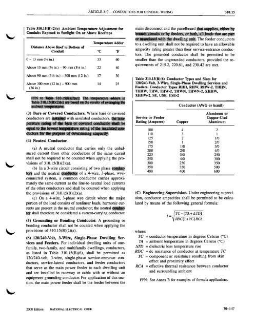
Table 310.15(B)(2)(c) Ambient Temperature Adjustment for<br />
Conduits Exposed to Sunlight On or Above Rooftops<br />
Temperature Adder<br />
Distance Above Roof to Bottom of<br />
Conduit °C of<br />
0- 13 mm (VZ in.) 33 60<br />
Above 13 mm (VZ in.) - 90 mm (3Yz in.) 22 40<br />
Above 90 mm (3Yz in.) - 300 mm (12 in.) 17 30<br />
Above 300 mm (12 in.) - 900 mm 14 25<br />
(36 in.)<br />
main disconnect <strong>and</strong> the panelboard<br />
The feeder conductors<br />
to a dwelling unit shall not be required to have an allowable<br />
ampacity rating greater than their service-entrance conductors.<br />
The grounded conductor shall be permitted to be<br />
smaller than the ungrounded conductors, provided the requirements<br />
of 215.2, 220.61, <strong>and</strong> 230.42 are met.<br />
Table 310.15(B)(6) Conductor Types <strong>and</strong> Sizes for<br />
120/240-Volt, 3·Wire, Single-Phase Dwelling Services <strong>and</strong><br />
Feeders. Conductor Types RHH, RHW, RHW·2, THHN,<br />
THHW, THW, THW-2, THWN, THWN-2, XHHW,<br />
XHHW·2, SE, USE, USE-2<br />
Conductor (AWG or kcmil)<br />
(3) Bare or Covered Conductors. Where bare or covered<br />
conductorsare_ with insulated conductors,<br />
(4) Neutral Conductor.<br />
(a) A neutral conductor that carries only the unbalanced<br />
current from other conductors of the same circuit<br />
shall not be required to be counted when applying the provisions<br />
of 31O.l5(B)(2)(a).<br />
(b) In a 3-wire circuit consisting of two phase •••<br />
<strong>and</strong> the neutral of a 4-wire, 3-phase, wyeconnected<br />
system, a common conductor carries approximately<br />
the same current as the line-to-neutralload currents<br />
of the other conductors <strong>and</strong> shall be counted when applying<br />
the provisions of 310.15(B)(2)(a).<br />
(c) On a 4-wire, 3-phase wye circuit where the major<br />
portion of the load consists of nonlinear loads, harmonic currents<br />
are present in the neutral conductor; the neutral•••<br />
... shall therefore be considered a current-carrying conductor.<br />
(5) Grounding or Bonding Conductor. A grounding or<br />
bonding conductor shall not be counted when applying the<br />
provisions of 310.15(B)(2)(a).<br />
(6) 120/240-Volt, 3·Wire, Single-Phase Dwelling Services<br />
<strong>and</strong> Feeders. For individual dwelling units of onefamily,<br />
two-family, <strong>and</strong> multifamily dwellings, conductors,<br />
as listed in Table 31O.15(B)(6), shall be permitted as<br />
1201240-volt, 3-wire, single-phase service-entrance conductors,<br />
service-lateral conductors, <strong>and</strong> feeder conductors<br />
that serve as the main power feeder to each dwelling unit<br />
<strong>and</strong> are installed in raceway or cable with or without an<br />
equipment grounding conductor. For application of this section,<br />
the main power feeder shall be the feeder between the<br />
Aluminum or<br />
Service or Feeder<br />
Copper-Clad<br />
Rating (Amperes) Copper Aluminum<br />
100 4 2<br />
110 3 1<br />
125 2 1/0<br />
150 1 2/0<br />
175 1/0 3/0<br />
200 2/0 4/0<br />
225 3/0 250<br />
250 4/0 300<br />
300 250 350<br />
350 350 500<br />
400 400 600<br />
(C) Engineering Supervision. Under engineering supervision,<br />
conductor ampacities shall be permitted to be calculated<br />
by means of the following general formula:<br />
1= TC-(TA+D.1D)<br />
RDC(l+YC)RCA<br />
where:<br />
TC =conductor temperature in degrees Celsius (0e)<br />
TA = ambient temperature in degrees Celsius (OC)<br />
I1TD = dielectric loss temperature rise<br />
RDC = dc resistance of conductor at temperature TC<br />
YC =component ac resistance resulting from skin<br />
effect <strong>and</strong> proximity effect<br />
RCA = effective thermal resistance between conductor<br />
<strong>and</strong> surrounding ambient<br />
FPN: See Annex B for examples of formula applications.<br />
2008 Edition NATIONAL ELECTRICAL CODE 70-147