Chapter 3 Wiring Methods and Materials
Chapter 3 Wiring Methods and Materials
Chapter 3 Wiring Methods and Materials

You also want an ePaper? Increase the reach of your titles
YUMPU automatically turns print PDFs into web optimized ePapers that Google loves.
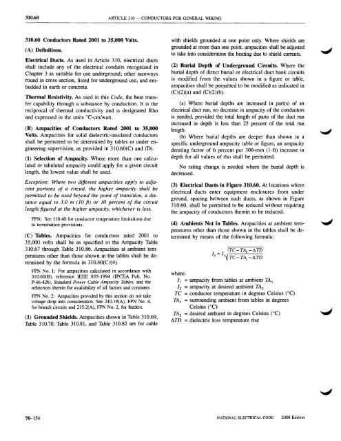
310.60 ARTICLE 310 - CONDUCTORS FOR GENERAL WIRING<br />
310.60 Conductors Rated 2001 to 35,000 Volts.<br />
(A) Definitions.<br />
Electrical Ducts. As used in Article 310, electrical ducts<br />
shall include any of the electrical conduits recognized in<br />
<strong>Chapter</strong> 3 as suitable for use underground; other raceways<br />
round in cross section, listed for underground use, <strong>and</strong> embedded<br />
in earth or concrete.<br />
Thermal Resistivity. As used in this Code, the heat transfer<br />
capability through a substance by conduction. It is the<br />
reciprocal of thermal conductivity <strong>and</strong> is designated Rho<br />
<strong>and</strong> expressed in the units DC-em/watt.<br />
(B) Ampacities of Conductors Rated 2001 to 35,000<br />
Volts. Ampacities for solid dielectric-insulated conductors<br />
shall be permitted to be determined by tables or under engineering<br />
supervision, as provided in 31O.60(C) <strong>and</strong> (D).<br />
(1) Selection of Ampacity. Where more than one calculated<br />
or tabulated ampacity could apply for a given circuit<br />
length, the lowest value shall be used.<br />
Exception: Where two different ampacities apply to adjacent<br />
portions of a circuit, the higher ampacity shall be<br />
permitted to be used beyond the point of transition, a distance<br />
equal to 3.0 m (10 ft) or 10 percent of the circuit<br />
length figured at the higher ampacity, whichever is less.<br />
FPN: See 110.40 for conductor temperature limitations due<br />
to termination provisions.<br />
(C) Tables. Ampacities for conductors rated 2001 to<br />
35,000 volts shall be as specified in the Ampacity Table<br />
310.67 through Table 310.86. Ampacities at ambient temperatures<br />
other than those shown in the tables shall be determined<br />
by the formula in 31O.60(C)(4).<br />
FPN No.1: For ampacities calculated in accordance with<br />
31O.60(B), reference IEEE 835-1994 (IPCEA Pub. No.<br />
P-46-426), St<strong>and</strong>ard Power Cable Ampacity Tables, <strong>and</strong> the<br />
references therein for availability of all factors <strong>and</strong> constants.<br />
FPN No.2: Ampacities provided by this section do not take<br />
voltage drop into consideration. See 210.19(A), FPN No.4,<br />
for branch circuits <strong>and</strong> 215.2(A), FPN No.2, for feeders.<br />
(1) Grounded Shields. Ampacities shown in Table 310.69,<br />
Table 310.70, Table 310.81, <strong>and</strong> Table 310.82 are for cable<br />
with shields grounded at one point only. Where shields are<br />
grounded at more than one point, ampacities shall be adjusted<br />
to take into consideration the heating due to shield currents.<br />
(2) Burial Depth of Underground Circuits. Where the<br />
burial depth of direct burial or electrical duct bank circuits<br />
is modified from the values shown in a figure or table,<br />
ampacities shall be permitted to be modified as indicated in<br />
(C)(2)(a) <strong>and</strong> (C)(2)(b).<br />
(a) Where burial depths are increased in partes) of an<br />
electrical duct run, no decrease in ampacity of the conductors<br />
is needed, provided the total length of parts of the duct run<br />
increased in depth is less than 25 percent of the total run<br />
length.<br />
(b) Where burial depths are deeper than shown in a<br />
specific underground ampacity table or figure, an ampacity<br />
derating factor of 6 percent per 300-rnm (l-ft) increase in<br />
depth for all values of rho shall be permitted.<br />
No rating change is needed where the burial depth is<br />
decreased.<br />
(3) Electrical Ducts in Figure 310.60. At locations where<br />
electrical ducts enter equipment enclosures from under<br />
ground, spacing between such ducts, as shown in Figure<br />
310.60, shall be permitted to be reduced without requiring<br />
the ampacity of conductors therein to be reduced.<br />
(4) Ambients Not in Tables. Ampacities at ambient temperatures<br />
other than those shown in the tables shall be determined<br />
by means of the following formula:<br />
TC-TA;. -I1TD<br />
I =1<br />
2 I TC-TA j<br />
-I1TD<br />
where:<br />
II = ampacity from tables at ambient TAl<br />
1 2 = ampacity at desired ambient TA 2<br />
TC = conductor temperature in degrees Celsius (DC)<br />
TAl = surrounding ambient from tables in degrees<br />
Celsius (DC)<br />
TA 2 = desired ambient in degrees Celsius (DC)<br />
fiTD = dielectric loss temperature rise<br />
70-154<br />
NATIONAL ELECTRICAL CODE<br />
ZOOS Edition