Chapter 3 Wiring Methods and Materials
Chapter 3 Wiring Methods and Materials
Chapter 3 Wiring Methods and Materials

Create successful ePaper yourself
Turn your PDF publications into a flip-book with our unique Google optimized e-Paper software.
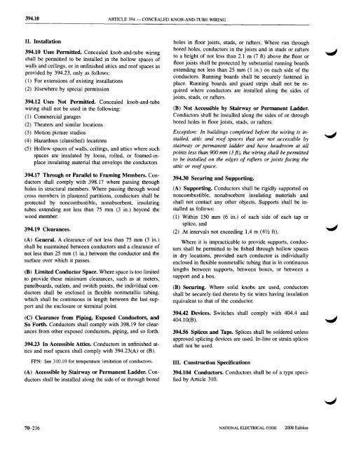
394.10 ARTICLE 394 - CONCEALED KNOB-AND-TUBE WIRING<br />
II. Installation<br />
394.10 Uses Permitted. Concealed knob-<strong>and</strong>-tube wiring<br />
shall be permitted to be installed in the hollow spaces of<br />
walls <strong>and</strong> ceilings, or in unfinished attics <strong>and</strong> roof spaces as<br />
provided by 394.23, only as follows:<br />
(1) For extensions of existing installations<br />
(2) Elsewhere by speciall permission<br />
394.12 Uses Not Permitted. Concealed knob-<strong>and</strong>-tube<br />
wiring shall not be used in the following:<br />
(1) Commercial garages<br />
(2) Theaters <strong>and</strong> similar locations<br />
(3) Motion picture studios<br />
(4) Hazardous (classified) locations<br />
(5) Hollow spaces of walls, ceilings, <strong>and</strong> attics where such<br />
spaces are insulated by loose, rolled, or foamed-inplace<br />
insulating material that envelops the conductors<br />
394.17 Through or Parallel to Framing Members. Conductors<br />
shall comply with 398.17 where passing through<br />
holes in structural members. Where passing through wood<br />
cross members in plastered partitions, conductors shall be<br />
protected by noncombustible, nonabsorbent, insulating<br />
tubes extending not less than 75 mm (3 in.) beyond the<br />
wood member.<br />
394.19 Clearances.<br />
(A) General. A clearance of not less than 75 mm (3 in.)<br />
shall be maintained between conductors <strong>and</strong> a clearance of<br />
not less than 25 mm (1 in.) between the conductor <strong>and</strong> the<br />
surface over which it passes.<br />
(B) Limited Conductor Space. Where space is too limited<br />
to provide these minimum clearances, such as at meters,<br />
panelboards, outlets, <strong>and</strong> switch points, the individual conductors<br />
shall be enclosed in flexible nonmetallic tubing,<br />
which shall be continuous in length between the last support<br />
<strong>and</strong> the enclosure or terminal point.<br />
(C) Clearance from Pil)ing, Exposed Conductors, <strong>and</strong><br />
So Forth. Conductors shall comply with 398.19 for clearances<br />
from other exposed conductors, piping, <strong>and</strong> so forth.<br />
394.23 In Accessible Attics. Conductors in unfinished attics<br />
<strong>and</strong> roof spaces shall comply with 394.23(A) or (B).<br />
FPN: See 310.10 for temperature limitation of conductors.<br />
(A) Accessible by Stairway or Permanent Ladder. Conductors<br />
shall be installed along the side of or through bored<br />
holes in floor joists, studs, or rafters. Where run through<br />
bored holes, conductors in the joists <strong>and</strong> in studs or rafters<br />
to a height of not less than 2.1 m (7 ft) above the floor or<br />
floor joists shall be protected by substantial running boards<br />
extending not less than 25 mm (1 in.) on each side of the<br />
conductors. Running boards shall be securely fastened in<br />
place. Running boards <strong>and</strong> guard strips shall not be required<br />
where conductors are installed along the sides of<br />
joists, studs, or rafters.<br />
(B) Not Accessible by Stairway or Permanent Ladder.<br />
Conductors shall be installed along the sides of or through<br />
bored holes in floor joists, studs, or rafters.<br />
Exception: In buildings completed before the wiring is installed,<br />
attic <strong>and</strong> roof spaces that are not accessible by<br />
stairway or permanent ladder <strong>and</strong> have headroom at all<br />
points less than 900 mm (3 ft), the wiring shall be permitted<br />
to be installed on the edges of rafters or joists facing the<br />
attic or roof space.<br />
394.30 Securing <strong>and</strong> Supporting.<br />
(A) Supporting. Conductors shall be rigidly supported on<br />
noncombustible, nonabsorbent insulating materials <strong>and</strong><br />
shall not contact any other objects. Supports shall be installed<br />
as follows:<br />
(1) Within 150 mm (6 in.) of each side of each tap or<br />
splice, <strong>and</strong><br />
(2) At interval s not exceeding 1.4 m (4 V2 ft).<br />
Where it is impracticable to provide supports, conductors<br />
shall be permitted to be fished through hollow spaces<br />
in dry locations, provided each conductor is individually<br />
enclosed in flexible nonmetallic tubing that is in continuous<br />
lengths between supports, between boxes, or between a<br />
support <strong>and</strong> a box.<br />
(B) Securing. Where solid knobs are used, conductors<br />
shall be securely tied thereto by tie wires having insulation<br />
equivalent to that of the conductor.<br />
394.42 Devices. Switches shall comply with 404.4 <strong>and</strong><br />
404.IO(B).<br />
394.56 Splices <strong>and</strong> Taps. Splices shall be soldered unless<br />
approved splicing devices are used. In-line or strain splices<br />
shall not be used.<br />
III. Construction Specifications<br />
394.104 Conductors. Conductors shall be of a type specified<br />
by Article 310.<br />
70-236<br />
NATIONAL ELECTRICAL CODE<br />
2008 Edition