Chapter 3 Wiring Methods and Materials
Chapter 3 Wiring Methods and Materials
Chapter 3 Wiring Methods and Materials

You also want an ePaper? Increase the reach of your titles
YUMPU automatically turns print PDFs into web optimized ePapers that Google loves.
ARTICLE 392 -<br />
CABLE TRAYS<br />
392.8<br />
(H) Exposed <strong>and</strong> Accessible. Cable trays shall be exposed<br />
<strong>and</strong> accessible except as permitted by 392.6(G).<br />
(I) Adequate Access. Sufficient space shall be provided<br />
<strong>and</strong> maintained about cable trays to permit adequate access<br />
for installing <strong>and</strong> maintaining the cables.<br />
(J) Raceways, Cables, Boxes, <strong>and</strong> Conduit Bodies Supported<br />
from Cable Tray Systems. In industrial facilities<br />
where conditions of maintenance <strong>and</strong> supervision ensure<br />
that only qualified persons service the installation <strong>and</strong><br />
where the cable tray systems are designed <strong>and</strong> installed to<br />
support the load, such systems shall be permitted to support<br />
raceways <strong>and</strong> cables, <strong>and</strong> boxes <strong>and</strong> conduit bodies covered<br />
in 314.1. For raceways terminating at the tray, a listed cable<br />
tray clamp or adapter shall be used to securely fasten the<br />
raceway to the cable tray system. Additional supporting <strong>and</strong><br />
securing of the raceway shall be in accordance with the<br />
requirements of the appropriate raceway article.<br />
For raceways or cables running parallel to <strong>and</strong> attached<br />
to the bottom or side of a cable tray system, fastening <strong>and</strong><br />
supporting shall be in accordance with the requirements of<br />
the appropriate raceway or cable article.<br />
For boxes <strong>and</strong> conduit bodies attached to the bottom or<br />
side of a cable tray system, fastening <strong>and</strong> supporting shall<br />
be in accordance with the requirements of 314.23.<br />
392.7 Grounding.<br />
(A) Metallic Cable Trays. Metallic cable trays that support<br />
electrical conductors shall be grounded as required for<br />
conductor enclosures in accordance with 250.96 <strong>and</strong> ~<br />
(B) Steel or Aluminum Cable Tray Systems. Steel or<br />
aluminum cable tray systems shall be permitted to be used<br />
as equipment grounding conductors, provided all the following<br />
requirements are met:<br />
(1) The cable tray sections <strong>and</strong> fittings ~ identified ~':g<br />
~~~nt grounding W.',~{jf.<br />
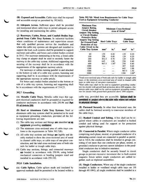
(2) The minimum cross-sectional area of cable trays conform<br />
to the requirements in Table 392.7(B).<br />
(3) All cable tray sections <strong>and</strong> fittings ~ legibly <strong>and</strong> durably<br />
marked to show the cross-sectional area of metal<br />
in channel cable trays, or cable trays of one-piece construction,<br />
<strong>and</strong> Ithe total cross-sectional area of both side<br />
rails for ladder or trough cable trays.<br />
(4) Cable tray sections, fittings, <strong>and</strong> connected raceways<br />
~ bonded in accordance with 250.96, using bolted<br />
mechanical connectors or bonding jumpers sized <strong>and</strong><br />
installed in accordance with 250.102.<br />
392.8 Cable Insuallation.<br />
(A) Cable Splices. Cable splices made <strong>and</strong> insulated by<br />
approved methods shall be permitted to be located within a<br />
Table 392.7(B) Metal Area Requirements for Cable Trays<br />
Used as Equipment Grounding Conductor<br />
Maximum Fuse<br />
Ampere Rating, Minimum Cl'Oss-Sectional<br />
Circuit Breaker<br />
Ampere Trip Setting,<br />
Area of Metal B<br />
_<br />
or Circuit Breaker<br />
Protective Relay<br />
Ampere Trip Setting<br />
Aluminum<br />
for Ground-Fault Steel Cable Trays Cable Trays<br />
Protection of Any<br />
Cable Circuit in the<br />
Cable Tray System mm 2 in. 2 mm 2 in. 2<br />
60 129 0.20 129 0.20<br />
100 258 0.40 129 0.20<br />
200 451.5 0.70 129 0.20<br />
400 645 1.00 258 0.40<br />
600 967.5 l.50 b 258 0.40<br />
1000 387 0.60<br />
1200 645 1.00<br />
1600 967.5 1.50<br />
2000 1290 2.oo b<br />
"Total cross-sectional area of both side rails for ladder or trough cable<br />
trays; or the minimum cross-sectional area of metal in channel cable<br />
trays or cable trays of one-piece construction.<br />
bSteel cable trays shall not be used as equipment grounding conduc<br />
tors for circuits with ground-fault protection above 600 amperes. Alu<br />
minum cable trays shall not be used as equipmtmt grounding conduc<br />
tors for circuits with ground-fault protection above 2000 amperes.<br />
cable tray, provided they are accessible.<br />
(B) Fastened Securely. In other than horizontal runs, the<br />
cables shall be fastened securely to transverse members of<br />
the cable trays.<br />
(C) Bushed Conduit <strong>and</strong> Thbing. A box shall not be required<br />
where cables or conductors are installed in bushed<br />
conduit <strong>and</strong> tubing used for support or for protection<br />
against physical damage.<br />
(D) Connected in Parallel. Where singIe conductor cables<br />
comprising each phase, neutral, or grounded conductor of n<br />
alternating-current circuit are connected in parallel as permitted<br />
in 310.4, the conductors shall be installed in groups consisting<br />
of not more than one conductor pt:r phase, neutral, or<br />
grounded conductor to prevent current imbalance in the paralleled<br />
conductors due to inductive reactance.<br />
Single conductors shall be securely bound in circuit<br />
groups to prevent excessive movement due to fault-current<br />
magnetic forces unless single conductors are cabled together,<br />
such as triplexed assemblies.<br />
(E) Single Conductors. Where any of the single conductors<br />
installed in ladder or ventilated trough cable trays are 1/0<br />
through 4/0 AWG, all single conductors shall be installed in a<br />
2008 Edition NATIONAL ELECTRICAL CODE<br />
76-231