Chapter 3 Wiring Methods and Materials
Chapter 3 Wiring Methods and Materials
Chapter 3 Wiring Methods and Materials

Create successful ePaper yourself
Turn your PDF publications into a flip-book with our unique Google optimized e-Paper software.
ARTICLE 372 -<br />
CELLULAR CONCRETE FLOOR RACEWAYS<br />
372.2<br />
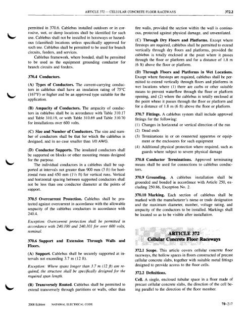
permitted in 370.6. Cablebus installed outdoors or in corrosive,<br />
wet, or damp locations shall be identified for such<br />
use. Cablebus shall not be installed in hoistways or hazardous<br />
(classified) locations unless specifically approved for<br />
such use. Cablebus shall be permitted to be used for branch<br />
circuits, feeders, <strong>and</strong> services.<br />
Cablebus framework, where bonded, shall be permitted<br />
to be used as the equipment grounding conductor for<br />
branch circuits <strong>and</strong> feeders.<br />
370.4 Conductors..<br />
(A) Types of Conductors. The current-carrying conductors<br />
in cablebus shall have an insulation rating of 75°C<br />
(167°F) or higher <strong>and</strong> be an approved type suitable for the<br />
application.<br />
(B) Ampacity of Conductors. The ampacity of conductors<br />
in cablebus shall be in accordance with Table 310.17<br />
<strong>and</strong> Table 310.19, or with Table 310.69 <strong>and</strong> Table 310.70<br />
for installations ov,~r 600 volts.<br />
(C) Size <strong>and</strong> Number of Conductors. The size <strong>and</strong> number<br />
of conductors shall be that for which the cablebus is<br />
designed, <strong>and</strong> in no case smaller than 1/0 AWG.<br />
(D) Conductor Supports. The insulated conductors shall<br />
be supported on blocks or other mounting means designed<br />
for the purpose.<br />
The individual conductors in a cablebus shall be supported<br />
at intervals not greater than 900 mm (3 ft) for horizontal<br />
runs <strong>and</strong> 450 mm (I 1/2 ft) for vertical runs. Vertical<br />
<strong>and</strong> horizontal spacing between supported conductors shall<br />
not be less than one conductor diameter at the points of<br />
support.<br />
370.5 Overcurrent Protection. Cab1ebus shall be protected<br />
against overcurrent in accordance with the allowable<br />
ampacity of the cablebus conductors in accordance with<br />
240.4.<br />
Exception: Overcurrent protection shall be permitted in<br />
accordance with 240.100 <strong>and</strong> 240.101 for over 600 volts,<br />
nominal.<br />
370.6 Support <strong>and</strong> Extension Through Walls <strong>and</strong><br />
Floors.<br />
(A) Support. Cablebus shall be securely supported at intervals<br />
not exceeding 3.7 m (12 ft).<br />
Exception: Where spans longer than 3.7 m (12 fl) are required,<br />
the structure shall be specifically designed for the<br />
required span length.<br />
(B) Transversely Routed. Cablebus shall be permitted to<br />
extend transversely through partitions or walls, other than<br />
fire walls, provided the section within the wall is continuous,<br />
protected against physical damage, <strong>and</strong> unventilated.<br />
(C) Through Dry Floors <strong>and</strong> Platforms. Except where<br />
firestops are required, cab1ebus shall be permitted to extend<br />
vertically through dry floors <strong>and</strong> platforms, provided the<br />
cablebus is totally enclosed at the point where it passes<br />
through the floor or platform <strong>and</strong> for a distance of 1.8 m<br />
(6 ft) above the floor or platform.<br />
(D) Through Floors <strong>and</strong> Platforms in Wet Locations.<br />
Except where firestops are required, cablebus shall be permitted<br />
to extend vertically through floors <strong>and</strong> platforms in<br />
wet locations where (I) there are curbs or other suitable<br />
means to prevent waterflow through the floor or platform<br />
opening, <strong>and</strong> (2) where the cablebus is totally enclosed at<br />
the point where it passes through the floor or platform <strong>and</strong><br />
for a distance of 1.8 m (6 ft) above the floor or platform.<br />
370.7 Fittings. A cablebus system shall include approved<br />
fittings for the following:<br />
(1) Changes in horizontal or vertical direction of the run<br />
(2) Dead ends<br />
(3) Terminations in or on connected apparatus or equipment<br />
or the enclosures for such equipment<br />
(4) Additional physical protection where required, such as<br />
guards where subject to severe physical damage<br />
370.8 Conductor Terminations. Approved terminating<br />
means shall be used for connections to cablebus conductors.<br />
370.9 Grounding. A cablebus installation shall be<br />
grounded <strong>and</strong> bonded in accordance with Article 250, excluding<br />
250.86, Exception No.2.<br />
370.10 Marking. Each section of cablebus shall be<br />
marked with the manufacturer's name or trade designation<br />
<strong>and</strong> the maximum diameter, number, voltage rating, <strong>and</strong><br />
ampacity of the conductors to be installed. Markings shall<br />
be located so as to be visible after installation.<br />
372.1 Scope. This article covers cellular concrete floor<br />
raceways, the hollow spaces in floors constructed of precast<br />
cellular concrete slabs, together with suitable metal fittings<br />
designed to provide access to the floor cells.<br />
372.2 Definitions.<br />
Cell. A single, enclosed tubular space in a floor made of<br />
precast cellular concrete slabs, the direction of the cell being<br />
parallel to the direction of the floor member.<br />
2008 Edition NAT10NAL ELECTRICAL CODE<br />
70--217