Chapter 3 Wiring Methods and Materials
Chapter 3 Wiring Methods and Materials
Chapter 3 Wiring Methods and Materials

You also want an ePaper? Increase the reach of your titles
YUMPU automatically turns print PDFs into web optimized ePapers that Google loves.
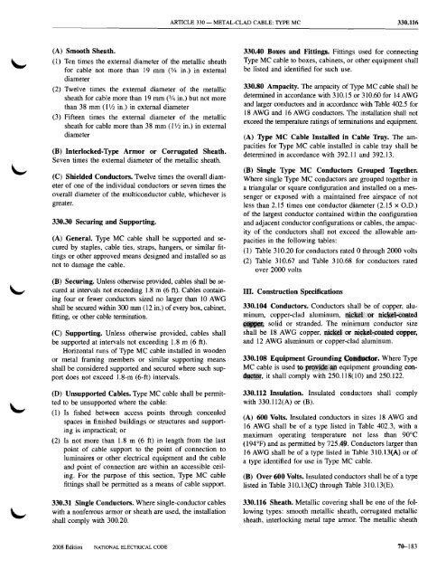
ARTICLE 330 -<br />
METAL-CLAD CABLE: TIPE MC<br />
330.116<br />
(A) Smooth Sheath.<br />
(1) Ten times the external diameter of the metallic sheath<br />
for cable not more than 19 mm (314 in.) in external<br />
diameter<br />
(2) Twelve times the external diameter of the metallic<br />
sheath for cable more than 19 mm (314 in.) but not more<br />
than 38 mm (11/2 in.) in external diameter<br />
(3) Fifteen times the external diameter of the metallic<br />
sheath for cable more than 38 mm (1'/2 in.) in external<br />
diameter<br />
(B) Interlocked-Type Armor or Corrugated Sheath.<br />
Seven times the external diameter of the metallic sheath.<br />
(C) Shielded Conductors. Twelve times the overall diameter<br />
of one of the individual conductors or seven times the<br />
overall diameter of the multiconductor cable, whichever is<br />
greater.<br />
330.30 Securing <strong>and</strong> Supporting.<br />
(A) General. Type MC cable shall be supported <strong>and</strong> secured<br />
by staples, cable ties, straps, hangers, or similar fittings<br />
or other approved means designed <strong>and</strong> installed so as<br />
not to damage the cable.<br />
(B) Securing. Unless otherwise provided, cables shall be secured<br />
at intervals not exceeding 1.8 m (6 ft). Cables containing<br />
four or fewer conductors sized no larger than 10 AWG<br />
shall be secured within 300 mm (12 in.) of every box, cabinet,<br />
fitting, or other cable termination.<br />
(C) Supporting. Unless otherwise provided, cables shall<br />
be supported at intervals not exceeding 1.8 m (6 ft).<br />
Horizontal runs of Type MC cable installed in wooden<br />
or metal framing members or similar supporting means<br />
shall be considered supported <strong>and</strong> secured where such support<br />
does not exceed 1.8-m (6-ft) intervals.<br />
(D) Unsupported Cables. Type MC cable shall be permitted<br />
to be unsupported where the cable:<br />
(1) Is fished between access points through concealed<br />
spaces in finished buildings or structures <strong>and</strong> supporting<br />
is impractical; or<br />
(2) Is not more than 1.8 m (6 ft) in length from the last<br />
point of cable support to the point of connection to<br />
luminaires or other electrical equipment <strong>and</strong> the cable<br />
<strong>and</strong> point of connection are within an accessible ceiling.<br />
For the purpose of this section, Type MC cable<br />
fittings shall be permitted as a means of cable support.<br />
330.31 Single Conductors. Where single-conductor cables<br />
with a nonferrous armor or sheath are used, the installation<br />
shall comply with 300.20.<br />
330.40 Boxes <strong>and</strong> Fittings. Fittings used for connecting<br />
Type MC cable to boxes, cabinets, or other equipment shall<br />
be listed <strong>and</strong> identified for such use.<br />
330.80 Ampacity. The ampacity of Type MC cable shall be<br />
determined in accordance with 310.15 or 310.60 for 14 AWG<br />
<strong>and</strong> larger conductors <strong>and</strong> in accordance with Table 402.5 for<br />
18 AWG <strong>and</strong> 16 AWG conductors. The installation shall not<br />
exceed the temperature ratings of terminations <strong>and</strong> equipment.<br />
(A) Type MC Cable Installed in Cable Tray. The ampacities<br />
for Type MC cable installed in cable tray shall be<br />
determined in accordance with 392.11 <strong>and</strong> 392.13.<br />
(B) Single Type MC Conductors Grouped Together.<br />
Where single Type MC conductors are grouped together in<br />
a triangular or square configuration <strong>and</strong> installed on a messenger<br />
or exposed with a maintained free airspace of not<br />
less than 2.15 times one conductor diameter (2.15 x a.D.)<br />
of the largest conductor contained within the configuration<br />
<strong>and</strong> adjacent conductor configurations or cables, the ampacity<br />
of the conductors shall not exceed the allowable ampacities<br />
in the following tables:<br />
(1) Table 310.20 for conductors rated 0 through 2000 volts<br />
(2) Table 310.67 <strong>and</strong> Table 310.68 for conductors rated<br />
over 2000 volts<br />
III. Construction Specifications<br />
330.104 Conductors. Conductors shall be of copper, aluminum,<br />
copper-clad aluminum, ~~f1~i!!iot.·n~.~Q3ted<br />
••• solid or str<strong>and</strong>ed. The minimum conductor size<br />
shall be 18 AWG copper, ~~lll;ot