Chapter 3 Wiring Methods and Materials
Chapter 3 Wiring Methods and Materials
Chapter 3 Wiring Methods and Materials

You also want an ePaper? Increase the reach of your titles
YUMPU automatically turns print PDFs into web optimized ePapers that Google loves.
300.19 ARTICLE 300 - WIRING METHODS<br />
be installed complete between outlet, junction, or splicing<br />
points prior to the installation of conductors. Where required<br />
to facilitate the installation of utilization equipment,<br />
the raceway shall be permitted to be initially installed without<br />
a terminating connection at the equipment. Prewired<br />
raceway assemblies shall be permitted only where specifically<br />
permitted in this Code for the applicable wiring<br />
method.<br />
Exception: Short sections of raceways used to contain conductors<br />
or cable assemblies for protection from physical<br />
damage shall not be required to be installed complete between<br />
outlet, junction, or splicing points.<br />
(B) Welding. Metal raceways shall not be supported, terminated,<br />
or connected by welding to the raceway unless<br />
specifically designed to be or otherwise specifically permitted<br />
to be in this Code.<br />
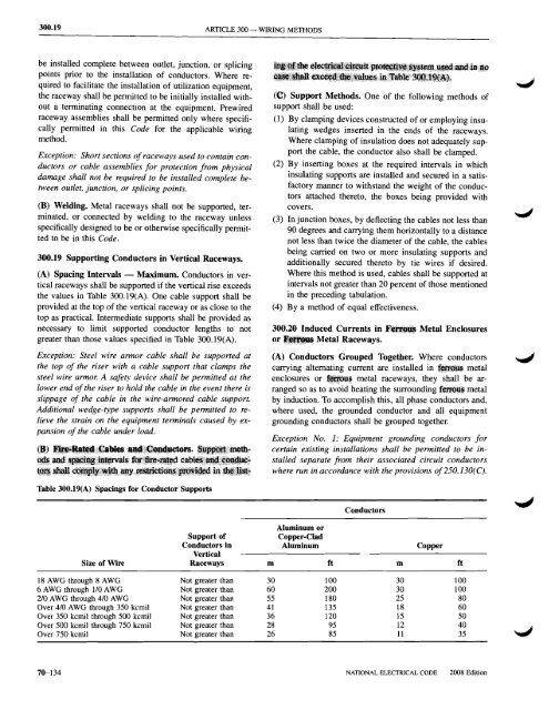
300.19 Supporting Conductors in Vertical Raceways.<br />
(A) Spacing Intervals - Maximum. Conductors in vertical<br />
raceways shall be supported if the vertical rise exceeds<br />
the values in Table 300.19(A). One cable support shall be<br />
provided at the top of the vertical raceway or as close to the<br />
top as practical. Intermediate supports shall be provided as<br />
necessary to limit supported conductor lengths to not<br />
greater than those values specified in Table 300.19(A).<br />
Exception: Steel wire armor cable shall be supported at<br />
the top of the riser with a cable support that clamps the<br />
steel wire armor. A safety device shall be permitted at the<br />
lower end of the riser to hold the cable in the event there is<br />
slippage of the cable in the wire-armored cable support.<br />
Additional wedge-type supports shall be permitted to relieve<br />
the strain on the equipment terminals caused by expansion<br />
of the cable under load.<br />
((;]i) Support <strong>Methods</strong>. One of the following methods of<br />
support shall be used:<br />
(1) By clamping devices constructed of or employing insulating<br />
wedges inserted in the ends of the raceways.<br />
Where clamping of insulation does not adequately support<br />
the cable, the conductor also shall be clamped.<br />
(2) By inserting boxes at the required intervals in which<br />
insulating supports are installed <strong>and</strong> secured in a satisfactory<br />
manner to withst<strong>and</strong> the weight of the conductors<br />
attached thereto, the boxes being provided with<br />
covers.<br />
(3) In junction boxes, by deflecting the cables not less than<br />
90 degrees <strong>and</strong> carrying them horizontally to a distance<br />
not less than twice the diameter of the cable, the cables<br />
being carried on two or more insulating supports <strong>and</strong><br />
additionally secured thereto by tie wires if desired.<br />
Where this method is used, cables shall be supported at<br />
intervals not greater than 20 percent of those mentioned<br />
in the preceding tabulation.<br />
(4) Bya method of equal effectiveness.<br />
300.20 Induced Currents in F~~ Metal Enclosures<br />
or II!~ Metal Raceways.<br />
(A) Conductors Grouped Together. Where conductors<br />
carrying alternating current are installed in metal<br />
enclosures or 1iP",~ metal raceways, they shall be arranged<br />
so as to avoid heating the surrounding feJ'tOij~ metal<br />
by induction. To accomplish this, all phase conductors <strong>and</strong>,<br />
where used, the grounded conductor <strong>and</strong> all equipment<br />
grounding conductors shall be grouped together.<br />
Exception No.1: Equipment grounding conductors for<br />
certain existing installations shall be permitted to be installed<br />
separate from their associated circuit conductors<br />
where run in accordance with the provisions of250.130(C).<br />
Table 300.19(A) Spacings for Conductor Supports<br />
Conductors<br />
Aluminum or<br />
Support of<br />
Copper-Clad<br />
Conductors in Aluminum Copper<br />
Vertical<br />
Size of Wire Raceways m ft m ft<br />
18 AWG through 8 AWG<br />
6 AWG through 1/0 AWG<br />
2/0 AWG through 4/0 AWG<br />
Over 4/0 AWG through 350 kemil<br />
Over 350 kemil through 500 kemil<br />
Over 500 kemil through 750 kemil<br />
Over 750 kemil<br />
Not greater than 30<br />
Not greater than 60<br />
Not greater than 55<br />
Not greater than 41<br />
Not greater than 36<br />
Not greater than 28<br />
Not greater than 26<br />
100<br />
200<br />
180<br />
135<br />
120<br />
95<br />
85<br />
30 100<br />
30 100<br />
25 80<br />
18 60<br />
15 50<br />
12 40<br />
11 35<br />
70-134<br />
NATIONAL ELECTRICAL CODE<br />
2008 Edition