Chapter 3 Wiring Methods and Materials
Chapter 3 Wiring Methods and Materials
Chapter 3 Wiring Methods and Materials

Create successful ePaper yourself
Turn your PDF publications into a flip-book with our unique Google optimized e-Paper software.
355.22 ARTICLE 355 - REINFORCED THERMOSETIING RESIN CONDUIT: lYPE RTRC<br />
FPN: The trade sizes <strong>and</strong> metric designators are for identification<br />
purposes only <strong>and</strong> do not relate to actual dimensions.<br />
See 300.1 (C).<br />
355.22 Number of Conductors. The number of conductors<br />
shall not exceed that permitted by the percentage fill<br />
specified in Table 1, <strong>Chapter</strong> 9. Cables shall be permitted to<br />
be installed where such use is not prohibited by the respective<br />
cable articles. The number of cables shall not exceed<br />
the allowable percentage fill specified in Table 1, <strong>Chapter</strong> 9.<br />
355.24 Bends - How Made. Bends shall be so made that<br />
the conduit will not be damaged <strong>and</strong> the internal diameter<br />
of the conduit will not be effectively reduced. Field bends<br />
shall be made only with bending equipment identified for the<br />
purpose. The radius of the curve to the centerline of such<br />
bends shall not be less than shown in Table 2, <strong>Chapter</strong> 9.<br />
355.26 Bends - Number in One Run. There shall not be<br />
more than the equivalent of four quarter bends (360 degrees<br />
total) between pull points, for example, conduit bodies <strong>and</strong><br />
boxes.<br />
355.28 Trimming. All cut ends shall be trimmed inside<br />
<strong>and</strong> outside to remove rough edges.<br />
355.30 Securing <strong>and</strong> Supporting. RTRC shall be installed<br />
as a complete system in accordance with 300.18 <strong>and</strong> shall<br />
be securely fastened in place <strong>and</strong> supported in accordance<br />
with 355.30(A) <strong>and</strong> (B) or permitted to be unsupported in<br />
accordance with 355.30(C).<br />
(A) Securely Fastened. RTRC shall be securely fastened<br />
within 900 mm (3 ft) of each outlet box, junction box,<br />
device box, conduit body, or other conduit termination.<br />
Conduit listed for securing at other than 900 mm (3 ft) shall<br />
be permitted to be installed in accordance with the listing.<br />
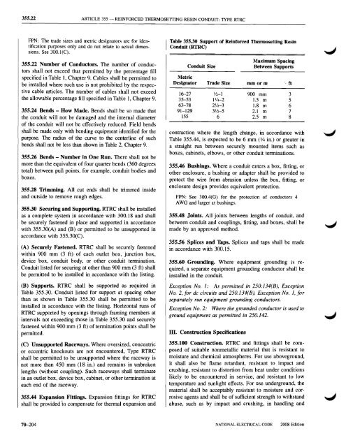
(B) Supports. RTRC shall be supported as required in<br />
Table 355.30. Conduit listed for support at spacing other<br />
than as shown in Table 355.30 shall be permitted to be<br />
installed in accordance with the listing. Horizontal runs of<br />
RTRC supported by openings through framing members at<br />
intervals not exceeding those in Table 355.30 <strong>and</strong> securely<br />
fastened within 900 mm (3 ft) of termination points shall be<br />
permitted.<br />
(C) Unsupported Raceways. Where oversized, concentric<br />
or eccentric knockouts are not encountered, Type RTRC<br />
shall be permitted to be unsupported where the raceway is<br />
not more than 450 mm (18 in.) <strong>and</strong> remains in unbroken<br />
lengths (without coupling). Such raceways shall terminate<br />
in an outlet box, device box, cabinet, or other termination at<br />
each end of the raceway.<br />
355.44 Expansion Fittings. Expansion fittings for RTRC<br />
shall be provided to compensate for thermal expansion <strong>and</strong><br />
Table 355.30 Support of Reinforced Thermosetting Resin<br />
Conduit (RTRC)<br />
Conduit Size<br />
Maximum Spacing<br />
Between Supports<br />
Metric<br />
Designator Trade Size mmorm " ft<br />
16-27 \/2-1 900 mm 3<br />
35-53 11/4-2 1.5 m 5<br />
63-78 21/2-3 1.8 m 6<br />
91-129 3 1 /2-5 2.1 m 7<br />
155 6 2.5 m 8<br />
contraction where the length change, in accordance with<br />
Table 355.44, is expected to be 6 mm (V4 in.) or greater in<br />
a straight run between securely mounted items such as<br />
boxes, cabinets, elbows, or other conduit terminations.<br />
355.46 Bushings. Where a conduit enters a box, fitting, or<br />
other enclosure, a bushing or adapter shall be provided to<br />
protect the wire from abrasion unless the box, fitting, or<br />
enclosure design provides equivalent protection.<br />
FPN: See 300.4(G) for the protection of conductors 4<br />
AWG <strong>and</strong> larger at bushings.<br />
355.48 Joints. All joints between lengths of conduit, <strong>and</strong><br />
between conduit <strong>and</strong> couplings, fitting, <strong>and</strong> boxes, shall be<br />
made by an approved method.<br />
355.56 Splices <strong>and</strong> Taps. Splices <strong>and</strong> taps shall be made<br />
in accordance with 300.15.<br />
355.60 Grounding. Where equipment grounding is required,<br />
a separate equipment grounding conductor shall be<br />
installed in the conduit.<br />
Exception No. 1: As permitted in 250.134(B), Exception<br />
No. 2,jor dc circuits <strong>and</strong> 250. 134(B), Exception No. 1,for<br />
separately run equipment grounding conductors.<br />
Exception No.2: Where the grounded conductor is used to<br />
ground equipment as permitted in 250.142.<br />
III. Construction Specifications<br />
355.100 Construction. RTRC <strong>and</strong> fittings shall be composed<br />
of suitable nonmetallic material that is resistant to<br />
moisture <strong>and</strong> chemical atmospheres. For use aboveground,<br />
it shall also be flame retardant, resistant to impact <strong>and</strong><br />
crushing, resistant to distortion from heat under conditions<br />
likely to be encountered in service, <strong>and</strong> resistant to low<br />
temperature <strong>and</strong> sunlight effects. For use underground, the<br />
material shall be acceptably resistant to moisture <strong>and</strong> corrosive<br />
agents <strong>and</strong> shall be of sufficient strength to withst<strong>and</strong><br />
abuse, such as by impact <strong>and</strong> crushing, in h<strong>and</strong>ling <strong>and</strong><br />
76-204<br />
NATIONAL ELECTRICAL CODE<br />
2008 Edition