Chapter 3 Wiring Methods and Materials
Chapter 3 Wiring Methods and Materials
Chapter 3 Wiring Methods and Materials

You also want an ePaper? Increase the reach of your titles
YUMPU automatically turns print PDFs into web optimized ePapers that Google loves.
324.60 ARTICLE 326 - INTEGRATED GAS SPACER CABLE: lYPE lOS<br />
conductors, <strong>and</strong> for electrically connecting the assembly to the<br />
metal cable shields <strong>and</strong> to equipment grounding conductors.<br />
324.60 Grounding. All metal shields, boxes, receptacle<br />
housings, <strong>and</strong> self-contained devices shall be electrically<br />
continuous to the equipment grounding conductor of the<br />
supplying branch circuit. All such electrical connections<br />
shall be made with connectors identified for this use. The<br />
electrical resistivity of such shield system shall not be more<br />
than that of one conductor of the 'Jype FCC cable used in<br />
the installation.<br />
DI. Construction<br />
324.100 Construction.<br />
(A) Type FCC Cable. Type FCC cable shall be listed for<br />
use with the FCC system <strong>and</strong> shall consist of three, four, or<br />
five flat copper conductors, one of which shall be an equipment<br />
grounding conductor.<br />
(B) Shields.<br />
(1) <strong>Materials</strong> <strong>and</strong> Dimensions. All top <strong>and</strong> bottom shields<br />
shall be of designs <strong>and</strong> materials identified for their use.<br />
Top shields shall be metal. Both metallic <strong>and</strong> nonmetallic<br />
materials shall be permitted for bottom shields.<br />
(2) Resistivity. Metal shields shall have cross-sectional areas<br />
that provide for electrical resistivity of not more than<br />
that of one conductor of the Type FCC cable used in the<br />
installation.<br />
324.101 Corrosion Resistance. Metal components of the<br />
system shall be either corrosion resistant, coated with<br />
corrosion-resistant materials, or insulated from contact with<br />
corrosive substances.<br />
324.112 Insulation. The insulating material of the cable<br />
shall be moisture resistant <strong>and</strong> flame retardant. All insulating<br />
materials in the FCC systems shall be identified for<br />
their use.<br />
324.120 Markings.<br />
(A) Cable Marking. Type FCC cable shall be clearly <strong>and</strong><br />
durably marked on both sides at intervals of not more than<br />
610 mm (24 in.) with the information required by<br />
310.11 (A) <strong>and</strong> with the following additional information:<br />
(1) Material of conductors<br />
(2) Maximum temperature rating<br />
(3) Ampacity<br />
(B) Conductor Identification. Conductors shall be clearly<br />
<strong>and</strong> durably identified on both sides throughout their length<br />
as specified in 310.12.<br />
I. General<br />
326.1 Scope. This article covers the use, installation, <strong>and</strong><br />
construction specifications for integrated gas spacer cable,<br />
Type IGS.<br />
326.2 Definition.<br />
Integrated Gas Spacer Cable, Type IGS. A factory assembly<br />
of one or more conductors, each individually insulated <strong>and</strong><br />
enclosed in a loose fit, nonmetallic flexible conduit as an integrated<br />
gas spacer cable rated 0 through 600 volts.<br />
II. Installation<br />
326.10 Uses Permitted. Type IGS cable shall be permitted<br />
for use under ground, including direct burial in the earth, as<br />
the following:<br />
(1) Service-entrance conductors<br />
(2) Feeder or branch-circuit conductors<br />
326.12 Uses Not Permitted. Type IGS cable shall not be<br />
used as interior wiring or be exposed in contact with buildings.<br />
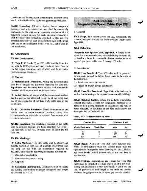
326.24 Bending Radius. Where the coilable nonmetallic<br />
conduit <strong>and</strong> cable is bent for installation purposes or is<br />
flexed or bent during shipment or installation, the radii of<br />
bends measured to the inside of the bend shall not be less<br />
than specified in Table 326.24.<br />
Table 326.24 Minimum Radii of Bends<br />
Conduit Size<br />
Minimum Radii<br />
Metric Designator Trade Size mm in.<br />
53 2 600 24<br />
78 3 900 35<br />
103 4 1150 45<br />
326.26 Bends. A run of Type IGS cable between pull<br />
boxes or terminations shall not contain more than the<br />
equivalent of four quarter bends (360 degrees total), including<br />
those bends located immediately at the pull box or<br />
terminations.<br />
326.40 Fittings. Terminations <strong>and</strong> splices for Type IGS<br />
cable shall be identified as a type that is suitable for maintaining<br />
the gas pressure within the conduit. A valve <strong>and</strong> cap<br />
shall be provided for each length of the cable <strong>and</strong> conduit<br />
to check the gas pressure or to inject gas into the conduit.<br />
70--180<br />
NATIONAL ELECTRICAL CODE<br />
2008 Edition