Chapter 3 Wiring Methods and Materials
Chapter 3 Wiring Methods and Materials
Chapter 3 Wiring Methods and Materials

You also want an ePaper? Increase the reach of your titles
YUMPU automatically turns print PDFs into web optimized ePapers that Google loves.
ARTICLE 394 -<br />
CONCEALED KNOB-AND-TUBE WIRING<br />
394.2<br />
Exception to (B)(3):' For solid bottom cable trays the ampacify<br />
of single conductor cables shall be determined by<br />
310. 15(C).<br />
(4) Where single conductors are installed in a triangular or<br />
square configuration in uncovered cable trays, with a<br />
maintained free airspace of not less than 2.15 times one<br />
conductor diameter (2.15 x 0.0.) of the largest conductor<br />
contained within the configuration <strong>and</strong> adjacent<br />
conductor configurations or cables, the ampacity of I/O<br />
AWG <strong>and</strong> larger cables shall not exceed the allowable<br />
ampacities of two or three single insulated conductors<br />
rated 0 through 2000 volts supported on a messenger in<br />
accordance with 31O.15(B).<br />
FPN: See Table 3110.20.<br />
multiyonduetQr caples ~l31~,.!n(13)<br />
jr~siongle·~oi!l9u~*"<br />
cabws.ptovided ,tb~t the' following COl!lditi0ns apply'!<br />
(1) The SUQl of tbe, multicon9uclor cable filllJ~; ...,;a.~<br />
centage 'Of the allowable fiUllfe/Ji for ,thettll)\~"'~<br />
per 392.9, <strong>and</strong> the single-condttet()rcaQ-w.~lk~as~<br />
percentage of the allowable fill area for tbe, ~f~·<br />
lated per 392.10, totals not ll1(J1l'e than 1(ll;) 'Pe"itf+<br />
(2) fyJulticonductor cables ~ 'in$~ed accl~PJ,1t()i.~~9,~~~<br />
~lt2,:1~<strong>and</strong>' 392.8(q)::~~(.E).<br />
392.12 Number of Type MV <strong>and</strong> Type MC Cables (2001<br />
Volts or Over) in Cable Trays. The number of cables rated<br />
2001 volts or over permitted in a single cable tray shall not<br />
exceed the requirements of this section.<br />
The sum of the diameters of single-conductor <strong>and</strong> multiconductor<br />
cables shall not exceed the cable tray width,<br />
<strong>and</strong> the cables shall be installed in a single layer. Where<br />
single conductor cables are triplexed, quadruplexed, or<br />
bound together in circuit groups, the sum of the diameters<br />
of the single conductors shall not exceed the cable tray<br />
width, <strong>and</strong> these groups shall be installed in single layer<br />
arrangement.<br />
392.13 Ampacity of Type MV <strong>and</strong> Type MC Cables<br />
(2001 Volts or Over) in Cable Trays. The ampacity of<br />
cables, rated 2001 volts, nominal, or over, installed according<br />
to 392.12 shall not exceed the requirements of this<br />
section.<br />
(A) Multiconductor Cables (2001 Volts or Over). The<br />
allowable ampacity of multiconductor cables shall be as<br />
given in Table 310.75 <strong>and</strong> Table 310.76, subject to the<br />
following provisions:<br />
(1) Where cable trays are continuously covered for more<br />
than 1.8 ill (6 ft) with solid unventilated covers, not<br />
more than 95 percent of the allowable ampacities of<br />
Table 310.75 <strong>and</strong> Table 310.76 shall be permitted for<br />
multiconductor cables.<br />
(2) Where multiconductor cables are installed in a single<br />
layer in uncovered cable trays, with maintained spacing<br />
of not less than one cable diameter be:tween cables, the<br />
ampacity shall not exceed the allowable ampacities of<br />
Table 310.71 <strong>and</strong> Table 310.72.<br />
(B) Single-Conductor Cables (2001 Volts or Over). The<br />
ampacity of single-conductor cables, or single conductors<br />
cabled together (triplexed, quadruplexed, etc.), shall comply<br />
with the following:<br />
(1) The ampacities for I/O AWG <strong>and</strong> larger singleconductor<br />
cables in uncovered cable trays shall not exceed<br />
75 percent of the allowable ampacities in Table<br />
310.69 <strong>and</strong> Table 310.70. Where the cable trays are<br />
covered for more than 1.8 m (6 ft) with solid unventilated<br />
covers, the ampacities for 1/0 AWG <strong>and</strong> larger singleconductor<br />
cables shall not exceed 70 percent of the allowable<br />
ampacities in Table 310.69 <strong>and</strong> Table 310.70.<br />
(2) Where single-conductor cables are installed in a single<br />
layer in uncovered cable trays, with a maintained space<br />
of not less than one cable diameter between individual<br />
conductors, the ampacity of I/O AWG <strong>and</strong> larger cables<br />
shall not exceed the allowable ampacities in Table<br />
310.69 <strong>and</strong> Table 310.70.<br />
(3) Where single conductors are installed in a triangular or<br />
square configuration in uncovered cable trays, with a<br />
maintained free air space of not less than 2.15 times the<br />
diameter (2.15 x 0.0.) of the largest conductor contained<br />
within the configuration <strong>and</strong> adjacent conductor<br />
configurations or cables, the ampacity of I/O AWG <strong>and</strong><br />
larger cables shall not exceed the allowable ampacities<br />
in Table 310.67 <strong>and</strong> Table 310.68.<br />
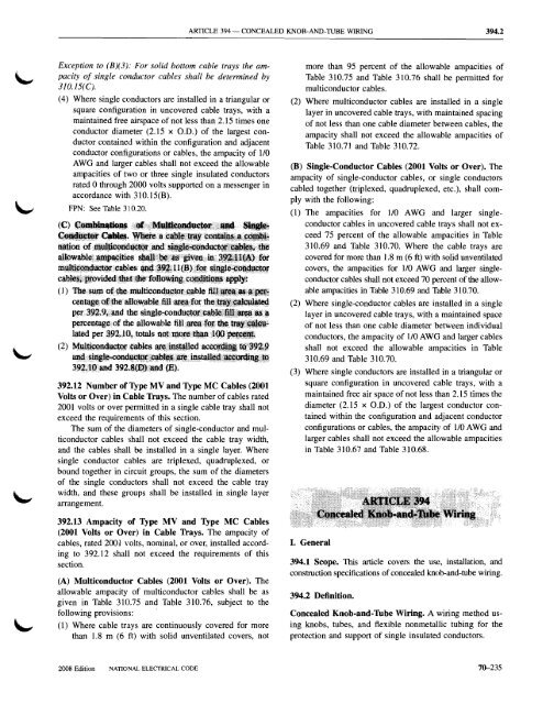
I. General<br />
394.1 Scope. This article covers the use, installation, <strong>and</strong><br />
construction specifications of concealed knob-<strong>and</strong>-tube wiring.<br />
394.2 Definition.<br />
Concealed Knob-<strong>and</strong>-lUbe <strong>Wiring</strong>. A wiring method using<br />
knobs, tubes, <strong>and</strong> flexible nonmetallic tubing for the<br />
protection <strong>and</strong> support of single insulated conductors.<br />
2008 Edition NATIONAL ELECfRICAL CODE<br />
76-235