The Performance, Safety and Production Benefits of SPS Structures ...
The Performance, Safety and Production Benefits of SPS Structures ...
The Performance, Safety and Production Benefits of SPS Structures ...

You also want an ePaper? Increase the reach of your titles
YUMPU automatically turns print PDFs into web optimized ePapers that Google loves.
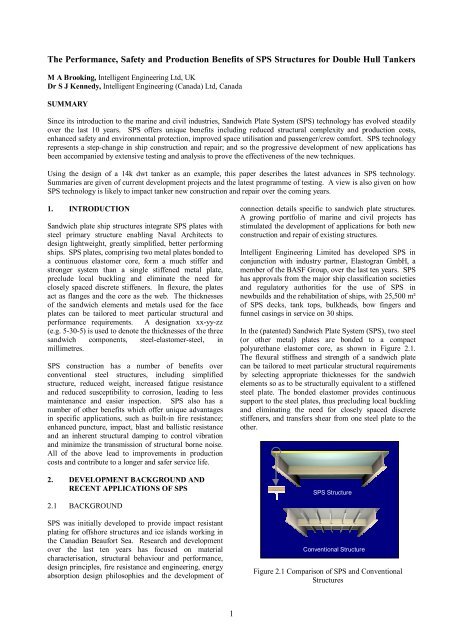
<strong>The</strong> elastomer, as a two-part liquid, is injected intoclosed cavities formed by steel plates <strong>and</strong> perimeter bars(not shown in Figure 2.1) that are welded or glued toboth plates. To obtain a bond strength greater than <strong>of</strong> 6MPa once cured, the plates are grit blasted <strong>and</strong> need to beclean, free <strong>of</strong> contaminants <strong>and</strong> dry when the elastomer isinjected.A summary <strong>of</strong> the technology development undertaken todate <strong>and</strong> future development work is given in AppendixA.<strong>The</strong>re is increasing interest in new constructionapplications. Ship operators are keen to take advantage<strong>of</strong> the benefits in improved lifetime performance,reduced maintenance <strong>and</strong> structural simplicity. An <strong>SPS</strong>design <strong>of</strong> a Rhine river barge is currently undergoingclass approval; <strong>and</strong> a prototype service barge for BritishWaterways has been completed <strong>and</strong> is undergoing trialsas part <strong>of</strong> a major fleet replacement project. <strong>SPS</strong> is alsogaining wider use in specific components on ships, wheresome <strong>of</strong> the unique properties such as fire protection <strong>and</strong>noise attenuation are exploited.2.2 RECENT APPLICATIONS OF <strong>SPS</strong><strong>SPS</strong> has found many applications in both civil <strong>and</strong>marine industries. Recent projects include a replacementhighways bridge in Canada, where <strong>SPS</strong> was used toreplace a concrete deck, thus allowing the capacity <strong>of</strong> thebridge to be increased without upgrading the foundations<strong>and</strong> substructure.Figure 2.4 Newbuild RoRo Ferry Funnel CasingsFigure 2.2 Indented Bulk Carrier Tank TopIn the marine industry much <strong>of</strong> the experience to date hasbeen in deck re-instatements <strong>of</strong> vehicle ferries, <strong>of</strong>fshoresupport vessels <strong>and</strong> bulk carriers. Figure 2.2 shows thetank top <strong>of</strong> a bulk carrier that has suffered extremeindentation <strong>of</strong> the plating due impact from heavy cargoes<strong>and</strong> grab damage. <strong>The</strong> tank top plating was repairedusing an <strong>SPS</strong> Overlay which returned the structure to a“better than new” condition, as shown in figure 2.3.After 6 months’ service the repaired plating has sufferedvirtually no significant indentation under the sameoperating conditions. <strong>The</strong> tank top remains flat <strong>and</strong> even,allowing faster unloading <strong>and</strong> more efficient cleaning <strong>of</strong>the hold, thus speeding up the turn-round time <strong>and</strong>improving the readiness for the next cargo.Figure 2.3 <strong>SPS</strong> Overlay Repair on Bulk Carrier TankTopIn 2003 Flensburger Schiffbau Gesellschaft commencedthe fitting <strong>of</strong> <strong>SPS</strong> panels in the funnel casings <strong>of</strong> a series<strong>of</strong> new ro-ro vessels (Figure 2.4). <strong>The</strong> <strong>SPS</strong> panels wereselected over conventional steel because significantspace savings were required to house machinery <strong>and</strong>equipment in a confined space. <strong>The</strong>y are approved toA60 st<strong>and</strong>ard, with no additional insulation; <strong>and</strong> this inassociation with the elimination <strong>of</strong> secondary stiffenersmet the requirements for the application. <strong>The</strong> panels arestiff, easy to erect <strong>and</strong> significantly flatter than equivalentstiffened steel panels.A potential application for <strong>SPS</strong> is the “double hulling” <strong>of</strong>existing single hull vessels. A scheme has beendeveloped which uses pre-fabricated <strong>SPS</strong> panels to formthe inner hull plating. Use <strong>of</strong> <strong>SPS</strong> in this applicationhelps maximise cargo carrying capacity by keeping theinternal structure <strong>of</strong> the inner hull to a minimum. Tominimise the impact <strong>of</strong> time-out-<strong>of</strong>-service, IE’s solutioninvolves dropping the large panel sections through slotsmade in the existing deck or outer hull as shown inFigure 2.5.Other newbuild development projects include:• UR S21 compliant hatch covers: IE has developedhatch cover designs for panamax <strong>and</strong> capesize bulkcarriers. <strong>SPS</strong> provides an ideal solution to the newrequirements, as it has a high resistance to theincreased pressures <strong>and</strong> impact loads anticipated bythe new regulations. <strong>The</strong> simplified structure gives2
hatch covers that are structurally efficient <strong>and</strong> easyto manufacture.• Lightweight vehicle decks for dedicated vehiclecarriers: IE is working with industry partners todevelop <strong>SPS</strong> deck structures that are efficient bothstructurally <strong>and</strong> in use <strong>of</strong> space.Figure 3.1 Typical Section Through aDouble Hulled VLCCFigure 2.5 Use <strong>of</strong> <strong>SPS</strong> Panels to “Double-Hull” existingSingle Hull Tankers• Kawasaki Ship Building Corporation <strong>and</strong> IE aredeveloping <strong>SPS</strong> scantlings for the revolutionary SeaArrow bow. This innovative application <strong>of</strong> <strong>SPS</strong>will provide a structure that will resist high impactloads from the sea, but will collapse in a controlledmanner in a collision. This will minimise overalldamage to both vessels <strong>and</strong> reduce the risk <strong>of</strong>flooding <strong>and</strong> loss <strong>of</strong> cargo.• IE has commissioned a study by StrathclydeUniversity, which investigates the economics <strong>of</strong>using <strong>SPS</strong> in the production <strong>of</strong> superstructures. <strong>The</strong>initial results show that labour costs for constructionusing pre-fabricated <strong>SPS</strong> panels can be reduced byover 50% against a conventional all-steel alternative.3. THE APPLICATION OF <strong>SPS</strong> TO DOUBLEHULL TANKERS3.1 BACKGROUND TO DOUBLE HULLTANKERS<strong>The</strong> tank configuration <strong>of</strong> double hull tankers is nowfamiliar to the marine industry. Figure 3.1 shows atypical cross section through a double hull VLCC. <strong>The</strong>resulting structure is based entirely on conventional shipconstruction concepts, with transverse web frames thatsupport stiffened plate panels for the inner <strong>and</strong> outerhulls. In the example shown there are approximately 300longitudinal stiffeners, each <strong>of</strong> which has to pass throughevery transverse web frame <strong>and</strong> bulkhead leading to15,000 or more intersections over the cargo region alone.<strong>The</strong> transition from single to double hulled vessels hasbeen driven by the imperatives <strong>of</strong> safety <strong>and</strong>environmental protection. <strong>The</strong> paradox is that theresulting ships are more complex than before, with asubstantial increase in the number <strong>of</strong> fatigue <strong>and</strong>corrosion prone details, where risk <strong>of</strong> initiating structuralfailure can occur. As well as the basic requirement fortankers to have double hulls, there are now additionalregulatory measures stipulating increased survey <strong>and</strong>maintenance (including access for inspection) on tankers.It has been argued that similar st<strong>and</strong>ards <strong>of</strong> inspection<strong>and</strong> maintenance <strong>of</strong> single hulled ships would haveresulted in a similar improvement to safety, but at alower cost.In light <strong>of</strong> recent incidents involving tankers, especiallyolder single hull ships, it is clear that improvements intanker safety are important <strong>and</strong> urgently required.However, the fact remains that tankers are now morecostly to build <strong>and</strong> maintain than ever before.3.2 DESIGN ISSUES FOR CONVENTIONALSTEEL DESIGNSFrom the point <strong>of</strong> view <strong>of</strong> hull design, the ideal ship:• Has a structure which is sympathetic in terms <strong>of</strong>construction – simple <strong>and</strong> easy to build• Requires little through-life maintenance• Suffers little or no corrosion• Has a minimum <strong>of</strong> breakdown in coatings• Suffers no cracking or other structural problems• Does not unduly vibrateSince the 1960s considerable experience has beenaccumulated in service performance <strong>of</strong> tanker designswhich have grown in size, <strong>of</strong>ten through a process <strong>of</strong>extrapolation <strong>of</strong> structural arrangements.Through the 1970s, ‘80s <strong>and</strong> ‘90s, advances incomputing technology have enabled naval architects togain a better underst<strong>and</strong>ing <strong>of</strong> dynamic loads from waves<strong>and</strong> ship motions, along with the importance <strong>of</strong> detaildesign, structural alignment <strong>and</strong> construction quality.Design processes have improved <strong>and</strong> lessons from3
construction related failures <strong>and</strong> insufficient maintenancecontinue to be addressed.In the early days <strong>of</strong> double hull tankers there was littleknowledge on which to draw, other than the experience<strong>of</strong> single hulled tankers. Whilst this was extensive, theindustry was unsure how it would extrapolate to doublehulled vessels.<strong>and</strong> 3.4. Such failures had been experienced on singlehull tankers <strong>and</strong> much work in the marine industry hasbeen undertaken to underst<strong>and</strong> <strong>and</strong> avoid such problems.3.2(a)Early Concerns <strong>of</strong> Double Hulled TankersFollowing the introduction <strong>of</strong> OPA90, it became clearthat double hulled tankers would supersede single hulldesigns. Concerns were raised about the universaladoption <strong>of</strong> a st<strong>and</strong>ard requiring tankers to be <strong>of</strong> doublehull construction, many <strong>of</strong> which centred around theconsequences <strong>of</strong> an accident involving a double hullvessel, compared to that <strong>of</strong> a single hull.Figure 3.2 Critical Areas for Fatigue <strong>and</strong> StructuralFailures on Double Hulled TankersAMSA has recently published a brief summarycomparison <strong>of</strong> single <strong>and</strong> double hull tankers (Ref 1),which gives a very clear description <strong>of</strong> the merits <strong>and</strong>disadvantages <strong>of</strong> double hulled vessels. <strong>The</strong>se includeoil outflow <strong>and</strong> considerations <strong>of</strong> hydrostatic balancefollowing collisions <strong>and</strong> grounding. <strong>The</strong> difficulties <strong>of</strong>salvaging a double hulled vessel due to flooding <strong>and</strong> lostbuoyancy following a grounding incident are alsoaddressed. <strong>The</strong> intact <strong>and</strong> damaged stability <strong>of</strong> doublehulled tankers was also questioned, due to concerns overthe raised centre <strong>of</strong> gravity associated with doublebottom tanks <strong>and</strong> the greater free surfaces <strong>of</strong> wide tanks.Other concerns centred around structural issues <strong>and</strong> werelegitimately raised in light <strong>of</strong> the experience borne outover the previous 20 to 30 years. Double hulled tankershave a high level <strong>of</strong> structural complexity, the number <strong>of</strong>structural intersections is almost twice that <strong>of</strong> anequivalent size single hull ship. Leakages <strong>of</strong> cargo intothe ballast spaces from cracks in the inner hull structurewere seen as a major risk. Fatigue <strong>and</strong> corrosion werehighlighted as potential causes <strong>of</strong> such failures.Fatigue:<strong>The</strong> well documented service histories <strong>of</strong> single hulltankers were used to highlight potential areas for fatigueproblems. Figure 3.2 shows the areas that are critical forfatigue on double hulled tankers. <strong>The</strong>se includeconnections <strong>of</strong> inner hull plating at the upper <strong>and</strong> lowerintersections <strong>of</strong> the sloping hopper, connections at thetoes <strong>of</strong> brackets <strong>and</strong> stringers <strong>and</strong> the intersections <strong>of</strong>secondary longitudinal stiffeners with transversemembers.Secondary stiffeners <strong>and</strong> their associated intersectiondetails are well known sources <strong>of</strong> structural problems.Depending on their location, geometric configuration <strong>and</strong>construction, a combination <strong>of</strong> service loads, residualstresses <strong>and</strong> corrosion can result in coating breakdown<strong>and</strong> fatigue cracks. This can lead to ongoing propagation<strong>and</strong> eventual structural failure as shown in Figures 3.3Figure 3.3 Typical Fatigue Crack Found on Side ShellLongitudinal Stiffeners <strong>of</strong> Single Hull TankersUse <strong>of</strong> higher tensile steel has also contributed to fatiguefailures. Apart from fatigue lives being reduced by ageneral increase in working stresses associated withreduced scantlings, problems have also been encounteredwith increased residual stresses introduced duringconstruction. <strong>The</strong>se arise in areas such as stiffenerintersections, where a welding sequence has createdresidual stresses that are difficult to “relieve” in HT steel.When using this material, care is required with detaildesign <strong>and</strong> with construction processes.Figure 3.4 Early Experiences <strong>of</strong> Fatigue Damage Led toCrack Propagation <strong>and</strong> Larger Structural Failure4
Corrosion:Undetected corrosion has been a major cause <strong>of</strong> some <strong>of</strong>the most noteworthy marine disasters. A paper producedby OCIMF (Ref 2) provides a very concise summary <strong>of</strong>the potential problems facing the operators <strong>of</strong> doublehulled tankers. In particular it highlights the difficulties<strong>of</strong> coating, inspecting <strong>and</strong> maintaining the ballast spaces,which in conventional steel designs are cellular, with acomplex arrangement <strong>of</strong> internal stiffeners, brackets <strong>and</strong>associated structural details. In today’s double hulledtankers it is common practice to provide full coating <strong>of</strong>the ballast tanks, but to coat only the bottoms <strong>of</strong> cargotanks. A second paper by OCIMF (Ref 3) provides avery clear view <strong>of</strong> the various sources <strong>of</strong> corrosionaffecting tankers <strong>and</strong> their influence on corrosion rates.<strong>The</strong>se include coatings, washing processes, sulphurcontent <strong>of</strong> cargo, inert gas quality, construction materials<strong>and</strong> others.It is clear that control <strong>of</strong> corrosion plays a major part inthe safe operation <strong>and</strong> maintenance <strong>of</strong> a double hulledtanker. Conventional steel designs, with their inherentcomplexity are costly to protect <strong>and</strong> maintain. This isdue to the large surface areas, difficulty <strong>of</strong> access <strong>and</strong>large numbers <strong>of</strong> points for potential initiation <strong>of</strong> coatingbreakdown.Experience <strong>of</strong> double hulled tankers to date:To date there is little documented operational experienceon the structural performance <strong>of</strong> double hulled tankers.Anecdotal evidence suggests that the experience has s<strong>of</strong>ar been satisfactory. Whilst there are cases <strong>of</strong> minorstructural failures, such as fatigue cracks in stiffenerintersections <strong>and</strong> inner hull connections with the slopinghopper, these have been found <strong>and</strong> addressed with nomajor incidents. Regular inspection <strong>and</strong> maintenanceremains a clear necessity.A paper by Bergesen, produced in 2000 (Ref 4) providesa comprehensive summary <strong>of</strong> experience in operatingthree double hulled VLCCs. <strong>The</strong> paper concludes with anumber <strong>of</strong> measures for protecting both ballast <strong>and</strong> cargotanks from corrosion. <strong>The</strong> paper also notes that waveloads on the bow have resulted in local buckling <strong>of</strong>internal structure <strong>and</strong> hull plating deformation, resultingin a “starved horse” appearance.Today’s double hulled tankers are not known to besuffering from structural failures. However, the effortrequired to design <strong>and</strong> construct intersections with goodservice performance adds considerably to the productioncost <strong>and</strong> the problems have not been completelyeliminated.3.3 USE OF <strong>SPS</strong> IN DOUBLE HULLED TANKERSIntelligent Engineering believes that <strong>SPS</strong> technology willprovide improved safety through greater resistance toimpact, collisions, fire <strong>and</strong> explosion. Furthermore, thestructural simplification that <strong>SPS</strong> provides will givecommercial benefits in terms <strong>of</strong> reduced costs forproduction, inspection <strong>and</strong> lifetime maintenance. Byremoving secondary stiffeners from the structure, thehigh risk areas <strong>of</strong> coating breakdown, acceleratedcorrosion <strong>and</strong> fatigue cracking are eliminated.3.3(a)Design principles in using <strong>SPS</strong>Using <strong>SPS</strong> in ship structures requires a fresh view ondesign, especially in areas <strong>of</strong> structural intersections.Basic longitudinal strength is assessed in a similar way tocurrent established methods, using classic navalarchitecture theory <strong>and</strong> st<strong>and</strong>ard hull section propertycalculations. With <strong>SPS</strong> structures, the continuous inner<strong>and</strong> outer face plates <strong>of</strong> the composite s<strong>and</strong>wich areincluded in the section properties, but the elastomer coreis not included in the calculation. Depending on localstrength requirements, a portion <strong>of</strong> the steel area, aboutthe neutral axis, may be redistributed to the deck <strong>and</strong>outer hull to maintain the section modulus whilereducing overall weight.<strong>SPS</strong> design for local strength involves a new approach.Conventional ship structures are commonly designedusing established ‘empirical’ classification society rules.<strong>The</strong>se do not yet exist for <strong>SPS</strong> structures, which behaveas true composite materials with isotropic properties.Design assessment rules for s<strong>and</strong>wich plate shipstructures are being developed by Lloyd’s Register <strong>and</strong>are expected in draft form in 2005.<strong>The</strong> scantlings <strong>of</strong> <strong>SPS</strong> plating are generally in the range<strong>of</strong> 3 mm to 8 mm for the steel face plates <strong>and</strong> 20 mm to50 mm for the core thickness. <strong>The</strong> required scantlingsare a function <strong>of</strong> the loads <strong>and</strong> spacing <strong>of</strong> the supportingframing, <strong>and</strong> are currently determined by direct designcalculations, using normal stress criteria for yield <strong>and</strong>shear. Corrosion margins are added to the face plates, asrequired.<strong>SPS</strong> panels are very stable, since the stiff elastomer coreprevents local buckling effects. Semi-empiricalequations have been developed to determine the in-planeload carrying capacity for any combination <strong>of</strong> transverseloads. <strong>The</strong>se have been verified using full scale tests <strong>and</strong>non-linear finite element analyses. Current designpractice uses finite element analysis to check the in-planeload carrying capacity <strong>of</strong> <strong>SPS</strong> panels. This is achievedwith models using solid or layered shell elements toaccount for both material <strong>and</strong> geometric non-linearity.<strong>The</strong> maximum transverse framing should be in the rangebetween 3.2 to 4.0 m. <strong>SPS</strong> plating should have an aspectratio (the ratio <strong>of</strong> length <strong>of</strong> the long to short pl<strong>and</strong>imension) between 1.4 <strong>and</strong> 1.7, to produce an economicplate with the maximum buckling strength. <strong>SPS</strong> panelsshould be arranged so that the largest dimension isaligned along the length <strong>of</strong> the ship.5
<strong>SPS</strong> structures have a high inherent resistance to fatigue.<strong>The</strong> bond between the elastomer core <strong>and</strong> the face platesis virtually fatigue insensitive. Joints between <strong>SPS</strong>panels <strong>and</strong> connections <strong>of</strong> <strong>SPS</strong> panels to supportingstructure have a good inherent resistance <strong>and</strong> may bechecked using st<strong>and</strong>ard fatigue assessment techniquesalready used in the marine industry.3.3(b) Summary <strong>of</strong> <strong>SPS</strong> applications in double hulltankers<strong>SPS</strong> can replace traditional stiffened plating in the maindeck, inner <strong>and</strong> outer hull <strong>and</strong> longitudinal bulkheads ondouble hull tankers, to provide both construction <strong>and</strong>operational benefits. Without secondary stiffening, themajority <strong>of</strong> fatigue <strong>and</strong> corrosion prone details areadvantageously eliminated; <strong>and</strong> with suitably optimisedproduction techniques there are many advantages forconstruction in terms <strong>of</strong> cost <strong>and</strong> time.At the beginning <strong>of</strong> this section a list <strong>of</strong> needs for theideal ship design were suggested. In answer to thesepoints, <strong>SPS</strong> has unique properties that <strong>of</strong>fer distinctadvantages over conventional designs:• <strong>The</strong> structural simplification afforded by <strong>SPS</strong>provides the opportunity to eliminate secondarystiffeners <strong>and</strong> their associated connections withprimary structures such as transverse web frames <strong>and</strong>bulkheads.• In comparison to its all-steel counterpart, thefabrication <strong>of</strong> an <strong>SPS</strong> structure has substantially lesslabour input, reduced weld lengths <strong>and</strong> volumes,reduced surface areas for coating <strong>and</strong> reduced hullweight.• <strong>The</strong> s<strong>and</strong>wich plate dissipates highly localisedbending strains in the plating to the primary structuralframing, thus eliminating hard spots associated withcoating breakdown at stiffener intersections.• <strong>The</strong> elimination <strong>of</strong> stiffeners <strong>and</strong> connectionsremoves a source <strong>of</strong> high risk for structural failures.<strong>The</strong> impact resistance <strong>of</strong> <strong>SPS</strong> also provides improvedperformance against extreme event loading such aswave impact, slamming, grounding <strong>and</strong> collisions.• <strong>The</strong> reduced surface area <strong>of</strong> internal structures <strong>and</strong>clutter-free layout enable faster <strong>and</strong> better coatingapplication. Since paint coatings will be easier toapply <strong>and</strong> the amount <strong>of</strong> free edges <strong>and</strong> cornersgreatly reduced, the reliability <strong>of</strong> coatings will begreatly enhanced with <strong>SPS</strong> structures. This is a highcost aspect <strong>of</strong> ship maintenance, <strong>and</strong> with a currentcost <strong>of</strong> up to $35 per square meter for blasting,cleaning <strong>and</strong> paint application, there are significantlife-time savings to be made.• Inspection <strong>and</strong> maintenance are greatly reduced in<strong>SPS</strong> structures. Tank inspection will be faster <strong>and</strong>more reliable. With less cluttered structural layouts,tank drainage <strong>and</strong> cleaning will be faster <strong>and</strong> moreeffective <strong>and</strong> will help avoid the build up <strong>of</strong> silt <strong>and</strong>mud in ballast tanks.• Permanent deformation <strong>of</strong> conventional stiffenedpanels is common <strong>and</strong> <strong>of</strong>ten requires steelreplacements <strong>and</strong> strengthening during a ship’s life.<strong>The</strong> ability <strong>of</strong> <strong>SPS</strong> to absorb damage from waveimpact, grounding <strong>and</strong> collisions whilst resistingperforation <strong>of</strong> the hull, will in many cases avoidflooding <strong>and</strong> enable faster <strong>and</strong> safer recovery <strong>of</strong> agrounded ship.• <strong>SPS</strong> also allows different metals to be used on eitherside <strong>of</strong> the s<strong>and</strong>wich. This <strong>of</strong>fers new solutions tochemical tanker designers, by allowing a costeffective means <strong>of</strong> constructing tanks with stainlesssteel internal surfaces.In addition to hull structures, <strong>SPS</strong> will find many otherapplications in ships. Inherent properties, such as fireresistance <strong>and</strong> the attenuation <strong>of</strong> noise <strong>and</strong> vibration,mean that <strong>SPS</strong> will have useful applications in key areassuch as accommodation <strong>and</strong> machinery spaces. <strong>SPS</strong> mayalso provide solutions for double-hulling <strong>of</strong> existingsingle skin ships where the elimination <strong>of</strong> secondarystiffeners will minimise the impact on access to the innerhull, <strong>and</strong> hence maximise cargo carrying capacity.4. DESIGN STUDY OF SMALL PRODUCTSTANKER4.1 BACKGROUNDAs part <strong>of</strong> Intelligent Engineering’s ongoingdevelopment programme, a design study was undertakenfor the cargo tank section <strong>of</strong> a 14k dwt double-hulledproducts tanker.A conventional steel design for the ship was used as areference point for the <strong>SPS</strong> design study <strong>and</strong> the resultsare presented here in summary form. <strong>The</strong> objective <strong>of</strong>the work was to investigate the feasibility <strong>of</strong> using <strong>SPS</strong>construction on a double hull tanker <strong>and</strong> to makecomparisons between the two designs, with a view toassessing <strong>and</strong> quantifying the benefits <strong>of</strong> <strong>SPS</strong>construction. Lloyd’s Register’s Rules <strong>and</strong> ShipRightDirect Calculation Procedures were used as a basis forscantling design.<strong>SPS</strong> can replace the traditional stiffened plate <strong>of</strong> the maindeck, inner <strong>and</strong> outer side shell, double bottom <strong>and</strong>centreline longitudinal bulkhead <strong>of</strong> the tanker to provideboth construction <strong>and</strong> operational benefits. Withoutsecondary stiffening, the majority <strong>of</strong> fatigue <strong>and</strong>corrosion prone details are advantageously eliminated.<strong>The</strong> s<strong>and</strong>wich plate dissipates highly localised bendingstrains in the plating into the primary structural framing,thus eliminating the ‘hard spots’ associated with coatingbreakdown at stiffener intersections.In comparison to its all-steel counterpart, the fabrication<strong>of</strong> an <strong>SPS</strong> structure has substantially less labour input,reduced weld lengths <strong>and</strong> volumes, reduced surface areasfor coating in combination with improved coating6
application, <strong>and</strong> reduced hull weight. In operation thesmooth surfaces <strong>of</strong> <strong>SPS</strong> plating allow for better ballasttank drainage <strong>and</strong> cleaning <strong>The</strong> principle dimensions <strong>of</strong>the tanker are listed in Table 4.1.between the main web frames. Figure 4.2 shows askeletal view <strong>of</strong> the conventional steel mid-section; theinner bottom, inner skin <strong>and</strong> longitudinal bulkhead areremoved to provide a clear view <strong>of</strong> the structure.Table 4.1 Principal DimensionsLength overall: 144.0 mLength between perpendiculars: 134.5 mBreadth: 21.50 mDepth: 11.30 mDraft: 7.65 mDeadweight: 14000 tonnesCargo capacity (98%): 16660 m 3Ballast capacity: 6610 m 34.2 DESCRIPTION OF CONVENTIONAL AND<strong>SPS</strong> DESIGNDuring the design study both the conventional steel <strong>and</strong><strong>SPS</strong> designs underwent several iterations to optimise thescantlings, following the results <strong>of</strong> the FE analysescarried out using the ShipRight design assessmentprocedures. <strong>The</strong> following information is based on thefinal set <strong>of</strong> scantlings determined.Figure 4.2 Steel Tanker Structural LayoutDuring the design study it was determined that the <strong>SPS</strong>design could use a 3.5m spacing <strong>of</strong> the web frames. Allsecondary longitudinal stiffeners were eliminated fromthe structure. Double bottom girders have beenintroduced, along with an additional intermediate stringeron the side structure <strong>and</strong> centreline bulkhead. <strong>The</strong>increased floor spacing along with the additional girdersFigure 4.3 <strong>SPS</strong> Tanker Structural LayoutFigure 4.1 Sketch <strong>of</strong> Midship Section(14k dwt Products Tanker)<strong>The</strong> conventional steel design uses a st<strong>and</strong>ardconfiguration with a centreline bulkhead <strong>and</strong> “J” tankscovering the side structure <strong>and</strong> double bottom. <strong>The</strong> tanktop has a small rise <strong>of</strong> floor to aid tank drainage <strong>and</strong>stripping. Figure 4.1 shows the layout <strong>of</strong> the midshipsection, including basic dimensions. <strong>The</strong> transverseframe spacing is 3m <strong>and</strong> the longitudinal stiffenerspacing is 675mm. <strong>The</strong>re are no intermediatelongitudinal girders between the centreline bulkhead <strong>and</strong>the girders beneath the hopper side knuckle on the innerbottom. In the bilge area, additional webs are provided<strong>and</strong> stringers help maintain optimum panel sizes for the<strong>SPS</strong> plating on the external <strong>and</strong> internal hull plating.Finally, as the secondary stiffeners have been eliminated<strong>and</strong> access through the inner bottom is much improved,the height <strong>of</strong> the double bottom can be reduced by600mm, which has the additional advantage <strong>of</strong> increasingthe cargo capacity by around 6%. Figure 4.3 shows asimilar skeletal view <strong>of</strong> the <strong>SPS</strong> hull section.Table 4.2 Comparison <strong>of</strong> ScantlingsConventionalStructural Component SteelScantlingsInner Plate14 mmBottom &HopperLongitudinals HP 320x12Outer Plate14 mmBottom Keel Plate 16 mm<strong>SPS</strong> Scantlings<strong>SPS</strong> 7-50-7.5<strong>SPS</strong> 7-50-77
InnerShellOuterShellCentrelineBulkheadSideSideLongitudinalsLower StrakeMiddle StrakeUpper StrakeLower StrakeMiddle StrakeUpper StrakeStiffenersLower StrakeUpper StrakeHP 280x1214 mm13 mm12 mm15 mm14 mm13 mmHP 220x1015 mm13 mm<strong>SPS</strong> 6-40-6(5700mm a/b)<strong>SPS</strong> 5-35-5<strong>SPS</strong> 6-30-6(5700mm a/b)Main Deck Plate11 mm<strong>SPS</strong> 6-25-6Longitudinals HP 220x10Transverse Web Frame Spacing 3000mm 3500mmTable 4.3 Summary <strong>of</strong> Hull Girder Section PropertiesHull Girder Section Modulus, m 3Location Conventional SteelScantlings<strong>SPS</strong> ScantlingsKeel 7.720 6.376Tank Top 12.734 10.352Main Deck 5.255 4.534Table 4.2 lists the basic scantlings <strong>of</strong> both designs <strong>and</strong>provides a comparison <strong>of</strong> the two different structures <strong>and</strong>Table 4.3 gives a summary <strong>of</strong> hull girder sectionproperties.4.3 DESIGN ASSESSMENT SUMMARYFE analysis <strong>of</strong> the mid-section was carried out usingLR’s ShipRight direct calculation procedures, using FEmodels as shown in Figure 4.4. An example set <strong>of</strong> thetank design pressures used in the FE analysis is given inTable 4.4.StructuralComponentTable 4.4 Example Tank Design PressuresPressure(kPa)Tank Top 95OuterBottomInner SideShellOuter SideShell949394Main Deck 24LongitudinalBulkhead95CommentPressure at centreline assuming tank at98% capacity <strong>and</strong> relatively heavy cargo(specific gravity = 1.0)Pressure equal to draft (T) plus 0.5 timespassing wave height (h w)LR Direct Calculation Guidance Notes h w= 4.6x10 -2 L e -0.0044L = 3.42 mNote: Part 4, Chapter 9, Section 4, Table9.4.1 lists a design head for outer bottomh T2 = T + 0.5C w > 1.2T (T = 7.65 m,C w = 7.71x10 -2 L e -0.0044L = 5.74 m, 1.2T =9.18m)Pressure at centreline, assuming tank at98% capacity <strong>and</strong> relatively heavy cargo(specific gravity = 1.0)Pressure at baseline equal to outer bottomPressure reduces to h w at load waterline(LWL) <strong>and</strong> to zero at h w above LWL draftLR Part 3, Chapter 3, Section 5, Table3.5.1, h 2 = L/56Pressure at base <strong>of</strong> bulkhead equal to tanktop pressurePressure reduces to zero at the main deck<strong>The</strong> hull section modulus at the main deck, keel <strong>and</strong> tanktop for the steel <strong>and</strong> <strong>SPS</strong> designs are listed in Table 4.3.<strong>The</strong> <strong>SPS</strong> deck <strong>and</strong> keel section moduli are 4.8% <strong>and</strong>7.5% less than the all-steel design. In comparison to theall-steel design the balance <strong>of</strong> material (ratio <strong>of</strong> deck tokeel moduli) about the neutral axis is improved in the<strong>SPS</strong> ship. <strong>The</strong> primary bending stresses have not beenevaluated since, at the time <strong>of</strong> the design study, the stillwater bending moments for the ship were not available.<strong>The</strong> results <strong>of</strong> the FE analysis were assessed against thestress criteria listed in Table 4.5 <strong>The</strong> stress comparison<strong>of</strong> the two designs is summarised in Table 4.6Table 4.5 Double Hull Tanker - Allowable StressCriteriaStructuralMemberApplied LoadingStressComponentMaximumAllowable Stress,MPaGradeGeneralAHull girder loadsσ 175 / k L 175Hull Girder (still water & wavecombined)τ 110 / k L 110Local loads <strong>and</strong> hullgirder loadsσ 216 / k 216Local loads σ e 177 / k 177Local loadsPlating 1(in line with hull σ x 108 / k 108girder stress)Local loads(transverse to hull σ y 147 / k 147girder stress)Longitudinal Local loads σ 100 / k 100Stiffeners Local loads τ 83 / k 831. Primary structure plating including inner <strong>and</strong> outer hull <strong>and</strong>longitudinal bulkheadsNotes: • σ e = von Mises equivalent stress• σ = bending stress• τ = average shear stress over depth <strong>of</strong> web plate• For LR Grade A steel: k = 1.0, k L = 1.0Table 4.6 Analysis Stress Results – Local Pressure LoadsStructuralMemberStressQuantityAllowableStressCriteriaStress, MPaAll-SteelScantlings<strong>SPS</strong>σ x 108 88 106Tank Top Plating σ y 147 128 118σ e 177 113 110Tank Top Stiffs σ x 100 87 -Outer BottomPlatingOuter BottomStiffenersInner Side ShellPlatingOuter Side ShellPlatingσ x 108 89 102σ y 147 124 119σ e 177 115 111σ x 100 103 -σ x 108 136 * 86σ y 147 84 112σ e 177 123 102σ x 108 86 88σ y 147 59 91σ e 177 78 848
Main Deck σ x 108 - 104Plating σ y 147 - 31σ x 108 - 109Longitudinalσ y 147 - 138Bulkhead Platingσ e 177 - 131Note: * local peak stress at the location <strong>of</strong> plate thickness change,anticipated that an extension <strong>of</strong> thicker lower plate by 200 mmremoves high stress.4.4 QUANTITY COMPARISONSFollowing the design study, a comparison <strong>of</strong> the twooptimised designs was made. A 15m length <strong>of</strong> the midsectionwas used <strong>and</strong> the comparisons for weight, surfacearea <strong>and</strong> other important parameters are summarised inTables 4.7 <strong>and</strong> 4.8.StructureTable 4.7 Weight ComparisonWeight, tonnesConventionalSteelScantlings<strong>SPS</strong>ScantlingsDifferencetonnes %Double Bottom 133.4 116.8 -16.6 -12.4Side Shell 102.1 109.9 +7.8 +7.6Longitudinal24.0 22.4 -1.6 -6.6BulkheadMain Deck 50.3 52.0 +1.7 +3.4Totals 309.8 301.1 8.7 -2.8Table 4.8 Other Comparisons Between Conventional <strong>and</strong><strong>SPS</strong> DesignsStructureWeight, tonnesConventionalSteelScantlings<strong>SPS</strong>ScantlingsDifferenceDelta %Painted SurfaceArea, m 2 6280 5025 1255 -20# StiffenerIntersections310 10 310 -97Weld Volume,cm 3 215000 93000 122000 -574.5 CONCLUSIONS AND FURTHER WORK<strong>The</strong> design study verifies that <strong>SPS</strong> technology can beapplied to a double hull tanker <strong>and</strong> assessed successfullyagainst industry-st<strong>and</strong>ard assessment procedures. <strong>The</strong>study demonstrates that <strong>SPS</strong> <strong>of</strong>fers a number <strong>of</strong> benefitsto the design <strong>of</strong> double hull tankers:• <strong>The</strong> weight <strong>of</strong> the <strong>SPS</strong> design is slightly less than theconventional steel design. <strong>The</strong> weight comparisonincludes the mass <strong>of</strong> elastomer core.• <strong>The</strong> elimination <strong>of</strong> secondary stiffeners provides a20% reduction in internal surface area <strong>and</strong> representsa major saving in terms <strong>of</strong> paint volume, ease <strong>and</strong>quality <strong>of</strong> application.• <strong>The</strong> weld volume reduction <strong>of</strong> 50% is achievedthrough the elimination <strong>of</strong> stiffeners <strong>and</strong> theassociated intersections with transverse primarystructure. This represents significant savings inproduction time <strong>and</strong> cost.• <strong>The</strong> <strong>SPS</strong> design has an uncluttered internalarrangement <strong>of</strong> structure <strong>and</strong> can accommodate areduced double bottom height <strong>of</strong> up to 600mmwithout compromising access for inspection. Thisprovides a potential for an additional 6% <strong>of</strong> cargocarrying capacity.• Inspection <strong>and</strong> maintenance are greatly enhanced forthe <strong>SPS</strong> design, with easier access, faster inspection<strong>and</strong> significantly fewer locations with potential forcoating breakdown <strong>and</strong> structural failure.<strong>The</strong>re is further work to be completed. <strong>The</strong> designassessment needs to include a more complete review <strong>of</strong>longitudinal strength <strong>and</strong> verification by a classificationsociety. <strong>The</strong>re is yet more scope for optimisation <strong>of</strong> the<strong>SPS</strong> structure <strong>and</strong> further gains in structural efficiencyare expected.5. PRODUCTION METHODOLOGIES<strong>The</strong> design study summarised in Section 4 above showsthat <strong>SPS</strong> structures can be designed with weight savings<strong>and</strong> strength equivalence to conventional ship structures.<strong>Production</strong> <strong>of</strong> <strong>SPS</strong> panels involves some key processeswhich are unique to <strong>SPS</strong> technology.• <strong>The</strong> internal surfaces <strong>of</strong> the steel cavities needpreparation to achieve the required surface roughness<strong>of</strong> at least 60 microns <strong>and</strong> a surface cleanliness <strong>of</strong> SA2 ½. <strong>The</strong> preparation uses st<strong>and</strong>ard steel fabricationpractices <strong>and</strong> is best achieved using steel grit orcorundum, which have suitably hard particles <strong>and</strong> anangular pr<strong>of</strong>ile.• <strong>The</strong> internal cavities must be clean <strong>and</strong> dry prior toinjection. <strong>The</strong>y must also be airtight in order toprevent elastomer leakages during injection.• <strong>SPS</strong> panels are restrained during injection <strong>and</strong> curing.This ensures that the face plates remain flat. On aproduction line this may be achieved using simpleportable frames which can be clamped at the edges.• <strong>The</strong> injection process usually takes around 8 to 12minutes. At this stage the temperature <strong>of</strong> the panelsshould be no less than 20°C.To realise the maximum commercial benefit <strong>of</strong> <strong>SPS</strong>technology, successful integration <strong>of</strong> <strong>SPS</strong> into theproduction lines <strong>of</strong> shipyards is essential. Workcontinues with yards in Europe, Asia <strong>and</strong> N. America toimplement <strong>SPS</strong> into shipyard construction processes.Currently there are two main options for production <strong>of</strong><strong>SPS</strong> structures:• Use <strong>of</strong> pre-fabricated <strong>SPS</strong> panels delivered to theproduction line• Integration <strong>of</strong> <strong>SPS</strong> panel fabrication within theproduction lineIn the first option <strong>SPS</strong> panels are pre-fabricated to thedesigner’s specification <strong>and</strong> dimensions, away from theproduction line. This option allows for <strong>SPS</strong> panels to be9
pre-fabricated at a single site for distribution to manydifferent locations. <strong>The</strong> advantages <strong>of</strong> this method is thata specialised facility using fast, modern productiontechniques can produce panels with varying designparameters, rapidly <strong>and</strong> in great numbers. <strong>The</strong>economies <strong>of</strong> scale <strong>of</strong> such plant mean that theproduction costs are very low for each unit area <strong>of</strong>structure. This methodology is well suited to the casewhere small ship yards require <strong>SPS</strong> components to beincluded in a new vessel, or specialist fabricatorsbuilding accommodation blocks, hatch covers <strong>and</strong> othership components for delivery as complete blocks tolarger ship yards.In the second option larger areas <strong>of</strong> <strong>SPS</strong> structure arefabricated <strong>and</strong> injected with polymer as an integratedprocess on the production line. A typical ship productionfacility would use a process similar to the following:• Steel plates are cleaned <strong>and</strong> prepared as required <strong>and</strong>brought to the production line where they are joinedusing automated welding to create large panels.• <strong>The</strong> large panels are moved along the line to a pointwhere secondary stiffeners are introduced, positioned<strong>and</strong> welded to the plating. Although automatedwelding techniques are employed, this process can bevery lengthy due to the sheer number <strong>of</strong> secondarystiffeners <strong>and</strong> the amount <strong>of</strong> welding to be deposited.• Once the secondary stiffeners are attached, primarystructures (e.g. floors, webs, girders <strong>and</strong> stringers)which have already been prepared with openings <strong>and</strong>cut-outs for the secondary stiffeners are introduced tothe production line. <strong>The</strong>se are attached to the largeplate panel using automated welding, but in additionthe intersections <strong>of</strong> the primary <strong>and</strong> secondarystructure need to be carefully welded in a sequencewhich minimises the risk <strong>of</strong> distortions <strong>and</strong> residualstresses. This is a very time consuming part <strong>of</strong> theproduction process <strong>and</strong> one where great attention toquality is required. Not only do the intersectionscreate difficult areas for automated welding to beused, but lugs <strong>and</strong> collars can add complexity <strong>and</strong>time to the process.• Once the primary structure is added, the panelsbecome 3D sub-assemblies which can then be erected<strong>and</strong> assembled into larger blocks ready for erectinginto the main ship structure.In integrating <strong>SPS</strong> into a production line similar to theabove, the process will be modified as follows.• Steel plates are cleaned <strong>and</strong> prepared as required <strong>and</strong>brought to the production line where they are joinedusing automated welding to create large panels thatwill form either the inner or outer <strong>SPS</strong> face plate.• <strong>The</strong> inner <strong>SPS</strong> face plate is moved along the line tothe point where primary structures (e.g. floors, webs,girders <strong>and</strong> stringers) which have already beenprepared with access openings <strong>and</strong> cut-outs fordrainage, are introduced to the production line. Nosecondary stiffeners are required, eliminating manymetres <strong>of</strong> welding <strong>and</strong> the complexity <strong>of</strong>intersections.• <strong>The</strong> outer <strong>SPS</strong> face plate is moved along the line tothe point where the perimeter bars are welded to theedges <strong>of</strong> the plate <strong>and</strong> <strong>SPS</strong> spacers are added toprovide the necessary control over the core depth.Once this process is complete, the inner <strong>SPS</strong> faceplate (complete with primary structure) is placed overthe outer <strong>SPS</strong> face plate <strong>and</strong> welded to the perimeterbars to form an air-tight cavity ready for theelastomer injection.• <strong>The</strong> complete panel is moved along the line to the“injection bay” where the panel is injected withelastomer resin. Care is needed at this point tocontrol the temperature <strong>of</strong> the panel during the curingstage <strong>of</strong> the elastomer <strong>and</strong> also to restrain the panelsas described above.<strong>The</strong> above are only outline descriptions <strong>of</strong> the processes<strong>and</strong> do not enter into detail, but the important point isthat the <strong>SPS</strong> production process eliminates the timeconsuming step <strong>of</strong> introducing the secondary stiffeners<strong>and</strong> the associated intersections with primary structure.Initial estimates have indicated that the amount <strong>of</strong> timespent in attaching secondary stiffeners may be as high asdouble that required to complete the steps involving <strong>SPS</strong>cavity forming <strong>and</strong> elastomer injection. This can save upto 8 hours elapsed time in the production <strong>of</strong> a singlepanel sub-assembly.6. INSPECTION AND MAINTENANCE<strong>The</strong> simplified structures made possible with <strong>SPS</strong>technology <strong>of</strong>fer benefits for inspection <strong>and</strong> maintenance.<strong>The</strong> ballast tanks <strong>of</strong> conventional double hull tankershave significant internal structure, <strong>of</strong>ten with manythous<strong>and</strong>s <strong>of</strong> intersections.A principal concern for double hull tankers is theapplication, inspection <strong>and</strong> maintenance <strong>of</strong> coatings inthe ballast tanks. In the 14k products tanker exampleoutlined in Section 3, the reduced surface area <strong>of</strong> coatingrepresents approximately 20% <strong>of</strong> the ballast tank internalarea. <strong>The</strong> elimination <strong>of</strong> secondary stiffeners also meansthe elimination <strong>of</strong> edges <strong>and</strong> corners where coating breakdown is initiated.Inspection <strong>of</strong> inner hull spaces is very time consuming,due to the cellular nature <strong>of</strong> the space <strong>and</strong> the necessity<strong>of</strong> inspecting the intersections. This <strong>of</strong>ten requiresclimbing over each longitudinal stiffener <strong>and</strong> having toinspect under flanges using torches. Where coatingbreakdown is found, it is necessary to note the location;<strong>and</strong> remedial action can be laborious, time consuming<strong>and</strong> expensive. <strong>SPS</strong> structures are inherently less costlyto apply original coatings, less susceptible to coatingbreakdown <strong>and</strong> easier to inspect <strong>and</strong> re-coat.10
Repair <strong>of</strong> damaged <strong>SPS</strong> panels is a four-step processrequiring cutting <strong>and</strong> removal <strong>of</strong> the damaged steel plate,routing <strong>of</strong> elastomer, installation <strong>of</strong> a new steel plate <strong>and</strong>injection <strong>of</strong> elastomer. <strong>The</strong> procedure to repair adamaged <strong>SPS</strong> section is illustrated in Figure 6.1.Top Steel FaceBacking BarsSteps 3 <strong>and</strong> 4: <strong>SPS</strong> ReinstatementOnce the repair cavity is dry <strong>and</strong> cleared <strong>of</strong> any debris,backing bars are tack welded in place. <strong>The</strong> replacementplate is welded in place with a square butt weld. Newelastomer is injected into the repair cavity <strong>and</strong> theinjection port <strong>and</strong> vent holes are sealed. <strong>The</strong> newlyinjected elastomer bonds to the existing elastomer.ElastomerTop Steel FaceElastomerTop Steel FaceElastomerSquare Groove ButtBottom SteelFaceBottom SteelFaceTop Steel FaceVenting PortInjection PortBottom SteelFace7. CONCLUSIONSThis paper gives an overview <strong>of</strong> <strong>SPS</strong> technology <strong>and</strong> itspotential application to double hull tankers. A designstudy undertaken by Intelligent Engineering is used todemonstrate the viability <strong>of</strong> using <strong>SPS</strong> for the hullstructure <strong>of</strong> a small products tanker.<strong>SPS</strong> technology is finding a wide application in both thecivil <strong>and</strong> marine industries. <strong>The</strong> number <strong>of</strong> marineapplications is growing <strong>and</strong> new construction projectsinclude components such as decks <strong>and</strong> machinerycasings, as well as complete hulls for inl<strong>and</strong> waterwaysvessels. <strong>SPS</strong> technology has a number <strong>of</strong> clear benefitsto <strong>of</strong>fer the marine industry:Enhanced <strong>Safety</strong> <strong>and</strong> Environmental Protection• <strong>The</strong> energy absorption characteristics provideexcellent resistance to impact from collisions <strong>and</strong>grounding. This is <strong>of</strong> particular relevance to doublehulled tankers, since the risk <strong>of</strong> hull perforation <strong>and</strong>subsequent flooding is greatly reduced, aiding fast<strong>and</strong> safe recovery <strong>of</strong> ships.• Fire protection to A60 st<strong>and</strong>ard <strong>and</strong> above can beachieved with <strong>SPS</strong> panels. In many cases noadditional fire insulation is required.• <strong>SPS</strong> also provides resistance to blast <strong>and</strong> ballistics,enabling protection <strong>of</strong> key areas <strong>of</strong> the ship fromaccidental damage <strong>and</strong> from deliberate attack fromterrorism or piracy.Figure 6.1 <strong>SPS</strong> Repair ProcedureStep 1: Cut Steel Face plates<strong>The</strong> damaged <strong>SPS</strong> steel facing plate is cold cut, hydro cutor back gouged to free it from the adjacent undamagedplate. <strong>The</strong> damaged plate is removed by applyingsufficient heat to s<strong>of</strong>ten the elastomer to allow it to befreed. <strong>The</strong> cutting methods may be cold cutting withsteel or carbide disks, air-carbon-arc gouging, or highpressure jet with a water/abrasive mixture.Step 2: Elastomer Removal from Damaged Section<strong>The</strong> elastomer is routed, ground or hydro-blasted to aminimum <strong>of</strong> 30mm from the cut edge. <strong>The</strong> methods forrouting/gouging may be h<strong>and</strong>-held power tools (routers<strong>and</strong> angle grinders) or high pressure water jet equipment.Reduced Costs• <strong>SPS</strong> enables the design <strong>of</strong> simpler structures <strong>and</strong> theelimination <strong>of</strong> secondary stiffeners <strong>and</strong> associatedconnection details.• <strong>The</strong> elimination <strong>of</strong> stiffeners can remove severalkilometres <strong>of</strong> welding <strong>and</strong> many thous<strong>and</strong>s <strong>of</strong> squaremetres <strong>of</strong> internal surface area. Economies aretherefore available in construction <strong>and</strong> tank coating.• With efficient pre-fabrication <strong>of</strong> <strong>SPS</strong> panels (eitherthrough separate production <strong>of</strong> panels, or throughintegration <strong>of</strong> <strong>SPS</strong> structures to the production line),cost reductions are achievable.• Inspection <strong>and</strong> maintenance costs are reduced. <strong>SPS</strong>structures are faster <strong>and</strong> simpler to inspect, <strong>and</strong> havefar fewer high risk locations for coating breakdown,corrosion <strong>and</strong> fatigue cracking.Improved Space Utilisation <strong>and</strong> Crew Comfort• <strong>SPS</strong> enables simpler structures. <strong>The</strong> lack <strong>of</strong> stiffenersimproves access <strong>and</strong> space utilisation.11
• <strong>The</strong> ability to provide fire protection with noadditional insulation helps minimise the impact oninternal spaces, especially in accommodation areas.• <strong>The</strong> noise <strong>and</strong> vibration attenuation properties <strong>of</strong> <strong>SPS</strong><strong>of</strong>fer the ability to manage structure borne noise <strong>and</strong>improve comfort for passengers <strong>and</strong> crew.8. REFERENCES1. AMSA, ‘Comparison <strong>of</strong> Single <strong>and</strong> Double HullTankers’, www.amsa.gov.au, 2001.2. OCIMF, ‘Double Hull Tankers – Are <strong>The</strong>y <strong>The</strong>Answer?’ Oil Companies International MarineForum, 2003.3. OCIMF, ‘Factors Influencing Accelerated Corrosion<strong>of</strong> Cargo Oil Tanks’, Oil Companies InternationalMarine Forum, 1997.4. Tanker Structure Cooperative Forum (Bergesen),‘Experience With DH Tankers – An Owner’sViewpoint’, Shipbuilder’s Meeting in Tokyo October2000.9. AUTHORS’ BIOGRAPHYMartin Brooking is the Engineering Design Director forIntelligent Engineering Ltd. Previously EuropeanMarine Business Manager at Lloyd’s Register, heoriginally trained as a ship surveyor <strong>and</strong> gainedexperience in both field surveying <strong>and</strong> plan approval <strong>of</strong>tankers. He has also worked in the Offshore Industry asa Consultant Engineer with WS Atkins Ltd <strong>and</strong> DNV-Veritec Ltd, where he gained particular experience inanalysing <strong>and</strong> solving fatigue problems on ships <strong>and</strong><strong>of</strong>fshore structures.Stephen Kennedy, PhD (Alberta), P.Eng, TechnicalDirector <strong>and</strong> co-founder <strong>of</strong> Intelligent EngineeringLimited, is the inventor <strong>of</strong> the S<strong>and</strong>wich Plate System.(<strong>SPS</strong>) on which he holds many patents. Previously aPr<strong>of</strong>essor at Carleton University, Ottawa ON, hespecialized in the design <strong>and</strong> behaviour <strong>of</strong> steel structuresincluding buildings, bridges <strong>and</strong> ships. He is widelypublished <strong>and</strong> has carried out research for TransportCanada, the Canadian Coast Guard <strong>and</strong> the United StatesCoast Guard, the latter dealing with the inelasticbehaviour <strong>of</strong> icebreaker hulls. He focuses his attention onthe development <strong>of</strong>, obtaining regulatory approval for<strong>and</strong> licensing <strong>of</strong> <strong>SPS</strong> Technology.12
APPENDIX<strong>SPS</strong> TECHNOLOGY DEVELOPMENTMATERIAL CHARACTERISATION<strong>The</strong> polyurethane elastomer core is an engineered plasticthat has been developed by Elastogran GmbH inaccordance with Intelligent Engineering’s materialcharacterisation specification for the anticipated extremes<strong>of</strong> the full range <strong>of</strong> operating temperatures between -45ºC<strong>and</strong> +100ºC. Mechanical properties <strong>of</strong> the elastomer,including density, tensile strength (as illustrated in FigureA.1(a)), compressive strength, shear modulus <strong>and</strong>Poisson’s ratio were verified in accordance with theappropriate ASTM or DIN st<strong>and</strong>ards <strong>and</strong> are summarisedin Table A.1.Mechanical Properties<strong>The</strong>rmal PropertiesTable A.1 Characteristic Elastomer Material PropertiesTest ResultsDensityρ e = 1150 kg/m 3Tensile BehaviourProperty -80 o C -60 o C -40 o C -20 o C 23 o C 60 o C 80 o CE (MPa) 3859 2924 1765 1164 874 436 248σ y(MPa)38.9 29.5 28.4 23.0 16.1 8.1 6.2ε u (%) 7.2 11.1 13.2 15.1 32.1 43.1 47.4Compressive BehaviourProperty -80 o C -60 o C -40 o C -20 o C 23 o C 60 o C 80 o CE (MPa) 3878 2813 1347 1166 765 501 336σ y(MPa)52.1 33.5 30.9 21.4 18.0 10.2 7.9Shear Modulus (Torsion Pendulum Test)Property-80 o C-60 o C -40 o C -20 o C 23 o C 60 o C 80 o CG(MPa)1386 955 559 429 285 180 135Poisson Ratioν = 0.36<strong>The</strong>rmal Expansion CoefficientProperty -30 o C -10 o C 10 o C 30 50 o C 70 o Co Cα (x10 -6 m/m·oC) 96.1 120.1 133.6 148 162.5 184.7.7Specific HeatProperty -20 o C 23 o C 60 o C 80 o Cc (J/kg·oC)1217 1414 1588 1687<strong>The</strong>rmal Conductivityk = 0.1774 W/m² o C (R-value/mm thickness = 0.032 o F·ft 2·h/Btu)STRUCTURAL BEHAVIOUR AND PERFORMANCEClassification rules commonly specify minimum plateslenderness parameters to preclude local failures becausesuch failures prevent the flexural <strong>and</strong> compressionmembers (stiffened steel plates, girders, transverses)from reaching their maximum strength. For the <strong>SPS</strong>system, in a parallel manner, a minimum bond strength<strong>and</strong> a modulus <strong>of</strong> elasticity <strong>of</strong> the core material arerequired to preclude local failures <strong>and</strong> to limit sheardeformations in the core that reduce this strength. <strong>The</strong>sevalues have been determined analytically <strong>and</strong> verified bytests.Bond at the interface between the core <strong>and</strong> face plates isrequired for composite action under normal operatingloads, which may include dynamic loading events likewave action or impact loads (grab or heavy cargo) thatoccur frequently; <strong>and</strong> must be maintained for the fullrange <strong>of</strong> normal operating temperatures. More than onethous<strong>and</strong> tests have been conducted in shear <strong>and</strong> directtension (direction <strong>of</strong> load transfer across the interface) onbond strength test specimens, as illustrated in FigureA.1(b), with a variety <strong>of</strong> surface preparations (primedsurface, commercial bonding agents, surface roughness,casting conditions, elastomer properties, ambienttemperatures, base metals, <strong>and</strong> on samples subject toadvanced corrosion, seawater <strong>and</strong> chemicals to determinethe bond strength for anticipated fabrication <strong>and</strong>operating conditions. Based on the results <strong>of</strong> these tests,specifications for surface preparation <strong>and</strong> design valueshave been established.<strong>The</strong> characteristic flexural <strong>and</strong> compressive strength <strong>of</strong><strong>SPS</strong> plates was established by tests as illustrated inFigures A.1(c) <strong>and</strong> (e). Compression tests includedstocky columns, which gives cross sectional compressivestrength (no buckling) <strong>and</strong> more slender columns thatfailed by either inelastic or elastic global buckling. <strong>The</strong>tests verify that <strong>SPS</strong> plates with a core modulus <strong>of</strong>elasticity greater than the minimum specified can obtainthe flexural (plastic moment capacity) or compressivestrength without local buckling, de-lamination <strong>of</strong> the faceplates or any other local failure modes generallyassociated with laminates. Analytical predictions <strong>of</strong>strength calculated from commercially available finiteelement programs, verified against the test results, werein close correspondence with mean test-to-predictedratios <strong>of</strong> 0.98 <strong>and</strong> 1.05 <strong>and</strong> coefficients <strong>of</strong> variation lessthan 5% for flexure <strong>and</strong> compression respectively.Additional full-scale ultimate (pro<strong>of</strong>) load tests, like thelashing pot test shown in Figure A.1(d), are conducted asrequired.<strong>The</strong> same finite element programs are being used forparametric model studies to develop design equations forClassification Rules for determining the scantlings for<strong>SPS</strong> ships <strong>and</strong> <strong>SPS</strong> ship components. IntelligentEngineering is currently working with Lloyd’s Registeron developing a set <strong>of</strong> rules <strong>and</strong> regulations for s<strong>and</strong>wichplate ship structures. Until these rules are available, <strong>SPS</strong>ships can be designed <strong>and</strong> assessed by direct designcalculations, which establish equivalency to comparativesteel ships. Intelligent Engineering has receivedapprovals from major ship classification societies for theuse <strong>of</strong> <strong>SPS</strong> in new builds <strong>and</strong> the rehabilitation <strong>of</strong> shipswith over 26,000 m² <strong>of</strong> <strong>SPS</strong> decks, hulls, tank tops,bulkheads, bow fingers <strong>and</strong> funnel casings in service on30 projects.13
Stress, MPa9080706050403020100-80 o C-60 o C-40 o C-20 o C23 o C60 o C80 o C0 100000 200000 300000 400000 500000Strain, µε(a) elastomer tension coupon test(b) bond strength(c) flexural strength(d) lashing pot pull-out test(e) compressive strengthFigure A.1 Global <strong>and</strong> Local Strength(a) fatigue resistance <strong>of</strong> a block connection(b) salt water <strong>and</strong> chemical resistanceDisplacement, mm8steel6420-2-4-6<strong>SPS</strong>-80 500 1000 1500Time, ms(c) inherent vibration damping provided byvisco-elastic coreSt<strong>and</strong>-<strong>of</strong>f distance, m450400350300250200150100500steel platebimetallic <strong>SPS</strong><strong>SPS</strong>0 15 30 45 60 75Angle, θ(d) ballistic resistanceFigure A.2 Improved Resistance14
Other performance characteristics that have beenestablished <strong>and</strong> quantified include:• Fatigue resistance (S-N curves) <strong>of</strong> the interface bond<strong>and</strong> welded connection details specifically developedto join prefabricated <strong>SPS</strong> plates (refer to FigureA.2(a)).• Salt water <strong>and</strong> chemical resistance <strong>of</strong> the elastomercore should it become exposed during the life <strong>of</strong> thestructure. Figure A.2(b) shows test samples fromone <strong>of</strong> four test series where sets <strong>of</strong> 30mm elastomercubes were completely immersed in typical chemicalspecies.• Vibration damping <strong>and</strong> structural borne noisetransmission Figure A.2(c) illustrates typicaldisplacement attenuation curves for <strong>SPS</strong> <strong>and</strong> steelplates subject to a single pulse. <strong>The</strong> inset pictureillustrates a st<strong>and</strong>ard vibration characterisation testconducted at BASF laboratories in Ludwigshafen.• Ballistic resistance limits for stiffened steel <strong>and</strong> <strong>SPS</strong>plates (all-steel <strong>and</strong> bi-metal) subject to st<strong>and</strong>ard7.62mm rounds are illustrated in Figure A.2(d). <strong>The</strong>setests were conducted by QINETIQ (formally DERA).FIRE RESISTANCE AND ENGINEERING<strong>SPS</strong> has exceptional resistance to fire. It is an extremelyeffective barrier to heat, flame, smoke <strong>and</strong> toxic gases. Itwill contain a fire <strong>and</strong> prevent it spreading to adjacentcompartments, greatly limiting the growth <strong>of</strong> a firethroughout a structure. This has been demonstrated byan extensive series <strong>of</strong> full-scale deck panel <strong>and</strong> bulkheadtests, conducted in accordance with IMO (SOLAS)st<strong>and</strong>ards at independent fire laboratories. <strong>The</strong> MaritimeCoastguard Agency (MCA) co-developed the fire safetytest programme <strong>and</strong> has witnessed <strong>SPS</strong> fire tests. FigureA.3(a) shows the st<strong>and</strong>ard SOLAS stiffened steel deckpanel without structural fire protection. <strong>The</strong> plate isseverely distorted <strong>and</strong> the maximum surface temperatureincrease on the unexposed surface is +713ºC. <strong>The</strong> surfacetemperature on <strong>SPS</strong> plate with structural fire protection,shown in Figure A.3(b), is +3ºC. <strong>The</strong> correspondingtemperature on an insulated steel plate was +192ºC.(b) <strong>SPS</strong> 8-40-8 deck plateFigure A.3 <strong>Safety</strong> <strong>of</strong> Life at Sea – Enhanced FireResistance<strong>The</strong> steel face plates present a fully non-combustiblebarrier to a fire that may occur from either side <strong>and</strong> theelastomer core provides an extremely effective insulatoragainst heat from fires. If an <strong>SPS</strong> panel is directlyexposed to fire for an extended period then the elastomercore acts as sacrificial layer on the fire side (ablation)<strong>and</strong> gases from the elastomer surface vent into the fireside through temperature controlled pressure releasevalves. Only the exposed elastomer surface layer isaffected, the remaining elastomer <strong>and</strong> the elastomer-steelbonded surface on the unexposed surface are unaffected.<strong>SPS</strong> can provide greater insulation than conventionalarrangements. After the st<strong>and</strong>ard 60-minute fire test(945ºC at one hour), the average temperature increase onthe unexposed surface <strong>of</strong> a <strong>SPS</strong> 4-25-4 plate withoutstructural fire protection was 96ºC. <strong>The</strong> correspondingincrease for a <strong>SPS</strong> 8-40-8 plate was 24ºC. For an A-60barrier, SOLAS requires this increase to be no greaterthan 140ºC. With <strong>SPS</strong> plates the unexposed surfaceremains cooler longer, extending containment <strong>of</strong> the fire,<strong>and</strong> allowing more time for people to escape <strong>and</strong> firefighters to fight the fire. Based on the experimentalevidence <strong>and</strong> fire engineering analyses conducted withthe University <strong>of</strong> Strathclyde, the MCA has submitted thefollowing information papers to the IMO on theperformance <strong>and</strong> behaviour <strong>of</strong> <strong>SPS</strong> when subjected t<strong>of</strong>ire loads.• Equivalence <strong>of</strong> a New Composite Structural Materialto Steel in Maritime <strong>Structures</strong> <strong>SPS</strong> (S<strong>and</strong>wich PlateSystem), Maritime <strong>Safety</strong> Committee 74 th session,2001• Fire Equivalence <strong>of</strong> SOLAS Chapter II-2 for theS<strong>and</strong>wich Plate System (<strong>SPS</strong>), Sub-committee onFire Protection 47 th session, 2002(a) stiffened steel plate15
(a) corner impact test, punctured steel plate(b) corner impact test, <strong>SPS</strong> plate - no rupture(c) deformed shape <strong>of</strong> large-scale stiffened steelicebreaker hull test specimen(d) deformed shape <strong>of</strong> large-scale <strong>SPS</strong> double hullproduct oil tanker test specimensteel<strong>SPS</strong> plate(e) stiffened steel hull- terrorist bomb(f) blast test specimensFigure A.4 Environmental <strong>and</strong> Asset Protection – Impact <strong>and</strong> Blast Resistance16
Lloyd’s Register, together with the University <strong>of</strong>Strathclyde, are conducting a series <strong>of</strong> Fire EngineeringAnalyses for a number <strong>of</strong> <strong>SPS</strong> designs in accordancewith recently introduced IMO guidelines (SOLASChapter II-2 Regulation 17). Based on the analysis <strong>of</strong> theDFDS Tor Line funnel casing constructed withprefabricated <strong>SPS</strong> plates, Lloyd’s Register presented thefollowing conclusion in the submission, which wassubmitted to the Danish Maritime Authority <strong>and</strong> is nowapproved.“From review <strong>of</strong> the extensive research <strong>and</strong> development<strong>and</strong> the fire engineering analysis carried out byIntelligent Engineering Limited <strong>and</strong> StrathclydeUniversity, some <strong>of</strong> which is reproduced in this report, itis concluded that for its intended use, <strong>SPS</strong> meets all therelevant safety objectives <strong>and</strong> functional requirements <strong>of</strong>the revised SOLAS Chapter II-2 <strong>and</strong> should beconsidered as at least equivalent to a conventionalinsulated stiffened steel plate <strong>of</strong> A-60 fire rating.”ENERGY ABSORPTIONTo increase its energy absorption capacity, a structuremust be simplified <strong>and</strong> designed to allow localizedprogressive plastic membrane action in the hull or sideshell plating to occur. Simplification is achieved byeliminating stiffeners <strong>and</strong> by introducing a plate structurewith equivalent in-plane buckling capacity <strong>and</strong> stiffnessto the stiffened plate, <strong>and</strong> flexural capacity to sustaintransverse loads. This is uniquely achieved with the <strong>SPS</strong>plate section. Furthermore, the ductile core eliminateshard spots over primary supports <strong>and</strong> providescontinuous support to the face plates, dissipatinglocalized bending strains. <strong>The</strong> net effect is an increase tothe puncture resistance <strong>and</strong> blast resistance. A furtherbenefit is that the polyurethane elastomer provides aneffective crack arrest layer. In the case <strong>of</strong> double hullproduct oil tankers, the inner cargo tank lining can beeffectively isolated from cracks that propagate from tears(sheared plating which may eventually occur under highenergy impacts) in the outer hull through the framingmembers into the inner hull, thus preventing oil outflow.Figures A.4(a) <strong>and</strong> (b) graphically illustrate the localimpact resistance <strong>of</strong> a stiffened steel plate <strong>and</strong> a <strong>SPS</strong>plate when subjected to a corner shaped impactor,simulating the impacts <strong>of</strong> ship hulls with floating semisubmergedcontainers or dead heads or grazing <strong>of</strong>fwharfs or from grabs for tank tops in bulk carriers. <strong>The</strong>impactor was mounted on a pendulum swing with a mass<strong>of</strong> 2 tonnes that was raised two metres <strong>and</strong> released. <strong>The</strong>impactor struck the plate at approximately 20 km/hr.<strong>The</strong> stiffeners <strong>of</strong> the steel plate were buckled where theyframed into transverses <strong>and</strong> the plating was holed orpunctured. <strong>The</strong> impacted faceplate <strong>of</strong> the <strong>SPS</strong> plate wasplastically deformed in the shape <strong>of</strong> the impactor <strong>and</strong>embedded into the elastomer core in the shape, but notpenetrated.Figure A.4(c) shows a plastically deformed stiffenedsteel plate icebreaker hull section. At the load points thehull plating was bent sharply (hard spot withconcentrated bending strains) <strong>and</strong> ruptured. FigureA.4(d) shows the outer hull <strong>of</strong> a 40,000 dwt <strong>SPS</strong> productoil tanker loaded with four 500T actuators. <strong>The</strong> hullplates, <strong>and</strong> longitudinal <strong>and</strong> transverse girders, weredesigned for both normal operating loads <strong>and</strong> tomaximize the energy absorption capacity for extremeloads events. <strong>The</strong> hull plating developed plasticmembrane action between longitudinal girders, whichextended into adjacent cells as the longitudinal buckled.Rupture <strong>of</strong> the outer <strong>SPS</strong> plating did not occur as theelastomer core effectively distributed the load <strong>and</strong>dissipated the bending strains.Figures A.4(e) <strong>and</strong> (f) show a stiffened steel hull sectionthat was subject to a terrorist bomb attack <strong>and</strong> twostructurally equivalent plates that were subjected tounderwater blast loads. In both cases the steel platesshear, tear <strong>and</strong> open. Not only is the hull ruptured butalso a significant portion <strong>of</strong> the blast energy wastransmitted to the structure or contents behind the hullplate causing secondary damage. <strong>The</strong> <strong>SPS</strong> plateeffectively contained the blast load through plasticmembrane action.<strong>The</strong> use <strong>of</strong> <strong>SPS</strong> plates coupled with the appropriateenergy absorption design philosophy improves the crashworthiness <strong>of</strong> the hull structure (maximizes the totalenergy absorption <strong>of</strong> the structure), provides a decreasedrisk <strong>of</strong> environmental pollution <strong>and</strong> asset protection.LATEST DEVELOPMENT PROGRAMMEIn addition to the programmes described above, IEcontinues to develop <strong>SPS</strong> technology. <strong>The</strong> objectives <strong>of</strong>the development are to improve underst<strong>and</strong>ing <strong>of</strong> thecharacteristics <strong>and</strong> capabilities <strong>of</strong> the technology, todevelop design methodologies <strong>and</strong> to test the suitabilityfor new applications.Among the latest developments are:• Ongoing classification approvals for specificapplications: <strong>The</strong>se have been achieved with sixmajor classification societies.• General material type approval for the elastomercore: This has been granted by DNV <strong>and</strong> similarapprovals are being pursued with the others societies.• A programme to establish a set <strong>of</strong> ship designverification rules: Lloyd’s Register is developing aset <strong>of</strong> rules <strong>and</strong> procedures for design assessment <strong>of</strong>ship structures using steel composite construction.This will enable designers to work towards anestablished st<strong>and</strong>ard for strength.• Investigation <strong>and</strong> full scale testing <strong>of</strong> <strong>SPS</strong>performance in ship collisions <strong>and</strong> grounding: Thiswork will compare the performance <strong>of</strong> <strong>SPS</strong> <strong>and</strong> all-17
steel ship structures for resistance to impact <strong>and</strong>perforation.• Ongoing blast <strong>and</strong> ballistics trials: <strong>The</strong>re isincreasing interest from the marine industry for bothblast protection in <strong>of</strong>fshore structures <strong>and</strong> theprotection <strong>of</strong> ships’ accommodation spaces <strong>and</strong> otherkey areas against piracy <strong>and</strong> terrorist activities.• Ongoing fire testing for specific applications. Anobjective <strong>of</strong> IE is to achieve general acceptance <strong>of</strong><strong>SPS</strong> as a fire protection barrier.18