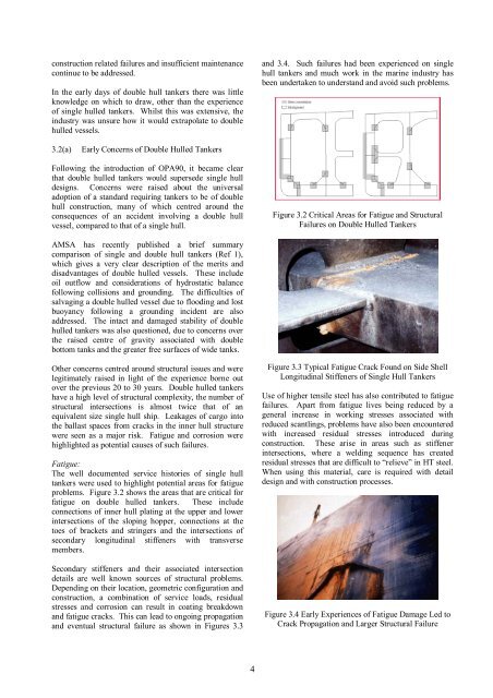
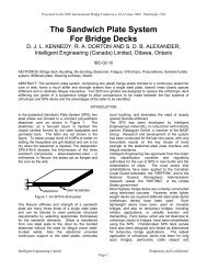
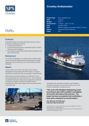
construction related failures <strong>and</strong> insufficient maintenancecontinue to be addressed.In the early days <strong>of</strong> double hull tankers there was littleknowledge on which to draw, other than the experience<strong>of</strong> single hulled tankers. Whilst this was extensive, theindustry was unsure how it would extrapolate to doublehulled vessels.<strong>and</strong> 3.4. Such failures had been experienced on singlehull tankers <strong>and</strong> much work in the marine industry hasbeen undertaken to underst<strong>and</strong> <strong>and</strong> avoid such problems.3.2(a)Early Concerns <strong>of</strong> Double Hulled TankersFollowing the introduction <strong>of</strong> OPA90, it became clearthat double hulled tankers would supersede single hulldesigns. Concerns were raised about the universaladoption <strong>of</strong> a st<strong>and</strong>ard requiring tankers to be <strong>of</strong> doublehull construction, many <strong>of</strong> which centred around theconsequences <strong>of</strong> an accident involving a double hullvessel, compared to that <strong>of</strong> a single hull.Figure 3.2 Critical Areas for Fatigue <strong>and</strong> StructuralFailures on Double Hulled TankersAMSA has recently published a brief summarycomparison <strong>of</strong> single <strong>and</strong> double hull tankers (Ref 1),which gives a very clear description <strong>of</strong> the merits <strong>and</strong>disadvantages <strong>of</strong> double hulled vessels. <strong>The</strong>se includeoil outflow <strong>and</strong> considerations <strong>of</strong> hydrostatic balancefollowing collisions <strong>and</strong> grounding. <strong>The</strong> difficulties <strong>of</strong>salvaging a double hulled vessel due to flooding <strong>and</strong> lostbuoyancy following a grounding incident are alsoaddressed. <strong>The</strong> intact <strong>and</strong> damaged stability <strong>of</strong> doublehulled tankers was also questioned, due to concerns overthe raised centre <strong>of</strong> gravity associated with doublebottom tanks <strong>and</strong> the greater free surfaces <strong>of</strong> wide tanks.Other concerns centred around structural issues <strong>and</strong> werelegitimately raised in light <strong>of</strong> the experience borne outover the previous 20 to 30 years. Double hulled tankershave a high level <strong>of</strong> structural complexity, the number <strong>of</strong>structural intersections is almost twice that <strong>of</strong> anequivalent size single hull ship. Leakages <strong>of</strong> cargo intothe ballast spaces from cracks in the inner hull structurewere seen as a major risk. Fatigue <strong>and</strong> corrosion werehighlighted as potential causes <strong>of</strong> such failures.Fatigue:<strong>The</strong> well documented service histories <strong>of</strong> single hulltankers were used to highlight potential areas for fatigueproblems. Figure 3.2 shows the areas that are critical forfatigue on double hulled tankers. <strong>The</strong>se includeconnections <strong>of</strong> inner hull plating at the upper <strong>and</strong> lowerintersections <strong>of</strong> the sloping hopper, connections at thetoes <strong>of</strong> brackets <strong>and</strong> stringers <strong>and</strong> the intersections <strong>of</strong>secondary longitudinal stiffeners with transversemembers.Secondary stiffeners <strong>and</strong> their associated intersectiondetails are well known sources <strong>of</strong> structural problems.Depending on their location, geometric configuration <strong>and</strong>construction, a combination <strong>of</strong> service loads, residualstresses <strong>and</strong> corrosion can result in coating breakdown<strong>and</strong> fatigue cracks. This can lead to ongoing propagation<strong>and</strong> eventual structural failure as shown in Figures 3.3Figure 3.3 Typical Fatigue Crack Found on Side ShellLongitudinal Stiffeners <strong>of</strong> Single Hull TankersUse <strong>of</strong> higher tensile steel has also contributed to fatiguefailures. Apart from fatigue lives being reduced by ageneral increase in working stresses associated withreduced scantlings, problems have also been encounteredwith increased residual stresses introduced duringconstruction. <strong>The</strong>se arise in areas such as stiffenerintersections, where a welding sequence has createdresidual stresses that are difficult to “relieve” in HT steel.When using this material, care is required with detaildesign <strong>and</strong> with construction processes.Figure 3.4 Early Experiences <strong>of</strong> Fatigue Damage Led toCrack Propagation <strong>and</strong> Larger Structural Failure4
Corrosion:Undetected corrosion has been a major cause <strong>of</strong> some <strong>of</strong>the most noteworthy marine disasters. A paper producedby OCIMF (Ref 2) provides a very concise summary <strong>of</strong>the potential problems facing the operators <strong>of</strong> doublehulled tankers. In particular it highlights the difficulties<strong>of</strong> coating, inspecting <strong>and</strong> maintaining the ballast spaces,which in conventional steel designs are cellular, with acomplex arrangement <strong>of</strong> internal stiffeners, brackets <strong>and</strong>associated structural details. In today’s double hulledtankers it is common practice to provide full coating <strong>of</strong>the ballast tanks, but to coat only the bottoms <strong>of</strong> cargotanks. A second paper by OCIMF (Ref 3) provides avery clear view <strong>of</strong> the various sources <strong>of</strong> corrosionaffecting tankers <strong>and</strong> their influence on corrosion rates.<strong>The</strong>se include coatings, washing processes, sulphurcontent <strong>of</strong> cargo, inert gas quality, construction materials<strong>and</strong> others.It is clear that control <strong>of</strong> corrosion plays a major part inthe safe operation <strong>and</strong> maintenance <strong>of</strong> a double hulledtanker. Conventional steel designs, with their inherentcomplexity are costly to protect <strong>and</strong> maintain. This isdue to the large surface areas, difficulty <strong>of</strong> access <strong>and</strong>large numbers <strong>of</strong> points for potential initiation <strong>of</strong> coatingbreakdown.Experience <strong>of</strong> double hulled tankers to date:To date there is little documented operational experienceon the structural performance <strong>of</strong> double hulled tankers.Anecdotal evidence suggests that the experience has s<strong>of</strong>ar been satisfactory. Whilst there are cases <strong>of</strong> minorstructural failures, such as fatigue cracks in stiffenerintersections <strong>and</strong> inner hull connections with the slopinghopper, these have been found <strong>and</strong> addressed with nomajor incidents. Regular inspection <strong>and</strong> maintenanceremains a clear necessity.A paper by Bergesen, produced in 2000 (Ref 4) providesa comprehensive summary <strong>of</strong> experience in operatingthree double hulled VLCCs. <strong>The</strong> paper concludes with anumber <strong>of</strong> measures for protecting both ballast <strong>and</strong> cargotanks from corrosion. <strong>The</strong> paper also notes that waveloads on the bow have resulted in local buckling <strong>of</strong>internal structure <strong>and</strong> hull plating deformation, resultingin a “starved horse” appearance.Today’s double hulled tankers are not known to besuffering from structural failures. However, the effortrequired to design <strong>and</strong> construct intersections with goodservice performance adds considerably to the productioncost <strong>and</strong> the problems have not been completelyeliminated.3.3 USE OF <strong>SPS</strong> IN DOUBLE HULLED TANKERSIntelligent Engineering believes that <strong>SPS</strong> technology willprovide improved safety through greater resistance toimpact, collisions, fire <strong>and</strong> explosion. Furthermore, thestructural simplification that <strong>SPS</strong> provides will givecommercial benefits in terms <strong>of</strong> reduced costs forproduction, inspection <strong>and</strong> lifetime maintenance. Byremoving secondary stiffeners from the structure, thehigh risk areas <strong>of</strong> coating breakdown, acceleratedcorrosion <strong>and</strong> fatigue cracking are eliminated.3.3(a)Design principles in using <strong>SPS</strong>Using <strong>SPS</strong> in ship structures requires a fresh view ondesign, especially in areas <strong>of</strong> structural intersections.Basic longitudinal strength is assessed in a similar way tocurrent established methods, using classic navalarchitecture theory <strong>and</strong> st<strong>and</strong>ard hull section propertycalculations. With <strong>SPS</strong> structures, the continuous inner<strong>and</strong> outer face plates <strong>of</strong> the composite s<strong>and</strong>wich areincluded in the section properties, but the elastomer coreis not included in the calculation. Depending on localstrength requirements, a portion <strong>of</strong> the steel area, aboutthe neutral axis, may be redistributed to the deck <strong>and</strong>outer hull to maintain the section modulus whilereducing overall weight.<strong>SPS</strong> design for local strength involves a new approach.Conventional ship structures are commonly designedusing established ‘empirical’ classification society rules.<strong>The</strong>se do not yet exist for <strong>SPS</strong> structures, which behaveas true composite materials with isotropic properties.Design assessment rules for s<strong>and</strong>wich plate shipstructures are being developed by Lloyd’s Register <strong>and</strong>are expected in draft form in 2005.<strong>The</strong> scantlings <strong>of</strong> <strong>SPS</strong> plating are generally in the range<strong>of</strong> 3 mm to 8 mm for the steel face plates <strong>and</strong> 20 mm to50 mm for the core thickness. <strong>The</strong> required scantlingsare a function <strong>of</strong> the loads <strong>and</strong> spacing <strong>of</strong> the supportingframing, <strong>and</strong> are currently determined by direct designcalculations, using normal stress criteria for yield <strong>and</strong>shear. Corrosion margins are added to the face plates, asrequired.<strong>SPS</strong> panels are very stable, since the stiff elastomer coreprevents local buckling effects. Semi-empiricalequations have been developed to determine the in-planeload carrying capacity for any combination <strong>of</strong> transverseloads. <strong>The</strong>se have been verified using full scale tests <strong>and</strong>non-linear finite element analyses. Current designpractice uses finite element analysis to check the in-planeload carrying capacity <strong>of</strong> <strong>SPS</strong> panels. This is achievedwith models using solid or layered shell elements toaccount for both material <strong>and</strong> geometric non-linearity.<strong>The</strong> maximum transverse framing should be in the rangebetween 3.2 to 4.0 m. <strong>SPS</strong> plating should have an aspectratio (the ratio <strong>of</strong> length <strong>of</strong> the long to short pl<strong>and</strong>imension) between 1.4 <strong>and</strong> 1.7, to produce an economicplate with the maximum buckling strength. <strong>SPS</strong> panelsshould be arranged so that the largest dimension isaligned along the length <strong>of</strong> the ship.5