Directional Control Air Valves & Accessories
Directional Control Air Valves & Accessories
Directional Control Air Valves & Accessories
- No tags were found...

Create successful ePaper yourself
Turn your PDF publications into a flip-book with our unique Google optimized e-Paper software.
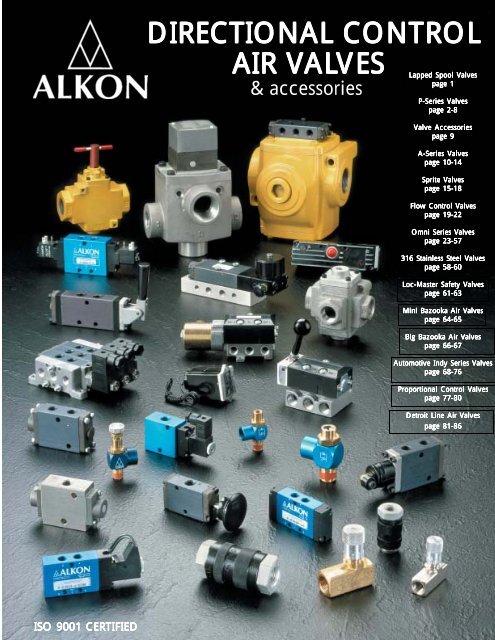
DIRECTIONAL CONTROLDIRECTIONAL CONTROLAIR VALALVESLapped Spool Vpage 1AIR VALVES& accessories& accessoriesLapped Spool <strong>Valves</strong>P-Series <strong>Valves</strong>page 2-8Valve <strong>Accessories</strong>page 9A-Series <strong>Valves</strong>page 10-14Sprite <strong>Valves</strong>page 15-18Flow <strong>Control</strong> <strong>Valves</strong>page 19-22Omni Series <strong>Valves</strong>page 23-57316 Stainless Steel <strong>Valves</strong>page 58-60Loc-Master Safety <strong>Valves</strong>page 61-63Mini Bazooka <strong>Air</strong> <strong>Valves</strong>page 64-65Big Bazooka <strong>Air</strong> <strong>Valves</strong>page 66-67Automotive Indy Series <strong>Valves</strong>page 68-76Proportional <strong>Control</strong> <strong>Valves</strong>page 77-80Detroit Line <strong>Air</strong> <strong>Valves</strong>page 81-86ISO 9001 CERTIFIED
SERIES P VALVESLAPPED SPOOL VALVESThe heart of the Series P valve is the packless bodyand spool assembly constructed of aluminum witha ceramic hard aluminum oxide finish. This uniquecartridge and spool assembly is completely isolatedfrom external forces; is pressure balanced, allowingany port to be pressurized or subjected to backpressure with no effect on shifting force, and hasbeen designed to meet the most stringent requirementsthat today’s customers demand. All SeriesP valves are inline, and all can be manifolded. Thisseries is manufactured to the highest quality standardsin the industry today and all carry a three yearwarranty on all parts of the valve, including the coil.No lubrication; extremely fast shifting coupled withvery low minimum pilot pressure, a variety ofoptions and all at a low cost.CONSTRUCTION:• Body, End Caps & Manifolds: AnodizedAluminum• Cartridge & Spool: Hard Coated Aluminum• Coils: Molded Nylon• O-Rings: Buna N (Nitrile)LUBRICATION:NONE REQUIRED - However a general purposelubricating oil may be used if desired. In thesecases, we recommend ASTM/ISO viscosity GradeFILTRATION:A 40 micron filter is recommended.32.WARRANTY:Series P valves are covered by a three yearwarranty from date of purchase.Series A & Spriteare covered by a 90-day warranty. All provisionsof our standard warranty policy (available uponrequest) apply.OPERATING PRESSURES:• Internal Pilot (Standard): 10 P.S.I. to 150 P.S.I.• External Pilot: Vacuum to 150 P.S.I.NOTE: External Pilot Supply of at least 10 P.S.I.required for vacuum service.MOUNTING:All Series P <strong>Valves</strong> have no limitations as far asthe orientation of the valve. Coils can be rotatedin any direction for ease of installation.CYCLE RATE:Series P <strong>Valves</strong> may be cycled at over 2000cycles per minute in most applications.OPTIONS:Include hard wired coils; factory assembly ofvalves to manifolds; a variety of plug connectors;pre-installed AQ push-in fittings, and many otherpopular options.SERIES A & SPRITE VALVESSeries P Spool AssemblyAlkon Series A and Sprite II valves have been designed to comply with the ever more stringentrequirements for increased production rates through higher speeds and component reliability.The heart of these valves is a packless spool body and spool assembly constructed of aluminumwith a ceramic hard aluminum oxide finish. Ground and matched to precision tolerances, its operationis virtually frictionless.Benefits of this packless design begin with the elimination of dynamic seals and their incumbentdifficulties. Fast response allows increased machine cycle rates; non-lube operation reduces scheduledmaintenance requirements. The body and spool assembly is pressure balanced, allowing any port tobe pressurized or subjected to back pressure with no effect on spool shifting force. Exhaust portmufflers or speed controls may be used with no effect on valve response.The unique body and spool assembly has been completely isolated from external forces by use of apatented 3-point suspension. This assembly, coupled with a complete variety of actuators andmounting alternatives, provides the highest level of performance and versatility found in the air valveindustry.12VALVE FEATURES• Packless design• Fast Response• Operate with or without lubrication• Can be subbase, manifold or cylinder mounted
SERIES P-FW/MW MINIATURE 3-WAY VALVESGENERAL INFORMATION:• Anodized Aluminum Body for acorrosion resistant, lightweightpackage• Mount as a single station valve orstack into a manifold of up to 15stations• Options include hard wired coils,non-locking manual override anda variety of plug connectors• Can easily be converted to a twowayvalve simply by plugging theexhaust port• Coils can be rotated in 90 oincrements• Choice of two flow modelsSPECIFICATIONS:• Operating Temperature:0 o to 125 o• Operating Pressure:Vacuum to 150 P.S.I.• Cv Rating:FW Cv .085 (Approx. 4 SCFM)MW Cv .16 (Approx. 8 SCFM)• Weight:Approximately 4.3 oz• Normally closedPFWPMW.085 Cv.160 CvFEATURES:• Choice of 1/8 NPT or1/4 NPT• Standard Locking TypeManual Override• Direct Acting Solenoid• Three Year Warranty• Bottom mounting holesSERIES P-FW/MW MINIATURE 3-WAY VALVESPART # A B C Sq. D E F G H J KP-FW1/MW1 .766 .422 1.000 .094 3.250 .562 .125 .500 1/8 NPT 1/8 NPTP-FW2/MW2 1.000 .500 1.125 .125 3.593 .625 .125 .625 1/4 NPT 1/4 NPTSIMPLE HOW-TO-ORDER INSTRUCTIONSP- FW1 S S 115/60 N LSERIES MODEL FUNCTION VOLTAGE OPTIONSP FW1 SS 6 VDC 24/60 NL - Non Locking OverrideFW2 12 VDC 115/60 N4 - Nema 4 OperatorMW1 24 VDC 230/60 FA - Factory Assembly StackMW2 (Specify # of Stations)Plug Connections: See P-070/140 on Page 732
SERIES P-MC 3-WAY VALVESGENERAL INFORMATION• Compact size• Variety of combinations• In line design - or mount on manifold• Normally open or normally closed models• 1/8 NPT or 1/4 NPT ports• Cv - .5 (1/8”) or .85 (1/4”)• Cycle Rate - Up to 2,500 per minute• Standard locking manual overrideSIMPLE HOW-TO-ORDER INSTRUCTIONSP-M C 1 SS 115/60 HWSERIES TYPE SIZE FUNCTION VOLTAGE OPTIONSP MC (NC) 1 (1/8 NPT) SS-Single Solenoid 6 VDC 24/60 HW - Hard Wire Coil LeadsMO (NO) 2 (1/4 NPT) SP-Single Pilot 12 VDC 115/60 FA - Factory Assembly of Manifolds24 VDC 230/60 XP - External Pilot Supply PortMANIFOLDS: Available from 2 to 10 stationsP-MC1: Part # 22029 - (# of stations)P-MC2: Part # 22046 - (# of stations)BLOCKING PLATE: To block off manifold stationP-MC1: Part # 22060P-MC2: Part # 22061LOW WATTAGE SOLENOID:Consult factorySURGE SUPPRESSORS:Consult factoryDIMENSIONSCONNECTORS:Part # 21876: Standard ConnectorPart # 21878: Standard Connectorwith pre-wired 3 ft. leadsPart # 21905 - ( ): Lighted Connector (Voltage)Part # 21906 - ( ): Lighted Connector (Voltage)with pre-wired 3 ft. leadsPart # 22076: Standard Connectorwith pre-wired 6 ft. leadsUSE FOLLOWING VOLTAGE CODES:For lighted connectors6 VDC - 01 12 VDC - 02 24 VDC - 0324/60 - 05 115/60 - 06 230/60 - 07MODEL# A B C D E F G H J K LP-MC1 .961 4.25 1.188 1.56 .961 .500 1.75 .750 .218 .266 1/8P-MC2 .961 4.25 1.375 1.88 .961 .500 1.875 1.00 .200 .400 1/4MANIFOLDSMODEL# A B C D E F G H J3P-MC1 .875 .812 2.562 .200 .812 2.00 .415 1.00 1/4P-MC2 .968 1.063 3.00 .188 .812 2.00 .415 1.00 1/4
SERIES P-035 4-WAY VALVES• 1/8 NPT Ports• Cv - .4• Cycle rate - Up to 2,500 per minute• Standard locking manual overdriveSIMPLE HOW-TO-ORDER INSTRUCTIONSP- 035 S S 115/60 HWSERIES MODEL FUNCTION VOLTAGE OPTIONSP 035 SS (Single Solenoid) 6 VDC 24/60 HW - Hard Wire Coil LeadsDS (Double Solenoid) 12 VDC 115/60 FA - Factory Assembly of ManifoldsSP (Single Pilot) 24 VDC 230/60 XP - External Pilot Supply PortDP (Double Pilot)3S (3 POS., DS,all ports blocked)3P (3 POS., DP,all ports blocked)MANIFOLDS: Available from 2 to 10 stationsPart # 21904 - (# of stations)BLOCKING PLATE: To block off manifold stationPart # 21908INTERFACE PLATE: For mounting a P-035 to aP-070 manifold - Part # 21910CONNECTORS:Part # 21876: Standard ConnectorPart # 21878: Standard Connectorwith pre-wired 3 ft. leadsPart # 21905 - ( ): Lighted Connector (VoltagePart # 21906 - ( ): Lighted Connector (Voltage)with pre-wired 3 ft. leadsPart # 22076: Standard Connectorwith pre-wired 6 ft. leads)LOW WATTAGE SOLENOID:Consult factorySURGE SUPPRESSORS:Consult factoryUSE FOLLOWINGVOLTAGE CODES:For lighted connectors6 VDC - 01 12 VDC - 02 24 VDC - 0324/60 - 05 115/60 - 06 230/60 - 074
SERIES P-070 / P-140 4-WAY VALVESGENERAL INFORMATION:• High flow Multi-Purpose Design• Use as a 3 Way by plugging one port• In line design - or mount on manifold• Single or double solenoid or pilot• Two or three position models available• P-070: 1/4” Ports Cv - .8• P-140: 3/8” Ports Cv - 1.5• Cycle Rate - over 2,000 per minute• Standard non-locking manual override• Wide variety of popular optionsP-070Hand Lever ValvePart # P-070-HLThe P-070 is available in a Hand LeverVersion that is compact and versatile.The standard is a spring return modelthat may be converted to a detentedmodel simply by turning two allenscrews in the end cap.SIMPLE HOW-TO-ORDER INSTRUCTIONSP- 070 S S 115/60 HWSERIES MODEL FUNCTION VOLTAGE OPTIONSP 070 SS (Single Solenoid) 6 VDC 24/60 HW - Hard Wire Coil Leads140 DS (Double Solenoid) 12 VDC 115/60 FA - Factory Assembly of ManifoldsSP (Single Pilot) 24 VDC 230/60 XP - External Pilot Supply PortDP (Double Pilot)LM - Locking Manual Override3S (3 POS., DS,N4 - NEMA 4 Operatorall ports blocked)3P (3 POS., DPall ports blocked)Consult factory for other available combinationsMANIFOLDS: Available from 2 to 10 stationsP-070: Part # 21821 - (# of stations)P-140: Part # 21907 - (# of stations)BLOCKING PLATE: To block off manifold stationP-070: Part # 21822P-140: Part # 21909SURGE SUPPRESSORS:Consult factory5CONNECTORS:Part # 21823: Standard ConnectorPart # 21839: Standard Connectorwith pre-wired 3 ft. leadsPart # 21824 - ( ): Lighted Connector (Voltage)Part # 21840 - ( ): Lighted Connector (Voltage)with pre-wired 3 ft. leadsPart # 21852: 1/2 NPT Conduit ConnectorPart # 21841 - ( ): Connector (Voltage)with molded 3 ft. leadsPart # 21842 - ( ): Lighted Connector (Voltage)with molded 3 ft. leadsPart # 22078: Standard Connectorwith pre-wired 6 ft. leadsUSE FOLLOWINGVOLTAGE CODES:For lighted connectors6 VDC - 01 12 VDC - 02 24 VDC - 0324/60 - 05 115/60 - 06 230/60 - 07
SERIES P - 4 WAY VALVESDIMENSIONSMODEL# A1 A2 B C D E F1 G1 G2 H1 J1P-035 4.58 6.88 .750 1.50 .594 .325 1/8 NPT 2.77 3.26 #4 10-32P-070 5.16 7.80 1.00 2.00 .750 .359 1/4 NPT 3.14 3.75 #6 1/8P-140 6.01 8.77 1.25 2.50 1.00 .435 3/8 NPT 3.99 4.73 #8 1/8MANIFOLDSMODEL# PART#P-035 21904P-070 21821P-140 21907A B C D E F G H J K L M P2.50 1.25 .812 .938 .250 .390 2.688 #6 1.000 .781 .344 .656 1/42.50 1.25 1.125 1.062 .250 .400 3.250 #8 1.250 .800 .500 .875 1/43.00 1.50 1.375 1.344 .344 .461 4.062 #10 1.750 .922 .594 1.156 3/86
SERIES P - 4 WAY VALVESMANIFOLD ASSEMBLY:Manifolds can be purchasedseparately or valves can beassembled to them at thefactory.Hardened mounting pins (2)are screwed into the valvebody (5) until flush, and thenthe valve unit is inserted intothe manifold block (4) afterpositioning the o-rings (1).By tightening the allen headscrews (3), the valves areseated and connected to themanifold block. This uniquemethod assures a leak proofassembly. When manifolds arepurchased separately, each kitcontains mounting pins, setscrews and o-rings for thepurchased number of stations.CONNECTORS:In addition to the standard connectors and coils shown (see individualvalve packages for part numbers), we also offer custom configurationssuch as different length cords, lighted wafers, light adapters, green orred LED’s, and a variety of others. Contact your local Alkon distributorfor more information.ELECTRICAL CHARACTERISTICSINRUSH HOLDING NOMINAL POWERVOLTAGE (AMPS) (AMPS) CONSUMPTION6VDC .240 .240 2.9W12VDC .240 .240 2.9W24VDC .108 .108 2.6W24/60 .340 .210 3.8W115/60 .070 .044 3.8W230/60 .040 .024 3.8WRESPONSEMODEL TIME TO TIME TOTYPE ENERGIZE DE-ENERGIZEA.C. SOL. 7 MS 18 MSD.C. SOL. 10 MS 18 MSPILOT 6 MS N/AREPLACEMENT COILSP-035 - P-MC P-070/140 - P-FW P-MWVOLTAGE STANDARD HARD WIRE STANDARD HARD WIRE STANDARD HARD WIRE6 VDC 21874-01 21875-0112 VDC 21874-02 21875-0224 VDC 21874-03 21875-0324/60 21874-05 21875-05115/60 21874-06 21875-06230/60 21874-07 21875-0721832-01 21833-0121832-02 21833-0221832-03 21833-0321832-05 21833-0521832-06 21833-0621832-07 21833-0722071-01 22065-0122071-02 22065-0222071-03 22065-0322071-05 22065-0522071-06 22065-0622071-07 22065-077
SERIES PM 3-WAY VALVESNormally Closed, 10/32” Ports, Toggle; Push Button; CamActuators, and a Variety of Porting OptionsGENERAL INFORMATION:MATERIALSBODY: Anodized AluminumSTEM: AcetalSPRING: Stainless SteelBUTTONS/TOGGLES: NylonSEALS: Buna-NOPERATING PRESSURE0 TO 125 P.S.I. <strong>Air</strong>OPERATING TEMPERATURE-20F To +160F (-28C to +71C)FUNCTION3-Way, Normally ClosedFLOW RATEApproximately 10 SCFMat 100 P.S.I.ACTUATING FORCE2 lbs. to 3.5 lbs.PORTINGINLET: Bottom PortOUTLET: Port nearest inletEXHAUST: Port nearest actuatorCam ActuatorPart # PM-CA-1Acetal roller on a nickel plated arm.Mounts to any push button (above)with 5/64” spacer - other types areavailable.Right Angle Mounting BracketPart # PM-MB-1Use to mount any PM Series Valve.Also available in a flat version.8
VALVE ACCESSORIESThe dual exhaust and balanced design of the Alkon valve allows for the use ofinexpensive exhaust metering valves. When screwed into the exhaust ports, theyindependently control the actuator speed in either or both directions.Metering valves have aluminum bodies and steel adjusting screws.Mufflers are used to silence the noise caused by exhausting air. Both standardmufflers and speed control mufflers are made of brass and sintered bronze.MODELDIMENSIONSCvNo. DESCRIPTION Wt. A B C D FACTORSERIES ISIPART No.6661 1/4 NPT Metering Valve 1/2 oz. 1/4 .562 1.437 - 1.007985 3/8 NPT Metering Valve 1 oz. 3/8 .687 1.812 - 1.55ER-50 1/2 NPT Metering Valve 4 oz. 1/2 .875 2.0 - 1.75 -40A01081 #10-32 Exhaust Breather 1/2 oz. 10-32 .312 .40 - .209516-1 1/8 NPT Muffler 1 oz. 1/8 .437 1.125 - .529516-2 1/4 NPT Muffler 2 oz. 1/4 .562 1.375 - 1.109516-3 3/8 NPT Muffler 3 oz. 3/8 .687 1.500 - 1.609516-4 1/2 NPT Muffler 4 oz. 1/2 .875 1.875 - 3.209516-6 3/4 NPT Muffler 5 oz. 3/4 1.062 2.250 - 5.109516-8 1 NPT Muffler 6 oz. 1 1.312 2.875 - 10.09564-1 1/8 NPT Speed <strong>Control</strong> Muffler 2 oz. 1/8 .562 1.375 2.000 .599564-2 1/4 NPT Speed <strong>Control</strong> Muffler 3 oz. 1/4 .625 1.562 2.187 .779564-3 3/8 NPT Speed <strong>Control</strong> Muffler 4 oz. 3/8 .687 1.875 2.813 1.319564-4 1/2 NPT Speed <strong>Control</strong> Muffler 5 oz. 1/2 .875 2.250 3.312 2.60SCS-34 3/4 NPT Speed <strong>Control</strong> Muffler 7 oz. 3/4 1.062 2.375 - 4.80SCS-100 1 NPT Speed <strong>Control</strong> Muffler 9 oz. 1 1.312 2.500 - 8.50ER25ER37ER-5040A01081MF18MMF14MMF38MMF12MMF34MMF100MSCS-18SCS-14SCS-38SCS-12SCS-34SCS-1009
SERIES A VALVESSolenoid <strong>Control</strong>led / Pilot OperatedReliably rapid response is inherent to the Series A valve’s design concept. The lowfriction operation, short spool travel and low mass spool all represent constructionfeatures that make fast response possible.Equally important, this fast response is repeatable. It does not fluctuate whendegree of lubrication, operating pressure or internal valve back pressure vary.Fast, repeatable response translates into immediate benefits for the machinedesigner. Now, machine cycle rates can be increased to match the valve’s instantresponse to control signals.Horizontal and Vertical Solenoid OperationSolenoid/Pilot operators are available in either horizontal or vertical configurationsto accommodate varying space limitations.The horizontal model is usually used for sub-base and cylinder mounting; thevertical for manifold mounting since it provides access to the manifolds side cylinderports.Series A solenoid operators offer a wide variety of voltages and frequencies; all coilsare continuously rated, and continous cycle rates up to 300 CPM can be maintained.Options• Molded coils• Locking type manual override• Two position detent (adds 5/8” to overall length)• 1/4 NPT threaded pilot exhaust adapter• External pilot supplyModel 7900, SingleHorizontal Solenoid/Pilot OperatedNOTE: Three position open or closed center valves are available as special assemblies.Consult factory.HorizontalModel 7980, DoubleHorizontal Solenoid/Pilot OperatedVerticalModel 8060, SingleVertical Solenoid/Pilot OperatedModel 8065, DoubleVertical Solenoid/Pilot Operated10
Model A 7902,SingleSolenoidPilot OperatedSERIES A VALVESSprite Valve ActuatorSPRITE solenoid/pilot operators are available for single or double actuationapplications in horizontal configurations.The SPRITE actuator offers lapped -spool reliability in both valve and operator,providing a maintenance-free product life measured in multi-millions of cyclescurrently unobtainable from standard pilot/solenoid operators.Offered in a wide variety of voltages and frequencies; all coils are rated forcontinuous or maintained signal service and continuous repeatable cycle ratesin excess of 3000 CPM are possible. Molded coils are standard and solenoidhousings meet most JIC and NEMA IV criteria. Non-locking manual override isstandard.Options• Two position detent (adds 5/8” to overall length)NOTE: Three position open or closed center valves are available as special assemblies.Consult factory.Model A 7982,Double SolenoidPilot OperatedModel 7984Single PilotOperated<strong>Air</strong> PilotIn applications where electrical controls are not suitable, or where they arehazardous, air pilot operated valves can be used. These valves can also be appliedfor special purpose circuitry such as sequencing or timing operations.Since the low friction characteristics of the body and spool assembly requires only.50 psig to shift, vacuum can be considered as a signal source. <strong>Air</strong> pilot operatedvalves, do however require external valves to supply the required signal pressure.Options• Two position detent (adds 5/8” to overall length)NOTE: Three position open or closed center valves are available as special assemblies.Consult factory.Model 7986Double PilotOperated11
SERIES A VALVES<strong>Air</strong> Bleeder OperatedBleeder OperatedBoth air pilot and bleeder operated valves can be applied when electrical control isimpractical or hazardous. The bleeder can be used in place of the air pilot modelwhere limited space prohibits the external pilot pressure supply required by theexternal pilot control valves.Bleeder Operators#6000, Plunger type bleeder operator is used when striking force is straight on.#8492, Ball type bleeder operator has a hardened ball for cam actuation.Options• Two position detent (adds 5/8” to overall length)Model 7919<strong>Air</strong> Bleeder OperatedIntegrated Power PackageThe integrated power package is a subbase assembly in which the Series A valveis assembled directly to any square head tie rod type air cylinder.Since only one air supply connection is required, assembly times can be greatlyreduced. AC sub-bases include metering valves and muffler to keep the IntegratedPower Package a neat, compact cylinder and valve combination. The AC valveincreases the overall height of the cylinder by only 3 inches.12
SERIES A VALVESManual and Mechanically OperatedAvailable with either hand, foot or palm button actuators, manually operatedSeries A valves can be used directly as power valves to control air actuators orindirectly to operate larger pilot operated hydraulic or pneumatic valves.Hand or foot operated models are available with spring offset or with optional twoposition detent.Three position, spring centered or detented, open or closed center hand valves areavailable as special assemblies. Consult factory.Actuating force of palm button is only 2 lbs.Mechanically OperatedThe mechanically operated Series A is a ball cam operated valve. It can be used asa power valve to control air actuators or to control larger pilot operated hydraulic orpneumatic valves.• Stroke: .250”• Shifting force: 3.85 lbs. minimum• Allowable override: .093 with 10.4 lb. maximum force• Maximum allowable cam rise: 30 0 (including 1/32 override)Model 7987Hand Lever OperatedModel 7988Foot Pedal OperatedModel 7990Palm Button OperatedModel 8084Ball Cam OperatedMultiple Station ManifoldsSeries A valves may be manifold mounted in a flexible arrangement which allowsthe stacking of any number of valves in any combination of actuators.With multiple manifold assembly, only one inlet connection is required for the entiremanifold assembly.The exhaust port on the manifold is also common to all valves in the assembly.Both inlet and exhaust ports are 1/2 NPT. Cylinder ports are available in either 1/4or 3/8 NPT. All manifold bases are provided with side and bottom cylinder ports andare shipped with the bottom cylinder ports plugged unless otherwise specified.13
SERIES A VALVESSolenoid / Pilot Valve Specifications• Operating Pressure (std.): 20 - 175 psig• Operating Pressure (with optional external pilot supply: Vacuum - 250 psig)• Maximum allowable cycle rate: 300 CPM (to 600 CPM under specified conditions)• Maximum heat rise: 85 o CResponse CharacteristicsTime to Time toModel Shift in Fill 10 in 3Size Type Milli- ChamberSeconds* to 80 PSI1/4”Sub-base3/8”De-energizationStart toUnloadUnload to20 PSI**Single Sol. 9 22 22 33Double Sol. 9 20 10 30Single Sol. 9 21 20 31Sub-base Double Sol. 9 19 10 29For models A7902 and A7982 refer to SPRITE IIElectrical CharacteristicsNominalInrush Holding PowerVoltage (Ma) (Ma) Consumption6VDC - 1830 12 watts12VDC - 790 12 watts24VDC - 396 12 watts24/60 1250 835 12 watts115/60 261 174 12 watts230/60 130 87 12 wattsGeneral SpecificationsFlow Characteristics<strong>Air</strong>line Preparation: The Series A valve may be used with dry or lubricated filtered air.Installation: Valve body to sub-base screws should be torqued no more than 24 in./lb.Flow curves shown are for the 1/4” sub-base mounted valves. For 3/8” sub-base, 1/4” or 3/8” manifold valvesuse the noted correction factors, (CF).* Represents time in milliseconds from solenoid actuation to first recorded pressure in chamber. At cylinderport itself, solenoid pilot valves required a maximum of 8 milliseconds.** Represents time from first recorded pressure decay in chamber to unloading down to 20 psig from 100 psiginitial pressure.CV <strong>Valves</strong>Mounting TypeCVValve1/4” Sub-base 1.413/8” Sub-base 1.491/4” Manifold 1.523/8” Manifold 1.57How To Order Series A <strong>Valves</strong>A A 7900 3/8 115/60 M CSeries “A” Pneumatic Valve Model Size VoltageOptionsCode<strong>Directional</strong> Valve (See Pages 10-13) Sub-base 1/4” (If Applicable 2 Position Detent 2P3/8”Specify)External Pilot XPMultiple 1/4”MountingExhaust Adp. EAManifold 3/8”A Sub-baseMolded Coil MC1/8”M Multiple-ManifoldCylinderLess Sub-base LS1/4”C CylinderMountedLess CoilLC<strong>Valves</strong> 3/8”Manual Override MO1/2”Notes:• <strong>Valves</strong> as ordered above will be shipped assembledto sub-base or manifold called out.• If coil voltage is not specified, std. 115/60 willbe furnished.• If no base is required specify option code LS in • Cylinder mount Subbase is furnished with 12”appropriate area of model number. transfer tube as standard.14
SPRITE VALVESHow To Order Sprite II <strong>Valves</strong>3 & 4 Way <strong>Air</strong> <strong>Valves</strong> That Bring a New Concept to<strong>Air</strong> Valve DesignThe Sprite II is truly a unique miniature solenoid air valve. It brings a technologyto pneumatic control that through the years has proven on-the-job reliability in thesmall electrical relay field. This proven technology of solenoid actuation, and Alkon’stime tested lapped spool valve elements combine as the basis of the excitingSprite II valve.The Sprite II valve has been specifically designed to bring a higher level ofreliability to pneumatic equipment, and at the same time a new level of versatilityto system design.• Sub-base mounted. Same valve assembly may be used aloneon its own sub-base or in compact multifunction manifolds.• Simple operation.• Operates with or without line lubrication.• Working pressures to 125 psi.• Continuous duty solenoids.• Integral locating pin for fool-proof valve alignment tosub-base or manifold.• Simple sub-base mounting from top or bottom.An Incredible Response Time and Cycle RateAmazing as it seems, the Sprite II valve can be continuously cycled as fast as alternating current itself- thirty-six hundred times per minute. Of course, that’s far beyond practical cylinder speed, but it doesmake a point about the valves capabilities.Equally impressive is the response time - from closed to full open in just 6.0 milliseconds. That initself is quite out of the ordinary.Simple, Wear-free OperationThe extraordinary performance of Sprite II valves is made possible by two major characteristics:1. Exceedingly simple operation that eliminated points of wear or fatigue.2. A virtually frictionless precision matched body and spool assembly that requires only minimal forceto shift.The solenoid operator itself consists of a lightly hinged mechanical operating arm (armature) that’sheld in position by a low tension spring. With the armature in its spring held position, a second lightspring holds the spool in its normal position. When the solenoid is energized, the current creates amagnetic effect on a protruding steel core, which in turn draws the armature toward it. When thesolenoid is de-energized, spring force returns the pressure balanced spool to its original position.The mass of the Sprite II armature is negligible compared to conventional T-bar orpoppet type. This low mass plus the small, highly efficient magnetic gap give theSprite II its exceptional performance characteristics.2 39 R2 115/60 45Series “2” VALVE FUNCTION Single Solenoid VOLTAGE OPTIONSWhen Sub-Base Mtd.When ManifoldMtd.Spring Return“R2”6VDC12VDCMM4SMultiple Manifold1/4” Side Ported Sub-Base“30” Not Used 3-Way; N.C.24VDC4B 1/4” Bottom Ported Sub-Base“39” 3-Way N.C. & N.O. 3-Way; N.O.12V/50-60 Hz8S 1/8” Side Ported Sub-BaseMulti-Function“40”24V/50-60 Hz8B 1/8” Bottom Ported Sub-Base4-Way 4-Way115V/50-60 HzNote:230V/50-60 Hz• Non-Locking Manual Overrides - Standard15 • <strong>Valves</strong> and bases will be shipped separately unless “Factory assembly” is specified on the order.
SPRITE VALVESIt Has Construction Extras, TooSprite II is simply an outstanding valve package designed and constructed with alot of attention to detail, like the spool which is precision machined to formextremely sharp land edges. This in turn gives the valve self-cleaning properties andreduces the stroke required for full flow.You’ll notice, too, that the spool and body are designed as a floating sub-assemblywithin the valve’s protective housing to keep exterior forces from disturbing itsprecision operation.The solenoid cover itself meets the latest industry standards - remove it and thesolenoid comes with it, rendering the valve inoperative. Captive assembly boltseliminate the possibility of lost parts in disassembly.Complete corrosion resistance with aluminum and plated steel internal parts.One hundred percent functional testing of every valve that leaves the factory.SpecificationsSprite II is a direct solenoid operated spool valve, with a short stroke, and packlessdesign, for 3 or 4 way applications. It may be continuously operated with or withoutline lubrication, and mounted in any position. It is a sub-base mounted valve, meaningthe same valve my be mounted to either individual sub-bases, or mounted to amulti-station manifold, from 2 to 12 stations, with any combination of 3 or 4 wayoperations. All solenoids are rated for continuous duty.Pressure Rating: 125 PSI*Response Time: 6.0 MillisecondsCV Rating: 0.23Filtration: 10 micron filter recommendedLubrication: Line lubrication optional, but not necessary*AC Coils - DC Coils are somewhat slower, but response time may beimproved by the use of a <strong>Control</strong>lable Overvoltage Supply.Solenoid DataAll solenoid coils are furnished with 24inch leadwire connections. Coils arevarnished in conformance with MIL-V-173.All voltages shown at right are furnishedat no extra cost. For other voltages, consultfactory. AC coils may be used for either 50cycle or 60 cycle service.AmperageVoltage (Milli-Amps) Wattage6 VDC 460 2.812VDC 230 2.824VDC 115 2.812VAC/50-60Hz 1,600 800 5.224VAC/50-60Hz 800 400 5.2115VAC/50-60Hz 160 80 5.2230VAC/50-60Hz 80 40 5.216
SPRITE VALVESSingle Sub-base MountingBetween the valve and the sub-base is a locating pin which assures accuratealignment of valve and sub-base. <strong>Valves</strong> are secured with two mounting screws.The mounting of this valve may be achieved by one of two methods:1. Sub-base may be bulkhead mounted using 1/4-20 threaded mounting holeson the bottom of the sub-base.2. The same holes are counter-bored from the top of the sub-base to accept #8screws for surface mounting.<strong>Valves</strong> and sub-bases may be ordered separately; however, factory assembly isavailable at a nominal charge.CHART APort IdentificationOperation 1 2 3 43-Way Normally Open Inlet Exhaust Cylinder -3-Way Normally Closed Exhaust Inlet Cylinder3-Way Diverter Cylinder Cylinder Inlet -4-Way Common Exhaust Inlet Exhaust N.C.CylinderN.O.CylinderCHART BSub Base PortingBase Model #3-Way 4-Way Description231S 241S Side Ported, 1/8 NPT232S 242S Side Ported 1/4 NPT231B 241B Bottom Ported 1/8 NPT232B 242B Bottom Ported 1/4 NPT17
SPRITE VALVESMultiple Manifold MountingSprite II is also available for use in compact, multi-function manifolds that offer theadvantages of:• Compact installation• Fewer connections• Faster installationAdditionally, it is one of the few valves available in the industry today that permitsthe combining of 4-way, 3-way, normally open and normally closed functions into asingle manifold assembly.Each manifold services up to twelve valves with only one common inlet and onecommon exhaust port. The common inlet and exhaust ports are 3/8 inchNPT, and cylinder ports are 1/4 inch NPT.When used for manifold mounting, standard Sprite II valves are aligned directly tothe manifold base with a positive locating pin, and connected with two mountingscrews. Manifolds and valves are packaged separately unless specified. Factoryassembly and pressure testing of manifold assemblies are available for nominalcharge.Open stations can be shut off with blanking kits.Versatility - manifolds any combination of 3-way or 4-way valves togetherCompactness - combines 2 to 12 different valves into a compact, multi-function manifoldNOTE: Longer and special manifolds available - Consult FactoryMounting Ease - uses only two easy-access bolts to mount individual valves to manifoldConvenient Porting - manifold services all valves with one common inlet and one commonexhaust port - all cylinder ports located in the same plane for easy piping, neater installationManifold DimensionsManifold No. OfModel No. Stations A B C20806-2 2 4.344 2 -20806-3 3 5.906 4 1.56220806-4 4 7.469 4 3.12520806-5 5 9.031 4 4.68820806-6 6 10.594 4 6.25020806-7 7 12.156 4 7.81320806-8 8 13.719 4 9.37520806-9 9 15.281 4 10.93720806-10 10 16.844 4 12.50020806-11 11 18.406 4 14.06320806-12 12 19.969 4 15.625Valve Port DesignationsValve ModelPort DesignationNo. Description 12230-R2 3 Way N.C. SingleSol. Spring Ret.239-R2 3 Way N.O. SingleSol. Spring Ret.240-R2 4 Way SingleSol. Spring Ret.Not UsedCyl. PortN.C. Cyl.PortCyl. PortNot UsedN.O. Cyl.Port18
FLOW CONTROLSAngle Flow <strong>Control</strong>sAngle Flow <strong>Control</strong> valves aredesigned to provide accurateflow control in a compact, laborsaving package. Features likebuilt in push-in fittings, pre-appliedthread sealant, convenient swiveldesign and unique needle designall add up to a package that willsave time, money and energy whenaccurate control is needed onpneumatic actuators.DESIGN FEATURES:• Choice of built in Series AQpush-in fittings or NPTF connections.• Pre-applied Teflon based threadsealant.• Recessed screw driver adjustmentor optional knurled aluminum knob.• Convenient swivel feature for easeof tubing alignment.• 5 PSI cracking pressure.CONSTRUCTION:• Stem: Brass• Body: Anodized Aluminum• Fitting: Brass• Needle: Stainless Steel• Seals: Buna-NSPECIFICATIONS:• Maximum Operating Pressure:150 PSI• Temperature Range:-10 o F to +160 o F• Low 5 PSI cracking pressure• Use with polyethylene, nylon,or copper tubing, also withpolyurethane 90 durometerand over.OPTIONS:• Electroless Nickel Plated Stem• Viton Seals• BSPT & Metric “OD” Tube Connections• Knurled Aluminum Knob with LocknutFlo-Set <strong>Control</strong> <strong>Valves</strong>Flo-Set flow controls are an effective andaccurate means of controlling the speed ofpneumatic cylinders. They can easily bemounted inline anywhere in your system.A controlled setting of the exhaust port ofthe cylinder allows a set back pressure tosmoothly control piston velocity. They arerecommended for all pneumatic applicationsto 150 PSI.DESIGN FEATURES:• Easily mounted for inline applications.• Anodized aluminum for corrosionprotection.• Knurled sleeve for non-slip adjustment.• Precision fit so vibration will not changeadjusted setting.• Excellent controlled flow and high freeflow.• For sizes 1/4, 3/8, 1/2 and 3/4 NPT.19
FLOW CONTROLSIn-Line Flow <strong>Control</strong>s, Needle & Check <strong>Valves</strong>The Alkon Series J Flow <strong>Control</strong>, Needle and Check <strong>Valves</strong> offer substantially higherflow than any other comparable valve in their size or pressure range. Alkon pioneeredthe two taper needle and the in-line flow path designs to provide the highest flowcoupled with the most sensitive metering from full open to full closed.DESIGN FEATURES:A. Aluminum control knob permits adjustment offlow with valve under pressure.B. Locking set screw on control knob.C. Brass retainer acts as a positive stop for needletravel.D. Buna-N seal standard (Viton seal available) onepieceback-up ring to prevent extrusion.E. Heat treated, ground and polished 416 stainlesssteel needle.F. One-piece, high tensile brass forged body.G. Four stage needle provides the most sensitiveflow metering from full closed to full open.H. Large unobstructed orifices.I. Stainless steel ball acts against a lapped seat toprovide best sealing.J. The stainless steel cage acts as a spring supportball guide and ball stop. The spring is stainlesssteel wire.K. In-line check valve has an orifice larger than thenominal pipe size. Low pressure differential, nochatter and low friction loss.FEATURES FOR DESIGN-IN QUALITY• Positive no-leak stem seal• Safe positive stop for needle travel• Precision calibrated dial to determine and allowa return to required flow settings• Maximum Operating Pressure: 3,000 PSI• 2 PSI check cracking pressure• One piece forged housingOPTIONS• Nickel plating for service with corrosive media• Friction O-Ring for micrometer adjustment• Viton seals• British standard parallel pipe threads• Removable knobNOTE:Patents 3,421,547 and 3,441,24920
FLOW CONTROLSAngle Flow <strong>Control</strong>s, In-Line Flow <strong>Control</strong>s,In-Line Needle & Check <strong>Valves</strong>, Flo-Set Flow <strong>Control</strong>sANGLE FLOW CONTROL WITH SERIES AQ TUBE CONNECTIONPART TUBE PIPE A 1A 2B 1B 2C D E FNO. O.D. THREADJAQ-5/32x2 5/32 1/8 NPT 1.70 2.48 1.28 1.41 .75 .63 9/16 1/2JAQ-4x2 1/4 1/8 NPT 1.70 2.48 1.41 1.55 .75 .63 9/16 1/2JAQ-4x4 1/4 1/4 NPT 1.81 2.61 1.38 1.52 1.06 .75 5/8 1/2JAQ-6x4 3/8 1/4 NPT 1.81 2.61 1.38 1.70 1.06 .75 5/8 1/2JAQ-6x6 3/8 3/8 NPT 2.19 2.83 1.56 2.07 1.16 .88 7/8 1/2JAQ-8x8 1/2 1/2 NPT 2.83 3.72 1.88 2.07 1.44 1.13 1 1/2ANGLE FLOW CONTROL WITH FEMALE PIPE THREADSPART FEMALE MALE A 1A 2B 1C D E FNO. THREAD THREADJPT-2x2 1/8 NPT 1/8 NPT 1.70 2.48 1.28 .75 .63 9/16 1/2JPT-2x4 1/8 NPT 1/4 NPT 1.81 2.61 1.18 1.06 .75 5/8 1/2JPT-4x2 1/4 NPT 1/8 NPT 1.70 2.48 1.41 .75 .63 9/16 1/2JPT-4x4 1/4 NPT 1/4 NPT 1.81 2.61 1.38 1.06 .75 5/8 1/2JPT-4x6 1/4 NPT 3/8 NPT 2.19 2.83 1.50 1.16 .88 7/8 1/2JPT-6x4 3/8 NPT 1/4 NPT 1.81 2.61 1.39 1.06 .75 5/8 1/2JPT-6x6 3/8 NPT 3/8 NPT 2.19 2.83 1.56 1.16 .88 7/8 1/2JPT-6x8 3/8 NPT 1/2 NPT 2.83 3.72 1.75 1.44 1.13 1 1/2JPT-8x8 1/2 NPT 1/2 NPT 2.83 3.72 1.88 1.44 1.13 1 1/2KNURLED ALUMINUM KNOB:Add “K” after first three letters of part number “JAQK” or “JPTK”FLOW CONTROL VALVEMODEL NO. VALVE DIMENSIONS, INCHES C FACTORVBRASSBODYNICKELPLATEDPIPESIZENPTFA B C D E FGHEXSIZECHECKVALVEORIFICENEEDLEVALVEORIFICECHECKVALVENEEDLEFULLOPENAPPROX.WEIGHTJF1 JF1N 1/8 1.468 .562 .913 1.803 .250 .687 3/32 .206 .125 .60 .30 .19JF2 JF2N 1/4 1.937 .687 1.232 2.000 .250 .687 3/32 .281 .187 1.30 .60 .28JF3 JF3N 3/8 2.312 .875 1.545 2.531 .300 .937 3/32 .421 .250 2.85 1.08 .54JF4 JF4N 1/2 3.250 1.187 2.117 3.218 .375 1.250 3/32 .515 .375 4.96 1.75 1.75- JF6N 3/4 4.000 1.750 2.625 3.906 .375 1.250 3/32 .718 .500 9.00 3.20 2.32- JF8N 1 4.000 1.750 2.625 3.906 .375 1.250 3/32 .718 .500 9.20 3.20 2.20IN-LINE NEEDLE VALVEMODEL NO. VALVE DIMENSIONS, INCHES C FACTORVBRASSBODYNICKELPLATEDPIPESIZENPTFA B C D E FGHEXSIZEORIFICENEEDLEFULLOPENJN1 JN1N 1/8 1.468 .562 .913 1.803 .250 .687 3/32 .125 .30JN2 JN2N 1/4 1.937 .687 1.232 2.000 .250 .687 3/32 .187 .60JN3 JN3N 3/8 2.312 .875 1.545 2.531 .300 .937 3/32 .250 1.08JN4 JN4N 1/2 3.250 1.187 2.117 3.218 .375 1.250 3/32 .375 1.75- JN6N 3/4 4.000 1.750 2.625 3.906 .375 1.250 3/32 .500 3.20- JN8N 1 4.000 1.750 2.625 3.906 .375 1.250 3/32 .500 3.2021
FLOW CONTROLSMODEL NO.BRASSBODYIN-LINE CHECK VALVENICKELPLATEDPIPESIZENPFTA B ORIFICE C FACTORVJC1 JC1N 1/8 1.468 .562 .206 .64JC2 JC2N 1/4 1.937 .687 .281 1.35JC3 JC3N 3/8 2.312 .875 .421 3.22JC4 JC4N 1/2 3.250 1.187 .515 4.96- JC6N 3/4 4.000 1.750 .718 9.00- JC8N 1 4.000 1.750 .718 9.20FLO-SET FLOW CONTROL VALVEMODEL A B C DNUMBER NPT INCHES MM INCHES MM INCHES MMFS14 1/4 2 50.8 1-1/16 27.0 1 25.4FS38 3/8 2-29/32 73.8 1-3/8 34.9 1-1/16 27.0FS12 1/2 3-13/32 86.5 1-11/32 42.9 1-3/8 34.9FS34 3/4 4-9/32 108.7 2-1/8 28.6 1-3/4 44.5MODEL NPT CONTROLLED FLOW FREE FLOW CONTROL SCHEDULE 40 AIR PRESS.NUMBER SIZE 0 TO MAX. SCFM ADJ. MAX. SCFM Cv PIPE SCFM PSI1/4 x 2 Nipple30 43 81 40FS14 1/4 39 62 1.1 114 6054 79 174 803/8 x 4 Nipple71 79 140 40FS38 3/8 100 114 2.8 194 60130 149 247 801/2 x 5 Nipple140 147 214 40FS12 1/2 194 206 5.2 302 60247 259 390 803/4 x 6 Nipple242 285 371 40FS34 3/4 340 395 9.2 517 60432 523 697 80The standard cubic feet per minute (SCFM) that the flow control valves will pass exhaust toatmosphere is compared on the chart to the SCFM of air that will flow through a similar sizeand length of standard schedule 40 pipe.22
• OMNI 150• OMNI 250• OMNI 375• OMNI 500DESIGN FEATURES:• Patented Teflon loadedViton “Thin Lip Seal”• Minimum breakout friction• Anodized extruded aluminum• Compact size• 2 and 3 position, 3 and 4 way• Highest flow in industry• Many standard body styles• 50 standard primary operators• Proven performer in bothlubricated and dry systems• Adaptable for vacuum andlow pressures• Operates on standard filtration• Variety of mounting options• Simple to maintainOMNI SERIES VALVESToday’s industrial fluid power operations demand faster, more reliable power andcontrol air valve systems. Alkon’s Omni Series valves meet these needs...A Broad Range of Applications makes the Omni Series best suited for the widestvariety of applications - automation and machine tool control, packaging machinery,robotics clamping, fixtures, cylinder controls, and most other pneumatic devices.Reaction Time is fast and reliable, and will speed your production capability. Forexample, it takes less than 16 milliseconds to shift the valve spool.Superior Performance is guaranteed. Omni Series valves are the fastest, lightest,most compact high-flowing valve packages in the industry. On the basis ofperformance, Omni valves deliver more production per dollar spent.Flexibility is an outstanding feature of all Omni Series valves. <strong>Air</strong> pilot or solenoidoperated, base or manifold mounted, horizontal or vertical stacking or in-linemounting, Omni Series valves can be configured to your specific production ormaintenance requirements.Stacking Feature is another Omni Series advantage. Omni series valves can beassembled into a variety of stacking arrangements to reduce piping requirementsand increase mounting options. These stacks offer high-flow performance in compact,space saving packages. Stacking models have been designed to reduce downtimeand quick and easy valve add-ons, removals or other changes.Omni Series valves are specifically engineered to withstand harshfactory environments. Omni valves are precision-machined,lightweight, compact and corrosion resistant. They’re simple andeasy to maintain, designed for reliable performance and minimumdowntime.PATENTED “THIN LIP” SEAL & SPOOL FEATURES:• Teflon loaded seals provide millions of trouble-free cycles• Unique wiping action eliminates contaminent build-up in bore• Reduces spool hang-up due to compressor or oil varnishingHOW IT WORKS (refer to spool illustration below)A. “Relaxed” no pressure on either side of seal.B. Pressure from right moves seal to left, expanding it against boreto sealed position.C. Force applied to left shifts spool... nominal sealing friction causeslip to flex like diaphram. Flexing action reduces breakdown friction.This spool can react quickly with very low force requirement.23
OMNI SERIES VALVESENGINEERING DATA FOR ALL OMNI VALVESAVAILABILITY2-Way 3-Way 4-Way Inline Stacking Common Base Elect. Explos.Wire Mounting Timers ProofWay150250375Plug3-WayPlug3-WayPlug3-Way• • • •• • • • • • • •• • • • • • • •500Plug4-WayPlug4-Way• • • • • •C v FLOWOPERATORS5.0 5.05004.5 4.54.0 4.03.5 3.53.0 3.02.5 2.52.0 2.01.5 1.51.0 1.0.5 .5150250375OPERATOR REPLACEMENT• For air piloted valves, manual valves, and mechanicallyoperated valves, furnish valve series and operatornumber only.• For solenoid operators, specify voltage as well.EXAMPLE: 375-37 120/60150 = .6CV = 28 SCFM250 = 1.2CV = 56 SCFM375 = 2.3CV = 108 SCFM500 = 5.0CV = 235 SCFM1 SCFM @ 80 PSIG = .073 dm 3 /s24
OMNI SERIES VALVESENGINEERING DATA FOR ALL OMNI VALVESENGINEERING DATAOMNI 150 OMNI 250 OMNI 375 OMNI 500MediaMaximumOperating PressureMin. Pilot PressureSolenoid/SolenoidMin. Pilot PressureSolenoid/SpringMin. Pilot Pressure<strong>Air</strong>/SpringMin. Pilot Pressure<strong>Air</strong>/<strong>Air</strong>Vacuum ToBelow Min. PilotFlow Rate @ 80 PSI(SCFM)Max. Temperature<strong>Air</strong> and <strong>Air</strong> and <strong>Air</strong> and <strong>Air</strong> andinert gasses inert gasses inert gasses inert gasses150 PSI 150 PSI 150 PSI 150 PSI20 PSI 15 PSI 15 PSI 15 PSI45 PSI 40 PSI 45 PSI 45 PSI45 PSI 40 PSI 40 PSI 30 PSI20 PSI 15 PSI 15 PSI 15 PSIAvailable Available Available Available28 56 108 235185 o F 185 o F 185 o F 185 o FFor Other Temps.ConsultFactoryConsultFactoryConsultFactoryPre-lubricated at factory to operate on lubricated or non-lubricated systems.ConsultFactorySOLENOID SPECIFICATIONSOMNI 150 OMNI 250 OMNI 375 OMNI 500Current (Amps)Current (Amps) Current (Amps) Current (Amps)Standard VoltagesIn Rush Holding In Rush Holding In Rush Holding In Rush Holding110/50Hz .09 .04 .13 .08 .13 .08 .13 .08120/60Hz .07 .03 .11 .07 .13 .08 .13 .08215/50Hz .06 .04 .13 .08 .13 .08240/60Hz .06 .03 .13 .08 .13 .0824/60Hz .6 .3 .13 .08 .13 .0812VDC .24 .24.6 .6 .6 .6 .6 .6DIN=.87 DIN=.87 DIN=.87 DIN=.87 DIN=.87 DIN=.8724/VDC .12 .12.29 .29 .29 .29 .29 .29DIN=.43 DIN=.43 DIN=.43 DIN=.43 DIN=.43 DIN=.43120VDC .05 .05 .13 .08 .13 .08• Other AC and DC Voltages Available Upon Request• Explosion Proof Solenoids Available on Some Models• All Solenoids Designed to Meet or Exceed U.L. & CSA Requirements25
OMNI SERIES VALVESENGINEERING DATA FOR ALL OMNI VALVESSOLENOID HOUSING CLASSIFICATIONCONDUIT AND GROMMET HOUSINGS WITH MOLDED COILS MEET:• NEMA 1 General Purpose = Indoors• NEMA 2 Dripproof = Indoors• NEMA 3 Driptight = Indoors• NEMA 4* Watertight & Dusttight = Indoors & Outdoors• NEMA 6* Submersible, Watertight, Dusttight & Sleet-Ice Resistant = Indoors & Outdoors* Specify “Potted Coil Option to meet NEMA 4 & 6.EXPLOSION PROOF HOUSINGS MEET:• NEMA 7C, 7D & CSA Class I = Groups C & D = Explosion Proof• NEMA 8C, 8D & CSA Class I = Groups C & D = Explosion Proof• NEMA 9E, 9F, 9G & CSA Class II = Groups E, F & G = Explosion ProofJ.I.C. HOUSINGS MEET:*• NEMA 3R Rainproof & Sleet = (Ice) Resistant = Outdoors• NEMA 3S Dusttight, Raintight, Sheet & Ice Proof = Outdoors• NEMA 4 Watertight & Dusttight = Indoors & Outdoors• NEMA 4X Watertight, Dusttight & Corrosion Resistant = Indoors & Outdoors• NEMA 6 Submersible, Watertight & Dusttight = IndoorsSleet-Ice Resistant = Indoors & Outdoors• NEMA 12 Industrial Use = Dusttight & Driptight = Indoors• NEMA 13 Oiltight & Dusttight = Indoors* DIN operators meet IP • 65, for NEMA ratings please consult factory.LUBRICATIONAll Alkon packed spool valves are pre-lubricated and will operate dry (with no additional lubrication),however a lubricated system will greatly extend the service life of any valve. Optional lubricants forspecial services are available.The following oils are popular, easily obtainable fluids that are recommended for use with Alkonpacked spool valves: Gulf Harmony 47, Mobil DTE Medium, Shell Tellus 29, Texaco Rondo B, Sohivis47, Molubaloy, and Sunnis 921. Many other fluids are acceptable lubricants providing they do notcontain detergents that will attack Buna N or Viton seals.HOW THE SLEEVE AND PLUNGER SOLENOIDAIR PILOT ASSEMBLY WORKSThe diagram at right shows how this assembly works.Pilot air for the solenoid pilot is supplied from main lineair through internal valve passage “A”. With the solenoidin the de-energized position, the spring-loaded plungerseals against the air inlet “B”. When the solenoid isenergized, the plunger moves back and its top seat sealsagainst the exhaust outlet “E”. The top seat of the plungeris spring compensated against wear to assure complete,lifetime sealing. When the plunger moves off inlet port “B”the pilot air passes through outlet “C” to act on the end ofthe spool “D” causing the spool to shift. When the solenoidis de-energized, the plunger returns back to its starting position,the pilot air exhausts out of the spool chamber through inlet“C”, past the plunger and out through outlet “E” to atmosphere.26
OMNI SERIES VALVESENGINEERING DATA FOR ALL OMNI VALVESREPLACEMENT PARTSSPOOL REPLACEMENTOMNI 150 OMNI 250 OMNI 375 OMNI 500Operator #3 Way 4 Way 3 Way 4 Way 4 Way 3 Way 4 Way 4 Way 4 Way 4 Way2 Pos. 2 Pos. 2 Pos. 2 Pos. 3 Pos. 2 Pos. 2 Pos. 3 Pos 2 Pos. 3 Pos.06 N/A N/A08 N/A N/A N/A N/A N/A 90A20095 90A20106 N/A N/A N/A43 90A20321 90A2032209 N/A N/A 90A20349 90A20227 N/A 90A20078 90A20075 N/A N/A N/A10 N/A 90A20304 90A20356 90A20228 N/A 90A20078 90A20075 N/A N/A N/AB90A2023315, 19 N/A N/A N/A 90A20229 P90A20234 90A20112 90A20113 N/A N/A N/AE90A20235B90A2018515T, 19T N/A N/A N/A N/A N/A N/A N/A P90A20186 N/A N/AE90A2018727, 3031, 32ALL OTHERSN/A N/A N/A N/A N/A 90A20201 90A20127 N/A N/A N/A90A20225 B90A20230 90A20075 B90A20175 90A2030190A20290 90A20289 90A20325 ALUMINUM P90A20231 90A20078 ALUMINUM E90A20176 DOUBLE OPER90A20226 E90A20232 90A20132 P90A20177 90A20300PLASTIC PLASTIC SINGLE OPERB90A20297P90A20298E90A2029934, 39 N/A N/A N/A N/A N/A 90A20116 90A20117 N/A N/A N/AOperator # COIL SOL COIL SOL COIL SOL COIL SOL37 = 68 26A01056 110/50AC/DC 26A01057 24/VDC 09A0106426A01058 12VDC33 = 67 26A01056 110/50AC/DC 26A01057 24VDC 09A0106526A01058 12VDC60 AC 26A01072 09A01065DC SPECIFY VOLTAGE61 AC 26A01072 09A01064DC SPECIFY VOLTAGECOIL/SOLENOID REPLACEMENTOMNI 150 OMNI 250 OMNI 375 OMNI 50033-37-38 26A01017 09A01001 26A01017 09A01001 26A01017 09A0100164-6542-66 26A01043 09A01039 26A01043 09A01039 26A01043 09A0103960-61 26A01033 09A01023 26A01033 09A01023 26A01033 09A0102362-6367-68 26A01039 09A01038 26A01039 09A01038 26A01039 09A0103882-8627
OMNI 150 SERIES VALVES Flow Rating: .6 CV (2.04 dm 3 /s)ORDERING INFORMATIONE - 150 - 02 - - 011 - 37 - L - 1VOLTAGES1. 120/60 AC*2. 12 VDC*3. 24/60 AC*4. 240/60 AC*5. 24 VDC** Denotes standard voltages - others on requestOPERATOR SUFFIX - OPTIONALOPERATOR “A” (see listing)BODIESFirst Digit Second Digit Third DigitCenter Position Port Size Body Style/Type0 = None 1 = 1/8 NPT 1 = Inline, 4-Way2 = Stacking, 4-Way3 = 10-32/M5 Individual Exhaust3 = Stacking, 4-Way5 = Stacking, 3-Way7 = Inline, 3-WayNOTE: Inline 3-Way bodies are field convertible tonormally open or normally closed.OPERATOR SUFFIX - OPTIONALOPERATOR “B” (See Listing)SERIES (150)Use when ordering metric ports onlyOrdering Procedure forOMNI 150 Series1. Code: E - Use when ordering metric ports only2. Series: Identifies valve series3. Operator: B - secondary - returns spoolOperator suffix if applicable4. Body: The body style selects type of mountingand port sizes5. Operator: A - primary operatorOperator suffix if applicable6. Volts: Specify dash numberValve StackOrdering ProcedureAll 150 Series valve stacks are assembled withtie rods at the factory at no additional charge.To order, first list the model and quantity of eachvalve required. Second, specify the size of endplate assembly required (1/8 or 1/4 ports).Consult the factory for other options.*NOTE: When using 33 or 37 operators instacks, one spacer #150-1109 between eachvalve is required.OPERATOR SUFFIX - OPTIONALLetter Code Description AvailabilityE External <strong>Air</strong> For unassigned operator #’sG Green Palm Button 10, 43L Lighted Connector 33, 37, 67, 68R Red, HD Spring 02, 04R Red Palm Button 10, 43Y .8 Watt Sol., DIN 67, 68 (DC Only)OPERATOR01 Blank End Cap (no spring)02 Spring Return03 <strong>Air</strong> Pilot04 <strong>Air</strong> Pilot - Spring Offset10 Palm button panel mount spring return27 Plunger operator33* Solenoid with DIN connector & 1/2” conduit port37* Solenoid with DIN connector 1/2” conduitconnector and manual override43 Panel mount palm button push pull to operatedetented (must be used with 01 operator)60 Solenoid with lead wires61 Solenoid with lead wires and manual override67 Solenoid with DIN connector68 Solenoid with DIN connector and manualoverride28
OMNI 150 SERIES VALVES4-Way/<strong>Air</strong> PilotOperator Pipe Size Model# Schematic<strong>Air</strong> Pilot M5 150-02-031-03Spring Return 1/8 150-02-011-03Double <strong>Air</strong> M5 150-03-031-03Pilot 1/8 150-03-011-034-Way/SolenoidOperator Pipe Size Model# SchematicDouble Solenoid M5 150-68-031-68with ManualOverride 1/8 150-68-011-683-Way/Palm ButtonOperator Pipe Size Model# SchematicPalm Button M5 150-02-037-10SpringReturn 1/8 150-02-017-10Operators290368
OMNI 150 SERIES VALVESNew “Flip-Out” DesignThe Alkon “Flip-Out” design is a specialOMNI valve feature which makes valvechanges, add-ons or removals quick andeasy. Notched valve bodies and end platespermit “Flip-Out” valve replacement orstack rearrangement in seconds. Simplyloosen top tie-rod, remove, and lift out valve.END PLATE ASSEMBLYFOR STACKING150-V14 1/4 Vertical150-H14-3 1/4 Horizontal150-H14 1/4 Horizontal150-V18 1/8 Vertical150-H18-3 1/8 Horizontal150-H18 1/8 HorizontalNote: End Plate Ass’y Furnished with 2 End Plates,3 Tie Rods, All Nuts & O’ Rings Required.30
OMNI 250 SERIES VALVES Flow Rating: 1.2 CV (4.09 dm 3 /s)ORDERING INFORMATIONE - 250 - 02 - - 011 - 37 - E - 1VOLTAGES1. 120/60 AC*2. 12 VDC*3. 24/60 AC*4. 240/60 AC*5. 24 VDC** Denotes standard voltages - others on request.OPERATOR SUFFIX - OPTIONALOPERATOR “A” (see listing)BODIESFirst Digit Second Digit Third DigitCenter Position Port Size Body Style/Type0 = None 0 = 1/4 NPT 0 = Body Blank, 4-WayB = Blocked 1 = 1/8 NPT 1 = Inline, 4-WayE = Exhausted 2 = 1/8 BSPP 2 = Stacking, 4-WayP = Pressurized 5 = 1/4 BSPP Ind’l exhaust3 = Stacking, 4-Way4 = Base mountedOPERATOR SUFFIX - OPTIONAL 7 = Inline, 3-Way9 = Stacking, 4-WayOPERATOR “B” (See Listing) Common wirewaymountSERIES (250)Ordering Procedure forOMNI 250 Series1. Code: E - Use when ordering metric ports only2. Series: Identifies valve series3. Operator: B - secondary - returns spoolOperator suffix if applicable4. Body: The body style selects type of mounting & port sizes5. Operator: A - primary operatorOperator suffix if applicable6. Volts: Specify dash number7. For stacking valves refer to page 36 & 37Note: <strong>Air</strong> pilot or solenoid operators may be usedwith either 2 position or 3 position body stylesOPERATOR01 Blank End Cap02 Spring Return03 <strong>Air</strong> Pilot04 <strong>Air</strong> Pilot - Spring Offset09 Palm button, push to operate10 Palm button panel mount spring return13 Lever, parallel, push to operate15 Lever, parallel, detented, push-pull to operate(must be used with 01 operator)33 Solenoid with 1/2” conduit connection37 Solenoid with 1/2” conduit connection & manual override38 Solenoid with 1/2” conduit connection & locking manualoverride42 Solenoid - explosion proof50 Solenoid Micro timer - On delay, lighted, manualoverride (see catalog for ranges - add suffix)31Use when ordering metric ports onlyOPERATOR SUFFIX - OPTIONALLetter Code Description AvailabilityE External <strong>Air</strong> For unassigned operator #’sF Filtered & Potted Solenoidfor NEMA 4 Solenoid 33, 37, 38, 64, 65G Green Palm Button 09, 10H Class H Coil, VitonSleeve & Plunger 33, 37, 38, 64, 65L Lighted Connector 67, 68, 82, 86R Red, HD Spring 02, 04R Red Palm Button 09, 10V Hi-Temp (Viton)Sleeve & Plunger Only 33, 37, 38, 64, 65Y .8 Watt Sol., DIN 67, 68 (DC Only)51 Solenoid Micro timer - Off delay, lighted, manualoverride (see catalog for ranges - add suffix)52 Solenoid Micro timer - Interval, lighted, manualoverride (see catalog for ranges - add suffix)53 Solenoid Micro timer - Cycle, lighted, manualoverride (see catalog for ranges - add suffix)59 Solenoid with lead wires & locking manual override60 Solenoid grommet coil with lead wires61 Solenoid grommet coil with lead wires, manual override64 Solenoid with 1/2” conduit connection & external pilot supply65 Solenoid with 1/2” conduit connection, manual override,external pilot supply67 Solenoid with DIN connector68 Solenoid with DIN connector & manual override82 Solenoid with DIN connector, locking manual override83 <strong>Air</strong> pilot with manual override86 Solenoid with DIN connector, manual override,external pilot supply
OMNI 250 SERIES VALVES<strong>Air</strong> Pilot OperatedThe OMNI Series 3-Way and 4-Way valves can be air pilot operated with three typesof assembly.1. DOUBLE AIR PILOT (NO VALVE SPOOL SPRING) The valve spool is shifted bya momentary air pilot signal to either of the “A” or “B” Pilots.2. SINGLE AIR PILOT, SPRING RETURN The valve spool is maintained in thenormal rest position in the “B” end. A maintained air pressure signal at the “A” endgreater than the spring force will shift the valve spool.3. DOUBLE AIR PIOT, SPRING OFFSET The valve spool is maintained in thenormal rest position in the “B” end. A maintained air pressure signal at the “A” endgreater than the spring force will shift the valve spool, providing no air pressuresignal is on the “B” end. By controlling the pressure differential between “A” and“B” a variety of applications are available.<strong>Air</strong> Pilotspring returnDouble airpilotDouble airpilot springoffsetBasic Valve Model NumbersPipe Size Number Schematics1/8 NPTF 250-02-011-031/4 NPTF 250-02-001-031/8 NPTF 250-03-011-031/4 NPTF 250-03-001-031/8 NPTF 250-04-011-031/4 NPTF 250-04-001-03Double<strong>Air</strong> PilotNote: For 3-Way body see page 4503 <strong>Air</strong> PilotNote: Bases ordered separately32
OMNI 250 SERIES VALVESSolenoid <strong>Air</strong> Pilot OperatedThe OMNI 250 3-Way and 4-Way Solenoid <strong>Air</strong> Pilot Operated <strong>Valves</strong>Offer These Special Electrical Features:• Solenoid assembly so reliable it’s guaranteed.• A variety of standard AC or DC voltage options.• Plug-in electrical connectors.• Explosion proof operators.• All coils molded epoxy.• Low watt coils available.• Built to meet or exceed UL standards.• CSA approved.• Intrinsically safe operators available.• Class H, hi-temp solenoids available.4-WAY VALVE3-WAY VALVE BODY4-WAY VALVE BASE MOUNT33
OMNI 250 SERIES VALVESSolenoid <strong>Air</strong> Pilot Operated• Single solenoid spring return with micro timer• Single solenoid spring return with manual override,explosion proof.• Double solenoid momentary contact• Double solenoid momentary contactand manual overrideBasic Valve Model NumbersPipe Size Number Schematics1/8 NPTF 250-02-011-501/4 NPTF 250-02-001-501/8 NPTF 250-02-011-421/4 NPTF 250-02-001-421/8 NPTF 250-33-011-331/4 NPTF 250-33-001-331/8 NPTF 250-37-011-371/4 NPTF 250-37-001-37Standard solenoid operatorsavailable voltages - 6VDC, 12VDC, 24VDC, 120/60240/60, 24/60Conduit Connection Explosion Proof Lead Wire Connection Din Connector Common Wireway33 Solenoid 41 Explosion Proof 60 Solenoid with 67 Solenoid 67C SolenoidSolenoid w/ Locking Lead Wires37 Solenoid Override 68 Solenoid With 68C Solenoid Withw/ Non-Locking 61 Solenoid With Manual Override Manual OverrideManual Override 42 Explosion Proof Lead Wires AndSolenoid With Manual Override 82 Solenoid With 82C Solenoid With38 Solenoid Manual Override Locking Manual Locking ManualWith Locking OverrideOverrideManual Override64 Solenoid WithExternal Supply65 Solenoid WithManual OverrideExternal Supply50 Micro timer-on delay w/ 52 Micro timer-interval w/ 42 Non-Locking Override Locking Override External Pilotmanual o’ride & light manual o’ride & light Push Type - Shown Push and Turn Supplied With Barbed51 Micro timer-off delay w/ 53 Micro timer-cycle w/ With Explosion Proof Shown With Din Fitting. Shown Withmanual o’ride & light manual o’ride & light Connector Conduit HousingNote: 55 in..-lbs. nut torque34
OMNI 250 SERIES VALVESManually OperatedMany valve applications require handactuation. The OMNI 250 Series 4-wayoffers a rugged compact versatileanswer. They can be mounted in anyposition or through a panel or can beactuated with buttons or levers.13 Operator1515TBasic Valve Model NumberPipe Size Number SchematicsPalm buttonspring returnParallel leverspring return1/8 NPTF 250-02-011-091/4 NPTF 250-02-001-091/8 NPTF 250-02-011-131/4 NPTF 250-02-001-1309 Operator 10 Operator13 Operator1515T09 Operator1035
OMNI 250 SERIES VALVESStacking and Common Wireway ArrangementsThe OMNI 250 Series valves can be assembled into a variety of stackingarrangements which greatly reduce piping requirements and increasemounting options. These stacks offer high flow performance in compact,space saving packages which include:• 4-way, 5 ported stacks with common input and dualcommon exhaust or individual exhaust.• Available tapped 1/8 or 1/4 NPTF.• Horizontal or vertical mounting.• Available with common electrical wireway.• 2 and 3 position.• Dual pressure available via blocking disc#32A01010.• Common External Pilot Available.Ordering Information:All 250 Series valve stacks are assembled with tie rods at the factory at noadditional charge. To order, First, list the quantity and model of each type ofvalve required, (see page 31). Second, determine the number of 3/8” widespacers required between each valve. When 03, 04, 60Y, 61Y, 62Y, 63Y, 67, 68and 82 operators are used, spacers are not required. When 09, 13, 15, 15T, 33,37, 38 and 50, 51, 52, 53, 60, 61, 64 and 65 operators are used, allow one spacerbetween each valve, but not between a valve and end plate. For 42 operators,use two spacers between each valve but not between a valve and end plate.For common electrical wireway, spacers are not required. Third, specify thetype of end plate assembly required (horizontal or vertical mounting and1/8 or 1/4 NPTF ports). Fourth, for common wireway stack, specify modelenclosure. (see below)Example(2) 250 Series stack each consisting of:(4) 250-02-013-37 120/60 valve(3) 250-1054 spacer plate(1) 250-1333 horizontal end plate assy. 1/8 NPTFExample(2) 250 Series stack each consisting of:(4) 250-02-019-68C 120/60 valve(1) 250-1334 spacer plate assy.(1) 25-1131 single solenoid enclosureOrder Numbers for Common Wireway NEMA 4 EnclosureDescriptionModel*2 thru 4 single solenoid enclosure 25-1131*2 thru 4 double solenoid enclosure 25-11325 thru 6 single solenoid enclosure 25-11335 thru 6 double solenoid enclosure 25-11347 thru 10 single solenoid enclosure 25-11357 thru 10 double solenoid enclosure 25-113611 + valves, consult factory*When ordering a 2 valve stack, one extra spacer must be ordered - #45A01058If any one valve in stack is double solenoid, you must order double solenoid enclosure.Order Numbers for Common Wireway and Standard Stack End Plate AssembliesDescriptionModelVertical mount assembly (1/4 NPTF ports) 250-1334Horizontal mount assembly (1/4 NPTF ports) 250-1333Spacer Plate 250-1054Horizontal mount assembly (1/8 NPTF ports) 250-1334Vertical mount assembly (3/8 NPTF supply - 1/4 exhaust) 250-134536
OMNI 250 SERIES VALVESStacking ArrangementsNo. <strong>Valves</strong> A B Valve Style C2 or 3 5.00 3.38 2 Pos. Single Solenoid 5.864 5.00 4.25 Spring Return5 7.00 5.13 2 Pos. Single Solenoid 6.076 7.00 6.00 <strong>Air</strong> Return7 9.80 6.88 2 Pos. Double 7.708 9.80 7.75 Solenoid9 9.80 8.6310 9.80 9.5037Note:Horizontal end plates may be attached with either the mounting feet on the port sideor the side opposite. Unless otherwise specified, all common wireway stacks havethe mounting feet on the port side and all other stacks have the feet on the sideopposite the ports. When ordering, if more than one model number valve is to bestacked, specify valve position by numbering valves from left to right while facingthe “B end” operators. If a vertical mounting plate is used, number valves startingfrom vertical plate.Example:250 Stack Consisting of:(2) 250-02-003-03 air pilot(1) 250-02-003-68 DIN connector(1) 250-02-013-60Y Grommet(1) 250-02-003-03 air pilot(1) 250-01-003-15 lever(1) 250-02-013-37 conduit(1) 250-02-003-42 ex. proof(4) 250-1054 spacer plate(1) 250-1333 end plate ass’y.
OMNI 250 SERIES VALVESReplacement PartsSpool Replacement3 Position “B” 3 Position “P” 3 Position “E”90A20230 90A20231 90A202323 Position “B” Lever 3 Position “P” Lever 3 Position “E” Lever90A20233 90A20234 90A202352 Position Palm Button 2 Position Panel90A20227 MTD. Palm Button90A202282 Position Lever 2 Position90A2022990A20225 - Aluminum Spool - Mechanical Operators90A20226 - Plastic Spool - Solenoid and <strong>Air</strong> OperatorsCoil ReplacementDescriptionModelCoil with conduit housing, 7 watt,33, 37, 38, 64, 65 operators 26A01017Coil or Grommet Connection, 7 watt,59, 60, 61 operators 26A01033Coil with DIN connector, 8.5 watt,67, 68, 82, 67C, 82C operators 26A01039Coil with explosion proof housing, 7 watt,42, 66 operators 26A01043When ordering coil, give part number and voltage. Standardvoltages are: 120/60, 240/60, 6VDC, 24VDC. For other voltages,consult factory.Torque Settings for Coil Hold Down Nuts are:20-25 in-lbs. for Canned type operators20-25 in-lbs. for DIN operators55 in-lbs. for operators 4238
OMNI 375 SERIES VALVES Flow Rating: 2.3 CV (7.88 dm 3 /s)ORDERING INFORMATIONE - 375 - 02 - - 011 - 67 - L - 1VOLTAGES1. 120/60 AC*2. 12 VDC*3. 24/60 AC*4. 240/60 AC*5. 24 VDC** Denotes standard voltages - others on request.OPERATOR SUFFIX - OPTIONALOPERATOR “A” (see listing)BODIESFirst Digit Second Digit Third DigitCenter Position Port Size Body Style/Type0 = None 0 = 1/4 NPT 0 = Body Blank, 4-WayB = Blocked 5 = 1/4 BSPP 1 = Inline, 4-WayE = Exhausted 8 = 3/8 NPT 2 = Stacking, 4-WayP = Pressurized 9 = 3/8 BSPP Ind’l exhaust3 = Stacking, 4-Way4 = Base mountedOPERATOR SUFFIX - OPTIONAL 7 = Inline, 3-Way9 = Stacking, 4-WayOPERATOR “B” (See Listing)Common wirewaymountSERIES (375)N = Namur mountUse when ordering metric ports only39OPERATOR SUFFIX - OPTIONALLetter Code Description AvailabilityE External <strong>Air</strong> For unassigned operator #’sF Filtered & Potted Solenoidfor NEMA 4 Solenoid 33, 37, 38, 64, 65G Green Palm Button 9 thru 12, 13, 43H Class H Coil, VitonSleeve & Plunger 33, 37, 38, 64, 65L Lighted Connector 67, 68, 82, 86R Red, HD Spring 02, 04R Red Palm Button 9 thru 12, 14, 43U Low Pilot Pressure Adaptor (U-Cup Piston)Ordering Procedure forW 2.5 Watt DIN Solenoid 67, 68, 82Y .9 or .8 Watt Sol., DIN 67, 68, 82 (DC Only)OMNI 375 Series1. Code: E - Use when ordering metric ports only2. Series: Identifies valve series3. Operator: B - secondary - returns spoolOperator suffix if applicable4. Body: The OMNI 375 is a 2 or 3 position valveThe body style selects type of mounting & port sizes(see page 48 for 3 position valves)5. Operator: A - primary operatorOperator suffix if applicable6. Specify voltages or any other special conditions7. For stacking valves, refer to pages 49 & 508. For manifold valves, refer to pages 51 & 52
OMNI 375 SERIES VALVESOPERATOR NUMBER01 Blank end cap02 Spring Return03 <strong>Air</strong> Pilot04 <strong>Air</strong> Pilot - Spring offset05 7/8” diameter knob push to operate06 7/8” diameter knob detented, (must be used with 01 operator)07 7/8” diameter knob, panel mounted, push to operate08 7/8” diameter knob, panel mounted, detented, (must be used with 01 or 03 operator)09 Palm button, push to operate10 Panel Mount Palm button spring return11 Palm button with guard, push to operate12 Palm button, panel mounted, push to operate13 Lever, parallel, push to operate14 Palm button, detented, push-pull to operate (must be used with 01 operator)15 Lever, parallel, detented, push-pull to operate (must be used with 01 operator)17 Lever, perpendicular, push to operate (must be used with 02 operator)19 Lever, perpendicular, detented, push-pull to operate (must be used with 01 operator)27 Plunger operator30 Roller lever, actuation left (reference supply port-right) (use with 02 operator)31 Roller lever, actuation right (reference supply port-right) (use with 02 operator)32 Roller lever, 2-way actuation (use with 02 operator)33 Solenoid with 1/2” conduit ports34 Foot pedal (must use with 02R operator)37 Solenoid with 1/2” conduit connection and manual override38 Solenoid with 1/2” conduit connection and locking manual override39 Foot treadle, detented (must be used with 01 operator)42 Solenoid - explosion proof, conduit connection, manual override43 Panel mount palm button, push-pull to operate detented (must be usedwith 01 operator)44 Rotary knob select, detented (must be used with 02 operator)45 Key select, detented, (must be used with 02 operator)50 Solenoid Micro timer - On delay, lighted, manual override (see catalog for ranges -add suffix)51 Solenoid Micro timer - Off delay, lighted, manual override (see catalog for ranges -add suffix)52 Solenoid Micro timer - Interval, lighted, manual override (see catalog for ranges -add suffix)53 Solenoid Micro timer - Cycle, lighted, manual override (see catalog for ranges -add suffix)54 Solenoid with 3 pin brad-harrison connector55 Solenoid with 3 pin brad-harrison connector, manual override59 Solenoid with lead wires and locking manual override60 Solenoid grommet coil with lead wires61 Solenoid grommet coil with lead wires, manual override62 Solenoid grommet coil with lead wires and external pilot supply63 Solenoid grommet coil with lead wires, manual override, external pilot supply64 Solenoid with 1/2” conduit connection and external pilot supply65 Solenoid with 1/2” conduit connection, manual override, external pilot supply66 Solenoid - Explosion proof, 1/2” conduit connection, manual override,external pilot supply67 Soleniod with DIN connector68 Soleniod with DIN connector and manual override69 <strong>Air</strong> pilot with 3 supply ports70 <strong>Air</strong> pilot with shuttle - auxiliary port plugged71 <strong>Air</strong> pilot with spring offset - 3 pilot supply ports72 <strong>Air</strong> pilot with shuttle and spring offset - auxilary outlet plugged81 <strong>Air</strong> pilot with spool position indicator, manual override82 Solenoid with DIN connector, locking manual override83 <strong>Air</strong> pilot, manual actuator86 Solenoid with DIN connector, manual override, external pilot supply40
OMNI 375 SERIES VALVES3-WAY & 4-WAY SOLENOID AIR PILOT OPERATEDThe OMNI 375 3-Way and 4-Way Solenoid <strong>Air</strong> PilotOperated <strong>Valves</strong> Offer These Special Electronic Features:• Solenoid assembly so reliable it’s guaranteed.• A variety of of standard AC or DC voltage options.• Dual rated solenoids for 50/60 cycles.• Plug in electrical connectors.• Explosion proof operators.• Low watt coils available (.9 watt).• All coils molded epoxy - standard.• J.I.C. housing available.• Built to meet or exceed UL standards.• C.S.A. approved.• Electronic Micro-Timer for logic sequencing.• Intrinsically safe solenoid available.• Class H, hi-temp solenoid available.3-Way33 Operator4-Way33 OperatorBase Mount33 Operator41
OMNI 375 SERIES VALVESBasic Valve Model NumbersDESCRIPTIONDouble SolenoidMomentaryContact withManual OverrideSingle SolenoidSpring Returnwith ManualOverride3-Way4-WayPIPE SIZE NUMBER SCHEMATICS PIPE SIZE NUMBER SCHEMATICS1/4 NPTF 375-37-007-37 1/4 NPTF 375-37-001-373/8 NPTF 375-37-087-37 3/8 NPTF 375-37-081-371/4 NPTF 375-02-007-37 1/4 NPTF 375-02-001-373/8 NPTF 375-02-087-37 3/8 NPTF 375-02-081-37Optional Solenoid OperatorsThis Series of 4-way valves is available with basemounting which permits the removal or changingof a valve without disturbing the piping. The 375Series valve is machined from extruded aluminumand available with 5 threaded ports in 1/4, 3/8 or1/2 NPTF. The valve body (004) has 5 unthreadedports on the wide part of the valve which matewith the five ports on the top of the base. The bodyis supplied with five Viton o’rings and is assembledto the base.3337386465SOLENOID AIR PILOTCONDUIT CONNECTIONSOLENOID AIR PILOTWITH MANUAL OVERRIDE AND CONDUITCONNECTIONSOLENOID AIR PILOTWITH LOCKING MANUALOVERRIDESOLENOID EXTERNALAIR PILOT WITH CONDUITCONNECTIONSOLENOID EXTERNALAIR PILOT WITH CONDUITCONNECTION ANDMANUAL OVERRIDE5960616263SOLENOID AIR PILOTWITH GROMMET CONN.AND LOCKING MAN.OVERRIDESOLENOID AIR PILOTWITH GROMMET CONN.SOLENOID AIR PILOTWITH GROMMET CONN.AND MANUAL OVERRIDESOLENOID EXTERNALAIR PILOT WITHGROMMET CONNECTIONSOLENOID EXTERNALAIR PILOT WITHGROMMET CONNECTIONAND MANUAL OVERRIDE67688286DIN CONNECTORDIN CONNECTORWITH MANUALOVERRIDEDIN CONNECTORWITH LOCKINGMANUAL OVERRIDEDIN CONNECTORWITH MANUALOVERRIDEEXTERNAL PILOTSUPPLY67C68C82C86CDIN CONNECTORDIN CONNECTOR WITHMANUAL OVERRIDEDIN CONNECTOR WITHLOCKING MANUALOVERRIDEDIN CONNECTOR WITHMANUAL OVERRIDEEXTERNAL PILOT SUPPLY42EXPLOSION PROOF SOLENOID66 EXPLOSION PROOF SOLENOIDWITH EXTERNAL AIR SUPPLYNORMALLY CLOSED/NORMALLY OPEN VALVESNote: Unless otherwise specified, all 375 Series 3-way solenoidvalves are supplied as Normally Closed and the #3 port is thesupply port. If a Normally Open valve is required it must bespecified and the #1 port must be piped as the supply port.EXAMPLE: NO375-02-007-33 120/60DESCRIPTION PIPE SIZE NUMBERSingle solenoid, spring return valve, 375-02-004-37base mounted, valve onlySide Ported Base 1/4 NPTF3/8 NPTF375-1401375-14021/2 NPTF 375-1405Side & Bottom Ported Base 1/4 NPTF 375-1168Note: <strong>Valves</strong> and bases must be ordered separatelyAll solenoid operators available in the following voltages:120/60, 240/60, 24/60, 6VDC, 12VDC, 24VDC, for othervoltages, Class H, or low watt coils, consult factory.74SOLENOID AIR PILOT J.I.C.NEMA 1 THROUGH 6 & 1242
OMNI 375 SERIES VALVES3-Way & 4-Way <strong>Air</strong> Pilot OperatedThe Omni 375 Series 3-Way and 4-Way <strong>Valves</strong> can be <strong>Air</strong> Pilot Operatedwith three types of assembly:1. DOUBLE AIR PILOT (NO VALVE SPOOL SPRING)The valve spool is shifted by a momentary air pilot signal to either of the “A”or “B” Pilots.2. SINGLE AIR PILOT, SPRING RETURNThe valve spool is maintained in the normal rest position by the spring in the“B” end. A maintained air pressure signal at the “A” end greater than the springforce will shift the valve spool.3. DOUBLE AIR PILOT, SPRING OFFSETThe valve spool is maintained in the normal rest position by a spring in the “B”end. A maintained air pressure signal at the “A” end greater than the springforce will shift the valve spool, providing no air pressure signal is on the “B”end. By controlling the pressure differential between “A” and “B”, a variety ofapplications are possible.3-WaySingle <strong>Air</strong> Pilot03 <strong>Air</strong> Pilot Double <strong>Air</strong> PilotSingle <strong>Air</strong> Pilot 03 <strong>Air</strong> Pilot Double <strong>Air</strong> PilotBase Mount43
OMNI 375 SERIES VALVESBasic Valve Model NumbersDESCRIPTION 3-Way 4-WayPIPE SIZE NUMBER SCHEMATICS PIPE SIZE NUMBER SCHEMATICSSingle <strong>Air</strong> PilotSpring Return1/4 NPTF 375-02-007-03 1/4 NPTF 375-02-001-033/8 NPTF 375-02-087-03 3/8 NPTF 375-02-081-03Double <strong>Air</strong> Pilot1/4 NPTF 375-03-007-03 1/4 NPTF 375-03-001-033/8 NPTF 375-03-087-03 3/8 NPTF 375-03-081-03Double <strong>Air</strong> PilotSpring Biased1/4 NPTF 375-04-007-03 1/4 NPTF 375-04-001-033/8 NPTF 375-04-087-03 3/8 NPTF 375-04-081-0301 Blank End Cap 02 Spring End CapThis Series of 4-way valves is available with basemounting which permits the removal or changing ofa valve without disturbing the piping. The 375 Seriesbase is machined from extruded aluminum andavailable with 5 threaded ports in 1/4, 3/8 or 1/2NPTF. The valve body (004) has 5 unthreaded portson the wide part of the valve which mate with the fiveports on the top of the base. The body is supplied withfive Viton o’rings and is assembled to the base.DESCRIPTION PIPE SIZE NUMBER<strong>Air</strong> pilot, spring return valve,base mounted, valve only375-02-004-0303 <strong>Air</strong> Pilot 04 <strong>Air</strong> Pilot with Spring OffsetSide Ported Base 1/4 NPTF 375-14013/8 NPTF 375-14021/2 NPTF 375-1405Side & Bottom Ported Base 1/4 NPTF 375-1168Note: Valve and bases must be ordered separately69 <strong>Air</strong> Pilot 3 Ported 71 <strong>Air</strong> Pilot 3 Ported Spring70 Shuttle with Auxilary Outlet Plugged 72 Shuttle with Auxilary OutletPlugged and Spring81 Auto Pilot with Spool PositionIndicator/Manual Actuator44
OMNI 375 SERIES VALVES3-Way & 4-Way Manually OperatedMany applications require hand and foot actuation.The OMNI 375 3-Ways and 4-Ways offer a rugged,compact, versatile answer. Mount them in anyposition. Available with levers, buttons, selectorsor foot pedals with spring return or detent.13 Lever 15 Lever 4-Way3-Way09 Palm Button 4-Way3-Way 4 Way4534 Pedal 39 Treadle Detented
OMNI 375 SERIES VALVESBasic Valve Model NumbersDESCRIPTION 3-Way 4-WayPIPE SIZE NUMBER SCHEMATICS PIPE SIZE NUMBER SCHEMATICSPalm ButtonSpring Return1/4 NPTF 375-02-007-09 1/4 NPTF 375-02-001-093/8 NPTF 375-02-087-09 3/8 NPTF 375-02-081-09Parallel SideLever withSpring Return1/4 NPTF 375-02-007-13 1/4 NPTF 375-02-001-133/8 NPTF 375-02-087-13 3/8 NPTF 375-02-081-13Foot OperatedSpring Return1/4 NPTF 375-02-007-34 1/4 NPTF 375-02-001-343/8 NPTF 375-02-087-34 3/8 NPTF 375-02-081-3405 Knob 07 Knob, Panel Mount 10 Panel Mounted Palm Button06 Knob, Detented, Push-Pull 08 Knob, Panel Mount, 43 Push-Pull Palm Button DetentedDetented, Push-PullThis Series of 4-way valves* is available with basemounting which permits the removal or changing ofa valve without disturbing the piping. The 375 Seriesbase is machined from extruded aluminum andavailable with 5 threaded ports in 1/4, 3/8 or 1/2NPTF. The valve body (004) has five unthreaded portson the wide part of the valve which mate with fiveports on the top of the base. The body is suppliedwith five Viton o’rings and is assembled to the base.DESCRIPTION PIPE SIZE NUMBER11 Palm Button with Guard12 Palm Button with Guardfor Panel MountingLever operated, spring return valve,base mounted, valve only375-02-004-17Side Ported Base1/4 NPTF 375-14013/8 NPTF 375-14021/2 NPTF 375-1405Side & Bottom Ported Base 1/4 NPTF 375-1168Note: Valve and bases must be ordered separately.*Because of operator overhang, not all operators available for base mount.17 Perpendicular Lever12 Perpendicular Side LeverDetented Push-Pull45 Key Select 44 Knob SelectPanel Mounted46
30 31 32 Roller LeverOMNI 375 SERIES VALVES3-Way & 4-Way Mechanically OperatedCAM OPERATED: The compact OMNI 375 is available with roller lever or steel plunger andcan be mounted in any position... 375’s can squeeze into tight places and deliver high flow.ROLLER LEVER ACTUATION: 3 styles1. Actuation right (roller lever moved to right operates valve)2. Actuation left (roller lever moved to left operates valve)3. 2-way actuation (when moved either direction operates valve)The one-way model valve can be actuated in either direction without damage, but onlythe designated direction will operate valve. See diagrams below for clarification.OPERATORS30 ACTUATES LEFT31 ACTUATES RIGHT32 ACTUATES BOTHNOTE: 8-9 LB. ACTUATION FORCE REQUIRED ON ROLLEROrdering Information3-Way 32 PlungerDESCRIPTIONParallel RollerLeverActuating LeftSpring Return3-WayPIPE SIZE NUMBER SCHEMATICS1/4 NPTF 375-02-007-303/8 NPTF 375-02-087-30Steel PlungerSpring Return1/4 NPTF 375-02-007-273/8 NPTF 375-02-087-2730 31 32 Roller LeverOrdering Information4-Way27 PlungerDESCRIPTION4-WayPIPE SIZE NUMBER SCHEMATICSParallel RollerLeverActuating LeftSpring Return1/4 NPTF 375-02-001-303/8 NPTF 375-02-081-3047Steel PlungerSpring Return1/4 NPTF 375-02-001-273/8 NPTF 375-02-081-27
OMNI 375 SERIES VALVES3 Position <strong>Valves</strong>Double Solenoid Spring CenteredLever Operated Spring CenteredOMNI 375, 3-position valvesare designed and engineeredto the same standards andideals of the industry provenand accepted 2-positionseries. 3-position valves aresimple in design, compact,rugged and high flowing.These valves offer thefollowing features:AIR FLOW DATAPort Size 1/4 NPTF 3/8 NPTFCv “E” spool 1.4 1.5MaxflowSCFM @ 68 7180 PSIGCv “B” spool 1.4 1.5MaxflowSCFM @ 68 7180 PSIGCv “P” spool 1.5 1.7MaxflowSCFM @ 71 7980 PSIG“E” spool“B” spool“P” spoolORDERING INFORMATION FOR 3-POSITION VALVESSeries “B” Body/Base “A” Volts/Hertz375 33T E01 33T 120/60OPERATORS:Blank end cap for lever detented01T__Spring centering for levers02T__Spring centering air pilot03T__Spring centering parallel side or straight lever13T__Detented parallel side or straight lever15T__Spring centering perpendicular side or straight lever17T__Detented perpendicular side19T__Spring centering solenoid air pilot w/ conduit connection33T__Spring centering solenoid air pilot w/ conduit conn. & man. o’ride 37T__Spring centering solenoid air pilot w/ conduit conn.locking man. o’ride38T__Spring centering explosion proof solenoid air pilot w/ conduitconn. & man. o’ride42T__Spring centering solenoid air pilot w/ grommet connection60T__Spring centering solenoid air pilot w/ grommet conn. & man. o’ride 61T__Spring centering solenoid external air pilot w/ grommet connection 62T__Spring centering solenoid external air pilotw/ grommet connection & man. o’ride 63T__Spring centering solenoid external air pilot w/ conduit connection 64T__Spring centering solenoid external air pilot w/ conduit connection& man. o’ride65T__Spring centering solenoid air pilot w/ DIN connector67T__Spring centering solenoid air pilot w/ DIN connector& man. o’ride68T__DIN connector, locking man. o’ride82T__BODY STYLES1/4 NPTF individual 4-way blocked center B01__1/4 NPTF individual 4-way exhausted center E01__1/4 NPTF individual 4-way pressurized center P01__3/8 NPTF individual 4-way blocked center B81__3/8 NPTF individual 4-way exhausted center E81__3/8 NPTF individual 4-way pressurized center P81__1/4 NPTF stacking 4-way blocked center B03__1/4 NPTF stacking 4-way exhausted center E03__1/4 NPTF stacking 4-way pressurized center P03__3/8 NPTF stacking 4-way blocked center B83__3/8 NPTF stacking 4-way exhausted center E83__3/8 NPTF stacking 4-way pressurized center P83__Manifold body w/ blocked centerB08__Manifold body w/ pressurized centerE08__Manifold body w/ exhausted centerP08__Base mtd. body w/ blocked centerB04__Base mtd. body w/ pressurized centerE04__Base mtd. body w/ exhausted centerP04__Standard voltages: 120/60, 240/60, 24/60,6VDC, 12VDC, 24/VDC.Dimensional Data: For spring centered models, add .860”to comparable 2-position valve length.For detented models, add .060” to comparable2-position valve length.48
OMNI 375 SERIES VALVESStacking & Common Wireway ArrangementsThe OMNI 375 Series valves can be assembled into avariety of stacking arrangements which greatly reducepiping requirements and increases mounting options.These stacks offer high flow performance in compact,space-saving packages which include:• 2 and 3 position.• Side or bottom porting - 1/4 or 3/8 NPTF• 4-way, 5 ported stacks with common or dual input.• Common or individual dual exhausts.• Horizontal or vertical mounting.• Grommet, conduit, or DIN connector for electrical operators.• NEMA 4 common wireway closure.• Electronic timer.Ordering InformationAll OMNI 375 Series valve stacks and common wireway stacks are assembled with tie rods at thefactory at no additional charge. The ordering procedure is very simple. First, list the quantity andmodel of each type of valve required. Second, determine the number of spacers required betweeneach valve. When air pilot or DIN operated valves are used, spacers are not required. When manuallyoperated valves are used, allow one spacer between each valve, but not between a valve and endplate. When solenoid operated valves are used (with or without manual override) allow one spacerbetween each valve, but not between a valve and end plate. For operators 42, 66, or 74, consultfactory. Third, specify the type of end plate assembly required (side or bottom ported, 1/4 or 3/8 NPTF,horizontal or vertical). Fourth, for common wireway stacks, specify model enclosure. In most caseswhere a 3-way valve function is required in a stack, a pipe plug is used to block one of the cylinderports.Example for ordering two, 375 Series stacks with common wireway:(2) 375 Series common wireway stack consisting of:(4) 375-02-009-68C 120/60 with lights(1) 375-1230 side ported 1/4 NPTF end plate ass’y.(1) 37-1122 NEMA 4 enclosureExample for ordering two, 375 Series stacks:(2) 375 Series stack consisting of:(3) 375-37-003-37 120/60(2) 375-02-003-37 120/60(4) 375-1240 Spacer Plates(1) 375-1231 bottom ported 3/8 NPTF end plate ass’y.NOTE: When ordering, if more than one model number valve is to be stackedspecify valve position by numbering valves from left to right while facingthe “B” end operators. If a vertical mounting plate is used, number valvesstarting from vertical plate.49
OMNI 375 SERIES VALVESOrder Numbers For Common Wireway NEMA 4 EnclosureDescriptionModel2 valve, single solenoid enclosure 37-12002 thru 4 valves, double soleniod enclosure 37-11235 thru 6 valves, single solenoid enclosure 37-11245 thru 6 valves, double solenoid enclosure 37-11257 thru 9 valves, single solenoid enclosure 37-11277 thru 9 valves, double solenoid enclosure 37-112810 + valves, consult factoryIf any one valve in stack is double solenoid, you must order double solenoid enclosureOrder Number For Common Wireway & Standard Stack End Plate AssembliesDescriptionModelVertical mount assembly (with 3/8 NPTF ports) 375-1213-3/8Horizontal mount assembly (specify 1/4 or 3/8 NPTF) side ported plates 375-1230Horizontal mount assembly (specify 1/4 or 3/8 NPTF) bottom ported plates(For stacks only) 375-1231Spacer plate (For stacks only) 375-1240Common Wireway(NEMA 4)002 - 1/4” NPTF082 - 3/8” NPTFBody OptionsIndividual ExhaustCommon Exhaust003 - 1/4” NPTF 375-1240 Spacer Plate083 - 3/8” NPTFEnd PlateAssembliesSide Ported375-1230 1/4” or 3/8” NPTFBottom Ported375-1231 1/4” or 3/8” NPTF(Not available with Common Wireway)375-1213-3/8Vertical Mount3/8” NPTFNote: End Plate Assemblies consist of the following: 2 end plates, 3 tie-rods and all nuts and o’rings needed.50
OMNI 375 SERIES VALVESManifold Mounted <strong>Valves</strong>• Complete range of solenoid connectors.• Solenoid, manual or air operators.• Tapped 1/4 or 3/8 NPTF, machined from ruggedand extruded anodized aluminum.• SCFM 103 @ 80 PSI• Cv of 2.2• All piping arrangements in manifold.• Dual pressure manifolding.• Pin locators insure exact positioning ofvalves on manifold.• <strong>Valves</strong> can be easily and quickly added, removedor isolated for changing circuit requirements.The highly reliable standard OMNI 375 valve can also bemanifold mounted. This Alkon engineering advancementrequires a minimum of piping while providing multiplemounting arrangements, compact rugged design andextremely high air flow. Simple in design yet sophisticatedin performance. The manifold mounted OMNI 375 offersthese additional features:Each Alkon manifold is designed to accept two 4-way5-ported OMNI valves. For a 3-way application, oneof the cylinder ports in the manifold must be plugged.Where the manifold is to be mounted vertically, a baseplate with a 3/8 NPTF supply port is available (seeillustration). Main air supply to manifold is pipeddirectly to 3/8 NPTF end plates. Mounting holes inend plates offer added versatility.51DIMENSION “A” INCH MMSingle Solenoid, Spring Return 7.25 184.15Double Solenoid, Momentary 9.40 338.76<strong>Air</strong> Pilot, Spring Return 6.00 152.4Double <strong>Air</strong> Pilot, Momentary 6.00 152.4DIMENSION “B”Two Station 3.90 99.1Three Station 6.40 162.6Four Station 6.40 162.6NOTE: For more than four stations add 2.5 inchesfor each two station manifold.DIMENSION “C”Solenoid Operated w/ConduitConnection 4.70 119.4<strong>Air</strong> Pilot 4.44 112.8
OMNI 375 SERIES VALVESManifold <strong>Valves</strong> Ordering InformationTo order an even number of valves, specify the required number of manifolds and valves.For odd number of valves order a valve blank for one of the manifold stations, or an extravalve for emergency requirements.DescriptionOrder Numbers For Manifold OnlyModelTwo station manifold 1/4 NPTF ports, 1/8 NPTF pilot ports (for pilot application)complete with o’rings and tie bolts and tie down clamps........................................................................ 375-1164Two station manifold 3/8 NPTF ports, 1/8 NPTF pilot ports (for pilot application)complete with o’rings and tie bolts and tie down clamps........................................................................ 375-1166Right end plate (facing “B” end of manifold) complete with o’rings and hex head bolts 3/8 NPTF............ 375-1199Left end plate (facing “B” end of manifold) complete with hex lock nuts, no o’rings* 3/8 NPTF................ 375-1200Base Plate for vertical mounting of manifold 3/8 NPTF supply port. Complete withlock nuts and o’rings. (For other end of manifold use right end plate.)................................................... 375-1300Tie-Down Clamp....................................................................................................................................................375-1035Manifold with Dual Pressure 3/8 NPTF ports......................................................................................................375-1203Two Station Manifold, 3/8 NPTF ports, complete, for use with 4-2 operators.................................................375-1591Ordering Sequence For Manifold And <strong>Valves</strong>Qty.Description1 375 Series Manifold assemblyconsisting of:(4) 375-1164 manifold 1/4 NPTF(7) 375-02M-008-68M valves 120/60(1) 375-000 Valve Blank(1) 375-1199 Right end plate(1) 375-1200 Left end plateNOTE: If specific valve locations are required, please specify.Blocking discs available to facilitate dual pressure, #32A01032Ordering Information For Manifold Mounted <strong>Valves</strong> OnlySeries “B” Body/Base “A” Volts/Hertz375 02M 008 33M 120/60OPERATORS:Blank End Cap 01Spring Return 02<strong>Air</strong> Pilot03M<strong>Air</strong> Pilot Spring offset04MLever, parallel 13Lever, parallel, detented 15Solenoid air pilot withconduit connection 33Solenoid air pilot with conduitconnection and manual override 37Solenoid air pilot with conduitconnection and lockingmanual override 38Solenoid with explosion-proofhousing 42Micro timer-on delay w/ manualoverride & light 50Micro timer-off delay w/ manualoverride & light 51Micro timer-interval w/ manualoverride & light 52Micro timer-cycle w/ manualoverride & light 53BODY5 ported 4-way 008__Valve Blank 000__(order as 375-000 for odd number valves)OPERATORS:Solenoid air pilot with grommet conn. 60Solenoid air pilot with grommet conn.and manual override 61Solenoid external air pilot with grommet conn.(for low pressure or vacuum application)62MSolenoid external air pilot with grommet conn. &man. o’ride (for low pressure or vacuum application) 63MSolenoid external air pilot with conduit conn.64MSolenoid external air pilot with conduit conn.and manual override65MSolenoid air pilot w/ DIN 67Solenoid air pilot w/ DIN connectorand manual override 68<strong>Air</strong> pilot w/spool position indicator/man. actuator81MSpecify Voltage and Hertz of Solenoids52
OMNI 375 SERIES VALVESAdjustable Electronic Micro Timer - .1 to 100 secondsTimer styles available: On - delayOff - delayIntervalCycle - timerFEATURES: General Description• Wide range of operating voltages, 6-24 VDC,12, 24 & 120 VAC• Timing circuit has typical temperature stabilityof .005% per deg. C at 25 deg. C.• Wide range of adjustability, .1 to 100 secondsin various versions. For longer timing functionsconsult factory.• Indicator lights available on all units.• Solid state timer guarantees 500 KHz timingoperation, no moving parts to wear out givingmillions of trouble-free cycles.• Operating temperature range, -20 o to +50 o C• Transient protection.• High impact fiber-reinforced poly-amide nylonenclosure. Immersion resistant adjusting screwsindicate adjustment extremes with a “tick” andcan not be over adjusted. The recessed adjustingscrews minimize tampering and can be epoxiedover after final adjustment is made.• 15 turn adjustability for time selection.• All timers are available with electrical override.Time Range: A = .1 - 5 secondsB = .5 - 20 secondsC = .5 - 40 secondsON DELAY: 50 OperatorUpon application of power to theinput terminals, the time delay begins.At the end of the preset time delaythe coil becomes energized. Resetoccurs when power is removed fromthe input terminals.POWERCOILONOFFONOFF53OFF DELAY: 51 OperatorPower is applied to the timer at alltimes. Upon closure of the normallyopen trigger switch, coil becomesenergized and timing begins. At theend of the preset time delay, poweris removed from the coil. Reset occurswhen trigger switch is closed.INTERVAL: 52 OperatorUpon application of power, the coil isimmediately energized and timing begins.At the end of the selected time, power isremoved from the coil. Reset occurs whenpower is removed from the input terminals.CYCLE TIMER: 53 OperatorUpon application of power to the inputterminals, OFF cycle is initiated. At the endof the preset off time, coil is energizedand ON cycle begins. At the end of the preseton time, power is removed and a new cyclebegins. Cycling continues until power isremoved from input terminals.ONPOWEROFFONSWITCHOFFCOILONOFFONPOWEROFFCOILONOFFONPOWEROFFCOILONOFF
OMNI 375 SERIES VALVESReplacement PartsOperator No.Spool Replacement** Material: Aluminum is standard. Derlin available on some operators. Consult factory.Coil ReplacementDescriptionMoldedCoil with conduit housing33, 37, 38, 64, 65 operators, 7 watt 26A01017Coil with grommet housing59, 60, 61, 62, 63 operators, 7 watt 26A01033Coil only for J.I.C. housing74 operator 26A01000Coil for explosion proof housing42, 66 operators, 7 watt 26A01043Coil for DIN connector, 8.5 watt26A01039When ordering coil, give part no. and voltage. Standard voltagesare; 120/60, 240/60, 24/60, 6VDC, 12VDC, 24VDC. For other voltages consult factory.Torque Settings for Coil Hold Down Nuts Are:20-25 in-lbs. for Canned type operators20-25 in-lbs. for DIN operators55 in-lbs. for operators 4254
OMNI 500 SERIES VALVES Flow Rating: 5.0 CV (17.15 dm 3 /s)ORDERING INFORMATIONE - 500 - 02 - - 041 - 37 - L - 1VOLTAGES1. 120/60 AC*2. 12 VDC*3. 24/60 AC*4. 240/60 AC*5. 24 VDC** Denotes standard voltages - others on request.OPERATOR SUFFIX - OPTIONALOPERATOR “A” (see listing)BODIESFirst Digit Second Digit Third DigitCenter Position Port Size Body Style/Type0 = None 4 = 1/2 NPT 0 = Body Blank, 4-WayB = Blocked 6 = 3/4 NPT 1 = Inline, 4-WayE = ExhaustedP = PressurizedOPERATOR SUFFIX - OPTIONALOPERATOR “B” (See Listing)SERIES (500)3 = Stacking, 4-Way9 = Stacking, 4-WayCommon wirewaymountOrdering Procedure forOMNI 500 Series1. Code: E - Use when ordering metric ports only2. Series: Identifies valve series3. “B” Operator: Secondary operator - returns spoolOperator suffix if applicable4. Body Style: OMNI 500 is a 2 or 3 position valve.The body style selects type of mounting & port sizes5. “A” Operator: Primary operator moves spool away fromstart position.Operator suffix if applicable6. Specify voltage from chartUse when ordering metric ports onlyOPERATOR SUFFIX - OPTIONALLetter Code Description AvailabilityE External <strong>Air</strong> For unassigned operator #’sF Filtered & Potted Solenoidfor NEMA 4 Solenoid 33, 37, 38, 64, 65H Class H Coil, VitonSleeve & Plunger 33, 37, 38, 64, 65L Lighted Connector 33, 37, 67, 68, 82, 86R Red, HD Spring 02, 04OPERATOR02 Spring Return03 <strong>Air</strong> Pilot33 Solenoid with 1/2” conduit connection37 Solenoid with 1/2” conduit connection & manual override38 Solenoid with 1/2” conduit connection & locking manual override42 Solenoid - explosion proof, conduit connection, manual override50 Solenoid Micro timer - On delay, lighted, manualoverride (see catalog for ranges - add suffix)51 Solenoid Micro timer - Off delay, lighted, manualoverride (see catalog for ranges - add suffix)52 Solenoid Micro timer - Interval, lighted, manualoverride (see catalog for ranges - add suffix)53 Solenoid Micro timer - Cycle, lighted, manualoverride (see catalog for ranges - add suffix)5560 Solenoid grommet coil with lead wires61 Solenoid grommet coil with lead wires, manual override62 Solenoid grommet coil with lead wires and external pilot supply63 Solenoid grommet coil with lead wires, manual override,external pilot supply64 Solenoid with 1/2” conduit connection & external pilot supply65 Solenoid with 1/2” conduit connection, manual override,external pilot supply66 Solenoid - Explosion proof, 1/2” conduit connection, manualoverride, external pilot supply67 Solenoid with DIN connector68 Solenoid with DIN connector & manual override82 Solenoid with DIN connector, locking manual override86 Solenoid with DIN connector, manual override,external pilot supply
OMNI 500 SERIES VALVESThe OMNI 500 Offers These Special Features:End Caps (In-Line)• Up to 5.0 Cv flow.• All coils molded epoxy - standard.• Dual rated solenoids for 50/60 cycles.• A variety of standard AC or DCvoltage options.• Plug-in electrical connectors.• Explosion proof operators.• Electronic Micro Timers.• Built to equal or exceed US & CSAstandards.• For lubed or non-lubed applications.• Class H Hi-Temp solenoid available.End Caps (Stacking)SCHEMATICSingle Solenoid / Spring ReturnOperators Solenoidfor stacking of in-line valve end caps33 SOLENOID AIR PILOTCONDUIT CONNECTION37 SOLENOID AIR PILOTWITH MANUAL OVERRIDE64 SOLENOID EXTERNALAIR PILOT WITH CONDUITCONNECTION65 SOLENOID EXTERNALAIR PILOT WITH CONDUITCONNECTION ANDMANUAL OVERRIDE38 SOLENOID AIR PILOTMANUAL OVERRIDE60 SOLENOID AIR PILOTWITH GROMMETCONNECTION61 SOLENOID AIR PILOTWITH GROMMETCONNECTION ANDMANUAL OVERRIDE62 SOLENOID EXTERNALAIR PILOT WITH CONDUITCONNECTION63 SOLENOID EXTERNALAIR PILOT WITHGROMMET CONNECTIONAND MANUAL OVERRIDE67 DIN CONNECTOR68 DIN CONNECTORWITH MANUALOVERRIDE82 DIN WITH LOCKINGMANUAL OVERRIDE86 DIN CONNECTOR WITHMANUAL OVERRIDE.EXTERNAL PILOT SUPPLY67C68C82C86CDIN CONNECTORDIN CONNECTORWITH MANUALOVERRIDEDIN WITH LOCKINGMANUAL OVERRIDEDIN CONNECTOR WITHMANUAL OVERRIDE.EXTERNAL PILOT SUPPLY42 EXPLOSION PROOFSOLENOID66 EXPLOSION PROOFSOLENOID WITHEXTERNAL AIR SUPPLY56
OMNI 500 SERIES VALVES1/2” Valve Bodies (In-Line) 3.8 Cv3/4” Valve Bodies (In-Line) 5.0 Cv1/2” Valve Bodies (Stacking) 5.0 CvSTACKING BODYIN-LINE BODYStacking OrderInformationAll OMNI series valve stacks and commonwireway stacks are assembled with tierods at the factory at no additional charge.The ordering procedure is very simple.First List the quantity and model ofeach type of valve required.Second When using a 42 operator, onlyone spacer is required per valve.Third For common wireway stacks, specifymodel enclosure. In most cases wherea 3-way valve function is required ina stack, a pipe plug is used to blockone of the cylinder ports.Fourth Callout stacking base plate assembly(vertical only) #500-1223.*STACKING TOP PLATENote:2 Valve Stacks with common wireway must have1 pc #45A01095 spacer.Order Numbers for Common Wireway EnclosuresDescriptionModel2 valves, single solenoid enclosure 50-11922 valves, double solenoid enclosure 50-11933 and 4 valves, single solenoid enclosure 50-11943 and 4 valves, double solenoid enclosure 50-11955 valves, single solenoid enclosure 50-11965 valves, double solenoid enclosure 50-11976 through 8 valves, single solenoid enclosure 50-11986 through 8 valves, double solenoid enclosure 50-1199STACKING BASE PLATE57*Note: Vertical base assembly consists ofbase plate, top plate, bolts and o’rings.STACKING SPACER
STAINLESS STEEL 316 SERIESPOWER & CONTROL AIR VALVESBODY DIMENSIONS1/8” NPTF 4 WAY3/8 or 1/4 NPTF 3 WAY 1/4 NPTF 4 WAY1/4” SHUTTLEOPERATOR DIMENSIONS01, 02, 03 09 10, 43 13, 152838 41 82316 SHUTTLE VALVESV-25-SS1/4 NPTF shuttle valve (piston type)END PLATESSPACERSNumber Description Number Description316-1230 Side ported end plate assembly 316-1240consisting of two end plates, o’rings,tie rods, nuts.Delrin spacer for valves with 38,41, and other operators whosewidth is greater than the valvebody width. Includes o’rings.58
STAINLESS STEEL 316 SERIESORDERING INFORMATIONSeries “B” Oper Body “A” Oper Volts/Hertz3 1 6 0 2 0 1 3 3 7 1Ordering Procedurefor Stainless Series 3161. Series Designation316 identifies 316 seriesstainless.2. “B” OperatorThis is the secondary operator.The secondary operator returnsthe spool.3. Body Style1/8” body available in 4-wayonly, but can be plugged tomake 3-way or 2-way.4. “A” OperatorThis is the primary operator.The primary operator movesthe spool away from the startposition.5. Specify voltages or any otherspecial conditions.OPTIONS:a. Class H. coils.b. Din connector with light available.c. Intrinsically Safe Solenoids available.01 Blank End Cap02 Spring End Cap03 <strong>Air</strong> Pilot09 Palm Button Push10 Palm Button PanelMounted Push13 Lever Parallel15 Lever DetentedParallel Push-Pull28 Low Pilot Operator38 Conduit ConnectionLocking Man. O’ride41 Explosion-Proof ConduitConn., Locking Man.O’ride, Stainless Steel43 Palm Button DetentedPanel Mount82 Din Connector & LockingMan. O’rideVOLTAGES1. 120/60 AC*2. 12 VDC*3. 24/60 AC*4. 240/60 AC*5. 24 VDC** Denotes standard voltages013 1/8 NPTF portedstacking 4-way011 1/8 NPTF ported (250 size)individual 4-way001 1/4 NPTF ported (375 size)individual 4-way007 1/4 NPTF portedindividual 3-way003 1/4 NPTFstacking 4-way087 3/8 NPTF portedindividual 3-way59
STAINLESS STEEL 316 SERIESENGINEERING & TECHNICAL DATAMATERIAL316 Series - Metal components are 316 stainless steelexcluding standard solenoid operator.BODY STYLE1/8 NPTF ported - 2-way and 3-way bodies are 4-waybodies with plugged ports.1/4 NPTF ported - 3-way bodies and 4-way bodies.3/8 NPTF ported - 3-way bodies only.CONFIGURATIONSSolenoid, air, and manual actuators, In-line, andstacking bodies.LUBRICATIONAll valves are pre-lubricated and will operate dry (withno additional lubrication). However, a lubricatedsystem will greatly extend the service life of any valve.“THIN-LIP” SEAL & SPOOL• PTFE loaded Viton seals provide millions of troublefreecycles.• Minimal breakout friction.• Unique wiping action eliminates contaminate buildupin bore.• Reduces spool hang-up due to compressor or oilvarnishing.• Operates effectively in lubricated or non-lubricatedsystems.VALVE OPERATING SPECIFICATIONSMedia: <strong>Air</strong> & GasPressure Range:Main Supply: 40 - 150 psig (standard)Vacuum to 40 psig is availableSol. Pilot <strong>Air</strong>: Mininum 40 psig to 150 psig and not lessthan the main air supply.For lower pilot pressure consult factory.Temperature Range: 0 o C to 85 o C32 o F to 180 o FFor other temperatures consult factory.FLOW DATASCFMPort CV at 80 psi1/8 NPT 1.1 523/8 & 1/4 NPT 2.2 104REPLACEMENT PARTSSPOOL REPLACEMENT<strong>Air</strong> & Solenoid S.S.1/8 NPTF Single & double pilot 90A202951/4 NPTF Single & double pilot 90A202371/4 NPTF 3-way Single & double pilot 90A202471/4 NPTF 3-way Push palm button 90A202481/4 NPTF 3-way Push palm button panel mtd. 90A202491/4 NPTF 3-way Detented palm button panel mtd. 90A202501/4 NPTF 3-way Lever palm button panel mtd. 90A20251SOLENOID DATACurrent (Amps)StandardVoltages Inrush Holding120/60AC .11 .07110/50AC .13 .08240/60AC .06 .03215/50AC .06 .0424/60AC .6 .312VDC .48 .4824VDC .29 .29Other AC and DC voltages available upon request.Note: 120/60Hz can be connected to 110/50Hz.240/60Hz can be connected to 215/50Hz.Molded epoxy coils standard.Explosion-proof solenoids available.SOLENOID HOUSING CLASSIFICATIONSConduit and Grommet Housings with Molded Coils Meet:NEMA 1General Purpose - IndoorsNEMA 2Dripproof - IndoorsNEMA 3Driptight - IndoorsNEMA 4* Watertight & Dusttight - Indoors & OutdoorsNEMA 6* Submersible, Watertight, Dusttight & Sleet-IceResistant - Indoors & Outdoors*Specify “Potted” Coil Option to meet NEMA 4 & 6Explosion Proof Housings Meet:NEMA 7C, 7D & CSA Class I - Groups C & D- Explosion ProofNEMA 8C, 8D & CSA Class I - Groups C & D- Explosion ProofNEMA 9E, 9F, 9G & CSA Class II - Groups E, F & G- Explosion ProofJ.I.C. Housings & DIN Operators Meet:NEMA 3 R Rainproof & Sleet-(Ice) Resistant - OutdoorsNEMA 3 S Dusttight, Raintight, Sleet & Ice Proof - OutdoorsNEMA 4* Watertight & Dusttight - Indoors & OutdoorsNEMA 4 X* Watertight & Dustight & Corrosion Resistant -Indoors & OutdoorsNEMA 6Submersible, Watertight & Dusttight - Indoors;Sleet & Ice Resistant - Indoors & OutdoorsNEMA 12 Industrial Use - Dusttight & Driptight - IndoorsNEMA 13 Oiltight & Dusttight - Indoors*DIN operators meet IP • 65, for NEMA ratings please specify “NEMA 4” option.COIL REPLACEMENTDescriptionModelCoil with conduit housing 38 operators 26A01017Coil with DIN connector 68, 82 26A01039Coil for explosion-proof housing41 operators 26A01043When ordering coil give part no. and voltage. Standard voltagesare; 120/60, 240/60, 6VDC, 12VDC, 24VDC. For other voltages,consult factory.OPERATOR REPLACEMENTFor all valves, furnish operator number only.Example: 316-38 operator 120/6060
LOC-MASTER ®SAFETY LOCK OUT & EXHAUST AIR VALVESMANUAL & ELECTRICSIZES AVAILABLE: 3/8, 1/2, 3/4, 1, 1 1/4, 2 & 2-1/2” NPTFOperation- Loc-Master (LM)Push handle in and one quarter turn todetent - inlet open to outlet, exhaust blocked.One quarter turn of operating stem fromdetent position allows valve to springreturn, shutting off supply and simultaneouslyexhausts downstream air not trapped by someother system componentOperation- Quick Loc-Master (QLM)Quick Loc-Master with ball handle operatessame as above (LM) except actuation andde-actuation take place in 45 o incrementsto allow for even quicker shut off.INSTALLATION DATA (in inches)MODEL NUMBERLM37 QLM 37 -LM50 QLM 50 -LM75 QLM 75 SLM 75LM100 QLM 100 SLM 100LM125 QLM 125 SLM 12561Operation- Slow Loc-Master (SLM)Slow Loc-Master is designed to allowoperator to control rate of air flow whencharging or exhausting a pneumatic system.Three full turns of knob are required to openvalve fully and three full turns in oppositedirection to close valve and exhaustdownstream air. After system is charged,valve should always be placed in full openposition for best operation.Loc-Master has long beenindustry’s first choice in safetybleed valves; available in 3/8,1/2, 3/4, 1 & 1-1/4 NPTF sizes.All valves have telescopinghandle and provision forlocking in off position only.P1NPTFIN-OUTP2NPTFSpecifications• 0 - 150 psig• 40 Micron Filtration• Viton Seals• 40 o to 180 o FFlow DataS.C.F.M.ATMOSPHEREN P T C v @ 80 P.S.I.G. WEIGHT3/8 4.2 191 1 lb. 8 oz.1/2 5.3 242 1 lb. 8 oz.3/4 11 495 2 lb.1 14 647 2 lb.1-1/4 14 647 2 lb.A B C D E F G H I J3/8 1/4 2.08 4.16 1.37 1.60 5.75 6.00 2.125 2.625 1.312 .151/2 1/4 2.08 4.16 1.37 1.60 5.75 6.00 2.125 2.625 1.312 .153/4 1/2 2.72 5.43 2.12 2.39 6.90 6.90 2.719 2.686 1.343 .181 1/2 2.72 5.43 2.12 2.39 6.90 6.90 2.719 2.686 1.343 .181-1/4 1/2 2.72 5.43 2.12 2.39 6.90 6.90 2.719 2.686 1.343 .18
MINI BAZOOKA LOC-MASTER ®Mini Bazooka and Big Bazooka Loc-Master valves are ported 1, 1-1/4, 1-1/2, 2 and2-1/2 NPTF to be used as system supply valves and in applications requiring highair flow capacity. The valves are 3-way normally closed and operated by integralmanual pilot valves. The pilot valves can be locked in the off position only.OperationPush handle in and one quarter turn to detent port 1 open to port 2, port 3 is blocked.One quarter turn of handle from detent allows valve to spring return shifting offport 1 and opening port 2 to port 3 exhaust downstream air (not trapped by someother system component).BIG BAZOOKA LOC-MASTER ®Specifications• 30 - 150 psig• 40 Micron Filtration• Viton Seals• 40 o to 180 o FPort Size NPTFMax. SCFMModel No. 1 2 3 Cv @80 P.S.I.G.MB045-31-10 1 1 1-1/2 24.2 1137MB045-31-12 1-1/4 1-1/4 1-1/2 34.2 1612MB045-31-15 1-1/2 1-1/2 1-1/2 34.2 1612BB045-31-15 1-1/2 1-1/2 1-1/2 44.0 2071BB045-31-20 2 2 2 51.0 2397BB045-31-25 2-1/2 2-1/2 2-1/2 51.0 239762
“ELECTRO-LOC” LOC-MASTER ®The newest lockout valves from Alkon provides amanual lock out feature on 3-way solenoid valves.Both manual and solenoid pilot actuator must beoperated for valve to open. Shutting off either manualor solenoid operator causes valve to shift to offposition blocking inlet and exhausting downstreamair. Manual actuator may be locked off to preventvalve operation.Available in port sizes 1/2, 3/4, 1, 1-1/4, 1-1/2,2 and 2-1/2 NPTF.3097-503097-753097-1123097-2003097-2503097-1003097-1253097-150Port Size NPTFMax. SCFMModel No. 1 2 3 Cv @80 P.S.I.G.3097-50 1/2 1/2 1/2 5.2 2443097-75 3/4 3/4 3/4 5.7 2683097-100 1 1 1-1/2 24.2 11373097-125 1-1/4 1-1/4 1-1/2 34.2 16123097-150 1-1/2 1-1/2 1-1/2 34.2 16123097-112 1-1/2 1-1/2 2-1/2 44.0 20713097-200 2 2 2 51.0 23973097-250 2-1/2 2-1/2 2-1/2 51.0 239763Specifications• 30 - 150 psig• 40 Micron Filtration• Viton Seals• 40 o to 180 o F
MINI BAZOOKAMINI BAZOOKA is a 3-Way, 2-Position High Flow <strong>Air</strong> Valve - designed and built fortough industrial applications. We call it “Mini” because it’s a smaller version ofof the popular industry veteran, the BIG BAZOOKA.• HIGH FLOW RATE: over 34Cv• LOW BREAKOUT FRICTION: Alkon “Thin Lip” Seals virtually eliminatebreakout friction insuring rapid response... even at low pressure.• VERSATILITY: Can be piped to provide six different functions. Use MINIBAZOOKA for 2-Way, 3-Way, selector and divertor applications. It can be externallypiloted for vacuum or low pressure service. Porting options, operator options,and mounting options make MINI BAZOOKA the most versatile valve of it’s type.DIMENSIONAL DATASOLENOID DATA120/60 Hz 24VDCIN RUSH .25 amps .5 ampsHOLDING .11 amps .5 ampsAIR FLOW DATAPORT SIZE 1 & 2NORMALLY CLOSEDCvMAX FLOWSCFM @80 PSIG1 NPTF 1-1/4 NPTF 1-1/2 NPTFIN TO OUT TO IN TO OUT TO IN TO OUT TOOUT EXHAUST OUT EXHAUST OUT EXHAUST24.2 24.2 34.3 33.0 34.3 33.01139 1139 1610 1549 1610 1549REPAIR PARTSSOLENOID PILOTVALVE BODYComplete Solenoid Pilot N.C. N.O.Assy. - Non Locking 91A20085 Spool Assy. with Seals 90A20158 90A20159Solenoid Assy.09A01033O’Rings08A0106408A01074Coil 26A01000 Spring 07A0107764
MINI BAZOOKA ORDERING INFORMATIONEXAMPLEMB 331 - 31 - 12 - L - 1PILOT VALVEOPERATORS• SINGLE SOLENOIDwith non-lockingmanual overridespring return............................ 331• DOUBLE SOLENOID(Momentary Contact).............. 332AIR PILOTspring return(Momentary Contact).............. 031DOUBLE AIR PILOT(Momentary Contact).............. 032• LOC-MASTER safetyBleed Valve ............................045*Non Locking Manual OverrideStandard on Solenoid <strong>Valves</strong>MAIN VALVEOPTIONS2-WAY - Normally Closed(3 Port Plugged)............................................. 212-WAY - Normally Open(3 Port Plugged)............................................. 223-WAY - Normally Closed............................. 313-WAY - Normally Open................................ 32See Piping Instructions - Shown BelowPORT SIZEDESIGNATION1 NPTF.................................. 101-1/4 NPTF............................ 121-1/2 NPTF............................ 15OPTIONALLocking Manual Override................. LVoltages & Cycles........................ specifyStandard 1= 120/60 4= 240/60Voltages 2= 12VDC 5= 24VDC3= 24/60 6= 120VDCMAIN VALVE BODY DATAANSI SYMBOLSPIPING ARRANGEMENTS653 Way N.C. 3 Way N.O.• Valve may be mounted in any position• Dynamic Seals..... Viton• Maximum Operating Pressure..... 125 psig• Minimum Operating Pressure...... 30 psig• Media..... <strong>Air</strong> onlyExternal Pilot Available for LowPressure/Vacuum Applications (specify)Shipping Weight Approx. 12 lbs.APPLICATION PORT #1 PORT #2 PORT #3Normally3-WayClosedSupply Outlet Exhaust3-WayNormallyOpenSupply Outlet Exhaust2-WayNormallyClosedSupply Outlet Plugged2-WayNormallyOpenSupply Outlet PluggedLOC-MASTER3-Way Normally Supply Outlet ExhaustClosed - Only
BIG BAZOOKABIG BAZOOKA with a Cv of 45 offers a large enough flow rating to safely control acomplete industrial air system. For example: In solenoid operation, it could be heldin an energized position, feeding air to a complete automation system. Should thesystem’s main disconnect be moved to the off position, BIG BAZOOKA shuts offand bleeds the complete system. BIG BAZOOKA is also available manually operatedwith safety lock or air pilot operated.MAIN VALVE2 or 3 Way FunctionCompare These AlkonFeatures...Full ported and rated. Basicminimum orifice; 2.06 inches.Versatile - can be piped for 6different applications.Closed crossover designprevents crossbleeding andallows complete versatility inpiping.Solenoid OperatedThe solenoid pilot valve operator provides remote electrical operationof the main valve assembly.• SINGLEMAINTAINED CONTACT• DOUBLEMOMENTARY CONTACTPilot OperatedThe air operated pilot valve provides remote operation of the main valveassembly without any electrical interface, from any manual, mechanicalor remote valve pilot signal.• SINGLEMAINTAINED CONTACTCAUTION!!<strong>Air</strong> exhaust of this capacity can bedangerous. Installation of an Alkonsilencer will protect personnel andkeep the exhaust sound leve lwithinOSHA standards.ANSI SYMBOLSPilot valve design allowscomplete design & applicationfreedom.Unique orifice arrangementprovides extremely compactdesign with maximum flow.“Thin Lip” spool seal designprovides negligible breakoutfriction and fast response.Solenoid models: Solenoidpilot assembly.Can be line or foot mountedin any position.External pilot can be suppliedfor low pressure and vacuumapplications.• DOUBLEMOMENTARY CONTACT66
BIG BAZOOKA ORDERING INFORMATIONEXAMPLEBB 331 - 301 - 20 - 2 - 120V / 60HzPILOT VALVEOPERATORS• SINGLE SOLENOIDspring returnmaintained contact.................. 331• DOUBLE SOLENOID(Momentary Contact).............. 332AIR PILOTspring return(Maintained Contact)............... 031DOUBLE AIR PILOT(Momentary Contact).............. 032• LOC-MASTER SafetyBleed Valve ............................. 045• SINGLE SOLENOIDExplosion Proof(Maintained Contact)............... 421• DOUBLE SOLENOIDExplosion Proof(Momentary Contact).............. 422MAIN VALVEOPTIONS2-WAY - Normally Closed(3 Port Plugged)............................................. 202-WAY - Normally Open(3 Port Plugged)............................................. 213-WAY - Normally Closed............................. 313-WAY - Normally Open................................ 323-WAY - Selector Valve.................................. 333-WAY - <strong>Directional</strong> Valve............................. 34See Piping InstructionsMAIN VALVE• Minimum Orifice.... 2.06 inches• Valve may be mounted in any position• Maximum Operating Pressure..... 125 psig• Minimum Operating Pressure...... 30 psig• Media..... <strong>Air</strong> onlyExternal Pilot Available for LowPressure/Vacuum Applications (specify)SOLENOID DATAPilot Operated coils with self compensatingplungers. Solenoid Assembly guaranteed forlife of valve.P.S.I.GCv = 45 70 - 2150 S.C.F.M.67Inrush CurrentHolding Current120/60.11 amps.068 ampsOther voltages and explosion proof models availablePORT SIZEDESIGNATION1-1/2 NPTF...................... 152 NPTF............................ 202-1/2 NPTF...................... 25ACCESSIORIES& OPTIONSMANUAL OVERRIDE-Non Locking-Solenoid Models Only..................... 1Manual Override-Locking Type.................................... 2External Pilot (for Vacuum & LowPressure applications)............. specifyVoltage & Cycles..................... specifyStandard 1= 120/60 4= 240/60Voltages 2= 12VDC 5= 24VDC3= 24/60 6= 120VDCOther voltages & explosion proof models available.PIPING ARRANGEMENTSAPPLICATION PORT #1 PORT #2 PORT #33-WayNormallyClosedSupply Outlet Exhaust3-WayNormallyOpenSupply Outlet Exhaust2-WayNormallyClosedSupply Outlet Plugged2-Way NormallyOpenSupply Outlet Plugged<strong>Directional</strong> Valve Closed Supply Open(requires external pilot) OutletOutletSelector Valve Supply Outlet Supply(requires external pilot)Loc-Master Supply Outlet Exhaust
AUTOMOTIVE INDY SERIES VALVESTHE ULTIMATE in HIGH PERFORMANCEWith a solid state circuit board, air-assisted return, sturdy seals,and an innovative tri-power system, Alkon’s Indy Series deliversconsistent, reliable performance - even in the most hostileenvironments. Indy’s non-locking manual override allows fortooling setup and exceptional cyclability. Solid state technologyhas replaced all internal wiring with a printed circuit board design.It incorporates a built-in surge suppressor, a plug-in solenoid,solid state LED, and is PLC compatible.Alkon’s air relay technology maximizes valve speed whilesimultaneously reducing power consumption. Our patented“thin lip” seals are fabricated from PTFE-loaded Viton. Thiscombined with Indy’s innovated end seals provide a dirt-tolerant,positive air tight seal assuring the user millions of cycles of highlyreliable operation.FEATURESTri-Powered: The Indy incorporates a low watt solenoid pilotvalve, Alkon’s air relay technology and an air assisted spring returnto virtually guarantee valve function - every time.Maximum Flow: The Indy series of air valves have the highestflow ratings in the industry.Speedy “Pits” and Changeovers: Spool replacement is easyjustremove the end cap and slide in a new pre-lubed spool.Fast Response: <strong>Air</strong>-assisted return, air relay technology, and thetri-power system guarantee fast valve response on every cycle.Low Maintenance: The solid state circuit board and easy-toreplacespool substantially reduce the need for maintenance on theIndy series.Low Power Consumption: The Indy’s air pilot solenoid, lowwatt coil, and built-in air relay technology provide maximumperformance with a minimum of power.Multiple Voltage Options: You will always have the right valveon your team with this Indy feature. One valve, one connector for24VDC to 120VDC and 48VAC to 120VAC.Wiring Options: Other pin combinations are available in additionto automotive versions.Reduced-Wear Components: A wear-resistant thin lip pistonalong with the Indy’s rugged end seals help to ensure that the Indyis a dependable, long lasting air valve system.Warranty: 5-years for defects in material (including solenoids)and workmanship; soft seals warranteed for 18 months as normalwear parts.68
AUTOMOTIVE INDY SERIES VALVESAlkon has set the pace with the “Indy” AU Series - an innovationin air valve technology. The Indy Series runs faster with higher flowvolumes, requires fewer maintenance stops, and performs in almostany environment with endurance of millions of cycles.69
INDY AU-1Solenoid OperatedFEATURES:• Port Sizes: 1/8”, 1/4”, 3/8”, 1/2”• Exceeds Automotive Response Standards by 300%• AC or DC• Standard voltage options• Dual rated for 50/60 cycles• Epoxy molded coils equal or exceed UL and CSA standards• Indicator lights standard• Manual override• For lubed or non-lubed service• Automotive interface• <strong>Air</strong>-pilot operated models available• Multiple voltage optionAIR FLOW DATAPort Size Avg. Cv. SCFM @ 80 psi1/8 NPT 1.4 661/4 NPT 2.1 993/8 NPT 2.4 1131/2 NPT 3.1 147Weight (pounds)Single solenoid 1.6Double solenoid 1.7Base .614Manifold 1.16End Plate Assembly 1.14End Plate AssemblyAU1-25 1/4 NPT End Plate AssemblyAU1-37 3/8 NPT End Plate AssemblyAU1-50 1/2 NPT End Plate AssemblyBASE MOUNTINGHURRICANE MANIFOLDNote: Transition Plate between manifoldsto combine AU1 and AU2 manifolds:see ordering information.Note: For 1/2” ported base and manifolddimensional information:consult factory.70
FEATURES:• Port Sizes: 1/8”, 1/4”, 3/8”, 1/2”• Exceeds Automotive Response Standards by 300%• AC or DC• Standard voltage options• Dual rated for 50/60 cycles• Epoxy molded coils equal or exceed UL and CSA standards• Indicator lights standard• Manual override• For lubed or non-lubed service• Automotive interface• <strong>Air</strong>-pilot operated models available• Multiple voltage optionAIR FLOW DATAPort Size Avg. Cv. SCFM @ 80 psi1/4 NPT 2.8 1323/8 NPT 4.9 2311/2 NPT 6.1 2873/4 NPT 6.6 310Weight (pounds)Single solenoid 4.02Double solenoid 4.21Base 1.78Manifold 2.12INDY AU-2Solenoid OperatedBASE MOUNTINGHURRICANE MANIFOLDNote: Transition Plate between manifoldsto combine AU1 and AU2 manifolds orAU2 and AU5 manifolds:see ordering information.71
INDY AU-5Solenoid OperatedFEATURES:• Port Sizes: 1/2”, 3/4”, 1”• AC or DC• Standard voltage options• Dual rated for 50/60 cycles• Epoxy molded coils equal or exceed UL and CSA standards• Indicator lights standard• Manual override• For lubed or non-lubed service• Automotive interface• <strong>Air</strong>-pilot operated models available• Multiple voltage optionAIR FLOW DATAPort Size Avg. Cv. SCFM @ 80 psi1/2 NPT 8.6 4043/4 NPT 11.1 5221 NPT 12.5 588Weight (pounds)Single solenoid 5.18Double solenoid 5.47Base 3.03Manifold 2.34BASE MOUNTINGHURRICANE MANIFOLDNote: Transition Plate between manifoldsto combine AU2 and AU5 manifolds:see ordering information.72
S.O.S. CYLINDER CONTROLFEATURES:• Compact modular construction• Safely neutralizes pneumatic cylindermovement if emergency stop is initiated• Exhausts cylinder air when supplypressure is exhausted• “Pre-charges” system when air is appliedto prevent cylinder slamming• Bypassed to normal 4-way valve operationwhen system is not being exhausted or pressurized• Single or dual interposed regulation available• Automotive interfaceAIR FLOW DATA:Model Port Size Average CvAU-2 1/2 NPT 4.0AU-2 3/4 NPT 4.4ORDERING INFORMATION:Horizontal Cylinder ApplicationsTo order an S.O.S. <strong>Control</strong> Valve; select the following:1. Model Number2. Pipe Size3. Operator Style4. Voltage/HertzThe SOS bypass valve is an interface between an automotive 250 size valve (AU-2)and base. The SOS valve works in conjunction with the 4-way 3-position (“B” spool)power valve to provide 3-position valve function plus the ability to render the valveand cylinder combination safe for maintenance.The 3-position power valve enables the operator to stop cylinder movement by deenergizingboth solenoids on the power valve, causing the spool to center, thusblocking all valve ports. This function is useful during emergency stop procedures.By bleeding the trapped air between the valve and the cylinder piston (both sides),the SOS bypass valve renders the “charged” air cylinder safe. This function isinitiated by exhausting supply pressure to the power valve.The bypass valve also allows both sides of the cylinder to “precharge”simultaneously when supply pressure is reapplied to the power valve. After thecylinder is filled with equal pressure on both piston sides, the bypass valve disables,and the power valve takes command. This cylinder precharging method allowsthe flow controls to properly operate on the first cycle to prevent cylinder slamming.EXAMPLE:AU2 - 10007 - 37F - 120VHORIZONTAL CYLINDER OPERATIONALKONLoc-Master ®(optional)VERTICAL CYLINDER OPERATIONVoltage:Specify 120V AC or 24 VDCALKONLoc-Master ®(optional)NOTE: Vertical Cylinder Applications,Add AU2-AMR-O Regulator and 90A50125 Kit.73SeriesOperator:37F - Solenoid w/ 5 Pin Mini Connector (Ford Wired)37C - Solenoid w/ 5 Pin Mini Connector (Chrysler Wired)57F - Solenoid w/ 5 Pin Micro Connector (Ford Wired)57C - Solenoid w/ 5 Pin Micro Connector (Chrysler Wired)03 - <strong>Air</strong> Pilot OperatedModel/Pipe Size:10007 = 1/2 NPT10008 = 3/4 NPT10009 = Valve Assembly Less Base
INTERPOSED REGULATORS for AU-1 & AU-2Patented* AU Series Full Flow Regulators provide quick response and precisecontrol. By regulating the pressure through the valve, Alkon’s regulators give youmaximum efficiency without a decrease in air flow. The “sandwich” type regulatoris available for the AU-1 & 2 models, with single or dual pressure regulation.AU Series Full Flow Regulators are for use with lubed or non-lubed, standard 40micron filtered air.* U.S. Patent #5,327,926FEATURES:• Full Flow: Valve system shows no dropin flow when this regulator is added• Single or dual regulation• Modular construction allows easymaintenance• Automotive interfaceTECHNICAL DATA:• AU-1: 100 SCFM @ 80 psi• AU-2: 223 SCFM @ 80 psi• Single or dual regulation• <strong>Control</strong> Range: 0 - 100 psi• Maximum Supply Pressure: 150 psi• Supply Pressure: 10 psig greaterthan outlet pressure• Temperature Range: 0 o to 180 o F• Materials: Aluminum withstainless components• <strong>Control</strong> Knob: Nylon• Bonded Seals: Buna-N• Seals: Teflon-coated VitonHOW TO ORDEREXAMPLE:AU2 - SMR - 0Options:0 None1 TamperproofRegulator Type:SMR Single/ManualDMR Dual/ManualAMR Single/Manual A Port RegulatedBMR Single/Manual B Port RegulatedSeriesAutomation 125 AU1Automation 250 AU2 Weight (pounds)AU1 SMR 2.71AU1 AMR, BMR 3.44AU1 DMR 4.12AU2 SMR 3.57AU2 AMR, BMR 4.23AU2 DMR 5.1674
INDY TECHNICAL INFORMATIONINDY AU SERIES OPERATING SPECIFICATIONS• Media: <strong>Air</strong> and inert gasses• Filtration: 40 microns• Pressure Range:Pilot <strong>Air</strong> - Maximum 30 psig to 150 psig and not lessthan main air supply. Vacuum to 30 psig available.Main Supply - 30 to 150 psig (standard)• Temperature: 0 o to 180 o F• Flow Capacity: 1.4 to 12.5 Cv• Lubrication: All valves are prelubricated and willoperate with dry air (no additional lubrication required)However, a lubricated system will greatly extend theservice life of any valveELECTRICAL:AU-1 & AU-2 Electrical CharacteristicsStandard Voltage Inrush Current Holding Current Power120 VAC 50/60 Hz 60mA 50mA 6 watts24 VDC 60mA 60mA 1.44 wattsAU-1 & AU-2 Multiple Voltage Electrical CharacteristicsStandard Voltage Inrush Current Holding Current Power24 - 120 VDC 55mA + 10% 50mA + 10% Actual Voltage x .05548 - 120 VAC 50/60 Hz 125mA + 25% 50mA + 10% Actual Voltage x .055AU-5 Electrical CharacteristicsStandard Voltage Inrush Current Holding Current Power110 VAC 50/60 Hz 130mA 80mA 8.8 watts120 VAC 50/60 Hz 110mA 70mA 8.4 watts240 VAC 50/60 Hz 60mA 30mA 7.2 watts24 VDC 290mA 290mA 6.9 watts120/60 Hz can be connected to 110/50 Hz.Encapsulated coils are standard.All solenoids are designed to meet or exceedUL and CSA standards.Coils are rated for continuous duty.75Cv Conversion to S.C.F.M.Cv P.S.I.G. S.C.F.M.1 40 271 50 321 60 371 70 421 80 471 90 521 100 57
INDY ORDERING INFORMATION76
PROPORTIONAL CONTROL VALVESPV1 PROPORTIONAL VALVEDesigned for industrial applications, the PV 1 deliversprecise proportional control of pneumatic output byreading analog or digital input command signalsgenerated by a programable controller or other remotepower device. Response is instantaneous, precise andrepeatable, relative to input command voltage.PV1 is activated by connection to a 15-24 VDC powersupply. You can the use either analog or digital inputsignals to direct the PV1 to produce a proportionalpneumatic output. This versatility in the module allowsthe use of a variety of controllers and other powerdevices for input signals.PV1 contains two external feedback features. The firstis a 0-10 VDC linear output from a self-containedpressure sensor that monitors pressure at the outputport. The second, a TTL (transistor-to-transistor logic)output, informs you that the PV1 has achieved thedesired command pressure. Also provided is anindicator light on the unit visually signaling thatcommand pressure has been achieved.GENERAL ENGINEERING DATA• Media: <strong>Air</strong> or neutral gases.• Recommended Filtration: 40 Micron.• Lubrication: Can be used in non-lubedsystems or with standard lubricated lines.• Versatility: Can be mounted to any standardair pilot-operated regulator or the specificallydesignedAlkon pilot operated operated regulator.1/4 NPT male thread standard.• Modular Construction: Factory adjustable andrepairable.ELECTRICAL CONNECTION• Alkon #39A01133 (Analog)• Alkon #39A01134 (Digital)or equivalentsSee page 80 for Connector PinoutInformation.PERFORMANCE SPECIFICATIONSPneumatic Min. Typ. Max. UnitsRegulated OutputPressure 0 100 psiInput Pressure 8 125 psiTemperature 0 60 oCCombined Linearity _ + %& Hysteresis .5 1.2 RangeRepeatability .4 1.2 _ + %RangeSensitivity .4 1.2 psiResolution .4 1.2 psi*Flow .030 Orifice .016 C VResponse Time 0 to 100 psi 15 25Volume size = 1 in 3Response Time 0 to 100 psi 30Volume size = 1 in 377ms (10%-90%of supply portsms (90%-10%of supply ports*Note: Response times are dependant on volume size and supply pressureElectrical Min. Typ. Max. UnitsSupply Voltage 15 18 24 Volts DCCurrent Draw 300 mAAnalog Feedback .05 10 VoltsInput: Analog Model 0 10 VoltsInput: Digital Model 8-BitParallelLogic Low 0 1.0 VoltsLogic High 3.5 15 VoltsStatus IndicatorsRed, Power on LEDGreen, pressure achievedLEDHysteresis _ +3 psiTTL open collectorpressure-achieved outputHysteresis _ +3 psiSink Current 20 mAVoltage 20 Volts DC
PROPORTIONAL CONTROL VALVES“MASTER FLOW” PROPORTIONAL IN-LINE REGULATORFEATURES• Combines PV1 with Master Flow regulator• Compact size• Minimal droop• Piston operated for long life• Self relieving• In-line mounting• Modular design for ease of maintenance• Compact size to flow ratio• Rugged anodized aluminum construction• Optional pressure ranges available for specificapplication (100 psi max.)The proportional control valve is mounted to Alkon’sown precision pilot operated regulator assembly.Available in 1/2” and 3/4” NPT, it offers tremendouslyhigh air flow capabilities (390 SCFM). With a precisionregulatedrange of 5-100 psi (standard), it experiencesminimal hysteresis while maintaining exceptionalrepeatability, sensitivity, and resolution. It is a ruggedcompact design, easily mounted in-line for a multitudeof applications.PERFORMANCE SPECIFICATIONSElectrical Min. Typ. Max. UnitsRegulated OutputPressure 0 100 psiInput Pressure 8 125 psiTemperature 0 60 oCCombined Linearity _ +%& Hysteresis 2.5 3.5 RangeRepeatability 2.5 3.5 _ +%RangeSensitivity 2.5 3.5 _ +%RangeResolution 2.5 3.5 _ +%Range1/2” NPTFlow Characteristics3/4” NPTAU1 and AU2 INTERPOSEDPROPORTIONAL REGULATOR& VALVE COMBINATIONFEATURES• Up to 300 SCFM• Single and dual regulation• <strong>Control</strong> range - 0 to 100 psi• Automotive interface design• Base or manifold mountingThe industries first proportional regulation system designed specifically fora directional valve. The AU1 and AU2 5-ported valve package covers 1/8” thru3/4” port sizes with flows of 1.4 to 6.6 Cv . This unique Alkon design offersno flow reduction with interposed regulation as do all other currently availablevalve packages on the market today.Interposed(directional valve)U.S. Patent No.5,327,92678
PROPORTIONAL CONTROL VALVESTYPICAL APPLICATIONS• Precise multi-pressure weld selection• <strong>Air</strong> motor speed control• Tension control• Paint spray pressure control• Single acting cylinder control• <strong>Air</strong> motor torque control• <strong>Air</strong> adhesive dispensing control• Gripper control• Counter balance cylinder controlORDERING INFORMATIONProportional ValveModelDescriptionPV1-3PV1-4PV1-5Analog input Proportional valve4-20 ma. input Proportional valveDigital input Proportional valveIn-Line Regulator: 1/2 and 3/4 NPT Female inlet/outletported in-line regulator, proportional controlled. Analog feedbackwith lights and T.T.L. output.ModelMFPV1-50-3MFPV1-50-4MFPV1-50-5MFPV1-75-3MFPV1-75-4MFPV1-75-5Description1/2 NPT inlet/outlet with analog input1/2 NPT inlet/outlet with 4-20 ma. input1/2 NPT inlet/outlet with digital input3/4 NPT inlet/outlet with analog input3/4 NPT inlet/outlet with 4-20 ma. input3/4 NPT inlet/outlet with digital inputInterposed Regulator (for sub-based directional valves)**Single proportional regulators for the“Indy” series AU1 & AU2valves or equivalent. Analog feedback with lights* and T.T.L.output. Dual proportional regulation available upon request.ModelDescriptionAU1-SPR-3 Analog input for AU1 series, single regulationAU1-SPR-4 4-20 ma. input for AU1 series, single regulationAU1-SPR-5 Digital input for AU1 series, single regulationAU2-SPR-3 Analog input for AU2 series, single regulationAU2-SPR-4 4-20 ma. input for AU2 series, single regulationAU2-SPR-5 Digital input for AU2 series, single regulation*Red power light, green pressure-achieved light.**To select directional valve to complete this unit,see Indy Series section in this catalog.79
PROPORTIONAL CONTROL VALVESCONNECTOR PINOUT INFORMATIONModel PV1-3 (Analog Input)PinDescriptionAGROUNDB+ SUPPLY VOLTAGECANALOG CONTROL VOLTAGEDANALOG FEEDBACK OUTPUT VOLTAGEETTL OPEN COLLECTOR OUTPUTModel PV1-5 (Digital Input)PinDescriptionA+ SUPPLY VOLTAGEBANALOG FEEDBACK OUTPUT VOLTAGECD0 DIGITAL INPUTDD1 DIGITAL INPUTED2 DIGITAL INPUTFD3 DIGITAL INPUTGD4 DIGITAL INPUTHD5 DIGITAL INPUTJD6 DIGITAL INPUTKD7 DIGITAL INPUTLGROUNDMTTL OPEN COLLECTOR OUTPUTCABLE/CONNECTOR ASSEMBLYAlkon offers a series of shielded cable/connector assemblies to enhance the performanceof the proportional control valve. For operations that require extensive cable flexing(moving units, robots, etc.) we recommend the braided cable. For operations that involveexcessive moisture we recommend the splash-proof cable. In all cases, customer shouldspecify 3, 6, or 12 ft. length. For special lengths consult factory.Ordering Information for Cable/Connector AssemblyModelDescription90A50052* Shielded cable assembly, analog90A50053* Shielded cable w/ splash-proof connector, analog90A50054* Shielded & braided cable assembly, analog90A50055* Shielded & braided cable w/ splash-proof connector, analog90A50056* Shielded cable assembly, digital90A50057* Shielded cable assembly w/ splash-proof connector, digital90A50058* Shielded & braided cable assembly, digital90A50059* Shielded & braided cable w/ splash-proof connector, digital* Connector included, specify 3, 6, or 12 ft. length80
DETROIT LINE GLASS VALVESSolenoid Data“VP” Solenoid• Solenoid-Manual Override StandardInrush Current @ 120V = .26 ampsHolding Current .16 amps• Coils are molded epoxy and rated forcontinuous duty.Direct Solenoid• Standard (AC) voltage 115v/60 Hz• Electrical Data Inrush Holding1/2- 3/4 NPTF Voltage 115/60 4.2 amps .6 ampsSolenoids are rated for continuous duty.<strong>Air</strong> Flow @ 80 PSIG (SCFM)1/2 3/4 1 1-1/42-Way 230 2593-Way 244 2684-Way 197 197Cv FactorPortSizeNPTF 1/2 3/4 1 1-1/42-Way 4.9 5.53-Way 5.2 5.74-Way 4.2 4.281
DETROIT LINEEngineering Data for all Detroit Line <strong>Valves</strong>LubricationAll Alkon valves are pre-lubricated with PTFE-based grease and will operate dry(with no additional lubrication) however, a lubricated system will greatly extend theservice life of any valve. The following oils are popular, easily obtained fluids that arerecommended for use with Alkon valves; Gulf Harmony 47, Moble DTE Medium,Shell Tellus 29, Texaco Rondo B. Schivis 47 and Sunnis 921. Many other fluids areacceptable lubricants providing they do not contain detergents that will attackBuna N or Viton seals.Spool Replacement for Detroit Line <strong>Valves</strong>Valve ModelNCVP21-S-50/75NOVP21-S-50/75VP22-S-50/75NC21-S-50/75Part No.90A2000290A2000990A2000290A20026Valve Model131-M-50/75132-M-50/75131-S-50/75132-S-50/75Part No.90A2000490A2000490A2022290A20036Valve Model41-S-50/7542-S-50/7541-M-50/7542-M-50/75Part No.90A2022390A2022490A2000690A20015NO21-S-50/7522-S-50/75NC21-M-50/75NO21-M-50/7522-M-50/7590A2003290A2003490A2000290A2000990A20002NCVP131-S-50/75 90A20004NOVP131-S-50/75 90A20004VP132-S-50/75 90A200043072-C 90A20236VP41-S-50/75VP42-S-50/75ASK-5945ASK-5946ASK-59490A2000690A2000690A2005290A2005290A20098Detroit Line Specifications• Operating Pressure Range - 28” Mercury Vacuum to125 PSIG, “VP” Pilot and <strong>Air</strong> Pilot Require Minimum of30 PSIG to Shift Spool.• Temperature Range - 40 o to 180 o F. For Higher TemperaturesConsult Factory.• Viton Seals Standard on All Models.• Explosion Proof Housings Meet - Class I Groups C & D,Class II Groups E, F, & G.Glass Industry Specifications• Cv = 6.1• Minimum Pilot Supply: 20 psig• Maximum Working Pressure: 125 psig• Temperature Range: 40 o to 350 o F• PTFE-impregnated Viton Seals• Exclusive Thin Lip Seal Design• Spool Position Indicator Standard• Minimal Parts for Ease of Maintenance• Supplied Worldwide Through Alkon Distributors• Lube Port Option Available• Solenoid Versions with Spool Position Indicators Available• Single and Dual Pilot Isolation Available• Cv = 6.1 Tested on “ASK” Base82
DETROIT LINE<strong>Air</strong> Pilot Operated <strong>Valves</strong><strong>Air</strong> Pilot operated valves are recommended where it is desirable tosubstitute pilot air circuitry to replace solenoid operated valves.Typical applications would be where electrically operated valvingwould present a fire or explosion hazard. With controlled pilot signalsair pilot systems have comparable response to electrically operatedvalves and in many cases system response is enhanced by their use.Specifications:Operating Pressure: (Main Valve) vacuum - 150 psigPilot Pressure Required: 30 psig• For Normally Open 3-Way, Supply Port 3“VP” Series Solenoid Pilot OperatedFeatures:• Meets All J.I.C. & Industrial Standards• Molded Coils are Standard• Fast Response and Low Inrush Current• Rugged Cast Aluminum Design• High <strong>Air</strong> Flow Capability• Delivers Millions of Trouble Free CyclesAvailable In:• 2, 3 or 4-Way Models• Single or Double Solenoid• Standard Voltages:120/60Hz. 240/60Hz. 24/60Hz.12VDC, 24VDC, 120VDC• Also Available with 3-Prong MS Electrical Connector (Consult Factory)• External Pilot Provision is field convertible - consult factory83Direct Solenoid OperatedAlkon direct operated solenoid valves are excellent for vacuum or lowpressure service or where application demands extremely fast responseindependent of operating pressure. Complete piping versatility for 3-Waymodels is also featured.Available With:• Single or Double Solenoid• DC Solenoids (Consult Factory)• Base Mounting Models on 4-Ways• Manual Override is Standard on all Models• Explosion Proof Models - (AC Only) Add Suffix “X” to end ofmodel numberFeatures:• Fast Response...Minimum Breakdown Friction• Minimum Moving Parts• <strong>Valves</strong> May Be Mounted in Any Position• Inlet and Outlet Ports May Be Restricted, Plugged or Used forAlternative Pressure Arrangements Without Affecting Operation of Valve• All Models Conform to J.I.C. and Industrial Standards• Standard Voltage 115/60Hz• For Normally Open 3-Way, Supply Port 3
DETROIT LINE84
DETROIT LINEOperatorsBody Styles85
DETROIT LINE FOR GLASS INDUSTRYAIR PILOT OPERATED VALVES<strong>Air</strong> pilot operated valves are recommended for applicationswhere the subsititution of pilot air circuitry for solenoid operatedvalves is more suitable.<strong>Control</strong>led pilot signals using pilot air systems show comparableresponse to electrically operated valves, and in many cases, responseis enhanced by their use.3-way valves may be used normally open, normally closed, or asa selector or directional valve without modification. They are operatedwith a air pilot signal.ASK594 ValveThe ASK594 Valve was first developed in 1963 for the glassmaking machine industry. It is basically a 4-Way, air pilot,spring return valve with a visual indicator. The base may bemounted directly on top of a cylinder with porting conformingto the “SK” base interface. The base, exhaust restrictors,and isolation valve are optional. The ASK is the newestversion of the same valve.2-WayLine Mounted3-WayLine MountedModel #ASK-594VASK-5645VASK-5946VDescriptionValve on base, no indicatorwith exhaust restrictorsValve on base, with indicatorwith exhaust restrictorsValve on base, with indicatorwithout exhaust restrictorsNote: Specify less base, if base is not needed.3072-C Isolation ValveThis functional unit easily adapts to the ASK594 valve toprovide a quick manual system shutdown. Although theASK 594 normally operates as a 4-Way air piloted valve, byinserting the 3072-C between the air pilot end cap and thevalve body, the air pilot signal is blocked to the main valveand the ASK spool returns to a de-energized position.SP-3207 Dual Isolation ValveJust like the 3072-C, this valve adapts easily to the ASK594valve to provide a quick manual system shutdown while, atthe same time, blocking the signal to another remote valvein the system. This provides a simultaneous isolation of thedual pilots.86
ALKON CORPORATION728 Graham Drive Fremont, Ohio 43420419-333-7000 • FAX 419-355-9211E-mail: sales@alkoncorp.comweb site: www.alkoncorp.comISO 9001 CERTIFIED#ACV-01