EXPLANATORY INFORMATION - Surgetek
EXPLANATORY INFORMATION - Surgetek
EXPLANATORY INFORMATION - Surgetek

You also want an ePaper? Increase the reach of your titles
YUMPU automatically turns print PDFs into web optimized ePapers that Google loves.
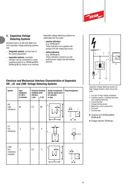
4. Capacitive VoltageDetecting SystemsIEC/EN 61243-5 (E DIN VDE 0682 Part415) classifies voltage detecting systemsinto– integrated systems, as fixed part ofthe system/equipment.– separable systems; a portableindicator can be connected to a fixedcoupling system (e.g. DEHNcap/MDS,DEHNcap/M) by means of an interface.Separable voltage detecting systems aresubdivided into two types– passive indicators(e.g. DEHNcap/P)These indicators are supplied withenergy from the measuring circuit.– active indicators(e.g. DEHNcap/A)These indicators comprise an integratedpower supply and self-testingelement.213 67A54Electrical and Mechanical Interface Characteristics of SeparableHR-, LR- and LRM- Voltage Detecting SystemsSystem Input Electrical threshold Socket arrangement Plug Arrangementimpedance conditions at the and min. space area AX c (MW) interface for indicatorof indicator I (µA) U (V) or plugHRhigh 36 2.5 90resistanceA19454,166Ø 41919KCapacitive Voltage Detecting System forHigh Voltage Systems, Basic Circuit Diagram1 Live part of high voltage installation2 Coupling capacity (coupling electrodewith coupling dielectric)3 Connecting lead4 Voltage-limiting device5 Measuring circuit components6 Test point7 Terminal leadK Coupling Unit DEHNcap/MDS,DEHNcap/MA Voltage Indicator DEHNcap/...LRlow 2 2.5 5resistanceA6,5Ø 6,320LRMlow 2 2.5 5resistance,modifiedA144,1Ø 41966451418