EXPLANATORY INFORMATION - Surgetek
EXPLANATORY INFORMATION - Surgetek
EXPLANATORY INFORMATION - Surgetek

Create successful ePaper yourself
Turn your PDF publications into a flip-book with our unique Google optimized e-Paper software.
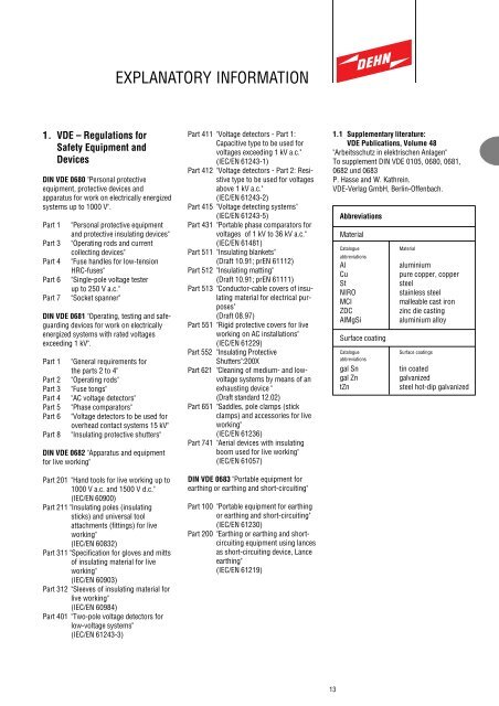
<strong>EXPLANATORY</strong> <strong>INFORMATION</strong>1. VDE – Regulations forSafety Equipment andDevicesDIN VDE 0680 "Personal protectiveequipment, protective devices andapparatus for work on electrically energizedsystems up to 1000 V".Part 1Part 3Part 4Part 6Part 7"Personal protective equipmentand protective insulating devices""Operating rods and currentcollecting devices""Fuse handles for low-tensionHRC-fuses""Single-pole voltage testerup to 250 V a.c.""Socket spanner"DIN VDE 0681 "Operating, testing and safeguardingdevices for work on electricallyenergized systems with rated voltagesexceeding 1 kV".Part 1Part 2Part 3Part 4Part 5Part 6Part 8"General requirements forthe parts 2 to 4""Operating rods""Fuse tongs""AC voltage detectors""Phase comparators""Voltage detectors to be used foroverhead contact systems 15 kV""Insulating protective shutters"DIN VDE 0682 "Apparatus and equipmentfor live working"Part 201 "Hand tools for live working up to1000 V a.c. and 1500 V d.c."(IEC/EN 60900)Part 211 "Insulating poles (insulatingsticks) and universal toolattachments (fittings) for liveworking"(IEC/EN 60832)Part 311 "Specification for gloves and mittsof insulating material for liveworking"(IEC/EN 60903)Part 312 "Sleeves of insulating material forlive working"(IEC/EN 60984)Part 401 "Two-pole voltage detectors forlow-voltage systems"(IEC/EN 61243-3)Part 411 "Voltage detectors - Part 1:Capacitive type to be used forvoltages exceeding 1 kV a.c."(IEC/EN 61243-1)Part 412 "Voltage detectors - Part 2: Resistivetype to be used for voltagesabove 1 kV a.c."(IEC/EN 61243-2)Part 415 "Voltage detecting systems"(IEC/EN 61243-5)Part 431 "Portable phase comparators forvoltages of 1 kV to 36 kV a.c."(IEC/EN 61481)Part 511 "Insulating blankets"(Draft 10.91; prEN 61112)Part 512 "Insulating matting"(Draft 10.91; prEN 61111)Part 513 "Conductor-cable covers of insulatingmaterial for electrical purposes"(Draft 08.97)Part 551 "Rigid protective covers for liveworking on AC installations"(IEC/EN 61229)Part 552 "Insulating ProtectiveShutters":200XPart 621 "Cleaning of medium- and lowvoltagesystems by means of anexhausting device "(Draft standard 12.02)Part 651 "Saddles, pole clamps (stickclamps) and accessories for liveworking"(IEC/EN 61236)Part 741 "Aerial devices with insulatingboom used for live working"(IEC/EN 61057)DIN VDE 0683 "Portable equipment forearthing or earthing and short-circuiting"Part 100 "Portable equipment for earthingor earthing and short-circuiting"(IEC/EN 61230)Part 200 "Earthing or earthing and shortcircuitingequipment using lancesas short-circuiting device, Lanceearthing"(IEC/EN 61219)1.1 Supplementary literature:VDE Publications, Volume 48"Arbeitsschutz in elektrischen Anlagen"To supplement DIN VDE 0105, 0680, 0681,0682 und 0683P. Hasse and W. Kathrein.VDE-Verlag GmbH, Berlin-Offenbach.AbbreviationsMaterialCatalogueabbreviationsAlCuStNIROMCIZDCAlMgSiSurface coatingCatalogueabbreviationsgal Sngal ZntZnMaterialaluminiumpure copper, coppersteelstainless steelmalleable cast ironzinc die castingaluminium alloySurface coatingstin coatedgalvanizedsteel hot-dip galvanized13
2. Operating Rods:Switching Rods, FuseTongs, Voltage Detectorsand Phase ComparatorsDIN VDE 0681/0682 define anoperating rod as an equipment formanually operating, testing, and guardinglive appliances. It consists of one or moreinsulating rods rated at the nominalvoltage and the appropriate operatinghead for the application in question.Examples of operating rods are switchingrods, voltage detectors and phasecomparators for the range above 1 kV.They are marked or on the equipmentlabel.Design of operating rodsAn operating rod consists of a handle, aninsulating element and an operating head.An operating head is that part of theoperating rod containing the contactelectrode, e.g. the head of a switching rodor the indicator of a voltage detector orphase comparator.An insulating element is that section ofthe operating rod between handguard andred ring. It provides an adequate safetydistance and a safe insulation for the user.A contact electrode extension is that partof the operating rod between theinsulating element and the contactelectrode of an operating head. It permitsaccess to distant parts of the system,allows the operating head to be movedpast live parts and elimininates the effectsof interference fields on voltage detectors.The handguard is a distinctive physicalguard separating the handle for theresistive or insulating element. Itspurpose is to prevent the hand fromslipping and passing into contact with theresistive or insulating element.The red ring marks the end of theinsulating element in the direction of theoperating head. It provides the user with avisible limit of contact with live parts ofthe system.The insulating element between red ringand hand guard must not come intocontact with live parts, but may rest ongrounded parts.The test electrode of a voltage detector isthe part of the indicator which contactsthe section of the installation to be tested.It its the operating element of the voltagedetector.Switching Rod12345l Gl Vl H l ll O6Fuse Tongs Voltage Detector712345l H l l l Ol Gl V566Phase Comparator2134l H l l l Ol G7l Vl OMinimum Lengths of Insulating Elements for1) operating rods according to DIN VDE 06812) voltage detectors according to IEC/EN 61243-1 (DIN VDE 0682 Part 411)3) phase comparator according to IEC/EN 61481 (DIN VDE 0682 Part 431)Nominal Voltage Rated Minimum Length of Insulating ElementU N (kV) Voltage L I min (mm)U r (kV) 1) 2) 3)up to 10 12 500 525 52520 24 500 525 52530 36 525 525 52545 52 720 900 —60 72.5 900 900 —110 123 1300 1300 —150 170 1750 1750 —220 245 2400 2400 —380 420 3200 3200 —142134561 Operating head2 Red ring3 Insulating element of length I I4 Handguard5 Handle of length I H6 End piece7 Test electrodel H l ll GI V Length of contact electrode extensionI O Length of upper sectionI G Total length of operating rod
There are basically two types of operating rods:Type A:Not for use in wet weather !Can be used in indoor and outdoor systems, but not in wet weather.PHV Phase ComparatorSwitching RodFuse TongsType B:Also for use in wet weatherCan be used in indoor and outdoor systems under all weather conditions (even whereoperating rods may become damp).PHE III Voltage DetectorPHE III Test HeadPHE Voltage DetectorDC Voltage Detector PHE/GDistance Voltage Detector HSA 194PHV I Phase ComparatorSwitching RodsA further type of operating rod is used for voltage detectors:Type C:Only for use in indoor systems!Can be used in indoor systems at light intensities up to 1000 luxPHG II Voltage Detector15
3. Insulating protectiveshuttersInsulating protective shutters according toDIN VDE 0681 Part 8 and DIN VDE 0682Part 552 are used to provide protectionagainst accidental contact with live parts ofthe installation. They are portable and areinstalled directly by hand or indirectly byusing an insulating rod while parts of theinstallation may be energized.Insulating protective shutters are designedfor short-time use in electrical indoorsystems in accordance with DIN VDE 0101with nominal voltages of 1 kV up to 30 kVac, at nominal frequencies below 100 Hzand nominal voltages of 1.5 kV up to 30kV dc to provide protection against directcontact according to EN 50110 Part 1 whenworking close to live parts.Insulating protective shutters are no lockingfacilities to secure the installation againstreconnection.The protected area is the space restrictingaccess to the danger zone by the insulatingprotective shutter. The minimum distancesshown in the table below for shutter andshutter edges to live parts must beobserved.The protective section (with the length l sand, if necessary, height h s ) of insulatingprotective shutters is that part providingprotection against accidental contact of liveparts. It integrates either a handle or acoupling for being attached to an insulatingor operating rod.Outside of the danger zone, distancesbetween shutter edge and cubicle frame aresubject to the following:– up to 10 mm without barrier– up to 40 mm with at least 100 mm distancefrom shutter edge to danger zone(i.e. "a" + 100 mm)– up to 100 mm near the switchbaseNote:Rated Minimum distancesvoltage of live partsU r(kV) to shutter to shutteredgea (mm) b (mm)3.6 60 07.2 90 012.0 120 2024.0 220 6036.0 320 100a = Minimum distance of live parts to shutter edgeb = Minimum distance of live parts to shutterl C = Protected area (min. 525 mm)Danger zone when applying an insulating protective shutter Type A116
Types:Due to the variety of existing switchgear types, DIN VDE 0681 Part 8 and DIN VDE 0682 Part 552 define four basic types of shuttersAll types include the protected area and the protective section# ! " $= # # 5== +>=>= 5!D 5$>= ?Shutter Type A1 Operation by handShutter Type A2 Operation by hand 5> 5= =!====$%"!=l O l Il Vl G&#$>=Shutter Type A3 Operation using an insulating rodShutter Type A4 Operation by hand1 Live working area2 Protected area3 Protective section with length l s(and height h s)4 Limit mark or red ring5 Guide mark or handguard6 Handle7 Coupling8 Insulating element of the insulating rodwith a length of l Il G Total length of the insulating rodl O Length of the upper section of theinsulating rodl H Length of the handle of the insulating rodl ILength of the insulating element of theinsulating rodl SLength of the protective sectionl CProtected areaa Minimum distance of live parts to insulatingshutter edgeb Minimum distance of live parts to insulatingshutter17
4. Capacitive VoltageDetecting SystemsIEC/EN 61243-5 (E DIN VDE 0682 Part415) classifies voltage detecting systemsinto– integrated systems, as fixed part ofthe system/equipment.– separable systems; a portableindicator can be connected to a fixedcoupling system (e.g. DEHNcap/MDS,DEHNcap/M) by means of an interface.Separable voltage detecting systems aresubdivided into two types– passive indicators(e.g. DEHNcap/P)These indicators are supplied withenergy from the measuring circuit.– active indicators(e.g. DEHNcap/A)These indicators comprise an integratedpower supply and self-testingelement.213 67A54Electrical and Mechanical Interface Characteristics of SeparableHR-, LR- and LRM- Voltage Detecting SystemsSystem Input Electrical threshold Socket arrangement Plug Arrangementimpedance conditions at the and min. space area AX c (MW) interface for indicatorof indicator I (µA) U (V) or plugHRhigh 36 2.5 90resistanceA19454,166Ø 41919KCapacitive Voltage Detecting System forHigh Voltage Systems, Basic Circuit Diagram1 Live part of high voltage installation2 Coupling capacity (coupling electrodewith coupling dielectric)3 Connecting lead4 Voltage-limiting device5 Measuring circuit components6 Test point7 Terminal leadK Coupling Unit DEHNcap/MDS,DEHNcap/MA Voltage Indicator DEHNcap/...LRlow 2 2.5 5resistanceA6,5Ø 6,320LRMlow 2 2.5 5resistance,modifiedA144,1Ø 41966451418
5. Equipment for Earthing andShort-CircuitingPortable equipment for earthing andshort-circuiting in accordance withDIN VDE 0683 Part 1 is an equipment formanual use which can be moved towardsand connected to the connecting points ofparts of electrical systems for earthingand short-circuiting purposes (see EN50110 Part 1, Subclause 6.2.4) withoutguidance (e.g. slots, bushings, guiderails). This equipment comprises earthingand short-circuiting devices and earthingrods.An earthing and short-circuiting device isa device which allows both earthing andshort-circuiting of electrical conductors.The earthing device is a device forconnecting the earthing system to a shortcircuitingdevice or to the equipment to begrounded. It consists of a connection(marked 1 in Figures a-d) and an earthingcable (marked 4 in Figures a and b).The short-circuiting device is a device forconnecting the phase conductors to beshort-circuited (marked 6 in Figures a-d).It consists of connections (2 in Figures a-d), short-circuiting cables or bars (3 inFigures a-d) and node connections asrequired (marked 5 in Figures a and b).Note:In the event of a short-circuit, the shortcircuitcurrent flows via the shortcircuitingdevices, for which current thedevices are rated. This is not the case forearthing devices: these do not carry theshort-circuit current and can therefore berated lower (e.g. smaller cross-section ofearthing cables).This reduction of the earthing cablecross-section is not permissible indevices for use in systems with "solidneutral earthing".A short-circuiting bar is a rigid shortcircuitingdevice.Node connections connect the shortcircuitingcables to each other and to theearthing cable or the short-circuiting barto the earthing cable.Connections link the earthing and shortcircuitingcables or bars directly or viaintermediate elements such as cable lugsto the earthing system and the parts of thesystem, where necessary via connectionpoints.Connection points are those points onparts of the system to which the earthingand short-circuiting devices are connected,e.g. cables, bars, fixed ball points,cylindrical bolts, straps.An earthing rod is an insulating rod to beused manually for guiding the connectionsof earthing and short-circuiting devices toparts of power systems for earthing andshort-circuiting purposes. It consists ofan insulating element, black ring, handleand the necessary coupling for the supporof a connecting lead.An insulating element is that part of theearthing rod between black ring and theend of the earthing rod in the direction ofthe connection. It provides the user withthe necessary safety separation andsufficient insulation. The length of theinsulating element I I must be at least500 mm.l G11l ll H714891013Portable equipment for earthing and shortcircuiting1 Connection to earthing system2 Connection to conductor3 Short-circuiting cable4 Earthing cable5 Node connection6 Connection point to earthing system7 Connection point to conductor8 Insulating element of length I l9 Black ring10 Handle of length L H11 Conductor12 Earthing system13 Rod endpiece14 Couplinga6235416237c1Examples of earthing and short-circuitingdevicesa) three-pole with short-circuiting cablesand earthing cableb) three-pole with short-circuiting barand earthing cablec) single-pole with short-circuiting cablesd) single-pole with short-circuiting cablefor earthing a rail trackb6541237d2312325411661 Connection to earthing system2 Connection to conductor3 Earthing and short-circuiting cable orbar4 Earthing cable5 Node connection6 Phase conductor7 Earthing system (earthing bar, rail track)19
The current rating of the short-circuitingcable or bar depends on the material,cross-section (A) and duration of theshort-circuit (T k).The basis for calculations was the worstcase of a remote short circuit (µ = 1) andthe highest dc current element (χ =1.8) with I k " as the maximum initial acshort-circuit current, which is, accordingto DIN VDE 0102, identical to the continuousshort-circuit current I k and the acbreaking current I a :The necessary cable or bar cross-sectionsfor the short-circuiting device can bedetermined from the diagrams and tables(pages 22 and 23) based on the shortcircuitcurrent and its duration in thesystem.I k " = I k = I aI k "kA10050301053142.0 kA33.526.519.514.010.07.04.5A = 150 mm²1209570503525160.01 0.03 0.05 0.1 0.3 0.5 1 3 5 10 sT kInitial cable temperatureFinal cable temperatureAI k"T kA = 5.07 I k " √ T k20° C250° Cfor T k ≥ 0.5 scable cross-section in mm²maximum initial ac short-circuitcurrent in kA in accordance withDIN VDE 0102short-circuit duration in sCurrent rating of copper short-circuiting cables for use in single-phase and three-phase ac systemsI k "kA100503066.2 kA49.635.624.817.511.21053A = 95 mm²705035251610.01 0.03 0.05 0.1 0.3 0.5 1 3 5 10 sT kInitial cable temperature 20° CFinal cable temperature 250° CA = 5.07 I k " √ T k for T k ≥ 0.08 sAI k"T kcable cross-section in mm²maximum short-circuit currentin kAshort-circuit duration in sCurrent rating of copper short-circuiting cables for use in dc systemsI k"kA1005030105366.9 kA49.635.624.817.511.2A = 95 mm²705035251610.01 0.03 0.05 0.1 0.3 0.5 1 3 5 10 sT kCurrent rating of copper short-circuiting cables for use on overhead traction lines of railwaysInitial cable temperatureFinal cable temperatureAI k"T kA = 4.1 I k " √ T k20° C400° Cfor T k ≥ 0.12 scable cross-section in mm²maximum initial ac short-circuitcurrent in kA in accordance withDIN VDE 0102short-circuit duration in s20
Example of Calculation:Given:Load breaking capacity S aShort-circuit duration T kI k"kA400300200100A = 1000 mm²800To be determined: Required cross section A of cable or barA remote short circuit is assumed.S aThree-phase current I k " = I k = I a = ———√ 3 • U N5040302010600500400300200S aSingle-phase ac current I k " = I k = I a = ——U NThe required cross-section of the cable or bar can now be calculated from the aboveequations or taken from the diagrams using I k ".The permissible rated current time of an earthing and short-circuiting device isexpressed by the cross-section shown on the short-circuiting cables or bars.Notes– Earthing and short-circuiting devices are designed for loading only once at thepermissible rated current time!– Short-circuiting cables of multi-pole earthing and short-circuiting devices must havethe same cross sections.– The cable lengths of earthing and short-circuiting devices have to be at least 1.2times the distance between two connection points. Neither should cable lengths beunnecessarily long, since cables deflect strongly in the event of a short circuits.– The following conditions must be observed for earthing and short-circuiting devicesconnected to cables in parallel to achieve certain total cable cross sections:1. identical cable lengths and cross-sections,2. identical connections and connection points,3. devices fitted close to each other with parallel cable routing,4. the permissible rating per cable has to be reduced to 75 % of the rating forcable cross section.Note:Devices may be fully loaded if it is ensured that arthing and short-circuiting devicesconnected in parallel are only loaded once with the short circuit current (no shortinterruption).This applies generally to systems with nominal voltages above 110 kV.Cross section Max. permissible short circuit current I k , shown for aof copper duration ofcablemm² 10 s 5 s 2 s 1 s ≤ 0.5 s16 1 000 1 400 2 200 3 200 4 50025 1 600 2 200 3 500 4 900 7 00035 2 200 3 100 4 900 6 900 10 00050 3 100 4 400 7 000 9 900 14 00070 4 400 6 200 9 800 13 800 19 50095 5 900 8 400 13 200 18 700 26 500120 7 500 10 600 16 700 23 700 33 500150 9 400 13 200 20 900 29 600 42 00021Current Rating of Short-Circuiting Bars ofE-Cu F 20Initial temperatureFinal temperaturefor bars of E-Cu F 20:A = 5.54 I k " √T k50.1 0.2 0.5 1 2 3 5 10 s20° C250° Cfor bars of E-Al Mg Si 0.5 F17:A = 8.79 I k " √T kT kfor T k ≥ 0.2 sfor T k ≥ 0.2 sA bar cross-section in mm²I k" maximum initial ac short circuitcurrent in kA in accordancewith DIN VDE 0102T k short-circuit duration in sI k"kA4003002001005040302010A = 1000 mm²80060050040030020050.1 0.2 0.5 1 2 3 5 10 sT kCurrent Rating of Short-Circuiting Bars ofE-Al Mg Si 0.5 F17
Applications of Voltage Detectors Types PHE, PHG II and PHV Phase Comparators inType-Tested Prefabricated SwitchgearsThe suitability of our voltage detectors types PHE (also valid for PHE III), PHG II and PHV phase comparators for the use in prefabricatedswitchgears (e.g. in accordance with DIN VDE 0101 Subclause 3.2 and DIN VDE 0670 Part 6) has been proved in tests carried out in cooperationwith the switchgear manufacturers. The corresponding test report is available upon request.Switchgear Manufacturer Type Nominal Voltages U N Suitable Voltage DetectorsABB BA-/BB systems, BAX systems, 10 ... 30 kV PHE, PHG II and PHVBD systemsBC systemsPHE (N versions) and PHG IIAEG GS10, GSD10, GSH10 10 ... 30 kV PHE, PHG II and PHVBELUK BRS 20 kV PHV with test probe, Part No. 759 122Calor-Emag ZE3/4, ZE7/8, ZK4/5, ZK8 L7.6, ZS 1 10 ... 30 kV PHE, PHG II and PHVZW1PHE (N versions)Isopond 10 kV PHE with test prod, Part. No. 766 916Concordia PN 304, PN 306 10 ... 20 kV PHE, PHG II and PHVSprecher + SchuhDriescher Mipak, Minor, Minex, RKL, ZLDT, 10 ... 20 kV PHE, PHG II and PHVTSL, TSLG, FT600, FT750, FL, or PHE test probe, Part No. 766 916FK600, FK750, SK400, BS600, or PHV probes, Part No. 759 111HS24, LDTCfor Type MipakW600, W750, F600, KS400/475 10 ... 30 kV PHE, PHG II and PHVD600 (VBEW switching cell), BS600,or PHV probes, Part No. 759 122 for Type D600D1200, A, B, C, EEimers EKS 10 N, ES 20 N, ES 10 N, EMS 12.190 10 ... 20 kV PHE, PHG II and PHVF & G HGKN, EA, MA, KE, EF, WA, K-HGK 10 ... 20 kV PHE, PHG II and PHVHolec-Hazemeyer Magnefix, MD4, MF und MY 10 kV PHE with test probe, Part No. 766 919Pfisterer MAG 10 kV PHE with test probe P2/10Klöpper KMG 10 ... 20 kV PHE, PHG II and PHVKrone KH10, KHS10d, KHS10dp, 10 ... 30 kV PHE, PHG II and PHVKHS17I, KHS17II, KHS20, KHS30KES10 PHE with test probe, Part No. 766 916PHV with test probe, Part No. 759 111Miebach AS, HUK, TE, TSE, DSS, ASR 10 ... 20 kV PHE, PHG II and PHVNATUS NES, NESCON, NFwZ 3 ... 20 kV PHE and PHG IIRitter GT1, GT3 6 ... 30 kV PHE, PHG II and PHVSachsenwerk/AEG FK (A,C,E,F), WZK, FRA, WK 6 ... 30 kV PHE, PHG II and PHV(A, B, C, E), WDS, R, WBA, FCSiemens 8 BD, 8 CK 6 ... 30 kV PHE with modified test electrode(8 BD: Part No. 076 153, 8 CK: Part No. 076 339)The circuit breaker must havePHG II and PHV on requesttripped before testing systemscontaining a circuit breaker 8 BK 20, 8 BJ 20, 8 BK 30, 8 AA 10 6 ... 20 kV PHE, PHG II and PHVWickmann DZ switchgear cabinet 20 kV PHE, PHG II and PHVZiegler AZ cells 10 ... 20 kV PHE, PHG II and PHV22