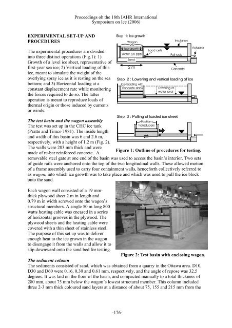
Proceedings oh the 18th IAHR Internati<strong>on</strong>alSymposium <strong>on</strong> Ice (2006)EXPERIMENTAL SET-UP ANDPROCEDURESThe experimental procedures are dividedinto three distinct operati<strong>on</strong>s (Fig.1): 1)Growth of a level <str<strong>on</strong>g>ice</str<strong>on</strong>g> sheet, representative offirst-year sea <str<strong>on</strong>g>ice</str<strong>on</strong>g>; 2) Vertical loading of this<str<strong>on</strong>g>ice</str<strong>on</strong>g>, meant to simulate the weight of theoverlying spray <str<strong>on</strong>g>ice</str<strong>on</strong>g> as it is resting <strong>on</strong> the seabottom; and 3) Horiz<strong>on</strong>tal loading at ac<strong>on</strong>stant displacement rate while m<strong>on</strong>itoringthe forces required to do so. The latteroperati<strong>on</strong> is meant to reproduce loads ofthermal origin or those induced by currentsor winds.Step 1: Ice growthWag<strong>on</strong>Ice growthWater (20 ppt)Step 3 : Pulling of loaded <str<strong>on</strong>g>ice</str<strong>on</strong>g> sheetThe test basin and the wag<strong>on</strong> assemblyPositi<strong>on</strong>The test was set up in the CHC <str<strong>on</strong>g>ice</str<strong>on</strong>g> tanktransducers(Pratte and Timco 1981). The inside lengthand width of this basin was 6 and 2.6 m,respectively, with a height of 1.2 m (Fig. 2).The walls were 203 mm thick and wereFigure 1: Outline of procedures for testing.made of re-bar reinforced c<strong>on</strong>crete. Aremovable steel gate at <strong>on</strong>e end of the basin was used to access the basin’s interior. Two setsof guide rails were anchored <strong>on</strong>to the top of the two l<strong>on</strong>gitudinal walls. These allowed moti<strong>on</strong>of a frame assembly used to carry four c<strong>on</strong>tainment walls, henceforth collectively referred toas wag<strong>on</strong>, into which <str<strong>on</strong>g>ice</str<strong>on</strong>g> growth was to take place and which was used to pull the <str<strong>on</strong>g>ice</str<strong>on</strong>g> block<strong>on</strong>to the <strong>sand</strong>.Sand2 mLoad cellsInsulati<strong>on</strong>Pull rodsStep 2 : Lowering and vertical loading of <str<strong>on</strong>g>ice</str<strong>on</strong>g>Ice loading withc<strong>on</strong>crete slabsLowering ofwater levelC<strong>on</strong>creteActuatorEach wag<strong>on</strong> wall c<strong>on</strong>sisted of a 19 mm-structural members. A single 50 m l<strong>on</strong>g 800thick plywood sheet 2 m in length and0.79 m in width screwed <strong>on</strong>to the wag<strong>on</strong>’swatts heating cable was encased in a seriesof horiz<strong>on</strong>tal grooves in the plywood. Theplywood sheets and the heating cable werecovered with a thin sheet of stainless steel.The purpose of this set up was to deliverenough heat to the <str<strong>on</strong>g>ice</str<strong>on</strong>g> grown in the wag<strong>on</strong>to disengage it from the walls and allow it toslip downward <strong>on</strong>to the <strong>sand</strong> bed for testing.Figure 2: Test basin with enclosing wag<strong>on</strong>.The sediment columnThe sediments c<strong>on</strong>sisted of <strong>sand</strong>, which was obtained from a quarry in the Ottawa area. D10,D30 and D60 were 0.16, 0.30 and 0.61 mm, respectively, and the angle of repose was 32.5degrees. It was laid <strong>on</strong> the floor of the basin, and compacted manually to a total thickness of280 mm, about 75 mm below the wag<strong>on</strong>’s lowest structural member. This column includedthree 2-3 mm thick coloured <strong>sand</strong> layers at a distance of about 75, 155 and 215 mm from the-176-
Proceedings oh the 18th IAHR Internati<strong>on</strong>alSymposium <strong>on</strong> Ice (2006)floor of the basin. These layers were used as markers, to help find out how much of theshearing occurred within the <strong>sand</strong> column as opposed to at the <str<strong>on</strong>g>ice</str<strong>on</strong>g> <strong>sand</strong> interface itself.Instrumentati<strong>on</strong>Two 45 kN capacity water-proofed load cell assemblies were mounted in parallel <strong>on</strong>to thedownstream wag<strong>on</strong> wall (Fig. 1). They were located at the bottom of the wag<strong>on</strong> (as close aspossible to the <str<strong>on</strong>g>ice</str<strong>on</strong>g>-<strong>sand</strong> interface) in order to minimize the amount of torque exerted <strong>on</strong>to therail at the wag<strong>on</strong>’s suspensi<strong>on</strong> points. These cells m<strong>on</strong>itored the load exerted <strong>on</strong>to the wag<strong>on</strong>by a steel bar c<strong>on</strong>nected to two stainless steel pull rods, which extended to and went through<strong>on</strong>e of the basin’s end walls. Sealed guide tubes in the wall ensured water tightness. On theother side of that wall, the rods were clamped <strong>on</strong>to a sec<strong>on</strong>d bar, itself driven by a worm gearactuator. Two gear ratios were available: 20:1 and 60:1. The actuator’s maximum traveldistance was 124 mm, which was recorded by a positi<strong>on</strong> transducer. Positi<strong>on</strong> transducers werealso used to m<strong>on</strong>itor the vertical moti<strong>on</strong> of the <str<strong>on</strong>g>ice</str<strong>on</strong>g> at midpoint al<strong>on</strong>g the four edges of the topc<strong>on</strong>crete slab (Fig. 1). The voltage output from these seven channels (two load cells and fivepositi<strong>on</strong> transducers) was acquired at a rate of 100 Hz with a 30 Hz low-pass filter.ProceduresA 20 ‰ saline soluti<strong>on</strong> was prepared in a <strong>large</strong> pit inside the CHC <str<strong>on</strong>g>ice</str<strong>on</strong>g> tank by diluting sodiumchloride into tap water. Once the <strong>sand</strong> was laid out in the basin, enough of that water wastransferred over to reach the wag<strong>on</strong>’s top rim (Step 1 in Fig. 1). The entire water surfaceoutside the wag<strong>on</strong> was then covered with insulati<strong>on</strong> and the cold room temperature wasbrought down to -15C. An air deflector was set up to orient the flow of cold air from therefrigerati<strong>on</strong> vents <strong>on</strong>to the <str<strong>on</strong>g>ice</str<strong>on</strong>g> surface. An average thickness of 260 mm was achieved withinseveral days, with a growth rate up to 6 mm per hour.The heating cable inside the wag<strong>on</strong> walls was then activated while enough water wasremoved from the test basin so as to allow the <str<strong>on</strong>g>ice</str<strong>on</strong>g> block inside the wag<strong>on</strong> to drop <strong>on</strong>to theunderlying <strong>sand</strong> bed (Step 2 in Fig. 1). It was found that, during this process, a significantamount of melting occurred al<strong>on</strong>g the four bottom edges of the <str<strong>on</strong>g>ice</str<strong>on</strong>g> block, such that these wererounded. This was not objecti<strong>on</strong>able, however, since it reduced ‘edge effects’. In additi<strong>on</strong>,before every test, the leading edge was probed manually and any sediment accumulati<strong>on</strong> infr<strong>on</strong>t of the <str<strong>on</strong>g>ice</str<strong>on</strong>g> block was removed. Half way through the test program, the <str<strong>on</strong>g>ice</str<strong>on</strong>g> became toothin for testing to proceed so a sec<strong>on</strong>d growth stage (up to 370 mm) was d<strong>on</strong>e. Such thinningeither resulted from partial melting (the floor of the CHC <str<strong>on</strong>g>ice</str<strong>on</strong>g> tank is not insulated) orabrasi<strong>on</strong>.The surface of the <str<strong>on</strong>g>ice</str<strong>on</strong>g> block was then covered with a 3 mm thick rubber foam and a 40 mmthick plywood board. These formed a base <strong>on</strong>to which a 470 kg c<strong>on</strong>crete slab was laid. Oncethe four positi<strong>on</strong> transducers were installed <strong>on</strong> top of the slab, horiz<strong>on</strong>tal loading couldproceed (Step 3 in Fig. 1). After test completi<strong>on</strong>, the actuator was brought back to its initialpositi<strong>on</strong> and another c<strong>on</strong>crete slab was added to the vertical load for the next 124-mm test,and so <strong>on</strong>, up to a total mass of six t<strong>on</strong>s. This corresp<strong>on</strong>ded to an upper bound stress <strong>on</strong> theseabed of about 15 kPa (taking into account all test parameters, as noted below).TESTINGA total of 48 <strong>tests</strong> were c<strong>on</strong>ducted, divided into four series, each of which with increasingvertical load and at a given displacement rate. Another series was d<strong>on</strong>e with a c<strong>on</strong>stant load-177-