13668: Edge® 9M 2 or 4 Strobe Lighthead Kit - Whelen Engineering
13668: Edge® 9M 2 or 4 Strobe Lighthead Kit - Whelen Engineering
13668: Edge® 9M 2 or 4 Strobe Lighthead Kit - Whelen Engineering

You also want an ePaper? Increase the reach of your titles
YUMPU automatically turns print PDFs into web optimized ePapers that Google loves.
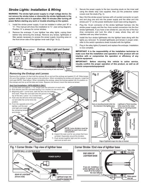
<strong>Strobe</strong> Lights: Installation & WiringWARNING: The strobe light power supply is a high voltage device. Donot remove the strobe tubes <strong>or</strong> dismantle the strobe lightheads in thesystem while the unit is in operation. Wait 10 minutes after turning offpower Bef<strong>or</strong>e starting any w<strong>or</strong>k <strong>or</strong> trouble shooting on the system.1. Install the strobe power supply. It can be installed in either p<strong>or</strong>t “B” <strong>or</strong>“C”. This manual will show the installation to “C”. (see wiring diagram).Position “A” is always f<strong>or</strong> c<strong>or</strong>ner strobes.2. Remove the endcaps. If your lightbar has alley lights, unplug thembef<strong>or</strong>e fully removing the endcap. Remove any lenses, lightheads <strong>or</strong>filler panels necessary to access the power supply mounting area onthe front driver side of the lightbar inner wall (Figs 1 & 2).Removing the Endcap and LensesRemove the 4 screws (A) that hold the endcap (B) on and pull the endcap and gasket (C) off. Slide lenses(D) out of the lightbar, to gain access to the extrusion. When reinstalling the lenses and spacers, install thec<strong>or</strong>d seal (NFPA / See below). When reinstalling the endcap, place the endcap gasket into it's position onthe endcap and line up all the tabs and holes. Spacers (not shown) mount the same as lenses.Seal C<strong>or</strong>d Installation / NFPA MODELS ONLY:1-Cut the seal c<strong>or</strong>d approx. 1-1/2" longer than the extrusion on each side.2-Rub silicone over the c<strong>or</strong>d seal leaving 3 to 4 inches on one end dry.3-Beginning with 1 c<strong>or</strong>ner lens, start the lens into the bottom3-lens track. Place the c<strong>or</strong>d seal onto the groove in the3-top of the lens. Leave 1 to 2 inches free. D4-Hold onto the left end of the seal hanging4-out and slide the c<strong>or</strong>ner lens into4-position.5-From the opposite end of the5-lightbar, pull the seal5-c<strong>or</strong>d tight and install5-the remaining lenses5-and divider.A1 Align<strong>Lighthead</strong>with the 4bosses inthe endcapB2 Snap <strong>Lighthead</strong>into 4 barbs inendcapEndcap, Alley Light and GasketPlace endcap gasket onto endcap locating all tabs and holesCGasket<strong>Lighthead</strong>Insert c<strong>or</strong>d seal into track in lensNOTE: Lens dividers must beinstalled as each lens is putinto position6-Inspect the seal c<strong>or</strong>d f<strong>or</strong> any areas that have6-wrinkled. Especially around the dividers.7-Push lenses together tight and trim excess7-seal c<strong>or</strong>d at each end.3. Secure the power supply to the two mounting studs on the inner wallusing the elastic stop nuts supplied, then put the protective rubbercovers over the studs (Fig. 3).4. Nex,t find the strobe power harness with a 6-socket connect<strong>or</strong> on eachend and plug one end into the power supply and the other end intostrobe p<strong>or</strong>t “C” on the power distribution board (see wiring diagram).5. Plug the 12-pin connect<strong>or</strong> of the strobe lighthead harness into thestrobe power supply and the four Amp socket connect<strong>or</strong>s into the fourstrobe lightheads. If you have a two strobe kit, use only two of the fourAmp connect<strong>or</strong>s and tuck the other 2 away where they will notinterfere with any other functions.6. Install the four strobe lightheads into the lightbar base along with thelights you removed. To reinstall lightheads and lenses in proper <strong>or</strong>der,refer to the switch operations sheet included with the lightbar.7. Plug in the alley lights (if present) and replace the endcaps. Installationis now complete.IMPORTANT: It is the responsibility of the installation technician tomake sure that the installation and operation of this product will notinterfere with <strong>or</strong> compromise the operation <strong>or</strong> efficiency of anyvehicle equipment.IMPORTANT! Bef<strong>or</strong>e returning this vehicle to active service,visually confirm the proper operation of this product, as well as allvehicle components/equipment!DFig. 2Ears on mounting bracket slide intothe channels in the lightbar base.CORNERSTROBE<strong>Lighthead</strong> <strong>or</strong> Panel mountingholes snap into the raisedbosses on mounting bracket.Edge of lighthead snaps into clips on bracket.LIGHTHEAD<strong>or</strong>FILLER PANELFig. 1 C<strong>or</strong>ner <strong>Strobe</strong> / Top view of lightbar baseCENTER WALL of LIGHTBAR BASEPOWER SUPPLYC<strong>or</strong>ner <strong>Strobe</strong> / End view of lightbar baseEND VIEW OFLIGHTBAR BASETabs slideinto baseCORNER STROBETABREAR OF LIGHTBAR(Drivers Side)<strong>Lighthead</strong> snaps intomounting bracket here.Page 2If you are installing a newstrobe lighthead, snap thisbead off of the bottom ofthe new reflect<strong>or</strong>Slide spacerinto bar