Signal Processing and Coding for TDMR Channels 1 Front ... - IDEMA
Signal Processing and Coding for TDMR Channels 1 Front ... - IDEMA
Signal Processing and Coding for TDMR Channels 1 Front ... - IDEMA
- No tags were found...

You also want an ePaper? Increase the reach of your titles
YUMPU automatically turns print PDFs into web optimized ePapers that Google loves.
1 <strong>Front</strong> matter1.a.DateApril 29, 20111.b.Abstract<strong>Signal</strong> <strong>Processing</strong> <strong>and</strong> <strong>Coding</strong> <strong>for</strong> <strong>TDMR</strong> <strong>Channels</strong>Industry is approaching the limit of the data storage density possible by reading <strong>and</strong> writing single tracks onconventional magnetic disks. The proposed project considers an alternate approach called two dimensionalmagnetic recording (<strong>TDMR</strong>), wherein bits are read <strong>and</strong> written in two dimensions on conventional magneticdisks. These disks have magnetic grains of different sizes packed r<strong>and</strong>omly onto the disk surface. A keyproblem in <strong>TDMR</strong> is that a given magnetic grain retains the polarization of the last bit written on it; hence,if a grain is large enough to contain two bit centers, the older bit will be overwritten by the newer one. Bitsare read from the disk by a 2D read head. Because bits are stored at such high density, the signal read froma given bit will suffer 2D intersymbol interference (2D ISI) from adjacent bits in both down <strong>and</strong> cross trackdirections. As the result of a recent NSF-funded research project, the Co-PIs have developed iterative 2DISI equalization algorithms that are among the best per<strong>for</strong>ming reported in the open literature. Many of thetechniques developed at WSU <strong>for</strong> the 2D-ISI channel can also be used <strong>for</strong> the <strong>TDMR</strong> detection problem. Toenable <strong>TDMR</strong> to become viable, advanced 2D signal processing <strong>and</strong> coding techniques must be developedto combat the combination of grain overwriting <strong>and</strong> 2D ISI.This proposal’s objective is to investigate signal processing <strong>and</strong> coding techniques <strong>for</strong> <strong>TDMR</strong> channelsthat can approach the recently estimated channel capacity of about 0.5 bit/grain. Specific objectives include:1. Investigate detectors <strong>for</strong> <strong>TDMR</strong> magnetic grain channels based on three channel models of successivelyincreasing complexity: the rectangular-grain, discrete-grain Voronoi, <strong>and</strong> Voronoi models.2. Integrate <strong>TDMR</strong> detection, 2D ISI equalization <strong>and</strong> channel coding in an overall turbo-detection architecture.3. Evaluate our developed algorithms using statistically generated <strong>TDMR</strong> data <strong>and</strong> experimental <strong>TDMR</strong>data from member companies of the ASTC.A version of this proposal has recently been submitted to NSF as a GOALI proposal with industry partnerHitachi; the GOALI requests support <strong>for</strong> two Ph.D. students <strong>for</strong> three years. The requested ASTC fundingwould support one additional Ph.D. student <strong>for</strong> three years. The ASTC student would work on the interface<strong>and</strong> interaction between channel coding, <strong>TDMR</strong> detection, <strong>and</strong> 2D ISI equalization, while the two GOALIstudents would work on <strong>TDMR</strong> detection <strong>and</strong> 2D ISI equalization. The ASTC student would investigateissues such as: (a) interleaver design to spread commonly encountered error patterns out over 2D space tofacilitate error correction; (b) symbol mapping to allow the channel code to easily detect <strong>and</strong> correct highprobability error patterns generated by the 2D ISI equalizer, <strong>and</strong> the interaction between the symbol mapper<strong>and</strong> the channel decoder; (c) introduction of intentional correlation to the channel coded bit stream in orderto improve the per<strong>for</strong>mance of the overall system; <strong>and</strong> (d) channel capacity computation <strong>for</strong> the combinedmagnetic grain <strong>and</strong> 2D ISI channel models.1.c.Proponents <strong>and</strong> affiliationsDr. Benjamin Belzer, Principal Investigator, <strong>and</strong> Dr. Krishnamoorthy Sivakumar, Co-Principal Investigator,Washington State University School of Electrical Engineering <strong>and</strong> Computer Science.1
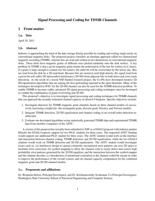
1.d.Designated contact person1. Technical Point of Contact: Dr. Benjamin Belzer, Washington State University School of EECS, P.O.Box 642752, Pullman, WA 99164-2752. Phone: 509-335-4970. Email: belzer@eecs.wsu.edu.2. Contractual Point of Contact: Dan Nordquist, Washington State University Office of Grant <strong>and</strong> ResearchDevelopment, 423 Neill Hall, PO Box 643140, Pullman WA 99164-3140. Phone: 335-7717.Email: nordquist@wsu.edu.2 Subject of research <strong>and</strong> relevance to issues to be solved2.a.Description of the research matter <strong>and</strong> its connection with ASTC stated goalsThe proposed project addresses the ASTC<strong>TDMR</strong> topic number 3: joint 2D practicalsoft detection <strong>and</strong> coding design <strong>for</strong> <strong>TDMR</strong>.Fig. 1 from [1] shows an overview of a proposed<strong>TDMR</strong> system that could potentiallyachieve 10 Terabits/in 2 , which is about 10times the maximum density limit of currentsingle-track magnetic disk storage systems.A st<strong>and</strong>ard magnetic disk has magneticgrains of different sizes packed r<strong>and</strong>omlyonto the disk surface. In the proposed<strong>TDMR</strong> system, in<strong>for</strong>mation bits are channelcoded to a density of two bits per magneticgrain, <strong>and</strong> written by a special shingledwrite process that enables high density Figure 1: Overview of <strong>TDMR</strong> (from [1]; used by permission.)recording. A key problem with this processis that a given magnetic grain retains the polarization of the last bit written on it; hence, if a grain is largeenough to contain two bit centers, the oldest bit will be overwritten by the newer one if they have differentpolarities. Bits are read from the disk by a 2D read head capable of reading multiple bits at a time in bothdown- <strong>and</strong> cross-track directions. Because the bits are stored at such high density, the signal read from agiven bit will suffer interference from adjacent bits in both down <strong>and</strong> cross track directions; this is called2D intersymbol interference (2D ISI). To recover the original data bits, advanced 2D signal processing <strong>and</strong>coding techniques must be developed to combat the combination of grain overwriting <strong>and</strong> 2D ISI.Proposal Objectives: The objective of this proposal is to investigate signal processing <strong>and</strong> codingtechniques <strong>for</strong> <strong>TDMR</strong> channels that can approach the recently estimated channel capacity of about 0.5bit/grain. Specific technical objectives include:2.a.i.1. Investigate detectors <strong>for</strong> <strong>TDMR</strong> magnetic grain channels based on three channel models of successivelyincreasing complexity: the rectangular-grain, discrete-grain Voronoi, <strong>and</strong> Voronoi models.2. Integrate <strong>TDMR</strong> detection, 2D ISI equalization <strong>and</strong> channel coding in an overall turbo-detection architecture.3. Evaluate our developed algorithms using statistically generated <strong>TDMR</strong> data <strong>and</strong> experimental <strong>TDMR</strong>data from member companies of the ASTC.Related work by other groupsPrevious systems-level work in <strong>TDMR</strong> has mainly considered channel modeling <strong>and</strong> channel capacity. Therehas been relatively little work on joint detection <strong>and</strong> decoding algorithms <strong>for</strong> <strong>TDMR</strong>; although there have2
een a number of proposed approaches, very few have been pursued to the point where actual bit error rate(BER) per<strong>for</strong>mance can be quantified. (One exception is the work by Pan <strong>and</strong> Ryan et. al. in [2]; this paperis discussed further in subsection 2.b.i. below.) Even less work has been done on signal processing <strong>and</strong>coding to combat the combined effects of magnetic grain overwrite <strong>and</strong> 2D ISI.Among the simplest <strong>TDMR</strong> models that captures the 2D nature of the <strong>TDMR</strong> channel is the rectangulardiscrete-grain model (DGM). As shown in Fig. 2 (a), the rectangular DGM consists of four distinct graintypes consisting of unions of the smallest grain type; relative to the smallest type their sizes are 1 × 1, 2 × 1,1 × 2 <strong>and</strong> 2 × 2. The four grain types occur with probabilities P 1 ,...,P 4 . Typically it is assumed that thereis one coded bit per 1 × 1 grain. The rectangular DGM model was introduced by Kavcic et. al. in [3],where capacity upper <strong>and</strong> lower bounds <strong>for</strong> this model were derived showing a potential density of 0.6 bitsper grain, translating to 12 Terabits/in 2 at typical media grain densities of 20 Teragrains/in 2 . This paper alsoshowed that the rectangular DGM could easily be generalized into a model that included 2D ISI, <strong>and</strong> couldalso be generalized into a model with rectangular grains but non-integer grain boundaries; non-integer grainboundaries are a simple attempt to model the r<strong>and</strong>om alignment of actual magnetic grains.A more general model called the Voronoi-based discrete-grain model (VDGM) in [4] was introducedin [5]. In the VDGM, shown in Fig. 2 (b), the grains (shown gray-shaded in the figure) are constructedof arbitrary unions of discrete tiles (“tiny squares” in the figure), <strong>and</strong> can there<strong>for</strong>e assume a much widervariety of shapes <strong>and</strong> sizes than the rectangular DGM.A still more general model, shown in Fig. 2 (c), is called the Voronoi model. Here the grain centers areconstructed by adding a (usually fairly small) r<strong>and</strong>om offset to a regular grid [6], <strong>and</strong> the grains are simplythe Voronoi regions about the grain centers. To our knowledge <strong>TDMR</strong> detection <strong>and</strong> coding schemes havenot been developed <strong>for</strong> either the VDGM or Voronoi models to the point where BER per<strong>for</strong>mance can bequantified, although several detection schemes are proposed in [4]. (a)Figure 2: Magnetic grain models considered in this proposal: (a) rectangular discrete grain model; (b)Voronoi discrete grain model; (c) Voronoi model.(b)(c)2.a.ii.The 2D ISI ProblemConsider the detection of an M × N binary equiprobable two dimensional (2D) independent <strong>and</strong> identicallydistributed (i.i.d.) image f with elements f(k, l) ∈ {−1, 1} from received image r with elements (pixels)r(m, n) = h(m − k, n − l) · f(k, l)+w(m, n). (1)k lIn (1), h(k, l) are elements of a finite impulse response 2D mask h, <strong>and</strong> the w(m, n) are zero mean i.i.d.Gaussian r<strong>and</strong>om variables (r.v.s). The model in (1) applies, e.g., to 2D data storage systems, which sufferfrom 2D intersymbol interference (ISI) at high storage densities. Such systems are under active development3
<strong>for</strong> next generation optical disk storage (e.g., [7]), <strong>and</strong> holographic data storage (e.g., [8]) <strong>and</strong> have beenproposed <strong>for</strong> two-dimensional magnetic storage [1].Direct maximum likelihood (ML) detection of f from r requires comparison of r with 2 MN c<strong>and</strong>idateimages, <strong>and</strong> is there<strong>for</strong>e impractical <strong>for</strong> typical image dimensions of M,N ≥ 64. For one dimensionalsignals, the Viterbi algorithm (VA) provides an efficient method <strong>for</strong> ML detection of ISI-corrupted data [9].But the VA does not generalize to two or higher dimensions. Nonetheless, asymptotically tight union boundson the per<strong>for</strong>mance of 2D ML detection have been developed in [10]; these bounds are useful in assessingthe per<strong>for</strong>mance of 2D detection algorithms at high SNR.A number of 2D decision-feedback VAs (DFVAs) have been constructed, based on row-by-row rasterscanning of the image (e.g. [11–14]). To our knowledge, [13, 14] employed the first iterative algorithm<strong>for</strong> 2D ISI reduction; the DFVA was run on rows <strong>and</strong> columns, <strong>and</strong> bits agreeing in both directions werefixed <strong>for</strong> subsequent iterations. Subsequent work employed the turbo principle (after turbo coding [15]). In[16], the 2D convolution is decomposed into two 1D computations, <strong>and</strong> an iterative algorithm exchangessoft in<strong>for</strong>mation between 1D soft-in soft-out (SISO) detectors. In [17], the binary source image is codedwith a low-density parity check (LDPC) error correcting code be<strong>for</strong>e transmission over a separable 2D-ISIchannel. Separability is exploited to construct an iterative row-column algorithm in which a non-binarycolumn SISO detector is followed by a binary row SISO detector, followed by an iteration of the LDPCdecoder, etc. The LDPC’s coding gain enables [17] to approach within less than 1 dB the bit error rate(BER) curve <strong>for</strong> the non-ISI channel. In [18], soft in<strong>for</strong>mation is exchanged between maximum a posteriori(MAP) row <strong>and</strong> column detectors; this scheme avoids decision feedback by making decisions on multiplerows/columns, rather then one row/column at a time. An iterative row-column soft decision feedback (SDF)algorithm (IRCSDFA) similar to that of [18], which outper<strong>for</strong>ms the algorithms of [14], [16], <strong>and</strong> [18] wasalso recently developed [19].Approximations of generalized belief propagation (GBP) are developed <strong>for</strong> the 2D-ISI <strong>and</strong> related problemsin [20]. The GBP-based 2D-ISI equalizer uses exact inference over the sub-region of the image coveredby the ISI mask, <strong>and</strong> passes messages between adjacent sub-regions. The GBP equalizer achieves ML per<strong>for</strong>mance<strong>for</strong> the cases tested in [20], but has been demonstrated only on small (20 × 20 or smaller) images<strong>and</strong> with 2 × 2 ISI masks with relatively low-magnitude coefficients relative to the main tap h(0, 0); suchcases are easily h<strong>and</strong>led because the nearby boundary conditions greatly aid the estimation, <strong>and</strong> because theISI is relatively less compared to masks with a flatter coefficient energy distribution.A brief description of the trellis construction used in the IRCSDFA is presented next (see [19] <strong>for</strong>details).2.a.iii.Trellis definitionTwo-dimensional convolution can be viewed as the inner product of imagef(m, n) with inverted mask h(−k, −l), with mask coefficient h(0, 0) atpixel position (m, n). The inverted mask raster-scans through the imagerow-by-row or column-by-column. For the row-by-row case we define theIRCSDFA trellis states <strong>and</strong> inputs as in Figure 3. Trellis generation <strong>for</strong>the 3 × 3 mask on the mth image row is initiated by placing the inputmarked (m, n) in Figure 3 at the left end of the row, where the initialvalues of the six state pixels are −1 due to the boundary conditions, <strong>and</strong>the vector of three input pixels can take eight different values. The entirestate/input block is then shifted right to pick up the next three input pixels,<strong>and</strong> the previous three input pixels become the middle three state pixels.The trellises <strong>for</strong> each row are terminated at the right end of the row by extrashifts into the boundary pixels. For the 3 × 3 mask, the 64-state trellis haseight branches entering <strong>and</strong> leaving each state, with no parallel branches. Figure 3: Trellis definition.At each position (m, n), the trellis branch output vector consists of three3 × 3 inner products between the inverted mask <strong>and</strong> the pixel values defined by the trellis; the upper inner4
product uses two feedback rows, the middle uses one feedback row, <strong>and</strong> the lower uses received pixels only.The branch metric is the squared Euclidean distance between the branch output <strong>and</strong> the received pixel vector[r(m, n),r(m +1,n),r(m +2,n)]. The column-by-column case is similar to the row-by-row case. As theimage pixels are i.i.d., the above-described trellis constructions impose the Markov condition that, given thecurrent trellis state, subsequent states <strong>and</strong> branch outputs are independent of past states or outputs. ThisMarkov condition allows the use of a modified BCJR [21] algorithm <strong>for</strong> detection.Subsequently, we developed an iterative soft-decision feedback zigzag algorithm (ISDFZA) [22]. Incontrast to the IRCSDFA, which is based on row or column scanning, the ISDFZA employs a zig-zag scanto construct a space-varying trellis spanning the entire image; the longer trellis provides improved per<strong>for</strong>manceat low SNR. The IRCSDF detector was then concatenated with the ISDFZA where soft in<strong>for</strong>mationwas exchanged between the two detectors in an iterative fashion. The concatenated system [22] providesfurther improvement with overall per<strong>for</strong>mance close to the corresponding maximum likelihood (ML) bound.Extensive comparisons in [22] show that the concatenated ISDFZA-IRCSDFA provides superior or competitiveper<strong>for</strong>mance to other recently proposed 2D-ISI equalization algorithms that constituted state-of-the-artat the time of publication of [22]. Specifically, in [22] direct comparisons are made to the previously publishedalgorithms of [16], [17], [20], <strong>and</strong> also to our own previous IRCSDFA of [19] (which had previouslybeen shown to have better per<strong>for</strong>mance than [18]). For this reason our more recent results presented next insubsection 2.a.iv. are compared only to the best results reported in [22], as we believe that [22] establisheda new state-of-the-art <strong>for</strong> equalization of 2 × 2 or 3 × 3 2D ISI channels at the time it was published.2.a.iv.Recent work by the PIsIn traditional iterative row-column soft decision feedback (IRCSDF) algorithms [14, 16, 19] <strong>for</strong> a twodimensionalintersymbol interference channel with additive white Gaussian noise, the pixel estimates usedas extrinsic in<strong>for</strong>mation exchanged between detectors were assumed to be statistically independent. Althoughthis assumption simplifies the overall algorithm, there is no theoretical basis <strong>for</strong> the independenceassumption. Indeed, the dependence between extrinsic in<strong>for</strong>mation estimates of pixels was verified experimentally[23]. Motivated by this, the PIs have redesigned the traditional IRCSDFA [19] by dropping theindependence assumption on the extrinsic in<strong>for</strong>mation exchanged between the row <strong>and</strong> column decoders. Inthe joint version of the IRCSDF, referred to as the block (BLK) algorithm, we estimate <strong>and</strong> exchange jointstatistics <strong>for</strong> the pixels involved in the extrinsic in<strong>for</strong>mation exchange. To address the increased computational<strong>and</strong> storage complexity introduced by the joint statistics, we have also developed a simplified versionof the block (SBLK) algorithm. Experimental results demonstrate that the SBLK algorithm per<strong>for</strong>ms almostas well as the BLK algorithm. In the following, we present a brief description of BLK algorithm; see [23]<strong>for</strong> more details.Block AlgorithmFollowing the notations <strong>and</strong> derivation of the IRCSDFA (assuming independence of pixels in extrinsicin<strong>for</strong>mation) from [19], [22], we present only the most relevant equations from [19], which get modified inthe BLK algorithm. Figure 4 parts (a) (2 × 2 mask) <strong>and</strong> (g) (3 × 3 mask) show the state (labeled s), input(labeled i), <strong>and</strong> feedback (labeled ω) pixels <strong>for</strong> the row decoder; parts (d) <strong>and</strong> (j) show similar in<strong>for</strong>mation<strong>for</strong> the column decoder. The main modification is in the computation of γ in the traditional BCJR algorithm[21]. Computation of γ in the traditional BCJR algorithm [19] (see equations (2), <strong>and</strong> (3) below) requiresa priori probability of the input block (two pixels <strong>for</strong> 2 × 2 mask <strong>and</strong> three pixels <strong>for</strong> 3 × 3 mask) <strong>and</strong> apriori probability of the feedback block (two pixels <strong>for</strong> 2 × 2 mask <strong>and</strong> six pixels <strong>for</strong> 3 × 3 mask), from theextrinsic in<strong>for</strong>mation obtained from the previous decoder in the overall iterative scheme. In the sequel, wepresent these equations <strong>for</strong> the 3 × 3 mask; obvious changes lead to expressions <strong>for</strong> the 2 × 2 case.γ i (y k ,s ,s)=p (y k | U = i,S k = s, S k−1 = s ) × P (U = i | s, s ) × P (s | s ), (2)5
wherep (y k | U = i,S k = s, S k−1 = s )=P (y k2 | i 0 ,i 1 ,i 2 ,s,s ) × Ω 2P (Ω 2 )P (y k1 | i 0 ,i 1 ,s,s , Ω 2 )× P (Ω 1 )P (y k0 | i 0 ,s,s , Ω 1 , Ω 2 ) .Ω 1(3)Here k represents the trellis stage, y k =(y k0 ,y k1 ,y k2 ) is the received vector, i =(i 0 ,i 1 ,i 2 ) is the inputvector, s, s are the current <strong>and</strong> previous states, <strong>and</strong> Ω 1 , Ω 2 represents the two rows of feedback pixels. In[19], [22], <strong>for</strong> simplicity, we assumed that the pixels in the input/feedback block were statistically independent.Consequently, marginal probabilities (from the extrinsic in<strong>for</strong>mation) were multiplied to obtain therequired joint probabilities. In other words, we set (<strong>for</strong> input pixel block):<strong>and</strong> <strong>for</strong> feedback pixel block:P (s | s )=P (U = i) =P (i 0 ) × P (i 1 ) × P (i 2 ) (4)P (Ω 1 )=P (ω 0 ) × P (ω 1 ) × P (ω 2 ) <strong>and</strong> P (Ω 2 )=P (ω 3 ) × P (ω 4 ) × P (ω 5 ). (5)The independence assumption in (4) <strong>and</strong> (5) is strictly speaking not valid in practice; this was verifiedbased on the joint probabilities obtained in our block algorithm. The key idea is to replace equations (3)–(5)with equations (6)–(7) shown below, respectively. p (y k | U = i,S k = s, S k−1 = s )=P (y k2 | i 0 ,i 1 ,i 2 ,s,s ) × P (Ω 1 , Ω 2 )Ω 1 ,Ω 2 (6)P (y k1 | i 0 ,i 1 ,s,s , Ω 2 )P (y k0 | i 0 ,s,s , Ω 1 , Ω 2 ) ,P (s | s )=P (U = i) =P (i 0 ,i 1 ,i 2 ), <strong>and</strong> P (Ω 1 , Ω 2 )=P (ω 0 ,ω 1 ,ω 2 ,ω 3 ,ω 4 ,ω 5 ). (7)We now address the problem of obtaining the joint probabilities in equation (7). In the BCJR algorithmwe compute α k (s) =P (S k = s, y1 k), β k(s) =P (y Nrk+1 | S k = s) <strong>and</strong> γ i (y k ,s,s )=P (U = i,S k =s, y k | S k−1 = s ) by a <strong>for</strong>ward-backward procedure, where N r denotes the number of stages in thetrellis. We then compute λ i k (s) =P (U = i,S k = s, y N r1 )= s α k−1(s )β k (s)γ i (y k ,s,s ), which givesthe unnormalized probability P (U = i). To estimate the pixel located at (m, n) from the vector λs, wemarginalize the λs over the other two input pixels i 1 <strong>and</strong> i 2 :λ i 0k(s) = λ i k (s). (8)i 1 ,i 2The corresponding log likelihood ratio (LLR) is given by (in the binary case, there is one LLR per pixel, the“other LLR” being 0):sL(k) = logλi0=+1 k(s). (9)(s)s λi0=−1 kIn our block (BLK) algorithm, we compute the joint probability of the block of pixels that constitute thestate <strong>and</strong> input (block of four pixels <strong>for</strong> 2 × 2 mask <strong>and</strong> block of nine pixels <strong>for</strong> 3 × 3 mask) as shown inFigure 4 (a) <strong>and</strong> (g). We first compute the same α, β; γ is computed based on (2), (6)–(7). For computingthe 16- or 512-valued LLRs L k (i,s), we do not sum the λ i k (s) probabilities over the inputs i 1, i 2 <strong>and</strong> thestate s as in (8) <strong>and</strong> (9). Instead of computing two LLRs (one of them being equal to zero) <strong>for</strong> each pixel,<strong>for</strong> each pixel we now have 2 4 = 16 LLRs <strong>for</strong> the 2 × 2 mask, <strong>and</strong> 2 9 = 512 LLRs <strong>for</strong> the 3 × 3 mask asfollows:L k (i,s) = logλ i k (s)λ i=i 0k(s = s 0 )6. (10)
In (10), <strong>for</strong> the 2 × 2 mask i = (i 0 ,i 1 ), i 0 =(−1, −1), s = (s 0 ,s 1 ), <strong>and</strong> s 0 = (−1, −1).For the 3 × 3 case, i = (i 0 ,i 1 ,i 2 ), i 0 =(−1, −1, −1), s = (s 0 ,s 1 ,s 2 ,s 3 ,s 4 ,s 5 ), <strong>and</strong>s 0 =(−1, −1, −1, −1, −1, −1).Be<strong>for</strong>e passing this in<strong>for</strong>mation to the nextdecoder (in an iterative scheme), the input extrinsicLLR is subtracted from the LLR computed in(10). It is customary to also multiply the extrinsicLLR by a weight factor less than one, since theextrinsic in<strong>for</strong>mation is not reliable, at least in theinitial iterations. Designing an optimal weightschedule (as a function of iteration number) hasbeen discussed in [22], under the independenceassumption. Finally, note that, the joint probabilityof the four/nine-pixel block can be suitablymarginalized to obtain the joint input probability<strong>and</strong> joint feedback probability required in equations(7). This marginalization is shown in Figure4 (b, e) <strong>and</strong> (h, k).Simplified Block AlgorithmThe BLK algorithm requires the exchange of16-valued (512-valued) LLR <strong>for</strong> each pixel <strong>for</strong>the 2 × 2 (3 × 3) mask. This involves significantlymore storage <strong>and</strong> computation comparedto our original IRCSDFA, where there was a singleLLR <strong>for</strong> each pixel. A simplified version ofthe block algorithm, which we call the SBLK algorithm,has been developed [23] to address thisproblem.The key idea is to store <strong>and</strong> exchange LLRsonly <strong>for</strong> the joint pairs that we need in the nextdecoder. This is illustrated in Figure 4 parts (c,f) <strong>and</strong> (i, l). For the 2 × 2 mask, we only needto store two pixel pairs which is 2 2 × 2 = 8LLRs — half the 16 LLRs required in the BLKalgorithm. For the 3 × 3 mask, we only need2 6 +2 3 = 72 LLRs — almost one seventh of the512 LLRs required in the BLK algorithm. Sincewe do not need subtraction of the input LLR, theper<strong>for</strong>mance of the simplified algorithm is almostas good as that of the block algorithm. Figure 4: Structure definition of the BLK <strong>and</strong> SBLK algorithm<strong>for</strong> 2 × 2 mask ((a) through (f)) <strong>and</strong> 3 × 3 mask((g) through (l)): (a), (g) state <strong>and</strong> input pixels definitionof row decoder; (b), (h) joint block from the rowdecoder <strong>and</strong> the marginalization applied in the columndecoder <strong>for</strong> the BLK algorithm; (c), (i) joint blocks fromthe row decoder <strong>and</strong> their roles in the column decoder <strong>for</strong>the SBLK algorithm; (d), (j) state <strong>and</strong> input pixels definitionof column decoder; (e), (k) joint block from thecolumn decoder <strong>and</strong> the marginalization applied in therow decoder <strong>for</strong> the BLK algorithm; (f), (l) joint blocksfrom the column decoder <strong>and</strong> their roles in the row decoder<strong>for</strong> the SBLK algorithm. (In (b), (e), (h), <strong>and</strong> (k),‘X’ indicates the pixels which are marginalized out.)Soft-Decision Feedback Zigzag Algorithm with Joint Extrinsic In<strong>for</strong>mation ExchangeThe idea of estimating <strong>and</strong> exchanging joint extrinsic in<strong>for</strong>mation can be applied to other types of detectorsas well. Towards that end, the PIs have recently developed an iterative soft-decision feedback zigzagalgorithm using joint extrinsic in<strong>for</strong>mation, which is based on a zigzag scan of the pixels [22], instead ofa row-by-row or column-by-column scan of the pixels. The key ideas <strong>and</strong> motivation are similar to that7
of the BLK <strong>and</strong> SBLK algorithm. For brevity, we omit the detailed equations, which are presented in ourconference paper [24]. We refer to this new algorithm the block zigzag (BLKZ) algorithm.Experimental ResultsWe now present Monte Carlo simulation results <strong>for</strong> the BLK, SBLK, BLKZ <strong>and</strong> joint concatenatedalgorithms, <strong>and</strong> compare their per<strong>for</strong>mance with the previous ISDFZA <strong>and</strong> concatenated algorithms in [22](with the independence assumption) <strong>and</strong> also the ML bound. All simulations employ a r<strong>and</strong>om 64 × 64binary image f(m, n) with pixel values chosen from the alphabet {−1, +1} <strong>and</strong> a 3 × 3 averaging maskh (where all mask coefficients are 1/9). The plots presented below show the bit-error-rate (BER) of theestimated binary input image, versus signal-to-noise ratio (SNR). The SNR is defined as in [14]:SNR = 10 log 10 Var[f ∗ h]σ 2 ωBER, (11)where ∗ denotes 2D convolution between the image f <strong>and</strong> the mask h <strong>and</strong> σω 2 is the variance of the additiveGaussian noise. To compute the received image r(m, n), we assume a boundary of −1 pixels aroundf(m, n); the receiver uses this known boundary condition to simplify the trellis near edge pixels.Figure 5 shows that both the BLK <strong>and</strong>SBLK algorithms provide almost 1.2 dBgain over the original row-column algorithm 10 −1(IRCSDF); their per<strong>for</strong>mance is only 0.3 dBaway from the ML bound. A constant weightwas was used (0.3 <strong>for</strong> both BLK <strong>and</strong> SBLK)with ten iterations in each case. Figure 5 also10 −2shows that the BLKZ algorithm gains morethan 1 dB SNR over the independent ISD-FZA at BER 10 −3 , <strong>and</strong> has a steeper slope.The BLKZ algorithm presented in Fig. 5 appliesa constant weight of 0.01 (over all iterations)to the extrinsic LLRs, <strong>and</strong> uses a to-10 −3tal of eight iterations. This is in contrast tothe original ISDFZA of [22], which requiresan iteration-dependent weight schedule optimizedwith EXIT charts.−4Indep. IRCSDFAML bound10Joint IRCSDFA BLKFigure 5 also shows the per<strong>for</strong>mance ofJoint IRCSDFA SBLKthe serial concatenation of the BLKZ algorithmwith the SBLK algorithm [23]; the jointIndep. ISDFZAIndep. concatenated systemconcatenated system’s details are omitted due 10 −5 Joint ISDFZA BLKZto space limitations. Most significantly, theJoint Concatenated System3 × 3 joint concatenated system outper<strong>for</strong>ms 8 9 10 11 12 13 14 15 16SNR (dB)the independent concatenated system of [22]by about 1 dB at BER 10 −4 , outper<strong>for</strong>ms thejoint IRCSDFA of [23] by about 0.3 dB atFigure 5: Monte Carlo simulations results <strong>for</strong> 3 × 3 averagingmask.BER 2 × 10 −5 , <strong>and</strong> per<strong>for</strong>ms within 0.2 dBof the ML bound at BER 10 −5 ; to our knowledge this is the best published per<strong>for</strong>mance to date <strong>for</strong> equalizationof the 3 × 3 averaging mask channel.2.b.Proposed research approachesThis subsection describes new work to be done under the proposed project. First, the overall ef<strong>for</strong>t proposedin the NSF GOALI proposal is described. Then, the ASTC supported research is explained within the8
context of the GOALI project, as it both depends upon <strong>and</strong> extends the scope of the GOALI project. TheASTC research plan also includes a contingency plan in case the GOALI proposal is declined.Figure 6 provides an overview of the <strong>TDMR</strong> channel model. In<strong>for</strong>mation bits are channel encoded <strong>and</strong>interleaved. The coded bits π(u(i, j)) are then written onto the magnetic grains of the recording medium,causing overwrite errors as previously described in subsection 2.a.i.. The combination of writing <strong>and</strong> readingthe bits at high density also gives rise to 2D ISI, which we model as 2D convolution followed by AWGN.Figure 7 is an example signal processing <strong>and</strong> decoding architecture <strong>for</strong> processing the signal r(i, j) fromthe magnetic disk. This iterative equalizer <strong>and</strong> decoder has a double loop structure. The signal first passesinto a 2D ISI equalization block, which provides a LLR estimate L e [y(i, j)] of the bits y(i, j) output fromthe magnetic grain model (MGM); this estimate is then passed as extrinsic estimation to a MGM estimator,which in turn passes its own estimates of the y(i, j) back to the 2D ISI equalizer as a priori in<strong>for</strong>mation.The MGM estimator passes LLR estimates of the channel coded bits u(i, j) to the channel decoder, which inturn passes its own estimates of the u(i, j) back to the MGM to help refine the MGM estimates. The use ofsoft in<strong>for</strong>mation in the <strong>for</strong>m of LLRs which are estimated by modified sum-product algorithms (SPAs, [25])running in the estimation blocks is a key feature of the proposed signal processing <strong>and</strong> coding framework.Both the MGM estimator <strong>and</strong> the 2D ISI equalizer accept timing <strong>and</strong> position error in<strong>for</strong>mation from thejoint timing <strong>and</strong> position estimation module to be developed under <strong>TDMR</strong> research topic 5, <strong>and</strong> use thatin<strong>for</strong>mation to correct their estimates. We emphasize that the architecture shown in Fig. 7 is only one ofseveral configurations we propose to investigate; in particular, it may prove advantageous to combine thefunctions of one or more of the detection blocks shown in this figure <strong>and</strong> run the sum product algorithm onthe relevant combined factor graphs.πFigure 6: Transmitter block diagram <strong>for</strong> <strong>TDMR</strong>.π π Figure 7: Receiver block diagram <strong>for</strong> <strong>TDMR</strong>.2.b.i.Magnetic grain model detectorsWe propose to investigate three magnetic grain model detectors of successively increasing complexity <strong>and</strong>modeling accuracy: a discrete-grain rectangular boundary detector, a discrete-grain Voronoi model-baseddetector, <strong>and</strong> a Voronoi-model based detector. This approach is taken <strong>for</strong> two reasons: (1) progressing fromrelatively simpler to more complex models allows the later investigations into more complicated modeldetectors to benefit from insights learned from the simpler models; <strong>and</strong> (2) our goal is to identify the tradeoffsbetween algorithmic complexity <strong>and</strong> per<strong>for</strong>mance, which will allow a designer to select the best design given9
the processing resources available. The accuracy of the models will be assessed by comparison with actual<strong>TDMR</strong> signals provided by Hitachi or other ASTC member companies.Two-row discrete grain rectangular boundary BCJR algorithmWe propose a two-row BCJR-type detector that assumes the discrete grain rectangular model shown in Fig. 2(a). By looking at two rows of the input signal simultaneously, it should be possible to substantially improveper<strong>for</strong>mance (in terms of lower BER <strong>for</strong> a given code rate) over previously proposed algorithms that look atonly one row at a time (e.g., [2]). In our previous work on row-column scanned 2D-ISI detectors, we haveobserved substantial per<strong>for</strong>mance gains by considering multiple input rows at a time [19].The state-input block <strong>for</strong> the two-row DGM algorithmis shown in Fig. 8. This state-input blockscans through a given 2D data block row-by-row in raster order, corresponding to the scan order of typicalshingled writing heads proposed <strong>for</strong> <strong>TDMR</strong> [26]. The input bits at the kth trellis stage are (u k0 ,u k1 ), <strong>and</strong> the model outputs are (y k0 ,y k1 ). The bit marked ’X’ is feedback from the previously detected row; the probabilities associated with the ’X’ pixel areused to modify the state transition probabilities in a Figure 8: The state <strong>and</strong> feedback definition <strong>for</strong> tworowrectangular discrete-grain model detector.soft-decision feedback scheme somewhat similar toour 2D ISI row-column algorithm described in [19].In the BCJR algorithm, the first <strong>and</strong> most important step is to compute the gamma probability:γ i (y k ,s ,s)=p (y k | U = i,S k = s, S k−1 = s ) · P (U | s, s ) · P (s | s ). (12)The restrictions on connectivity between current <strong>and</strong>next states that result from the grain geometries areshown in Table 1. In (12), state transition probabilitiesP (s | s ) can be computed from Table 1 <strong>and</strong> thegrain probabilities shown in Fig.2 (a). The P (s | s )probabilities can be stored in a 39 × 39 table, since wehave 39 possible states in one trellis stage based on Table1. The table’s rows are the current state S <strong>and</strong> thecolumns are the next state S. Since the P (s | s ) tableis very sparse (i.e., more than half of the elements inthis table are zero), we show only one typical row inTable 2. In Table 2, P( ¯B, ¯F ), P( ¯B), P( ¯F ) specify probabilitiesof the feedback pixel ’X’ in Fig.8, where ‘ ¯B’means ‘not equal to B’; these three feedback probabilitiesare computed from the LLRs from the detection ofprevious rows. From this table, we could compute thes 0 : (m,n) s 1 : (m+1,n) s 0: (m,n+1)A A, B, D, E, F, H A, B, C, D, F, GB C A, B, C, D, F, GC A, B, D, E, F, H A, B, C, D, F, GD A, B, D, E, F, H EE A, B, D, E, F, H A, B, C, D, F, GF G HG A, B, D, E, F, H IH I A, B, C, D, F, GI A, B, D, E, F, H A, B, C, D, F, GTable 1: Connectivity restrictions between s 0 atlocation (m,n) <strong>and</strong> s 1 at (m+1,n), <strong>and</strong> between s 0at (m,n) <strong>and</strong> s 0 at (m,n+1).P (s | s ) in the gamma probability in (12), <strong>and</strong> the other two probabilities could also be computed fromthe connectivity restriction in Table 1, <strong>and</strong> the a-priori probability received from previous scans. We notethat since only one column in the past is considered, the 39 grain states should be sufficient to describe thetrellis, with the inputs u k <strong>and</strong> outputs y k described via branch transition probabilities.To benchmark the per<strong>for</strong>mance of our DGM detector, we will combine it with a high per<strong>for</strong>mancechannel code, e.g., an irregular repeat accumulate (IRA) code, <strong>and</strong> compare the maximum code rate atwhich a low BER can be achieved to the upper <strong>and</strong> lower capacity bounds <strong>for</strong> the 4-grain channel derived in[3]. Such a comparison in [2] showed that the one-row DGM algorithm in [2] achieved code rates up to 65%of the average of the upper <strong>and</strong> lower capacity bounds; this result demonstrates that there is still substantial10
Table 2: Conditional probabilities of next states given current state is ‘AA’.s P (s|s = AA) s P (s|s = AA) s P (s|s = AA) s P (s|s = AA)AA P 1 · P 1 · P ( ¯B, ¯F ) AB P 1 · P 2 · P ( ¯B, ¯F ) AD P 1 · P 3 · P ( ¯B, ¯F ) AE 0AF P 1 · P 4 · P ( ¯B, ¯F ) AH 0 BC P 2 · P ( ¯B, ¯F ) CA P 1 · P (B)CB P 2 · P (B) CD P 3 · P (B) CE 0 CF P 4 · P (B)CH 0 DA P 1 · P 3 · P ( ¯B, ¯F ) DB P 2 · P 3 · P ( ¯B, ¯F ) DD P 2 3 · P ( ¯B, ¯F )DE 0 DF P 4 · P 3 · P ( ¯B, ¯F ) DH 0 EA 0EB 0 ED 0 EE 0 EF 0EH 0 FG P 4 · P ( ¯B, ¯F ) GA P 1 · P (F ) GB P 2 · P (F )GD P 3 · P (F ) GE 0 GF P 4 · P (F ) GH 0HI 0 IA 0 IB 0 ID 0IE 0 IF 0 IH 0room <strong>for</strong> improvement even <strong>for</strong> this relatively simple discrete rectangular grain model.We also plan to investigate three generalizations to the above-described algorithm. First, we will explorerunning two DGM detectors iteratively along rows (down-track) <strong>and</strong> columns (cross-track) <strong>and</strong> exchangingextrinsic in<strong>for</strong>mation similar to our 2D ISI row-column approach. As <strong>TDMR</strong> blocks are expected to besignificantly longer in the down-track direction than in the cross track, we will not realize as much gainfrom the cross-track detector as from the down-track, but still our prior experience suggests that worthwhilegains should occur. An additional advantage is that the feedback probabilities <strong>for</strong> the ’X’ pixel shown inFig. 8 can come from the other scanning direction, rather than from previous rows (or columns) of a givenscan direction; experience with our 2D ISI algorithms shows that this is also advantageous.Second, we will generalize to a rectangular DGM with non-integer block boundaries as described in [3].In the simplest non-integer model, there are nine grain types of size m × n, where m ∈{1, 3/2, 2} <strong>and</strong>n ∈{1, 3/2, 2}. The equations <strong>for</strong> the DGM <strong>and</strong> <strong>for</strong> the 2D ISI convolution are modified by appropriateupsampling <strong>and</strong> downsampling, respectively [3]. Using non-integer boundaries will increase the complexityof the proposed BCJR algorithm, but will give a more accurate modeling of actual magnetic grains.Third, we will look into joint estimation of state <strong>and</strong> input grain <strong>and</strong> bit states, similar to the jointestimation used in the 2D ISI algorithms described in subsection 2.a.iv. above. As in the 2D ISI algorithms,we expect that joint estimation will give significant per<strong>for</strong>mance gains.Voronoi discrete grain model-based algorithmsTo allow more general grain shapes <strong>and</strong> sizes, wepropose a probabilistic Voronoi discrete grain model (PVDGM). In this model, square bits are subdividedinto small tiles (“tiny squares” in Fig. 2(b)), <strong>and</strong> grains are generated probabilistically as unions of tiles according to the four connection probabilities P0 ,...,P 3 shown in Fig. 9. The connection probabilitiescan be adjusted to model different grain size distributions <strong>and</strong> anisotropies; also, absolute limits onFigure 9: Connectivity configuration of the probabilisticVoronoi discrete grain model; connectiongrain size in down- <strong>and</strong> cross-track directions can bespecified.probabilities P 0 ,...,P 3 can be adjusted to modelAn example of grains generated by the PVDGMdifferent grain size distributions <strong>and</strong> anisotropies.is shown in Fig. 10(b), where tiles in the same grainshare the same grain number; here a grain size restriction of 8 tiles in each dimension was applied. In this11
Figure 10: Voronoi discrete grain model with grain size restriction of 8 tiny squares in each dimension,where the original pattern has alternate bits on each row <strong>and</strong> column (i.e. [0 1 0; 1 0 1; 0 1 0]): (a) the initialbinary image; (b) the grain model; (c) the binary image after writing to the grain model.example, we assume that each bit is subdivided into 4×4 tiles, <strong>and</strong> that the original bits alternate by row <strong>and</strong>column in the pattern [0 1 0; 1 0 1; 0 1 0] shown in part (a) of the figure. We simulate the write operationby raster scanning tile-wise the original bit pattern of part (a) over the grain tile pattern of part (b), such thatthe last tile written in a given grain determines the state of the entire grain. The resulting binary pattern isseen in part (c) of the figure. In part (c), the state of a given bit is determined by the state of the majorityof its tiles, so that the bits would be read as [0 1 1; 1 1 1; 0 1 0]; the uneven grain distribution has causedtwo bit errors. We note that the write model can easily be changed to the more realistic case where grainstake on the values that are written in the exact center of the bit; in this case some of the smaller grains (e.g.,grain 26) would not be written at all. Also, the PVDGM has the ability to accommodate multiple grains perbit, which is consistent with current state-of-the-art, <strong>and</strong> facilitates comparison with experimental data fromprototype <strong>TDMR</strong> systems.For detection with the PVDGM, we propose a BCJR-like algorithm that raster scans over tiles; trellisstates at the position of a given tile would correspond to the possible connectivities of that tile <strong>and</strong> itsneighbors in its causal past. The detector would find grain patterns that are most consistent with the bitsread from the channel (or passed in from the 2D ISI detector), <strong>and</strong> with the a priori in<strong>for</strong>mation about thedata bits received from either the 2D ISI detector or the channel decoder. In estimating the original databits, the detector would take into account the estimated grain pattern <strong>and</strong> associated grain-overwrite effectswhen computing a posteriori probabilities (APPs). Trellis state complexity could be controlled by limitingthe extent of the tiles considered to be part of the causal past of the current tile; as in the 2D ISI detectors,we expect that including larger regions in the causal past would lead to better per<strong>for</strong>mance.Initial experiments with the PVDGM model would be conducted without 2D ISI in order to obtainquantitative comparisons with the rectangular block DGM detector described previously. In addition, therelatively simple two-dimensional Markov structure of the PVDGM <strong>and</strong> its finite-state nature suggest thatits channel capacity could be estimated using the generalized Blahut Arimoto algorithm of Vontobel et.al. [27], similar to the way that a capacity lower bound <strong>for</strong> the rectangular grain DGM was estimated in[3]. We propose to attempt to derive bounds to the capacity of the PVDGM channel, in order to facilitatebenchmarking of detection algorithms <strong>for</strong> the PVDGM.Voronoi-model algorithmsTo generate a more general Voronoi model that is still finite state, we propose to restrict the grain centersto a finite number of locations on a fine grid about each bit center. The displacements of grain centers frombit centers would be drawn r<strong>and</strong>omly according to a 2D probability mass function (PMF) peaked about theorigin. However, large enough displacements would be allowed so that grains could span more than one bit.12
This is important <strong>for</strong> accurate simulation of grain size distributions in magnetic media. It is also importantbecause when R. Wood et. al. (in follow-up work to [28]) looked into establishing <strong>TDMR</strong> timing <strong>and</strong>position from the edges of well-defined data patterns on the disk, they found that the jitter did not reduceasymptotically to zero when averaging over an increasing number or length of the edges. This is because theedges are still correlated with the underlying grid <strong>and</strong> this long-range order becomes apparent when lookingover very long spans. We believe this effect can be reduced by allowing larger r<strong>and</strong>om displacements ofgrain centers from bit centers. An example finite-state Voronoi model with a density of one bit per grainappears in Fig. 11. In this figure grain centers (solid dots) are allowed to range within in a 7 × 7 square gridabout the bit centers (asterisks). Note that a grain center can end up outside its associated bit’s boundary;this allows grains to enclose more than one bit center, as <strong>for</strong> example grain 2 encloses bits 2 <strong>and</strong> 5.We propose to investigate two types of detection algorithms based on the above finite-state Voronoimodel. First, a BCJR algorithm would raster scan over the bits <strong>and</strong> their associated grain centers. The grainstates associated with a particular trellis stage at the current grain would be the collection of possible centerpositions of adjacent grains in the causal past of the current grain. The Voronoi boundaries between thecurrent grain <strong>and</strong> its causal past are easily inferred from a given grain state, as seen in Fig. 11. It is sufficientto consider only the causal past to account <strong>for</strong> grain overwrite effects. Since any given bit has four adjacentbits in its causal past (the bit to its left <strong>and</strong> three bits in the previous row), the number of states <strong>for</strong> theVoronoi model in Fig. 11 would be 49 4 = 5764801. Some states would be eliminated because we would notallow the model to generate a grain center <strong>for</strong> the current bit in the causal past of any previously generatedgrain centers; <strong>for</strong> example, the grain center 5 in Fig. 11 would not be allowed to be both to the left of <strong>and</strong>above grain center 2.If the grain displacement PMF is non-uni<strong>for</strong>m (e.g., a sampledGaussian), then another method to reduce the number ofstates would be to use a non-uni<strong>for</strong>m grain-center grid withequiprobable bins, which would still allow large displacements.The BCJR algorithm would estimate APPs <strong>for</strong> the bits read fromthe disk based on the most likely grain center positions inferredfrom the channel data <strong>and</strong> the a priori data passed into it, <strong>and</strong>would account <strong>for</strong> grain overwrite effects.The second detection algorithm <strong>for</strong> the finite-state Voronoimodel would be based on generalized-belief-propagation (GBP)[20, 29]. In this detector, a given local block of grain centerswould pass in<strong>for</strong>mation about their locations among each other,<strong>and</strong> thereby establish the most likely grain boundaries consistentwith the channel <strong>and</strong> a priori in<strong>for</strong>mation passed into thedetector. Messages would also be passed between local blocksalong their borders. The size of the local blocks would be limitedby the property that Voronoi boundaries can be establishedby knowing only the position of immediately adjacent grain centers.It is possible that a GBP-based algorithm could per<strong>for</strong>mbetter than the BCJR-based algorithm, or at least offer a greaterFigure 11: Voronoi boundaries of thecausal past of bit 5. The grain centers(solid dots) are chosen r<strong>and</strong>omly within a7×7 square grid about the bit centers (asterisks).Note that a grain center can endup outside its associated bit’s boundary,thereby allowing grains to enclose morethan one bit center; e.g., grain 2 enclosesbits 2 <strong>and</strong> 5.range of trade-offs between complexity <strong>and</strong> per<strong>for</strong>mance. Aprobabilistic graphical model-based detector <strong>for</strong> the Voronoimodelwas previously proposed in [4] <strong>and</strong> some details of the relevant sum-product algorithm were provided;however, it was also pointed out that the proposed algorithm suffered from loops in its factor graph<strong>and</strong> that GBP could be used to eliminate the loops.13
2.b.ii.Integrated <strong>TDMR</strong> detectorsWe propose to study the integration of the magnetic grain model detectors described in the previous subsectionwith 2D ISI detection <strong>and</strong> channel decoding. Initially, a serial decoding architecture with separatedetectors <strong>for</strong> <strong>TDMR</strong> <strong>and</strong> 2D ISI as in Fig. 7 will be considered. Routing of extrinsic in<strong>for</strong>mation betweendetectors, <strong>and</strong> scheduling of outer <strong>and</strong> inner iterations between <strong>and</strong> within the detectors, will be optimizedvia use of EXIT charts [30]; the Co-PIs have experience in optimizing multidimensional parameter spaces<strong>for</strong> iterative detection systems with EXIT charts <strong>and</strong> have published novel schemes <strong>for</strong> doing so in [22].The advantages of joint estimation of bits <strong>and</strong> grain states in the <strong>TDMR</strong> models, <strong>and</strong> exchange of jointLLRs between joint <strong>TDMR</strong> estimators <strong>and</strong> joint 2D ISI estimators (such as those proposed by the Co-PIs in[23, 24]) will also be investigated. Of particular importance will be novel schemes <strong>for</strong> subtracting the effectsof input joint extrinsic in<strong>for</strong>mation from the output extrinsic in<strong>for</strong>mation <strong>for</strong> 2D <strong>TDMR</strong> detectors <strong>and</strong> <strong>for</strong>interfacing the <strong>TDMR</strong> detectors to the 2D ISI detectors in such a way as to reduce loops in the factor graphof the overall detector; these issues are more complicated <strong>for</strong> 2D joint detectors than they are <strong>for</strong> st<strong>and</strong>ard1D turbo-equalizers. In [24], the Co-PIs <strong>and</strong> their student Yiming Chen introduce two-dimensional extrinsicin<strong>for</strong>mation flow (TEXIF) charts to visualize extrinsic in<strong>for</strong>mation flow in 2D ISI detectors that employ jointdetection; these charts allow derivation of novel LLR subtraction <strong>and</strong> interfacing schemes.We also propose to investigate combining magnetic grain model detection <strong>and</strong> 2D ISI detection byrunning the sum product algorithm on the combined factor graph of the two models. In previous workon turbo-equalization or combined channel estimation <strong>and</strong> decoding where two different Markov modelswere employed, the approach of combining the factor graphs <strong>for</strong> the two models has sometimes provedadvantageous.We will also explore reduced complexity versions of the above algorithms. In particular, we will leveragethe results of our conference paper [31], where we showed that a 95% complexity reduction in the 2DISI IRCSDFA equalizer could be achieved with almost no per<strong>for</strong>mance penalty by sorting the soft-decisionfeedback configuration probabilities (e.g., the probabilities of the two rows marked Ω 1 <strong>and</strong> Ω 2 in Fig. 3)<strong>and</strong> retaining only the top few most probable configurations. In addition to greatly reducing the complexityof the 2D ISI equalizer in Fig. 7, it is possible that variations of this technique could also be used toreduce the complexity of the various proposed magnetic grain model detectors, especially in cases wheremarginalization must be done over a large number of soft-decision feedback or a priori configurations.2.b.iii.ASTC-sponsored research: integrating channel coding with turbo-<strong>TDMR</strong> detection <strong>and</strong> equalizationWe propose to have the ASTC-supported student work with the Co-PIs on the interface <strong>and</strong> interactionbetween channel coding, <strong>TDMR</strong> detection, <strong>and</strong> 2D ISI equalization.For channel codes, we propose to use existing high per<strong>for</strong>mance soft-input/soft-output codes such asirregular repeat-accumulate (IRA) codes [33] or serially-concatenated convolutional codes (SCCCs) [32].SCCCs are known to have better per<strong>for</strong>mance at high SNRs than parallel concatenated convolutional codes(PCCCs), <strong>and</strong> hence are more appropriate <strong>for</strong> applications such as magnetic disk storage that require verylow BERs. It is known that IRA codes (which are a sub-class of low-density parity check (LDPC) codesthat admit fast encoding) outper<strong>for</strong>m SCCCs <strong>and</strong> PCCCs at low <strong>and</strong> moderate SNRs; furthermore, IRAcodes have much lower decoding complexity than SCCCs. Un<strong>for</strong>tunately, IRA codes are subject to errorfloors at high SNR. However, recent papers (e.g., the extended IRA (e-IRA) codes of Yang <strong>and</strong> Ryan [34])have demonstrated how to lower the error floor of IRA codes. In a recent M.S. thesis by a student of theCo-PIs [35], a serial concatenation scheme <strong>for</strong> IRA codes is shown to significantly reduce their error floors;this scheme has the apparent feature that it should lower the error floor of any component LDPC codes.Hence, we propose to try the coding scheme of [35] with the e-IRA codes of [34], in order to arrive at a lowcomplexity coding scheme with good per<strong>for</strong>mance at high SNRs.The interaction between the channel code, the equalizer/grain-estimator <strong>and</strong> the interleaver will also beinvestigated. Initially, the focus will be on a simple interleaver design that spreads closely spaced bits be<strong>for</strong>e14
interleaving to bits with high 2D Euclidean distance after interleaving, so that correlated errors generatedby the combined magnetic grain <strong>and</strong> 2D ISI channel are spread widely apart by the de-interleaver be<strong>for</strong>echannel decoding, making them easier to correct. A starting point <strong>for</strong> this interleaver design will be thewell-known 1D S-interleaver, which spreads bits apart by at least S positions.Correlated channels such as the combined magnetic grain <strong>and</strong> 2D ISI channel usually have certain highprobability error patterns that limit the per<strong>for</strong>mance of the entire equalizer/detector. We will investigatemethods to analytically find these error patterns, <strong>and</strong> to design the code <strong>and</strong> interleaver so that they are easilycorrected. One way to do this is to use a symbol mapper (essentially a specialized interleaver) between theencoder <strong>and</strong> the magnetic grain model, such that the high probability error patterns become easily correctableafter de-mapping.For ISI channels, it is well known that pre-coding can reduce the bit error rate <strong>and</strong> simplify the receiverarchitecture. In recent work on the capacity of magnetic grain channel models by Kavcic, there has beensome suggestion that intentional introduction of correlation into the channel codewords could help achievechannel capacity; essentially this is a combination pre-coder <strong>and</strong> channel encoder. We will investigatetechniques <strong>for</strong> introducing this correlation using simple rate-1 finite state machines so that the resultingcorrelated codewords remain linear <strong>and</strong> also retain their original code rate.We also propose to investigate methods to compute tight bounds <strong>for</strong> the channel capacity of the combinedmagnetic grain <strong>and</strong> 2D ISI channels. These bounds would be of great use in benchmarking the proposeddetection algorithms. Channel capacity lower <strong>and</strong> upper bounds have been developed by Kavcic <strong>for</strong> thediscrete grain rectangular model [3], <strong>and</strong> lower <strong>and</strong> upper bounds on the capacity of the finite state 2D ISIchannel with AWGN have been developed by Chen <strong>and</strong> Siegel in [36]. We will use these prior boundingtechniques as a starting point to develop bounding techniques on the capacity of the combined channel. Ifprogress is made on the capacity of the discrete-grain Voronoi channel, then we will also investigate methodsto compute the capacity of the combined discrete-grain Voronoi <strong>and</strong> 2D ISI channels.In the event that the NSF GOALI proposal is declined, then work will be redirected to the discrete rectangulargrain model with the goal of creating an entire turbo-detection-equalization-<strong>and</strong>-decoding architecturesuch as that shown in Fig. 7, starting with the two-row BCJR algorithm outlined in subsection 2.b.i. above.Preliminary results from this work will then be used to strengthen future re-submissions of the GOALIproposal.2.b.iv.Evaluation planThe developed <strong>TDMR</strong> detection <strong>and</strong> decoding algorithms will be evaluated in several ways. First, eachdetector will be evaluated with simulated <strong>TDMR</strong> data generated from the same magnetic grain model thatthe algorithm uses. The per<strong>for</strong>mance of the system will be compared to the channel capacity of the combinedmagnetic grain <strong>and</strong> 2D ISI channel, if known. But to test the robustness of the algorithms, they willalso be evaluated with data generated using a truly r<strong>and</strong>om grain model with the same areal density. Finally,the detector/decoders will also be evaluated against actual <strong>TDMR</strong> data supplied by Hitachi, or otherASTC member companies, in order to refine the channel models <strong>and</strong> their associated detection algorithms.(Hitachi’s letter of support <strong>for</strong> the GOALI proposal mentions that they may provide <strong>TDMR</strong> data <strong>for</strong> this purpose.)This will also help the algorithms to correctly model <strong>and</strong> take into account noise due to bit position<strong>and</strong> timing inaccuracies, which have been previously studied in a number of papers (e.g., [28]).2.c.Likely outcomes of researchThe most likely outcomes of this research are (i) a complete turbo-detection-equalization <strong>and</strong> decoding algorithms<strong>for</strong> the discrete-grain rectangular <strong>and</strong> Voronoi discrete-grain models; <strong>and</strong> (ii) progress towardsa turbo-detection-equalization-decoding algorithm <strong>for</strong> the general Voronoi model. In the event that theGOALI is not funded, then only the discrete-grain rectangular turbo-detection-equalization-decoding algorithmwould likely be completed. The simulation codes <strong>for</strong> these algorithms, implemented in C <strong>and</strong> C++,15
will be another important project outcome of value to the ASTC. In a broader sense, successful completionof the proposed project could enable <strong>TDMR</strong> to become commercially viable within the next few productgenerations. The signal processing <strong>and</strong> coding techniques developed in this project could potentially beincluded in future commercial hard disk drives employing 2D magnetic recording.3 Resources required to per<strong>for</strong>m project3.a.PersonnelThe co-PIs Belzer <strong>and</strong> Sivakumar will be the senior personnel working on this project. They will be responsible<strong>for</strong> the overall conduct of the project as well as <strong>for</strong> the day-to-day managament <strong>and</strong> supervision ofthe graduate students working on this project. Three graduate students will be working on this project (20hours/week each). They will be responsible <strong>for</strong> developing the algorithms <strong>and</strong> conducting related experimentsto test their per<strong>for</strong>mance.3.b.Laboratory <strong>and</strong> office spaceUsual laboratory <strong>and</strong> office space will be required to house the PIs <strong>and</strong> graduate students, as well as theassociated computing equipment. We do not anticipate a need <strong>for</strong> any specialized equipment. Two copiesof the Matlab software package along with the <strong>Signal</strong> <strong>Processing</strong> toolbox will be required.3.c.ComputationalA cluster of computers will be required to run simulation experiments. In addition, a personal desktopcomputer <strong>for</strong> each of the project personnel <strong>and</strong> peripheral devices (e.g., printers) will be required.4 Resources other than ASTC funding dedicated to per<strong>for</strong>m project4.a.GrantsThe PIs have a pending proposal with the National Science Foundation (NSF) <strong>for</strong> work related to thatproposed in this project. If awarded, this grant will provide salary support <strong>for</strong> the PIs as well as a stipend<strong>for</strong> two graduate students.4.b.NoneContracts4.c.OtherThe PIs have an existing computing cluster with 17 nodes. One of the nodes has a quad-core processor,while the rest of them have dual-core processors. This cluster will be used to run most of the simulationexperiments <strong>for</strong> this project.5 Resources requested from ASTC <strong>and</strong> how they will be utilized5.a.FundingWe are requesting total funding in the amount of $182,000 from ASTC <strong>for</strong> the three year project period.The breakdown of the budget is given below. A detailed budget spreadsheet is included in the Appendix.16
i. Overhead: Washington State University’s current federally negotiated rate <strong>for</strong> overhead costs (alsoreferred to as facilities <strong>and</strong> administrative costs) <strong>for</strong> on-campus research is 49.5%. This rate is appliedto the total direct cost, less tuition <strong>for</strong> graduate students. This overhead amounts to $50,376 over 3years.ii. Direct project cost: The total direct cost, over three years, <strong>for</strong> this project is $131,624. This includesgraduate student stipend, tuition assistance (paid as fringe benefits), equipment, travel, software licenses,<strong>and</strong> miscellaneous laboratory supplies.iii. Facility use fees: Noneiv. Equipment <strong>and</strong> software: One PC workstation <strong>for</strong> the student, <strong>and</strong> one additional cluster node PCto run simulations, at $1200 each. Two MATLAB licenses with <strong>Signal</strong> <strong>Processing</strong> Toolbox, at $900each; MATLAB is used <strong>for</strong> rapid prototyping of algorithms be<strong>for</strong>e they are converted into C++, <strong>and</strong>also <strong>for</strong> plotting <strong>and</strong> data visualization. This equipment <strong>and</strong> software are purchased during the firstyear <strong>for</strong> use during the entire project period.v. Materials: $2,250 over three years. This includes miscellaneous laboratory supplies (e.g., paper,printer toner, books, memory), <strong>and</strong> fees <strong>for</strong> computer services.vi. Student stipends: $59,394 over three years, <strong>for</strong> one graduate student. In addition, fringe benefits,including tuition <strong>and</strong> health insurance, in the amount of $35,780 will be charged as direct costs.vii. Travel: Travel to quarterly ASTC meetings has been budgeted at $1,500 each (includes airfare <strong>and</strong>three days of hotel accommodation <strong>and</strong> per diem). This adds up to $18,000 (12 meetings) over threeyears. In addition, travel to two technical conferences (one person each) per year has been budgetedat $2,000 each — total of $12,000 over three years.5.b.Expected technical cooperation with sponsorsWe expect that Hitachi or one of the other ASTC sponsors will provide access to measured data from <strong>TDMR</strong>equipment (e.g., noisy bits) along with the ground truth (the true value of the bits), which we will use toassess the per<strong>for</strong>mance of our algorithms.5.c.Sponsors’ facility utilizationThe proposed algorithm development work will be per<strong>for</strong>med in computing labs at WSU. No utilization ofsponsor facilities is planned.5.d.Expected students’ internshipsWe believe that one summer internship <strong>for</strong> the ASTC-supported student over the course of the three-yearproject time period would be beneficial to both the student <strong>and</strong> the project.6 Time lineAs mentioned earlier in our research plan (see Section 2), this proposed project will be conducted in conjunctionwith a project proposal recently submitted to the National Science Foundation (NSF), with industrypartner Hitachi. The specific tasks <strong>and</strong> associated time line <strong>for</strong> the ASTC project are outlined below:• Year 1: Design interleaver between magnetic grain estimator <strong>and</strong> channel decoder to spread commonlyencountered error patterns out over 2D space. These errors will subsequently be corrected bythe channel code. Investigate serially concatenated IRA <strong>and</strong> e-IRA codes <strong>for</strong> low complexity17
• Year 2: Design symbol mapping to allow the channel code to easily detect <strong>and</strong> correct high probabilityerror patterns generated by the 2D ISI equalizer, <strong>and</strong> investigate the interaction between the symbolmapper <strong>and</strong> the channel decoder. Methods <strong>for</strong> computing upper <strong>and</strong> lower bounds on the capacity ofthe combined rectangular-grain <strong>and</strong> 2D ISI channel will also be investigated.• Year 3: Investigate the introduction of intentional correlation to the channel coded bit stream in orderto improve the per<strong>for</strong>mance of the overall system. Investigate methods <strong>for</strong> computing upper <strong>and</strong> lowerbounds on the capacity of the combined discrete-Voronoi <strong>and</strong> 2D ISI channel.7 Home institutions & resourcesThe PIs have available extensive research facilities including a 17-node 36-core Linux Beowulf cluster withdedicated cluster head server <strong>for</strong> high-per<strong>for</strong>mance computing <strong>and</strong> Monte-Carlo simulations, <strong>and</strong> variousPCs, workstations, printers <strong>and</strong> scanners in a dedicated 1000 square foot laboratory with desk space <strong>for</strong> sixgraduate students. The PIs <strong>and</strong> their students are members of the In<strong>for</strong>mation Research Lab (IRL). IRLincludes 5 Linux/WinXP PC workstations, SGI RAID-based video editing station, Abekas real-time videodisk, two scanners, one B/W laser printer <strong>and</strong> one color inkjet printer. A full time computer systems supportstaff with part-time student help is available <strong>for</strong> computer system issues.8 Contact in<strong>for</strong>mation <strong>and</strong> biographical sketchesBiographical Sketch — B. BelzerContact In<strong>for</strong>mation: belzer@eecs.wsu.edu, 509-335-4970, 509-335-3818 (Fax).Education: University of Cali<strong>for</strong>nia at Los Angeles, Ph.D. in Electrical Engineering, 1996.Current Appointment: Associate Professor, School of Electrical Engineering <strong>and</strong> Computer Science,Washington State University, Pullman, WA.Recent Publications Most Closely Related to the Proposed Project:• T. Cheng, B. J. Belzer, <strong>and</strong> K. Sivakumar, “Row-column soft-decision feedback algorithm <strong>for</strong> twodimensionalintersymbol interference,” IEEE <strong>Signal</strong> <strong>Processing</strong> Letters, vol. 14, no. 7, pp. 433–436,July 2007.• Y. Zhu, T. Cheng, K. Sivakumar, <strong>and</strong> B. J. Belzer, “Markov r<strong>and</strong>om field detection on two-dimensionalintersymbol interference channels,” IEEE Transactions on <strong>Signal</strong> <strong>Processing</strong>, vol. 56, no. 7, pp. 2639–2648, July 2008.• Y. Chen, P. Njeim, T. Cheng, B. J. Belzer, <strong>and</strong> K. Sivakumar, “Iterative soft decision feedback zig-zagequalizer <strong>for</strong> 2D intersymbol interference channels,” IEEE Journal on Selected Areas in Communications,special issue on “Data Communication Techniques <strong>for</strong> Storage <strong>Channels</strong> <strong>and</strong> Networks,” vol.28, no. 2, pp. 167–180, February 2010.• Y. Chen, B. J. Belzer, <strong>and</strong> K. Sivakumar, “Iterative row-column soft decision feedback algorithm usingjoint extrinsic in<strong>for</strong>mation <strong>for</strong> two-dimensional intersymbol interference,” 44th Annual Conference onIn<strong>for</strong>mation Sciences <strong>and</strong> Systems, Princeton, March 2010.• Y. Chen, B. J. Belzer, <strong>and</strong> K. Sivakumar, “Iterative soft decision feedback zig-zag algorithm usingjoint extrinsic in<strong>for</strong>mation <strong>for</strong> two-dimensional intersymbol interference,” 45th Annual Conferenceon In<strong>for</strong>mation Sciences <strong>and</strong> Systems, Baltimore, March 2011.Biographical Sketch — K. SivakumarContact In<strong>for</strong>mation: siva@eecs.wsu.edu, 509-335-4969, 509-335-3818 (Fax).Education: The Johns Hopkins University, MSE <strong>and</strong> PhD in Electrical <strong>and</strong> Computer Engineering <strong>and</strong>MSE in Mathematical Sciences.18
Current Appointment: Associate Professor, School of Electrical Engineering <strong>and</strong> Computer Science,Washington State University, Pullman, WA.Recent Publications Most Closely Related to the Proposed Project:• T. Cheng, B. J. Belzer, <strong>and</strong> K. Sivakumar, “Row-column soft-decision feedback algorithm <strong>for</strong> twodimensionalintersymbol interference,” IEEE <strong>Signal</strong> <strong>Processing</strong> Letters, vol. 14, no. 7, pp. 433–436,July 2007.• Y. Zhu, T. Cheng, K. Sivakumar, <strong>and</strong> B. J. Belzer, “Markov r<strong>and</strong>om field detection on two-dimensionalintersymbol interference channels,” IEEE Transactions on <strong>Signal</strong> <strong>Processing</strong>, vol. 56, no. 7, pp. 2639–2648, July 2008.• Y. Chen, P. Njeim, T. Cheng, B. J. Belzer, <strong>and</strong> K. Sivakumar, “Iterative soft decision feedback zig-zagequalizer <strong>for</strong> 2D intersymbol interference channels,” IEEE Journal on Selected Areas in Communications,special issue on “Data Communication Techniques <strong>for</strong> Storage <strong>Channels</strong> <strong>and</strong> Networks,” vol.28, no. 2, pp. 167–180, February 2010.• Y. Chen, B. J. Belzer, <strong>and</strong> K. Sivakumar, “Iterative row-column soft decision feedback algorithm usingjoint extrinsic in<strong>for</strong>mation <strong>for</strong> two-dimensional intersymbol interference,” 44th Annual Conference onIn<strong>for</strong>mation Sciences <strong>and</strong> Systems, Princeton, March 2010.• Y. Chen, B. J. Belzer, <strong>and</strong> K. Sivakumar, “Iterative soft decision feedback zig-zag algorithm usingjoint extrinsic in<strong>for</strong>mation <strong>for</strong> two-dimensional intersymbol interference,” 45th Annual Conferenceon In<strong>for</strong>mation Sciences <strong>and</strong> Systems, Baltimore, March 2011.19
9 Appendix: detailed budgetIF ANY INTERNATIONAL COLLABORATION OR FOREIGN INVOLVEMENT IN THIS PROPOSAL IS EXPECTED PLEASE REVIEWTHE INFORMATIN FOUND AT http://www.ogrd.wsu.edu/international.aspPI's Name: Ben Belzer Year 1 Year 2 Year 3 Year 4 Year5 CumulativeAgency: Advanced Storage Technology Consortium 08/16/11 08/16/12 08/16/13 08/16/11SALARIES - 00 Pay Rate # Mos. % FTE 08/15/12 08/15/13 08/15/14 08/15/14Benjanmin Belzer 10,113.12 0.00 100.00% Salary - - - - -Benefits 20.0% - - - - - -Co-PI: K. Sivakumar 10,135.08 0.00 100.00% Salary - - - - -Benefits 20.0% - - - - - -Co-PI: 2.00 100.00% Salary - - - - - -Benefits 20.0% - - - - - -Co-PI: 2.00 100.00% Salary - - - - - -Benefits 20.0% - - - - - -Co-PI: 2.00 100.00% Salary - - - - - -Benefits 20.0% - - - - - -Post-Doc/Research Assoc: Salary - - - - - -Benefits 29.4% - - - - - -Classfied Staff: Salary - - - - - -Benefits 29.4% - - - - - -PhD Students 50.00% Salary 19,027 19,788 20,579 - 59,394One student @ 12 months QTR 9,470 9,943 10,441 - 29,854Health 1,613 1,678 1,745 - 5,0351.5% 285 297 309 - - 891Master Student 50.00% Salary - - - - - -QTR - - - - -Health - - - - -1.5% - - - - - -WAGES - 01 $ Per Hr. Hrs/Wks # Wks.Student: $10.00 0 30 Wages - - - - -Benefits 2.1% - - - - - -Student: Wages - - - - - -Benefits 9.7% - - - - - -*Non-Student Temporary Wages - - - - - -Benefits 9.7% - - - - - -**Non-Student Temporary Wages - - - - - -Benefits 18.0% - - - - - -***Non Student Temporary Wages - - - - - -Benefits 60.6% - - - - - -Total Salary 19,027 19,788 20,579 - - 59,394Total Wages - - - - - -Total Salary & Wages 19,027 19,788 20,579 - - 59,394BENEFITS - 07Total Benefits 11,368 11,918 12,494 - - 35,780Total Salaries/Wages/Benefits 30,395 31,706 33,073 - - 95,174CAPITAL EQUIPMENT - 06 ($5,000 +) ----Total Capital Equipment - - - - - -GOODS/SERVICES - 03Publication costs, incidental supplies - - - -Two Matlab licenses with <strong>Signal</strong> <strong>Processing</strong> toolbox 1,800 1,800One desktop PC <strong>for</strong> graduate student 1,200 1,200One cluster node 1,200 1,200Misc. lab supplies 750 750 750 2,250-Total Goods/Services 4,950 750 750 - - 6,450TRAVEL - 04Domestic 10,000 10,000 10,000 - 30,000Foreign -Total Travel 10,000 10,000 10,000 - - 30,000SUBCONTRACTS/RESTRICTED - 14- - -- - -- - -- -Total Subcontracts/Restricted - - - - - -COMMUNICATIONS - 11-Total Phone Equip Rental/Line/Cell Charges - - - - - -PERSONAL SERVICES CONTRACTS - 02--Total Personal Services Contracts - - - - - -COMPUTER SERVICES - 05-Total Computer Services - - - - - -STIPENDS/SUBSIDES - 08-Total Stipends/Subsides - - - - - -TOTAL DIRECT COSTS 45,345 42,456 43,823 - - 131,624EXCLUSIONSQTR 9,470 9,943 10,441 - - 29,854Equipment (Over 5k) - - - - - -Subcontracts (After Initial $25K For Each Subcontract)YR 2+ SUB EXCL ENTER BY HAND. 0 0Other (Off-Site Rental & Stipends, Etc) - - - - - -Base 35,875 32,513 33,382 - - 101,770TOTAL F&A - 13 *See note at bottom of page F&A Rate 49.50% 17,758 16,094 16,524 - - 50,376TOTAL COSTS 63,103 58,550 60,347 - - 182,000F&A Base Type: MTDC TD TC SWB OtherXApproved By: Joy RobbinsDate: 04/27/2011Category/Object Year 1 Year 2 TotalSalaries - 00 19,027 19,788 20,579 - - 59,394Wages - 01 - - - - - -Personal Serv ice Contract - 02 - - - - - -Goods/Services - 03 4,950 750 750 - - 6,450Travel - 04 10,000 10,000 10,000 - - 30,000Computer Services - 05 - - - - - -Equipment - 06 - - - - - -Benefits - 07 11,368 11,918 12,494 - - 35,780Stipends/Subsides - 08 - - - - - -Phone - 11 - - - - - -Subcontracts/Restricted - 14 - - - - - -Total Direct Costs 45,345 42,456 43,823 - - 131,624F&A - 13 17,758 16,094 16,524 - - 50,376Total Costs 63,103 58,550 60,347 - - 182,000The Non-Student Temporary rate shows with <strong>and</strong> without PERS <strong>and</strong> medical insurance. Non-Student Temporary Employees (NSTEs)become eligible <strong>for</strong> PERS if they work 70 or more hours per month in any five months of a 12 month period.NSTEs become eligible <strong>for</strong> medical insurance in the seventh month if they work 480 or more hours in a consecutive six month period. They mustwork in the first month of the six month period. (These WSU contributions are absorbed by the departments in subobjects HE, HF, HM <strong>and</strong> MD)*No PERS, No Health (less than 70 hrs a month) 9.70%**PERS with No Health (more than 70 hours <strong>for</strong> 5 mths) 18.00%***PERS, Health, Med (6 consecutive mths PT work) 60.60%Please see Guideline 2 <strong>for</strong> further in<strong>for</strong>mation.20Approved by4/28/2011C:\siva\grants\proposal\ASTM\ASTM Budget - siva - belzer Apr 2011.xlsx
References[1] R. Wood, M. Williams, A. Kavcic, <strong>and</strong> J. Miles, “The feasibility of magnetic recording at 10 terabitsper square inch on conventional media,” IEEE Trans. Magnetics, vol. 45, no. 2, pp. 917–923, Feb.2009.[2] L. Pan, W. E. Ryan, R. Wood, <strong>and</strong> B. Vasic, “Serial turbo coding per<strong>for</strong>mance <strong>for</strong> rectangular-grain<strong>TDMR</strong> models,” in Proc. IEEE Globecom 2010, Miami, FL, USA, Dec 6-10 2010, pp. 1–5.[3] A. Kavcic, X. Huang, B. Vasic, W. Ryan, <strong>and</strong> M. F. Erden, “Channel modeling <strong>and</strong> capacity bounds<strong>for</strong> two-dimensional magnetic recording,” IEEE Trans. Magnetics, vol. 46, no. 3, pp. 812–818, Mar.2010.[4] A. R. Krishnan, R. Radhakrishnan, B. Vasic, A. Kavcic, W. Ryan, <strong>and</strong> M. F. Erden, “2-D magneicrecording: Read channel modeling <strong>and</strong> detection,” IEEE Trans. Magnetics, vol. 45, no. 10, pp. 3830–3836, Oct. 2009.[5] K. S. Chan, J. J. Miles, E. Hwang, B. V. K. VijayaKumar, J. G. Zhu, W. C. Lin, <strong>and</strong> R. Negi, “<strong>TDMR</strong>plat<strong>for</strong>m simulations <strong>and</strong> experiments,” IEEE Trans. Magnetics, vol. 45, no. 10, pp. 3837–3843, Oct.2009.[6] A. R. Krishnan, R. Radhakrishnan, <strong>and</strong> B. Vasic, “Read channel model <strong>for</strong> detection in twodimensionalmagnetic recording systems,” IEEE Trans. Magnetics, vol. 45, no. 10, pp. 3679–3682,Oct. 2009.[7] W. Coene, “<strong>Coding</strong> <strong>and</strong> signal processing <strong>for</strong> two-dimensional optical storage (TwoDos),” Mar. 2004,powerpoint presentation available at http://cm.bell-labs.com/cm/ms/events/WGIR04/pres/coene.ppt.[8] G. T. Huang, “Holographic memory,” MIT Technology Review, vol. 9, Sept. 2005.[9] G. D. Forney, “The Viterbi algorithm,” Proceedings of the IEEE, vol. 61, pp. 268–278, Mar. 1973.[10] K. M. Chugg, “Per<strong>for</strong>mance of optimal digital page detection in a two-dimensional ISI/AWGN channel,”in Proc. Asilomar Conf. on <strong>Signal</strong>s, Systems <strong>and</strong> Comp., Nov. 1996, pp. 958–962.[11] J. F. Heanue, K. Gürkan, <strong>and</strong> L. Hesselink, “<strong>Signal</strong> detection <strong>for</strong> page-access optical memories withintersymbol interference,” Applied Optics, vol. 35, no. 14, pp. 2431–2438, May 1996.[12] R. Krishnamoorthi, “Two-dimensional Viterbi like algorithms,” Master’s thesis, Univ. Illinois at UrbanaChampaign, 1998.[13] C. Miller, B. R. Hunt, M. A. Neifeld, <strong>and</strong> M. W. Marcellin, “Binary image reconstruction via 2-DViterbi search,” in Proc. IEEE International Conference on Image <strong>Processing</strong>, (ICIP97), vol. 1, 1997,pp. 181–184.[14] C. L. Miller, B. R. Hunt, M. W. Marcellin, <strong>and</strong> M. A. Neifeld, “Image restoration using the Viterbialgorithm,” Journal of the Optical Society of America A, vol. 16, pp. 265–274, February 2000.[15] C. Berrou <strong>and</strong> A. Glavieux, “Near optimum error correcting coding <strong>and</strong> decoding: turbo-codes,” IEEETrans. Commun., vol. 44, no. 10, pp. 1261–1271, Oct. 1996.[16] X. Chen <strong>and</strong> K. M. Chugg, “Near-optimal data detection <strong>for</strong> two-dimensional ISI/AWGN channelsusing concatenated modeling <strong>and</strong> iterative algorithms,” in Proc. IEEE International Conference onCommunications, ICC’98, 1998, pp. 952–956.21
[17] Y. Wu, J. A. O’Sullivan, N. Singla, <strong>and</strong> R. S. Indeck, “Iterative detection <strong>and</strong> decoding <strong>for</strong> separabletwo-dimensional intersymbol interference,” IEEE Trans. Magnetics, vol. 39, no. 4, pp. 2115–2120,July 2003.[18] M. Marrow <strong>and</strong> J. K. Wolf, “Iterative detection of 2-dimensional ISI channels,” in Proc. Info. TheoryWorkshop, Paris, France, Mar./Apr. 2003, pp. 131–134.[19] T. Cheng, B. J. Belzer, <strong>and</strong> K. Sivakumar, “Row-column soft-decision feedback algorithm <strong>for</strong> twodimensionalintersymbol interference,” IEEE <strong>Signal</strong> <strong>Processing</strong> Letters, vol. 14, pp. 433–436, July2007.[20] O. Shental, N. Shental, S. Shamai, I. Kanter, A. J. Weiss, <strong>and</strong> Y. Weiss, “Discrete-input twodimensionalGaussian channels with memory: estimation <strong>and</strong> in<strong>for</strong>mation rates via graphical models<strong>and</strong> statistical mechanics,” IEEE Transactions on In<strong>for</strong>mation Theory, vol. 54, no. 4, pp. 1500–1513,April 2008.[21] L. R. Bahl, J. Cocke, F. Jelinek, <strong>and</strong> J. Raviv, “Optimal decoding of linear codes <strong>for</strong> minimizing symbolerror rate,” IEEE Transactions on In<strong>for</strong>mation Theory, vol. 20, pp. 284–287, March 1974.[22] Y. Chen, T. Cheng, P. Njeim, B. Belzer, <strong>and</strong> K. Sivakumar, “Iterative soft decision feedback zig-zagequalizer <strong>for</strong> 2D intersymbol interference channels,” IEEE Journal on Selected Areas in Communications,vol. 28, no. 2, Feb. 2010.[23] Y. Chen, B. Belzer, <strong>and</strong> K. Sivakumar, “Iterative row-column soft-decision feedback algorithm usingjoint extrinsic in<strong>for</strong>mation <strong>for</strong> two-dimensional intersymbol interference,” in Proceedings of the 44thConference on In<strong>for</strong>mation Sciences <strong>and</strong> Systems (CISS 2010), Princeton, NJ, March 2010.[24] ——, “Iterative soft-decision feedback zigzag algorithm using joint extrinsic in<strong>for</strong>mation <strong>for</strong> twodimensionalintersymbol interference,” in 45th Annual Conference on In<strong>for</strong>mation Sciences <strong>and</strong> Systems,Baltimore, March 2011.[25] F. R. Kschischang, B. J. Frey, <strong>and</strong> H.-A. Loeliger, “Factor graphs <strong>and</strong> the sum-product algorithm,”IEEE Trans. In<strong>for</strong>m. Theory, vol. 47, pp. 498–519, Feb. 2001.[26] S. Greaves, Y. Kanai, <strong>and</strong> H. Muraoka, “Shingled recording <strong>for</strong> 2-3 Tbits per square inch,” IEEE Trans.Magnetics, vol. 45, no. 10, pp. 3823–3828, Oct. 2009.[27] P. Vontobel, A. Kavcic, D. Arnold, <strong>and</strong> H.-A. Loeliger, “A generalization of the Blahut Arimoto algorithmto finite-state channels,” IEEE Trans. In<strong>for</strong>m. Theory, vol. 54, pp. 1887–1918, May 2008.[28] E. Hwang, R. Negi, V. Kumar, <strong>and</strong> R. Wood, “Investigation of position <strong>and</strong> timing uncertainty intwo-dimensional magnetic recording (<strong>TDMR</strong>) at 4Tbit/in 2 ,” in Proc. 9th Perp. Mag. Recording Conf.(PMRC 2010), Sendai, Japan, May 17-19 2010.[29] J. S. Yedidia, W. T. Freeman, <strong>and</strong> Y. Weiss, “Constructing free-energy approximations <strong>and</strong> generalizedbelief propagation algorithms,” IEEE Trans. In<strong>for</strong>m. Theory, vol. 51, no. 7, pp. 2282–2312, Jul. 2005.[30] S. ten Brink, “Convergence behavior of iteratively decoded parallel concatenated codes,” IEEE Trans.Commun., vol. 49, no. 10, pp. 1727–1737, Oct. 2001.[31] H. Ma, K. Sivakumar, <strong>and</strong> B. J. Belzer, “Feedback probability sorting <strong>and</strong> LLR-based SED search <strong>for</strong>iterative row-column 2D ISI equalization,” in Proc. 44th annual Conference on In<strong>for</strong>mation Sciences<strong>and</strong> Systems (CISS 2010), Princeton, NJ, Mar. 2010, pp. 1–6.22
[32] S. Benedetto, D. Divsalar, G. Montorsi, <strong>and</strong> F. Pollara, “Serial concatenation of interleaved codes:per<strong>for</strong>mance analysis, design, <strong>and</strong> iterative decoding,” IEEE Trans. In<strong>for</strong>m. Theory, vol. 44, pp. 909–926, May 1998.[33] H. Jin, A. Kh<strong>and</strong>ekar, <strong>and</strong> R. McEliece, “Irregular repeat-accumulate codes,” in Proc. 2nd Int. Symp.on Turbo Codes <strong>and</strong> Rel. Top., Brest, France, Sept. 2000, pp. 1–8.[34] M. Yang, W. E. Ryan, <strong>and</strong> Y. Li, “Design of efficiently encodable moderate-length high-rate irregularLDPC codes,” IEEE Trans. Commun., vol. 52, pp. 564–571, Apr. 2004.[35] Q. Ge, “Two dimensional irregular repeat-accumulate codes,” Master’s thesis, Washington State University,2009.[36] J. Chen <strong>and</strong> P. Siegel, “In<strong>for</strong>mation rates of two-dimensional finite state ISI channels,” in Proc. 2003IEEE Int. Symp. on Info. Theory, June/July 2003, p. 118.23