Bending II: Equilibrium of Beams Equilibrium of Beams and Shear
Bending II: Equilibrium of Beams Equilibrium of Beams and Shear
Bending II: Equilibrium of Beams Equilibrium of Beams and Shear
- No tags were found...

Create successful ePaper yourself
Turn your PDF publications into a flip-book with our unique Google optimized e-Paper software.
<strong>Bending</strong> Moment Along a Beam• In this lecture, we will learn how to find the bending moment M alongthe beam.• Mi is not necessarily constant; t sometimes Mi is a function <strong>of</strong> x.• We will also solve for the shear force V(x), which will be used inChapter 6.• As before, we need a new FBD every time the loading changes.1 2 3 12Slide 2
Review <strong>of</strong> Beam Supports• 3 equilibrium equations: Σ F Y = 0, Σ F V = 0, Σ M = 0• Ignore the horizontal (x-direction) components, because these areaxial loading.R 1 R 3 R 1 R 3 R 1 M 1R 2 R 2R 2RR 1M R 11 R R RR 3 R 1 MR 3 1 3 M 242R22 R 4Slide 3
Sign Convention• Recall the applied loading results in both a bending moment M <strong>and</strong> ashear force V.Positive shear <strong>and</strong> bending momentSlide 4
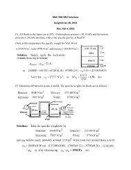
Example Problem 1SOLUTION:• Treating the entire beam as a rigidbody, determine the reaction forcesFor the timber beam <strong>and</strong> loadingshown, draw the shear <strong>and</strong> bendmomentdiagrams <strong>and</strong> determine themaximum normal stress due tobending.• Section the beam at points nearsupports <strong>and</strong> load application points.Apply equilibrium analyses onresulting free-bodies to determineinternal shear forces <strong>and</strong> bendingcouples• Identify the maximum shear <strong>and</strong>bending-moment from plots <strong>of</strong> theirdistributions.• Apply the elastic flexure formulas todetermine the correspondingmaximum normal stress.
SolutionSOLUTION:• Treating the entire beam as a rigid body, determinethe reaction forcesfrom F = 0 = M : R = 46kN R 14kN∑ ∑ =yB• Section the beam <strong>and</strong> apply equilibrium analyseson resulting free-bodies∑ = 0∑ M = 01− 20 kN −V1= 0( 20kN)( 0m) + M = 0 M = 0B1V1D= −20kN1F y∑ =0F y( )( ) m− 20 kN −V2=0V2= −20kN∑ M =2020kN2.5m+ M2=0M2= −50kN⋅VV34VV56= + 26kN= + 26kN= −14kNMMM= −14kNM3456= −50kN⋅ m= + 28kN ⋅ m= + 28kN⋅ m= 0
Solution• Identify the maximum shear <strong>and</strong> bendingmomentfrom plots <strong>of</strong> their distributions.Vm= 26 kNM=M=50kN ⋅m= m B• Apply the elastic flexure formulas todetermine the correspondingmaximum normal stress.S( 0.080m)( 0.250 ) 21 2b =16 6m−63= h= 833.33×10mσ mM3B50×10N ⋅m=833.3310−6 m3×= Sσ m=60.0×10⁶Pa
Example Problem 2Draw the shear <strong>and</strong> bending moment diagrams for the beam <strong>and</strong>loading shown, <strong>and</strong> determine the maximum absolute value (a) <strong>of</strong> theshear <strong>and</strong> (b) <strong>of</strong> the bending moment.Slide 8
Slide 9
Relations Between F, V, <strong>and</strong> M• For beams with more complicated loading, it is helpful to develop arelationship between load, shear <strong>and</strong> bending moment.Following our signconvention, W ispositive downwards!• Sum forces in the vertical direction.∑ F = − ( + Δ ) − Δ xyV V V w = 0dVdx−w⇒ΔV= −wΔx= or V −V= − wdxDCxD∫xCSlide 10
Relations Between F, V, <strong>and</strong> M cont’d• Sum forces in the vertical direction.∑Δx2 =( M + ΔM) − M −VΔx+ wΔx0M C=1ΔM= VΔx−2( Δx) 2• Neglect (Δx) 2 term since it is much smaller thanΔx term.wdM =dxVorMD−MC=xxD∫CVdxSlide 11
Example Problem 3Determine (a) the equations <strong>of</strong> the shear <strong>and</strong> bending moment curvesfor the beam <strong>and</strong> loading shown, <strong>and</strong> (b) the maximum absolute value<strong>of</strong> the bending moment in the beam.Slide 12
Slide 13
• Sample problem 5.3 inBeer’s book (v 5)Example 4Slide 14
<strong>Shear</strong> - Review• So far only dealt with normal stresses caused by bending moments.• This chapter deals with shear stress caused by shear forces.Line <strong>of</strong> failureSlide 15
<strong>Shear</strong> Stress in <strong>Beams</strong>Slide 16• Consider the effects <strong>of</strong> shear force (V).• Already know how to find resulting axial force <strong>and</strong>moment due to stress σ x from Chapter 5.• We have two more equations for shear stress:– Total shear force in the y-direction:– Total shear force in the z-direction: ∫ τ xz dA = 0∫τ xydA∫ 0= V
<strong>Shear</strong> Stress in <strong>Beams</strong> cont’d• Consider a cantilever beam composed <strong>of</strong> separate planks clampedat one end:Pure bending<strong>Shear</strong> force• <strong>Shear</strong> force causes tendency to “slide.”• Stresses are equal in horizontal <strong>and</strong>vertical directions.Slide 17
<strong>Shear</strong> Stress: Horizontal• Let us consider the horizontal component (τ xz = τ zx ).• Cut a section with cross-sectionalarea a at a distance y 1 above thecentroid.FBD →Slide 18
<strong>Shear</strong> Stress: Horizontal cont’d• ΔH is the horizontal shearing force.• Element width is Δx.• Sum forces in x-direction:∑ Fx= ΔH+ ∫ σC−• Recall:∫ ( σ) Dda = 0aσ =MyI• Solve for ΔH <strong>and</strong> use equation for σ:ΔH=⎛M−MI⎛MD CD C∫ ( σD−σC) da =∫ ⎜ ⎟yda= ⎜∫aa⎝⎞⎠⎝−MI⎞⎟⎠aydaSlide 19
<strong>Shear</strong> Stress: Horizontal cont’d• Recall first moment, Q, is defined as:Q = ∫ yda• The term M D -M C can be rewritten as:aMD− MC= ΔM=dMdxΔx= VΔx• Applying this to our equation for ΔH:ΔH=VQIΔx• We can rearrange this to define horizontal shear per unit length, q,called shear flow.ΔHVQq = =ΔxISlide 20
Side Note on Q• Q is the definition <strong>of</strong> the centroid for the area above y 1 ,Q= ∫ayda=a ywhere y bar is the distance between the centroid <strong>of</strong> the shadedsection <strong>and</strong> the centroid <strong>of</strong> beam cross-section.Slide 21
<strong>Shear</strong> Stress: Vertical• Now, let us consider the vertical component (τ xy = τ yx ).• We can calculate the average vertical shear stress on the cross-section.ΔH⎛VQ⎞⎛1 ⎞ VQτAVE= = ⎜ Δx⎟⎜⎟ = =τΔA⎝ I ⎠⎝tΔx⎠ Itτ AVE=VQItAVESlide 22
<strong>Shear</strong> Stress: Vertical cont’d• So, where is τ AVE maximum <strong>and</strong> minimum?– Use Q to find out.– Q = 0 at top <strong>and</strong> bottom surfaces– Q = maximum somewhere in betweenmax normal stressshear stress = 0max shear stressnormal stress = 0max normal stressshear stress = 0Slide 23
<strong>Shear</strong>ing Stress in Common Shapes• Rectangular cross-section ( ) ( ) (2 2Q = Ay = b c − y c + y = b c − y )1212τxy=VQIb=2 2( c − y ) 3V2 2= ( c − y )V b2 2b 4bc3( b( 2c)/12) 43τ xy3V⎛ y⎜1−2A⎝ c2=2⎞⎟ ⎠τ max=3VV2ASlide 24
<strong>Shear</strong>ing Stress in Common Shapes cont’d• <strong>Beams</strong> with flanges– Vertical shear stresses are larger in the web than in the flange.– Usually only calculate the values in the web.– Ignore the effects <strong>of</strong> the small fillets at the corners.– Flanges have large horizontal shear stresses, which we will learn how tocalculate later on.FlangeWebSlide 25
Example Problem 5A beam having the cross section shown is subjected to a vertical shearV. Determine the horizontal line along which the shearing stress ismaximum.Slide 26
Slide 27
Example Problem 6For the beam <strong>and</strong> loading shown, consider section n-n <strong>and</strong> determinethe shearing stress at (a) point a, (b) point b.Slide 28
Slide 29