Download - Acutronic
Download - Acutronic
Download - Acutronic

You also want an ePaper? Increase the reach of your titles
YUMPU automatically turns print PDFs into web optimized ePapers that Google loves.
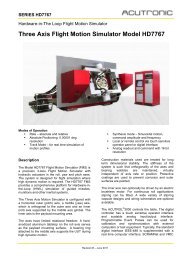
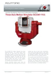
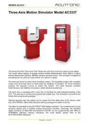
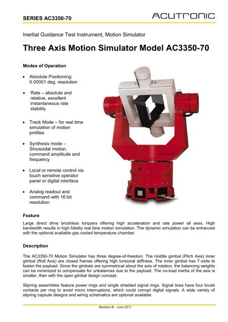
SERIES AC3350-70Inertial Guidance Test Instrument, Motion SimulatorThree Axis Motion Simulator Model AC3350-70Modes of OperationAbsolute Positioning:0.00001 deg. resolutionRate – absolute andrelative, excellentinstantaneous ratestabilityTrack Mode – for real timesimulation of motionprofilesSynthesis mode –Sinusoidal motion,command amplitude andfrequencyLocal or remote control viatouch sensitive operatorpanel or digital interfaceAnalog readout andcommand with 16 bitresolutionFeatureLarge direct drive brushless torquers offering high acceleration and rate power all axes. Highbandwidth results in high fidelity real time motion simulation. The dynamic simulation can be enhancedwith the optional available gas cooled temperature chamber.DescriptionThe AC3350-70 Motion Simulator has three degree-of-freedom. The middle gimbal (Pitch Axis) innergimbal (Roll Axis) are closed frames offering high torsional stiffness. The inner gimbal has T-slots tofasten the payload. Since the gimbals are symmetrical about the axis of rotation, the balancing weightscan be minimized to compensate for unbalances due to the payload. The no-load inertia of the axis issmaller, then with the open gimbal design concept.Slipring assemblies feature power rings and single shielded signal rings. Signal lines have four brushcontacts per ring to avoid micro interruptions, which could corrupt digital signals. A wide variety ofslipring capsule designs and wiring schematics are optional available.Revision B – June 2011
SERIES AC3350-70The ACUTROL ® 3000 controls the table. The digital controller has a touch sensitive operator interfaceand scalable analog input/output interface. Programmable Event Pulses can be used for calibrationand synchronization with external computers or test equipment. Optionally, the standard digitalinterfaces, Ethernet (TCP/IP) and IEEE-488 can be supplemented with real time reflective memoryinterfaces SCRAMNet or VMIC.DimensionsUnit under Test (UUT)Height, maxHeight of outer axisWidth across outer axisBase, diameterInner Gimbal clearanceT-slotsPayload, nominal (peak)Clearance envelopeElectrical lines to UUT2’715 mm1’890 mm2’000 mm1’000 mm550 mm x 550 mmSeized for M6 bolts30 kg, (100) 2 kgm 2 nominal550 mm cube70 lines total: 4 x 20 A6 x 6 A60 x 2 AROLL, inner axis PITCH, middle axis YAW, outer axisOrthogonality 5 arc sec 5 arc secWobble 2 arc sec 3 arc sec 3 arc secDynamic ParametersAngular freedom continuous continuous continuousPositioning accuracy 1.5 RSS arc sec 2 RSS arc sec 1.5 RSS arc secPosition resolution 0.00001 deg 0.00001 deg 0.00001 degRate range +/-900 deg/sec +/-400 deg/sec +/-300 deg/secRate resolution(command) 0.00001 deg/sec 0.00001 deg/sec 0.00001 deg/secRate accuracy 0.0010% 0.0010% 0.0010%Acceleration, with load 2kgm 2 10’000 deg/sec 2 2’000 deg/sec 2 1’800 deg/sec 2Bandwidth (-90deg) 50 Hz 22 Hz 30 HzOptions• Digital interface in addition to the std. IEEE-488 and Ethernet (TCP/IP)optional available are: SCRAMNet, or VMIC• Temperature chamber range –40 deg C to 100 deg C• Non standard sliprings• Special UUT adaptersFor further information, contact:ACUTRONIC Switzerland LtdRosengartenstrasse 258608 Bubikon, Switzerlandmarketing@acutronic.chwww.acutronic.com