Download - Acutronic
Download - Acutronic
Download - Acutronic

Create successful ePaper yourself
Turn your PDF publications into a flip-book with our unique Google optimized e-Paper software.
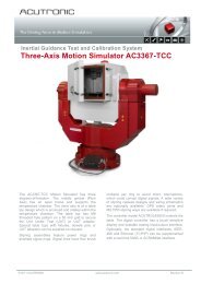
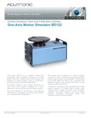
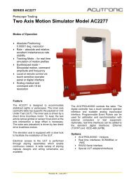
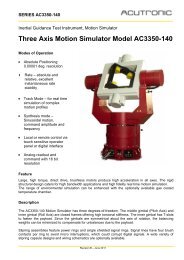
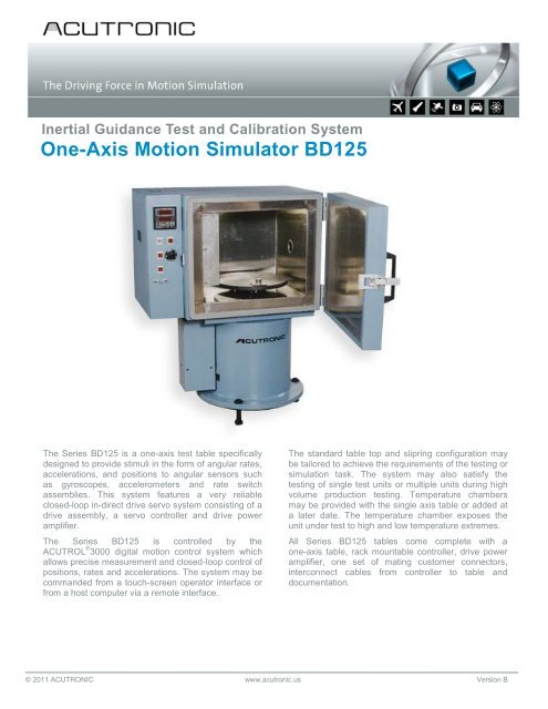
Inertial Guidance Test and Calibration SystemOne-Axis Motion Simulator BD125The Series BD125 is a one-axis test table specificallydesigned to provide stimuli in the form of angular rates,accelerations, and positions to angular sensors suchas gyroscopes, accelerometers and rate switchassemblies. This system features a very reliableclosed-loop in-direct drive servo system consisting of adrive assembly, a servo controller and drive poweramplifier.The Series BD125 is controlled by theACUTROL ® 3000 digital motion control system whichallows precise measurement and closed-loop control ofpositions, rates and accelerations. The system may becommanded from a touch-screen operator interface orfrom a host computer via a remote interface.The standard table top and slipring configuration maybe tailored to achieve the requirements of the testing orsimulation task. The system may also satisfy thetesting of single test units or multiple units during highvolume production testing. Temperature chambersmay be provided with the single axis table or added ata later date. The temperature chamber exposes theunit under test to high and low temperature extremes.All Series BD125 tables come complete with aone-axis table, rack mountable controller, drive poweramplifier, one set of mating customer connectors,interconnect cables from controller to table anddocumentation.© 2011 ACUTRONIC www.acutronic.us Version B
Unit Under Test (UUT)Mass1‘000 lbs (454 kg)Inertia 3.89 ft-lb-sec 2Maximum envelope12 in dia. x 13 in (305 mm x 330 mm)Table top diameter14 in dia.(356 mm dia)Sliprings to UUTsignal 24 ways, 2 amps(custom options available)12 inUUT13 inSpecificationsAngular freedomPositionAccuracyCommand resolutionRepeatabilitycontinuous1 arc sec RSS0.00001 deg± 0.1 arc secRateRange1,000 deg/secStability over 360 deg 0.001Command resolution0.00001 deg/secDynamicBandwidth (no load)25 Hz at -3dB Gain w/o chamberAcceleration (no load) 4,200 deg/sec 2MechanicalWobbleMajor Simulator DimensionsSimulator (L x W x H)Payload / table top height (from floor)Temperature Chamber (TC)Working volumeTemperature rangeTemperature stability (working volume)Cooling/heating gradients-LN 2 (TCN)-CO 2 (TCC)-Mechanical refrigeration (TCM)10 arc sec RMS31 in x 22 in. x 51 in w/chamber29 in (737 mm) w/o chamber / 34 in (864 mm) w/chamber14 in dia. x 13 in height-55°C to +85°C± 1.0°C5°C/min (heating and cooling)5°C/min (heating and cooling)5°C/min (heating)/1.5°C/min (cooling)Options• Temperature chamber, cooled and heated by customer supplied air flow• Increased/decreased rate/acceleration/G-range/bandwidth for higher performance/lower cost• Custom UUT mounting arrangements and fixtures• Custom tabletop/mounting surfaces and/or boom• Mechanical brake, Stow Lock, or Slow Motion Clamp• Optional real time computer interfaces; SCRAMNet GT200, or VMIC• LabVIEW user interface for playback and recording of motion profiles with data acquisition system• Installation support, training and calibration• Customized sliprings up on request: High pressure gas line or fluid joints, 20 amp lines, 5 amp lines, 3 amp lines, RF rotary joints, FiberOptic rotary jointsThe specifications identified in this data sheet are representative of standard systems. To satisfy customer specific requirements ACUTRONIC isable to design systems with specifications that are increased or decreased relative to standard systems.© 2010 ACUTRONIC www.acutronic.us Version A