Fuel Cell Systems Explained - from and for SET students
Fuel Cell Systems Explained - from and for SET students
Fuel Cell Systems Explained - from and for SET students

Create successful ePaper yourself
Turn your PDF publications into a flip-book with our unique Google optimized e-Paper software.
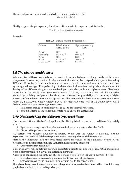
The second part is constant <strong>and</strong> is included in a real, practical OCV.Finally we get a simple equation, that fits excellent results in respect to real fuel cells.Example:3.9 The charge double layerWhenever two differnet materials are in contact, there is a build-up of charge on the surfaces or acharge transfer over the junction. In electrochemical systems, the charge double layer is <strong>for</strong>med bydiffusion effects, by the reactions between electrons in the electrodes <strong>and</strong> ions in the electrolyte <strong>and</strong>by an applied voltage. The probability of electrochemical reaction taking place depends on thedensity of the different charges at the double layer; more charges lead to higher current. The chargeseperation at the double layer generates an electric voltage, in case of a fuel cell the activationovervoltage. Adding catalysts to the electrodes increases the probability of a reaction; a highercurrent canflow without such a build-up voltage. The charge double layer can be seen as an electriccapacitor, a storage of electric energy. Due to the capacitive behaviour of the double layer, will afuel cell react on a cureent change in two steps.1. Immediate change in operating voltage due to the internal resistance.2. Smoothly move to the final equilibrium value due to the capacitance.3.10 Distinguishing the different irreversebilitiesHow can the different kinds of voltage losses be distinguished in respect to conditions they mainlyoccur? Eperiments using specialised electrochemical test equipment such as half cells Electrical impedance spectroscopyAC current with variable frequency is applied to the cell, the voltage is measured <strong>and</strong> theimpedance is calculated. Higher frequencies means less impedance of the capacitors.Plots of the impedance over the frequencies shows the values of the equivalent electric circuitelements, thus the mass transport <strong>and</strong> activation losses can be seperated. Current interrupt techniqueis an alternative, which delivers accurate quantitative results but also quick qualitative indications.It can be per<strong>for</strong>med using low cost electronic equipment.A current is applied <strong>and</strong> suddenly cut of. The voltage will follow in the above mentioned steps:1. Immediate change in operating voltage due to the internal resistance.2. Smoothly move to the final equilibrium value due to the capacitance.The ohmic losses <strong>and</strong> the activation overvoltage can be seperated <strong>from</strong> each other. The followinggraph shows a sketch of the voltage change.