Fuel Cell Systems Explained - from and for SET students
Fuel Cell Systems Explained - from and for SET students
Fuel Cell Systems Explained - from and for SET students

Create successful ePaper yourself
Turn your PDF publications into a flip-book with our unique Google optimized e-Paper software.
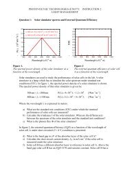
-<strong>Fuel</strong> <strong>Cell</strong> <strong>Systems</strong> <strong>Explained</strong>-(Summary of chapter 1-4, 7, 8)1. Introduction1.1 Hydrogen fuel cells – basic principlesDefinition: A fuel cell is an electrochemical device that converts a supplied fuel to electrical energy<strong>and</strong> heat continuously, so long as reactants are supplied to its electrodes. Neither the electrodes northe elctrolyte are consumed by the operation of the cell (page 17).Example: Acid electroclyte fuel cellAnode: hydrogen gas ionises, releasing electrons <strong>and</strong> creating H + ions.2H 2 → 4 H + + 4e -Cathode:oxygen reacts with the electrons <strong>from</strong> the electrode <strong>and</strong> H + ions <strong>from</strong>the electrolyte to <strong>for</strong>m water.O 2 + 4 H + + 4e - → 2H 2 OAn acid electrolyte allows only H + ions to pass through. The e - have to pass through an externalelectric circuit. Certain polymers also allows only positiv ions to pass <strong>and</strong> can be used aselectrolyte, so called proton exchange membranes PEM.Note:For all primary batteries <strong>and</strong> there<strong>for</strong>e <strong>for</strong> fuel cells, are the electrons flowing <strong>from</strong> the anode to thecathode. Thus the anode is electrical negative <strong>and</strong> the cathode is electrical positive.Cations: positive ionsAnions: negative ions1.2 What limits the current?First the activation energy has to be exceeded <strong>for</strong> an exothermic reaction taken place. If teprobability of a molecule having enough energy is low, the reaction rate is slow.The reaction rate can be accelerated by using a catalyst raising the temoerature increasing the electrode surface area (<strong>for</strong> fuel cells)
The chemical reactions have to take place at the surface of the electrodes, due to removing orsupplying electrons. These reactions of the fuel with the electrolyte at the electrode is called a threephase contact. The reaction rate is propotional to the effective surface area of the electrodes.Requirements <strong>for</strong> the electrodes: high effective surface area (highly porous material) incoporate with a catalyst endure high temperatures in a corrosive environment1.3 Connecting cells in series – bipolar plateA single fuel cell generates only a small voltage drop (0.7V). In order to generate a useful voltageseveral cells are connected into series. Such a connection is called a stack. The simplest way tocreate a series connection would be to connect the edge of each anode to the cathode of the nextcell. The problem of such a system is, that the electrons would have to travel through the wholeelectrode, thus the ohmic resistance would be relative high.A better alternative are bipolare plates. These plates are made of a conducting material (Graphite,stainless steel, some ceramic materials) with connections areas over the surface as well as gassupply channels <strong>for</strong> the electrodes. The bipolare plates are complex parts <strong>and</strong> difficult tomanufacture, thus the most expensive parts of a fuel cell.In order to optimize the design of bipolare plates several aspects counteracts each other: good electric contact requires a large contact area <strong>and</strong> a thin plate, to reduce the ohmicresistance. This lead to small narrow gas channels thus bad gas distribution over the electrode <strong>and</strong> lowgas flow rates or high operation pressueres.1.4 Gas supply <strong>and</strong> coolingA major problem of manufacture fuell cells is leakage of the reactant gases. In order to seperate thegases strictly <strong>from</strong> each other are the electrrodes sealed at the edges with a gasket.External manifolds:gas is supplied through an external lid, that covers the whole side of the stack.+ simple structure- cooling of the system. Needs a higher air supply rate <strong>for</strong> cooling. Makes the cell more inefficient- higher leakage probability. The gasket is not pressed evenly onto the electrodes.Internal manifolds:gas is supplied into the stack through additional supply channels in the bipolare plates.- That requires larger <strong>and</strong> more complex bipolare plates with extra channels <strong>for</strong> the reactants supply.These channels are connected to the the gas channels along the electrodes.+ solid stack with the gases fed in at the same ends of the electrical connections.+ additional cooling channels along the bipolare plates.+ lower leakage probability
1.5 <strong>Fuel</strong> cell typesBesides the practical issuses fuel cells have to fundamental technical problems: slow reaction rate, low current <strong>and</strong> power hyrogen is not readily available as fuelThere are six viable systems of fuel cells:TypeAlkalineAFCProton exchangemembranPEMFCDirect methanolDMFCPhosporic acidPAFCMoltencarbonateMCFCMobileIonOperatingtemp. [°C]Anode <strong>and</strong> cathodereactionsApplication <strong>and</strong> notesOH - 50-200 Space vehiclesH + 30-100 2H 2 →4H + +4e - (a)O 2 +4H + +4e - →2H 2 O (c)Vehicles <strong>and</strong> mobileapplications, low power CHPH + 20-90 Portable electronic systems,low power but long runningtimeH + ca. 220 For small CHP plants(hundreds of kW), firstcommercial oneCO 32-ca. 650For medium to large CHP (upto MW)Solid OxideSOFCO 2- 500-1000 For all sizes of CHP (<strong>from</strong> kWto multi MW)Advantages <strong>and</strong> disadvantages are discussed later.1.6 Other cells – Some fuel cells, some not1. Biological fuel cellsuse an organic fuel, like methanol or ethanol, <strong>and</strong> enzymes to produce energy. Not yetcommercial2. Metal air cells (batteries)at the negative electrode the metal reacts with an alkaline electrolyte to <strong>for</strong>m metal oxide orhydroxide. The released eelctrons pass though an external electric circuit to the air cathode,where water <strong>and</strong> oxygen reacts to hydroxyl ions (see alkaline fuel cell). Metal oxide isdissolved into the electrolyte, which have to be renewed after some time. Consumption ofanode <strong>and</strong> electrolyte.Very good energy densitiy: commercial <strong>for</strong> low power applications with long running time.Research <strong>for</strong> higher power <strong>for</strong> electric vehicles.3. Reodx flow cells or regenerative fuel cellsFor charging the reactants are removed <strong>from</strong> the electrodes <strong>and</strong> stored in a tank. Fordischarging the electrolytes are supplied back to the electrodes. Is used <strong>for</strong> very largecapacity rechargeable batteries. The electrocolyte changes during operation <strong>and</strong> the systemcannot work idenfinitely.
1.7 Other parts of fuel cellsThe core of a fuel cell power system consists of electrodes, electrolyte <strong>and</strong> bipolar plate. Theadditional parts, also called balance of plant BOP, make a up a large contribution to the wholesystem. They depent on the type of the fuel cell <strong>and</strong> the used fuel. Circulation of the reactants: pumps, blowers, compressors, intercoolers Electricity output: power electronics, as DC/DC converters, DC/AC inverters Electric motors to drive the devices <strong>Fuel</strong> storage <strong>Fuel</strong> processing, desulphurisation Control valves <strong>and</strong> pressure regulation Controll unit, especially <strong>for</strong> start-up <strong>and</strong> shutdown at high temperature devices Cooling system Heat exchanger <strong>and</strong> pre-heater <strong>for</strong> high temperature cells humidification of reactant in PEM1.8 Figures used to compare systemsFor the fuel cell: Current density to compare electrodes <strong>and</strong> electrolytes Specific operating voltage (0.6 – 0.7V) Power densityNote: Electrodes do not scale up properly. If the area is doubled, the current will often not double.The reasons are not yet understood, but realted to even delivery of reactants <strong>and</strong> removal ofproducts <strong>from</strong> all over the face of the electrode.For the whole generation system: Power density Specific power cost per kWh Lifetime (difficult to specify)Per<strong>for</strong>mance <strong>and</strong> MTBF (mean time between failures) depends on the age of the electrode <strong>and</strong>electrolyte. 'Percentage deterioration per hour' Gradual decline in voltage in mV/1000h (somtimes) Efficiency1.9 Advantages <strong>and</strong> applicationsDisadvantages: mainly the costsAdvantages: EfficiencyGenerally more efficient than combustine engines. Independant of the size of the system.Useful <strong>for</strong> small local CHP plants SimplicityThe basics of a fuel cell is very simple, with few moving parts. Can lead to highly reliable<strong>and</strong> long-lasting systems. Low emissionsUsing hydrogen leads to pure water as by-product. A fuel cell can operate with zeroemissions. CO 2 emission <strong>for</strong> H 2 production is not considered. Silence<strong>Fuel</strong> cells operate very silent, even with extensive fuel processingUsing H 2 as fuel can count <strong>for</strong> disadvantage or advantage. In a future perspective with a limitationof fossil fuels, H 2 will be a major fuel.
<strong>Fuel</strong> cells can be used successfully in CHP plants or in mobile power systems, like vehicles orelectronic equipment.2. Efficiency <strong>and</strong> open circuit voltgage2.1 Energy <strong>and</strong> the EMF of the hydrogen fuel cellThe chemical energy in <strong>and</strong> output of a fuel cell is not easily derived. Parameters as enthalpy,Hemholtz function, Gibbs free energy or exergy are used. Gibbs free energyenergy available to do external work, neglecting any work done by changes in pressure<strong>and</strong>/or volume. In case of a fuel cell are the moving electrons in the electric circuit meantwith external work. Exergyis all external work that can be extracted, including that due to pressure <strong>and</strong> volume changes EnthalpyGibbs free energy plus the energy connected to the entropy.The chemical energy has similarities to mechanical potential energy.1. Reference energy level can be defined as almost anywhere. Working with chemical reactionsthe reference level with zero energy is defined as pure elements, in the normal state, atst<strong>and</strong>ard conditions (25°C or 298.15K, 0.1MPa).Using this convention, the terms 'Gibbs free energy of <strong>for</strong>mation', G f , <strong>and</strong> 'enthalpy of<strong>for</strong>mation' is used. In case of a hydrogen fuel cell operating at st<strong>and</strong>ard temperature <strong>and</strong> pressurethe Gibbs free energy of <strong>for</strong>mation at the input is zero (useful simplification).2. Energy difference between in <strong>and</strong> output is the important value. In a fuel cell, the change ofthe Gibbs free energy of <strong>for</strong>mation, ΔG f , is the energy released. Given by the equationΔG f = G f of products - G f of reactantsIt is convenient to use the molar specific Gibbs free energy of <strong>for</strong>mation, written g̅ f.
Note:The mole is a measure of the amount of a substance in respect to its molar mass.H 2 molar mass: 2amu1 mole = 2gH 2 O molar mass: 18amu1 mole = 18gOne mole of a substance always has the same number of molecules, given by the Avogardro'snumber N = 6.022 x 10 23 .The Faraday's constant gives the charge of one mole of electrons.F = N x e = 6.022 x 10 23 x 1.602 x 10 -19 C = 96485 CUsing the basic reaction of the hydrogen/oxygen fuel cell, it can be seen that one mole of H 2 <strong>and</strong>half a mole O 2 deliver one mole of H 2 O. However, note that the Gibbs free energy of <strong>for</strong>mation isnot constant. It depends on the temperature <strong>and</strong> state (liquid or gas). When the values are negative itmeans that energy is released.Electromotive <strong>for</strong>ce EMF = reversible open circuit voltage OCFIn a reversible process in the fuel cell, all Gibbs free energy would be converted into electricalenergy. The basic reaction provides two electrons to the electric circuit <strong>for</strong> each molecule of H 2used. So <strong>for</strong> one mole of H 2 , 2N of electrons pass through the circuit.Flowing charge: -2Ne = -2F [C]The electric work done equals the product of charge times voltage E. In a reversible process, theelectric work also equals the Gibbs free energy released.Given is the electromotive <strong>for</strong>ce EMF or reversible open circuit voltage of the hydrogen fuelcell.In practice the voltage would be lower, due to the fact that some irreversibilities also apply evenwhen no current is drawn <strong>from</strong> the cell.In generalwith z is the number of electrons per molecule of fuel.2.3 Efficiency <strong>and</strong> efficiency limitsThe Gibbs free energy is the part of chemical energy which is converted into electrical energy.However, it is insufficient to calculate the efficiency of a fuel cell only with this part of thechemical energy of the reactants by taken the irreversibilities into account, due to the fact that theGibbs free energy depends on the temperature, the pressure <strong>and</strong> other factors.In order to compare a fuel cell with other fuel burning technologies, is the maximum possbileefficiency derived by the ratio of the electrical energy produced per mole of fuel <strong>and</strong> the change ofenthaply of <strong>for</strong>mation, that means the energy amount released as heat by burning the fuel.The maximum possible efficiency level, also named thermodynamic efficiency, is given byη max = Δg̅ f / Δh̅ f x 100%Note that Δh̅ f depends on the state of the substance, liquid or gas. For gas it is called the higherheating value HHV, <strong>for</strong> liquid it it called the lower heating value LHV. The difference betweeenboth is the molar enthalpy of vaporisation. Any statement of efficiency should say whether it relates
to the HHV or LHV. If the in<strong>for</strong>mation is not given, probably the the LHV is used.Table 2.2 shows the theoretical efficiency limit of a hydrogen fuel cell in respect of the operatingtemperature. However in practice there are some differences. Voltage losses are less at higher temperatures, so the fuel cell voltage is higher at hightemperatures. Waste heat of higher temperature cells can be used. <strong>Fuel</strong> cells do not always have a higher efficiency limit than heat engines.The mentioned decline in maximum possible efficiency with temperature <strong>for</strong> the hydrogen fuel cellis not exactly occur <strong>for</strong> other cell types.2.4 Efficiency <strong>and</strong> the fuel cell voltageThe operation voltage of a fuel cell can be related to its efficiency.For 100% efficient hydrogen fuel cell, the enthalpy of <strong>for</strong>mation is converted into electric energy.Considering the fact that not all fuel is used during operation, the fuel utilisation coefficient isintroduced.This is equivalent to the ratio of fuel cell current <strong>and</strong> the current that would be obtained if all thefuel were reacted. The fuel cell efficiency in respect to the HHV is there<strong>for</strong>e given byA good estimation <strong>for</strong> µ f is 0.95.
2.5 The effect of pressure <strong>and</strong> gas concentration2.5.1 The Nernst equationAs mentioned in 2.1 is the Gibbs free energy change dependant on the temperature <strong>and</strong> in a morecomplex relation on the reactant pressure <strong>and</strong> concentration.In a chemical reaction every reactant <strong>and</strong> product have their own 'activity'. In case of an ideal gas,the 'activity' is definded asa = P / P 0withP: partial pressure of the gasP 0 : st<strong>and</strong>ard pressure, 0.1MPaThe activity of a gas is proportional to its partial pressure. The produced water in a fuel cell caneither be a liquid or steam. In case of liquid water, it is a reasonable approximation to assumea H2O =1.The activities of the reactants <strong>and</strong> products of a chemical reactionjJ + kK → mMmodify the Gibbs free energy change, given by the equationwith Δg̅ f 0 : molar Gibbs free energy change at st<strong>and</strong>ard pressure (<strong>from</strong> gas tables)R = 8.314 j/Kmol molar gas constantT: temperatureIt can be seen, that when the activities of the reactants increase, Δg̅ f becomes more negative, somore energy is released. On the other side, if the activity of the product increase, Δg̅ f becomes lessnegative, so less energy is released.Substitute this equation in the equation of the EMF gives the Nernst equation.with E 0 : EMF at st<strong>and</strong>ard pressureThe Nernst equation gives the EMF dependant on the product <strong>and</strong> reactant activities. The derivedEMF, also called Nernst voltage, is the reversible cell voltage that would exist at a giventemperature <strong>and</strong> pressure.Using the rules of logarithmic functions an the definition of activity, the equation can be simplified.In nearly all cases will be the pressures partial pressures, that is, the gases will be part of a mixture.It often appears that the pressures at cathode <strong>and</strong> anode are the same, to simplify the design.Note:In a mixture of gases, the total pressure is the sum of all the partial pressures of the components.From the gas law equation it can be shown, that the volume fraction, molar fraction <strong>and</strong> pressurefraction of a gas mixture are all equal.Example: CH 4 + H 2 O → 3H 2 + CO 2
The products are three parts of H 2 <strong>and</strong> one part of CO 2 by moles <strong>and</strong> volume. If thereaction takes place at 0.1MPa the partial pressures can be derivedP H2 = ¾ x 0.1MPa = 0.075MPaP CO2 = ¼ x 0.1MPa = 0.025MPa2.5.3 <strong>Fuel</strong> <strong>and</strong> oxidant utilisationAs air passes through a fuel cell, the oxygen is used, <strong>and</strong> so the partial pressure will reduce.Similarly, the fuel partial pressure will often decline, as the proportion of fuel reduces abd reactionproducts increase. That makes the logarithmic term in the Nernst equation smaller, <strong>and</strong> so the EMFwill fall. This circumstance will vary over the cell <strong>and</strong> will be worst at the fuel outlet as the fuel isused. Due to the conducting material of the bipolar plate the voltage is constant over the cell, thatmeans that the current will vary. The current density will be lower nearer the exit where the fuelconcentration is lower. The RT term indicates that the voltage drop due to fuel utilisation will begreater <strong>for</strong> high temperature fuel cells.A high system efficiency normally requires a high fuel utilisation. That counteracts the abovedescribed behaviour. The cell voltage, hence the cell efficiency will fall with higher fuel utilisation.There<strong>for</strong>e, fuel <strong>and</strong> oxygen utilisation is an important aspect in the system design <strong>and</strong> thus needscareful optimisation.2.5.4 System pressureWhen the system pressure is known, the Nernst equation can be rewritten, usingP H2 = αP with α constant depending on the molar masses <strong>and</strong> concentration of H 2P O2 = βP with α constant of O 2P H2O = δP with α constant of H 2 OasIt can be seen, thet the EMF of the fuel cell is depending on the system pressure P. A hihgherpressure leads to a higher voltage. For high temperature fuel cells, <strong>for</strong> example SOFC at 1000°C,the predictions of the Nernst equation correlate with practise. For lower temperatures, as in a PAFCat 200°C, the voltage change is even bigger. This occurs due to increasing pressure also reduces thelosses at the electrodes, especially at the cathode. A similar effect occurs <strong>from</strong> switching <strong>from</strong> air tooxygen (β). The voltage losses at the cathode decline <strong>for</strong> pure oxygen.
2.6 Summary reversible OCV or EMF max efficiencyη max = Δg̅ f / Δh̅ f x 100% efficiency of working H 2 fuel cell relative to HHV Nernst equationThe pressure <strong>and</strong> the concentration of the reactants affects the Gibbs free energy, <strong>and</strong> thusthe voltage, given by the Nernst equation.3. Operational fuel cell voltage3.1 IntroductionThe operating voltage of a fuel cell is always below the theoretical open circuit voltage derived inchapter 2. Figure 3.1 shows the per<strong>for</strong>mance of a typical hydrogen fuel cell operating at 70°C <strong>and</strong>normal air pressure.Note: even the open circuit voltage is less than the theoretical value there is a rapid initial fall afterwards the voltage falls less rapidly <strong>and</strong> mor linear there may be a higher current density at which the voltage falls rapidly againFor a higher temperature fuel cell the graph changes. The reversibel 'no loss' voltage is smaller, butthe difference between the 'no loss' voltage <strong>and</strong> the operational voltage is less, due to the initialvoltage drop is significant smaller.
Figure 3.2 shows the per<strong>for</strong>mance of a SOFC operating at 800°C.Note: the OCV is equal or just a litle less than the theoretical vallue the intial fall in voltage is very small, <strong>and</strong> the graph more linear there may be a higher current density at which the voltage falls rapidly againThe focus of chapter 3 is on the questions: What causes the voltage to fall below the reversiblevalue <strong>and</strong> how can this situation be improved?3.2 TerminologyCommonly five terms are used to describe this voltage difference: Overvoltage or overpotential Polarisation Irreversibility Losses Voltage dropEvery term is used in the book!3.3 <strong>Fuel</strong> cell irreversibilities – causes of voltage dropThe characteristic shape of the voltage/current density graphs results <strong>from</strong> four majorirreversibilities.1. Activation lossescaused by the slowness of the reactios at the electrode. Voltage is used to drive the reactions. Nonlinear.2. <strong>Fuel</strong> crossover <strong>and</strong> internal currentscaused by unused fuel diffusion <strong>and</strong> electron flow through the electrolyte. Small losses.3. Ohmic or resistive lossescaused by the ohmic resistance of the electrodes <strong>and</strong> interconnections.4. Mass transport or concentration lossescaused by a change in the reactants concentration at the surface of the electrodes. Modelled by theNernst equation.
3.4 Activation losses3.4.1 The Tafel equationThe Tafel equation <strong>and</strong> plots are experimental results. Tafel observed, that the overvoltage at thesurface of an electrode follows similar pattern <strong>for</strong> different chemical reactions: The plot of thevoltage against the logarithmen of the current density is approximatly a straight line.Tafel plotsTafel equationThe constant A is higher <strong>for</strong> slow chemical reactions. The exchange current density i 0 is higher ifthe reaction is faster. The current density i 0 can be considered as the current density at which theovervoltage begins to move <strong>from</strong> zero. The equation is only true <strong>for</strong> i 0 > i.3.4.2 The constants in the Tafel equationFor a hydrogen fuel cell, the constant A is given bywith α: charge transfer coefficientThe charge transfer coefficient varies <strong>from</strong> 0 to 1 <strong>and</strong> amount of electrical energy that is used tochange the electrochemical reaction rate. The value of α depends on the electrode material.The impact of the temperature in the equation is far outweighted by the effect of i 0 with changingtemperature <strong>and</strong> thus is not considered. Indeed we shall see, that the key to making the activationovervoltage as low as possible is i 0 , which can vary by several orders of magnitude.Even at zero current density the electrochemical reaction at the electrodes is taken place, but thereverse reaction is also taken place at the same rate. There is an equilibrium.Thus, there is an continual <strong>for</strong>wards <strong>and</strong> backwards flow of electrons <strong>from</strong> <strong>and</strong> to the electrolyte.This current density is the exchange current density i 0 . If i 0 is high, that means, that the surface ofthe electrode is more active, <strong>and</strong> thus it is easier to direct the current densit in a particular direction.The exchange current density is crucial in controlling the per<strong>for</strong>mance of the fuel cell electrode <strong>and</strong>should be as high as possible.
In order to get the current instead of the voltage the Tafel equation is cahnged in the Butler-Vollmer equationThe importance of i 0 can be seen in the following graph <strong>for</strong> values of 0.01, 1.0 <strong>and</strong> 100mA/cm 2 .Measurements of i 0 shows a great variation in respect of the e;ectrode material. For hydrogen fuelcells are the values at the oxygen electrode (cathode) lower by a factor of 10 5 . There<strong>for</strong>e is theovervoltage at the anode negligible compared to the cathode.For other fuel cells, <strong>for</strong> example a DMFC, the anode overvoltage is not negligible. In these cases theequation <strong>for</strong> the total overvoltage combine the voltage drops at both electrodes. I can be expressedaswith3.4.3 Reducing the activation voltageIn order to reduce the activation voltage it is most important to increase i 0 . This can be done by Raising the cell temperature Using more effective catalysts Increasing the roughness of the electrode (increased surface) Increasing reactant concentration (pure O 2 instead of air)(more effective occupation of the surface by reactants) Increasing the pressure(more effective occupation of the surface by reactants)Increasing the value of i 0 . Has the effect of raising cell voltage by a constant amount at mostcurrents, <strong>and</strong> so lead to raising OCV. The last two points explain the difference between thearetical<strong>and</strong> practical OCV.In low <strong>and</strong> medium temperature fuel cells, activation overvoltage is the most importantirreversibility <strong>and</strong> cause a voltage drop at the electrodes. Mainly at the cathode <strong>for</strong> hydrogen fuel.At higher temperatures <strong>and</strong> pressures the activation overvoltage becomes less important.
3.5 <strong>Fuel</strong> crossover <strong>and</strong> internal currentsEven if the electrolyte is designed toconduct only ions, it always occurs that a small amount ofelectrons pass through it. In practical fuel cells the fact that a certain amount of fuel diffuse unusedthrough the electrolyte is more important. The unused fuel will react directly with oxxygen at thecathode <strong>and</strong> no current is produced. These effects – fuel crossover <strong>and</strong> internal current – areessentially equivalent. One diffused hydrogen molecule effects in the same way as two electrons ofinternal current. The amount of these losses will be very small in respect to the irreversebilities.However,, in low temoerature fuel cells it causes a very noticeable drop of OCV, about 0.2V (20%)<strong>for</strong> a PEM. Noticeable in the steep initial falls of the voltage plots.A small change in fuel crossover <strong>and</strong>/or internal current, caused <strong>for</strong> example, by a change inhumidity of the electrolyte, can cause a large change in the OCV.Measurements of the internal current are problematic, but can be done by the measurement of thefuel consumption. The consumption rate of hydrogen [moles/s] is related to the current by thefollowing equation.The equation of the cell voltage can be refined, including the internal current density i n .To conclude, the effect of internal current is much less <strong>for</strong> high temperature cells, because i 0 ismuch higher. For low temperature cells internal current <strong>and</strong> fuel diffusion is usually not of greatimportance in terms of operating efficiency, but it has a marked effect on the OCV.3.6 Ohmic lossesThe losses occured by the electrical resistance of the electrodes <strong>and</strong> the interconnection <strong>and</strong> by theresistance against the flow of ions in the eelctrolyte. The ohmic voltage loss is important in all typesof fuel cells, especially in SOFC, <strong>and</strong> is mainly caused by the electrolyte. However the electricalresistance of the electrodes <strong>and</strong> bipolar plates is not negligible.The voltage drop is given by Ohm's law, using the current density <strong>and</strong> the area-specific resistance.ΔV ohm = i x rwith i in [mA/cm 2 ]r in [kΩcm 2 ]There are three ways of reducing the internal resistance: highly conductiv electrode material design <strong>and</strong> material of the bipolar plate or interconnection electrolyte as thin as possible(but have to prevent shorting of the electrodes, wide enough to provide a flow of electrolyte,physical robust, due to electrodes are built on it)3.7 Mass transport <strong>and</strong> concentration lossesDue to the electrochemical reactions at the eelctrodes, hydrogen <strong>and</strong> oxygen are consumed. Thatleads to a change in concentration, which leads on the other h<strong>and</strong> to a change in partial pressure ofthe reactants, which results in a voltage drop over the cell. The pressure changes depend on thecurrent drawn <strong>from</strong> the cell <strong>and</strong> the physical characteristics of the gas supply system, relating to thefluid resistance, the flow rate <strong>and</strong> the design of the gas supply along the electrodes.There is no overall satisfactory analytical solution to this problem. One theoretical approach ismentioned, which shows the effect of reducing the partial pressure on the OCV.
Assumption:Introduction a limiting current density i 1 at which the hydrogen consumption rate is equal to themax. supply rate. At i 1 the pressure would have reached zero.P 1 is the pressure when i is zero. If we assume a linearly fall <strong>from</strong> P 1 to P(i 1 ), tha the pressure at anycurrent density is given bySubstitution in above equation delivers the voltage drop due to mass transport.The negative sign is due to the fact that it is a voltage drop.The term RT/2F will be different <strong>for</strong> each reactant <strong>and</strong> is in general substitute by the constant B.This theoretical approach has many limitations, like: supply of air instead of pure oxygen lower temperature cells mixed fuel production <strong>and</strong> removal of reaction products build-up nitrogen in air systemsAn empirical approach is more favourable, because it provides an equation which delivers muchbetter results <strong>and</strong> will be used in the rest of the chapter.With m is about 3x10 -5 V <strong>and</strong> n is about 8x10 -3 cm/mA.The mass transport or concentration losses are important when Hydrogen is supplied by a re<strong>for</strong>mer. The reaction rate on a dem<strong>and</strong> change is too slow. The supply at the air cathode is not well circulated. Build-up nitrogen can block the oxygen supply at high currents. Water is not removed qickly enough in PEMFC.3.8 Combining the irreversebilitiesThe operating voltage of a fuel cell at a current density i is given bywith E: reversible OCVi n : internal <strong>and</strong> fuel crossover equivalent current densityA: slope of the Tafel linei 0 : exchange current densitym & n: constants in the mass-transfer overvoltager: area-specific resistanceThis equation can be simplified, due to i n is usually very small <strong>and</strong> has little impact on operatinglosses of fuel cells at working currents, so it will be cancelled. The term of the activationovervoltage can be rewritten as
The second part is constant <strong>and</strong> is included in a real, practical OCV.Finally we get a simple equation, that fits excellent results in respect to real fuel cells.Example:3.9 The charge double layerWhenever two differnet materials are in contact, there is a build-up of charge on the surfaces or acharge transfer over the junction. In electrochemical systems, the charge double layer is <strong>for</strong>med bydiffusion effects, by the reactions between electrons in the electrodes <strong>and</strong> ions in the electrolyte <strong>and</strong>by an applied voltage. The probability of electrochemical reaction taking place depends on thedensity of the different charges at the double layer; more charges lead to higher current. The chargeseperation at the double layer generates an electric voltage, in case of a fuel cell the activationovervoltage. Adding catalysts to the electrodes increases the probability of a reaction; a highercurrent canflow without such a build-up voltage. The charge double layer can be seen as an electriccapacitor, a storage of electric energy. Due to the capacitive behaviour of the double layer, will afuel cell react on a cureent change in two steps.1. Immediate change in operating voltage due to the internal resistance.2. Smoothly move to the final equilibrium value due to the capacitance.3.10 Distinguishing the different irreversebilitiesHow can the different kinds of voltage losses be distinguished in respect to conditions they mainlyoccur? Eperiments using specialised electrochemical test equipment such as half cells Electrical impedance spectroscopyAC current with variable frequency is applied to the cell, the voltage is measured <strong>and</strong> theimpedance is calculated. Higher frequencies means less impedance of the capacitors.Plots of the impedance over the frequencies shows the values of the equivalent electric circuitelements, thus the mass transport <strong>and</strong> activation losses can be seperated. Current interrupt techniqueis an alternative, which delivers accurate quantitative results but also quick qualitative indications.It can be per<strong>for</strong>med using low cost electronic equipment.A current is applied <strong>and</strong> suddenly cut of. The voltage will follow in the above mentioned steps:1. Immediate change in operating voltage due to the internal resistance.2. Smoothly move to the final equilibrium value due to the capacitance.The ohmic losses <strong>and</strong> the activation overvoltage can be seperated <strong>from</strong> each other. The followinggraph shows a sketch of the voltage change.
To summarize the irreversibilities due to their importance in different conditions. Concentration <strong>and</strong> mass transport losses are important only at higher currents. The should bevery small in well designed systems. In low temperature hydrogen fuel cells activation overvoltage <strong>and</strong> ohmic losses areimportant <strong>Fuel</strong> cells using mixed fuel, as methanole, the activation overvoltage at anode <strong>and</strong> cathodedominates. In higher temperature fuel cells the ohmic losses are the major factor.4. Proton Exchange Membrane <strong>Fuel</strong> <strong>Cell</strong> PEMFCA PEMFC, also called solid polymer fuel cell, consists of an ion conducting polymer electrolytebonded at each side with a catalysed porous electrode. These membrane electrode assemblies MEAsare very thin <strong>and</strong> connected in series with bipolare plates. The mobile ion is an H + ion or a proton.The basic reactions are at the anode2H 2 → 4 H + + 4e -<strong>and</strong> at the cathodeO 2 + 4 H + + 4e - → 2H 2 OThe polymer electrolyte works at low temperature, so that the fuel cell can start very quickly.Further advantages are, that the design can be very compact, no corrosive fluid hazards are used <strong>and</strong>the cell works in every direction. This means that the PEMFC is very suitable <strong>for</strong> a wide range ofapplications, like vehicles <strong>and</strong> portable electronics, but can also be used in CHP power plants.Similarities <strong>for</strong> applications: electrolyte electrode structure <strong>and</strong> catalystDifferences <strong>for</strong> applications: water management cooling the fuel cell connecting the cells in series operating pressure used reactants
4.2 How the polymer electrolyte worksThe basicly used material <strong>for</strong> the electrolyte is fluoroethylene. The established industrial polymerelectrolyte is Nafion <strong>from</strong> the company Dupont. The construction of the electroclyte materialconsists of the following steps. The starting material is the polymer polyethylene.1. The hydrogen in PE is substituted through fluorine, to get polytetrafluoroethylene PTFE,also known as Teflon. This process is called perfluorination.PTFE is durable <strong>and</strong> resistance against chemical attacks. It is also highly hydrophobic, waterrepellent.2. The PTFE polymer is sulphonated, that means a side chain, ending with sulphonic acidHSO 3 is added to the molecul. The resulting structure is caleed anionomer, due to the ionicalbond of the H + <strong>and</strong> SO 3 - ions. The ionic bondage results in a clustering of the side chains inthe overall structure.Another important property is, that HSO 3 is highly hydrophyllic,attracts water.In conclusion, we are creating water attracting areas in a water repellent material. Within thesehydrated regions, H + ions are relatively weakly bonded <strong>and</strong> are able to move (dilute acid). Even ifthese areas are seperated, it is still possible <strong>for</strong> the H + ions to move along the the supporting longmolecules.From the fuel cell use, the main features of Nafion are: chemically highly resistant mechanically strong, thin films are possible acidic absorb large quantities of water if well hydrated, H + ions are able to move quite freely through the material4.3 Electrodes <strong>and</strong> electrode structureThe electrodes in a PEMFC are essentially the same, a high porous conducting material withplatinum as catalyst. To built the single cells, first the platinum catalyst is <strong>for</strong>med of small platinumparticals, which are added onto bigger carbon-based particals. In the seperate electrode method, thispowder is fixed on corbon cloth or carbon paper, which builts the basic structure of the electrode.Also PTFE is added due to its hydrophobicproperty, so that the water as the reaction productis expelled <strong>from</strong> the surface. Additional thecarbon cloth/paper acts as a gas diffusion layer<strong>and</strong> diffuses the gas onto the catalysts. To <strong>for</strong>mthe fuel cell, two of these electrodes are hotpressed on each side of the electrolyte membran.The result is a complete MEA.The alternative method involves building theelectrode directly onto the electrolyte. Theplatinum on carbon catalyst is fixed directly to theelectrolyte by rolling or spraying. The electrode isdirectly manufactured on the membrane.Then thegas diffusion layer is added ,which provides theelectrical connection between the carbonsupportedcatalyst <strong>and</strong> the bipolar plate, carriesthe water away <strong>and</strong> also <strong>for</strong>ms a protective layer<strong>for</strong> the thin catalyst layer. The final result is shown in figure 4.7, beginning <strong>from</strong> the left side:electrolyte molecules, platinum/carbon katalyst, carbon cloth or paper.In order to increase the per<strong>for</strong>mance the electrolyte material is spread out over the catalyst, topromote the three-phase contact between, the reactant gas, electrolyte abd electrode catalyst.
4.4 Water management in the PEMFCWtaer management is a crucial aspect in designing a PEMFC. The PEM requires a sufficient watercontent, the proton conductivity is directly proportional to it. On the other side, should theelectrodes <strong>and</strong> the gas diffusion layer not be flooded <strong>and</strong> blocked. In an ideal case, the productwater would diffuse evenly through the electrolyte <strong>and</strong> keep it at a correct level of hydration.But there are several complications: Electro-osmotic dragH + moving <strong>from</strong> anode to cathode, drag H 2 O with them, especially at high current densities. Theanode side of the PEM can dry out. Drying effect of air at high temperaturesAt approximatly 60°C the air will always dry out the elctrodes faster than H 2 O is produced.Solution: Humidify the reactants be<strong>for</strong>e entering the fuel cell. Correct water balance throughout the whole cellDry air may ente the cell, but it can become saturated in the cell <strong>and</strong> can not dry off any moreexcess water. Important <strong>for</strong> designing larger stacks.Fortunately, all water movements are predictable <strong>and</strong> controllable. Water production <strong>and</strong> water dragare directly proportional to the current. The water evaporation can be predicted. The back diffusionof water <strong>from</strong> cathode to anode depends on the thickness of th PEM <strong>and</strong> the relative humidity ofeach side. The preceded external of humidification of the reactants is also controllable.4.4.2 Air flow <strong>and</strong> water evaporationIn a PEMFC it is common to remove the product water by the air flow through the cell (expect thespecial case: using pure O 2 ). That means, that air is always fed at an higher rate into the cell, thanneeded to provide the O 2 <strong>for</strong> the reactions (> stoichiometric rate). In practice, the stoichiometry λwill be at least 2.Problems arise because the drying effect of air is highly non-linear in relation to the temperature.The amount of water vapour in air varies greatly, depending on temperature, location, weatherconditions <strong>and</strong> other factors. One way of describing it is the humidity ratio, the ratio of watervapour in respect to the other gases in air, also called absolute humidity or specific humidity.ω = m w / m awith m w : mass of waterm a : mass of dry airThe relative humidity of air gives a good impression of the drying effect of air <strong>and</strong> is defined asΦ = P w / P satwith P w : partial pressure of waterP sat : saturated vapour pressure (the air is fully humiditied, it can not hold any more water)The problem in case of a fuel cell is, that P sat varies with temperature in a highly non-linear way. Itincreases more rapidly with incresing temperature.
Another way of describing the water content is the dew point, the temperature to which the air haveto be cooled in oeder to reach saturation.Example: P w = 12.35kPa → dew point T = 50°C (see table 4.1)Sometimes it is necessary to humidify the gases going into the cell, so the mass of H 2 O added hasto be calculated. To do so, note that the mass of a species in a mixture is proportional to the productof molecular mass <strong>and</strong> partial pressure of the species.And so we get withP = P a + P wNote that the mass of water is inversely proportional to the total air pressure P, so higher airpressure requires less added water to achieve the same humidity.4.4.3 Humidity of PEMFC airThe air flow in a PEMFC must be dry enough to evaporate the product water but also wet enoughnot to dry the PEM out, thus it have to be carefully controlled. The humidity should be between 80<strong>and</strong> 100%. In the following section a theoretical <strong>for</strong>mula is derived to set up proper conditions <strong>for</strong>the humidity required.The partial pressure of a gas is proprtional to the number of molecules (molar fraction)due to the assumption, that all water is removed by the cathode air supply, the following equationscan be used.
With Pe: electrical Power of the stackVc: voltage of a single cellṅ O2 : supply or use rate of oxygenλ: air stoichiometryThe exit flow rate of the non-oxygen components of air is the same as in the inlet. The non-oxygencomponents amount to 79% of the air. This will be graeter than the oxygen molar flow rate by thefactor 0.79/0.21 = 3.76.Substituting the molar flow rates in the first equation deliversThe water vapour pressue at the outlet only depends on the air stoichiometry <strong>and</strong> the air pressure atthe exit. This eqution gives the worst case conditions, not water vapour in the inlet.If the realtive humidity of the excess air is too dry, it could be changed by lowering temperature → increase losses lowering air flow rate <strong>and</strong> hence λ → reduce cathode per<strong>for</strong>mance increasing pressure → more enrgy <strong>for</strong> the compressorNone of these options is really attractive.Another option is to extract the water of the excess air <strong>and</strong> supply it to the reactants at the inlet. Thisrequires additional equipment, extra costs, but is often justified by an increased per<strong>for</strong>mance. Thewater pressure can be derived, taking the humidity of the inlet air into account, is given bywith4.4.4 Running PEM fuel cells without extra humidificationIt is possible to run a PEM fuel cell at the right conditions without external humidification, bychoosing suitable operating temperatures <strong>and</strong> air flowrates.
Note that humidities are lower at greater airflow. At higher temperatures the relative humidity fallssharply. Note that if the relative humidity of the excess air is below 100% the fuel cell has given allits water, but the air is not yet saturated. That means the fuel cell dries out. On the other side arelative humidity greater than 100% is basically impossible, because the air stream would containcondensed water <strong>and</strong> the electrons would become flooded.At temperatures above 60°C, the relative humidity of the exit air is below 100% at all reasonablevalues of λ. Above this temperature extra humidification of the reactants is essential in PEMFCoperating. This causes the difficulties in choosing the optimum operating temperature; highertemperatur means better per<strong>for</strong>mance but also increasing humidification problems.The key is to set the stoichiometry so that the relative humidity of exit air is about 100% <strong>and</strong> designa balanced water distribution within the cell.
4.4.5 External humidification - principlesSmall fuel cells can be operated without external humidification, they will per<strong>for</strong>m, even with thecorrect air flowrate <strong>and</strong> temperature, muc =h worse than a identical humidified cell. Operatingtemperatures over 60°C are desirable to reduce the cathode activation losses. Considering theadditional equipment <strong>and</strong> costs <strong>for</strong> extra humidification, it is still more economic to operate the fuelcell at maximum possible power density.However, water as a additional input is not desirable. The water has to be extracted <strong>from</strong> the exit airflow. That requires a water condensation or seperation system in the exit path. The intrnal recyclingof water also ensures the purity of the water.Note: air & hydrogen are often humidified. Process involvs evaporating water in the incoming gas. This will cool the gas. Desired inpressurized systems. Benefits of increasing humidity improve the per<strong>for</strong>mance especially at operating at higherpressures.4.4.6 External humidification – methodsIn this operation process no industrial st<strong>and</strong>ard has been yet emerged. In the following section eightdifferent methods will be outlined.1. In laboratory test systems the reactants are humidified by bubbling them through water(sparging)2. Direct injection of water as a spray in th reactants flow.Easy to control, but expensive <strong>and</strong> inefficient due to additional pumps <strong>and</strong> valves.Cools the gas.3. Metal foam to make a fine water spray.No pumps <strong>and</strong> other devices needed.4. Direct watering of the PEMFC (used in the past)Wicks are constructed as part of the gas diffusion layer <strong>and</strong> draw water directly into the cell. Selfregulating,because no water is drawn if the wicks are saturated.Problem: Sealing the cell <strong>and</strong> no cooling effect5. Direct injection of liquid water <strong>and</strong> distribution by the reactants.Requires an efficient flow field design of the bipolar plate. Good results are reported, though thereactants have to be driven at pressure.Problem: no cooling effectAll the mentioned methods requires liquid water. There are other methods which don't need a watercondensation <strong>and</strong> seperation system.6. Rotating piece of water absorbing materialAbsorbs water in the exit, rotates <strong>and</strong> evaporates it in the inlet.Problem: system is bulky, needs to be powered <strong>and</strong> controlled.7. MembraneExiting warm, damp air passes the membrane, water is condensed, liquid water passes through themembrane <strong>and</strong> is evaporated by the dry gas at the inlet. A PEM membrane can be used.Advantage: evenly spread humidity, simple, no moving partsDisdvantage: no control8. Self-humidification, by using a modified electrolyte which also produces water. A catalyst isadded in the PEM, some amount of the reactants diffuse through the electrolyte <strong>and</strong> combineto water. The improved per<strong>for</strong>mance justifies the fuel loss.
4.5 PEMFC cooling <strong>and</strong> air supply4.5.1 Cooling using the cathode air supplyPEM reaches normally efficincies of around 50%, so half of the chemical energy is changed in heat.The heat produced by a PEM, if the product water is evaporated within the cell isThe way the heat is removed depends greatly on the size of the fuel cell, beolow 100W it is possibleto cool the cell <strong>and</strong> evaporate the water by air, without using any fan, only due to a open cell design.The fact that damp air is less dense than dry air aids the circulation process. For more compacttypes a small fan blows the reactants <strong>and</strong> cooling air through the cell, though a large proportion ofheat is lost through natural convection <strong>and</strong> radiation.For systems with a power higher than 100W, seperate cooling is needed.4.5.2 Seperate reactant <strong>and</strong> cooling airIs best shown with a specific example. fuel cell power P e [W] single cell voltage V c = 0.6V operating temperature T = 50°C cooling air enters at 20°C <strong>and</strong> leaves at 50°C (best possible case!) 40% of generated heat is removed by the air, rest is radiated. Entry air humidity 70%40% of the heat rate (equation above) is removed by air of the specific heat capacity c p , with theflowing rate ṁ <strong>and</strong> a temperature change ΔT.With c p = 1004 J/kgKΔT = 30KV c = 0.6VThe reactant air flow rate is given (see appendix A2.2).If the reactant air <strong>and</strong> cooling air are the same, the equation would be the same.This gives an exit air humidity at 50°C of 26%, that means that the relative humidity decreases, <strong>and</strong>so the PEM will quickly dry out. In order to reduce λ to a desired value of 3 to 6, the air flow ratehas to be reduced <strong>and</strong> a seperate cooling system is required. Seperate cooling is achieved by addingcooling channels in the bipolar plates of adding additional cooling plates in the cell. Air coolingworks <strong>for</strong> cell powers up to 2 kW.4.5.3 Water cooling of PEMFCFor larger fuell cells water cooling is more useful, due to the higher cooling effect of water. Theoperation process are basically the same as <strong>for</strong> external air cooling. Cooling channels or additionalcooling plates distribute the water in a seperate cooling circuit in the cell. Water cooling is, <strong>for</strong>example, in cases of heat recovering in small CHP plants more preferable.
4.6 PEMFC connection – the bipolare plateBipolar plates are difficult to manufacture, <strong>and</strong> made up almost all volume <strong>and</strong> mass of a fuel cell,thus they are also a high proportion of the cost of a PEMFC stack.4.6.2 Flow field patterns on the bipolar platesIn the bipolar plate the reactants are fed over the electrode in a fairly dimple pattern or parrallelgrooves. The parallel system has the problem that impurities, like notrogen, can block one groove,<strong>and</strong> there<strong>for</strong>e leading an area of the electrode unsupplied. This leads to a more serpentine pattern.The problem with this pattern is the longer path length abd the large numbers of turns in the gasflow. That means more work <strong>and</strong> thus more energy is needed to push the gas through.The grooves are very narrow, less than 1mm 2 . In order <strong>for</strong> water droplets not to <strong>for</strong>m, the system isarranged so that the pressure drop along a channel is greater than the surface tension holding awater droplet in place. That has to work even when the gas suuply is stopped. The latestdevelopment by Ballard is a rectangular plate, several times longer than wide, with long straightchannels, which have a high pressure drop <strong>and</strong> no inefficient bends <strong>and</strong> turns.4.6.3 Making bipolar plates <strong>for</strong> PEMFCsThe bipolare plate has many tasks in the cell. Collecting <strong>and</strong> conducting the current <strong>from</strong> the anodeto the cathode of the next cell, evenly distributing the fuel to the anode <strong>and</strong> oxygen/air to thecathode <strong>and</strong> sometimes carrying a cooling fluid. Furthermore keeping all the gases <strong>and</strong> fluids apart<strong>from</strong> each other <strong>and</strong> contain the reactant gases within the cell.Requirements: electric conductivity > 10 S/cm heat conductivity > 20 W/mK with additional cooling <strong>and</strong> > 100 W/mK withoutgas permeability < 10 -7 mbarL/scm 2 corrosion resistant stiff, flexural strength > 25 Mpa low costs slim <strong>for</strong> min stack volume light <strong>for</strong> min stack weight short production timeThe materials <strong>and</strong> production method used, varies considerably. In terms of easier manufacture theplates are often made in two halves. Then, the cooling channels can be cutted <strong>and</strong> don't have to bedrilled into the plate. The most commonly used materials <strong>and</strong> methods are: machining of graphit paperellectrically conductive, reasonably easy to machine, low densityDisadvantages: long machining time, brittle so careful h<strong>and</strong>ling needed, porous so a few mmthickness is needed inection molding of graphite filled polymercheap, short production timeDisadvantages: poor conductivity, needs further developments compression moulding of a graphite <strong>and</strong> thermoplastic polymer granuleshigher proportion of graphit, so better conductivity, but not so fast as injection moulding. Carbon-carbon compositethe complex shape of the surface is moulded <strong>and</strong> then applied to a solid carbon back plate, in orderto get a higher stiffness, lower gas premeability <strong>and</strong> sufficiently flat plate. Stainless steelgood electrical <strong>and</strong> heat conductor, not porous so thin, can be machined easily.Disadvantages: heavy, expensive Per<strong>for</strong>ated or foamed metal
flow field is made of foamed metal, with a sponge-like structure. Then a thin solid metal plate isadded between two foamed plates. A corrocsive resistant coating is added.Cooling plates can be made in the same way. One porous metal slice between two solid plates.Advantage: already available material, cutting <strong>and</strong> moulding the plastic deals only process steps4.6.4 Other topologies<strong>Fuel</strong> cell stacks construction using bipolar plates gives very good electrical connection between thecells, but are expensive <strong>and</strong> difficult to manufacture. In cases of lower current densitiesacompromise with higher electrical resistance but there<strong>for</strong>e cheaper <strong>and</strong> simpler is helpful. Such acompromise is shown in figure 4.20. A system of three cells in series, consisting a cheap plasticbody <strong>and</strong> requires only on chamber <strong>for</strong> the fuel <strong>and</strong> on <strong>for</strong> the air. It is not a compact system, but thepotential leaks are much reduced <strong>and</strong> due to the free circulation, humidification is not a problem.Another problem is the possible imbalance of this system. The single cells are some way apart. Ifone cell becomes rather warmer, this would lead to more rapid water evaporation, <strong>and</strong> so to higherresistance <strong>and</strong> higher temperatures. The cell got in a vicious circle <strong>and</strong> would end up dried.4.7 Operating pressureRunning a fuel cell at higher pressure will increase the power of the cell, mainly by reducing thecathode activation losses. But it also involves consumption of power <strong>for</strong> the additional equipment ascompressors <strong>and</strong> turbines. A typical value of power consumption is about 20%.4.7.2 Simple cost/benefit analysis of higher operating pressuresWe have seen, that ΔV is proportional to the logarithm of the pressure rise.We also saw, that the activation overvoltage is related to the exchange current by a logarithmicfunctio. So we can say, that if the pressure is increased <strong>from</strong> P 1 to P 2 , then there is a gain in voltage<strong>and</strong> power.with C: voltage gain constant, depeding on the change of i 0 with the pressure, R, T <strong>and</strong> F.I: currentn: number of cellsOn the other side we have the power consumption of the compressor <strong>and</strong> the electric propulsion.
with T 1 : entry temperatureη c : compressor efficiencyη m : motor <strong>and</strong> drive efficiencyṁ: air flow rateThe air flow rate is connected to the electric power, the cell voltage <strong>and</strong> the air stoichiometry, bySubstituting the electric power by nIV c <strong>and</strong> the air parameters c p <strong>and</strong> γ, we get the power losses.The highlighted part is the voltage loss.We can get now the voltage change <strong>for</strong> a rise of the pressure byThe following plot shows two graphs, a realistic <strong>and</strong> optimistic one, <strong>for</strong> the different parameters.It can be seen, that <strong>for</strong> the realistic values, the nett voltage will always be less <strong>for</strong> higher pressures.The made derivation is a quite simple one <strong>and</strong> a lot of other factors have to be included to get arealistic view of the effect of ibcreased pressures.4.7.3 Other factors affecting the choice of pressureGains: fuel re<strong>for</strong>ming systemreduction in size, the waste heat of the burner can be used to drive the compressor humidificationeasier <strong>for</strong> hot inlet air, that needs cooling. Compression goes always with a temperature rise, about150°C. Less water is needed to humidify the air <strong>and</strong> cool it to suitable temperature.It is very difficult to arrange proper PEMFC humidification ta temperatures above 80°C unless thesystem is pressurized in larger fuel cells the flow paths of the reactants is long <strong>and</strong> narrow, so a certain pressure isalready needed to drive the gases through the cell.Disadvantages: size, weight, cost of the additional equipment. Rising noise, due to the operation of compressors <strong>and</strong> electric motors.Using pure oxygen nstead of air, the choice of operating pressure will be made under completedifferent aspects <strong>and</strong> can be much higher.
4.8 Reactant compositionIn larger systems the hydrogen fuel will frequently come <strong>from</strong> some kind of fuel re<strong>for</strong>ming system.These systems nearly always involve a reaction, like the water shift reaction, producing carbonmonoxide. CO has a great negative effect on the per<strong>for</strong>mance of the cell, by poisoning theelectrodes. CO covers the platinum, preventing the hydrogen fuel <strong>from</strong> reaching it.This happenseven in very low concentrations, as 10ppm CO.In the end CO has to be removed of the fuel stream, which requires additionel processing. Small quantities, around 2%, of hydrogen or oxygen are added to the fuel stream. This reactswith the CO. However, any oxygen not reacting with CO will react with hydrogen, <strong>and</strong> thuswasting fuel. Gas clean-up unit is used.Pure oxygen is mainly used in air independant systems, as submarines or spacecraft. Advantages: no loss OCV rises, due to higher partial pressure of oxygen (Nernst equation) actication overvoltage decreases limiting current increases, thus reducing the mass transport <strong>and</strong> concentration losses,because of the absence of nitrogen.7. Medium <strong>and</strong> high temperature fuel cellsEven if the no loss OCV decreases with increasing temperature outweigh the advantages thedisadvantages at high temperatures. Electrochemical reactions take place more quickly. Noble metal catalysts are often notneeded. Enough heat in the exit gases to extract hydrogen <strong>from</strong> readily available fuels. Heat of the exit gases can be used <strong>for</strong> heating buildings, processes <strong>and</strong> other facilities, inCHP plants. Heat of the exit gases can be used to drive turbines <strong>and</strong> generate electricity.Three types of medium <strong>and</strong> high temperature cell are considered. PAFC, MCFC <strong>and</strong> SOFC.PAFC:operates at around 200°C <strong>and</strong> needs a noble metal catlyst, <strong>and</strong> so, like the PEM is poisoned by anyCO in the fuel gas, thus its fuel processing system is necessarily complex.MCFC:operates at around 650°C. The main problem is the degradation of cell components over longperiods. But it shows great promises <strong>for</strong> the use in CHP plants.SOFC:operates between 650°C <strong>and</strong> 1000°C. Since it is a solid state device, it has many advantages due toits mechanical simplicity <strong>and</strong> can be used in a wide range of applications.The advantages mentioned above consider mostly the use of the waste heat. PAFC, MCFC <strong>and</strong>SOFC must always be thought of as a integral part of a complete fuel processing <strong>and</strong> heatgenerating system. The common features of all three types are: used fuel needs processing fuel utilisationfuel is a mixture, in which the hydrogen is used. This means that the concentration will decrease,what reduces the local cell voltage. Exit gases carry a large amount of heat, which can be further converted into electricity <strong>and</strong>
thus leads to higher efficiency. Heat can also be used to preheat fuel <strong>and</strong> oxidant.Ensure high electrical <strong>and</strong> thermal efficiency <strong>and</strong> reduce the exergy losses are the key aspects indesigning such a system.7.2 Common features7.2.1 An introduction to fuel re<strong>for</strong>mingThe production of hydrogen <strong>from</strong> hydrocorabons usually involves steam re<strong>for</strong>ming.The steam re<strong>for</strong>ming reaction with natural gas is an endothermic reaction, that means heat needs tobe suuplied <strong>for</strong> a suficient reaction rate. In most cases fuel re<strong>for</strong>ming takes place at about 500°C<strong>and</strong> can be used <strong>from</strong> the exhaust gases of the fuel cell itself. The PAFC requires additional burningof fuel to achieve that temperature, what reduces the effcicncy to 40-45%. For the MCFC <strong>and</strong> theSOFC efficiencies over 50% can be achieved.In a PAFC as in a PEM must the re<strong>for</strong>med gas further processed with the gas shift reaction, due toreducing the CO content in the gas. An aspect considering all fuel cells using hydrocarbonat,asnatural gas, is the desulphurisation of the fuel .Even small amounts of sulfur deactivate theelectrodes. This proces also needs heating up the fuel over 350°C. The higher operationtemperatures of theMCFC <strong>and</strong> the SOFC allows the basic steam reaction taken place in the fuel cellstack itselfs. Furthermore the steam neede is already present in the stack. The exhaust steam at theanode is used <strong>for</strong> the fuel re<strong>for</strong>ming. That simplifies the design of MCFC <strong>and</strong> SOFC.7.2.2 <strong>Fuel</strong> utilisation<strong>Fuel</strong> utilisation has always to be taken into account when the hydrogen is fed in a mixture to thestack. As the gas mixture passes through the cell, the hydrogen is utilised, the other componentssimply pass through unconverted, <strong>and</strong> so the hydrogen concentration falls. At the end of the cell thepartial pressure of hydrogen will be very low <strong>and</strong> thus lower the cell voltage.From the Nernst equation we can get the voltage change in respect of a change in hydrogenpressure.If the partial pressure of hydrogen falls <strong>from</strong> P1 to P2, the voltage change will always be negative.The RT term means that this drop will be greater <strong>for</strong> higher temperatures. The same occur <strong>for</strong> theoxygen utilisation <strong>from</strong> the air. Figure 7.1 shows the effect of it in four cases.1. St<strong>and</strong>ard hydrogen fuel cell operating at 1bar with pure hydrogen <strong>and</strong> oxygen.2. Using air at the cathode <strong>and</strong> a mixtue of 4 parts hydrogen <strong>and</strong> 1 part carbon dioxide at theanode.3. Nernst exit voltage <strong>for</strong> 80% fuel utilisation <strong>and</strong> 50% air utilisation.4. Nernst exit voltage <strong>for</strong> 90% fuel utilisation <strong>and</strong> 50% air utilisation.
Sometimes the voltage drop can be reduced, by using opposite flow direction (counteer-flow), sohigh oxygen concentration at the point of the cell with low hydrogen concentration. A factor ignoredyet, is that in MCFC <strong>and</strong> SOFC the product steam ends up at the anode, hydrogen is replaced bysteam. This will also cause a fall of the OCV.The important conclusion is, that in the case of re<strong>for</strong>med fuel containing carbon dioxide or wheninternal re<strong>for</strong>ming is applied, all the hydrogen can nevver be consumed in the fuel cell itself. Somehydrogen must pass right through the cell <strong>and</strong> can be used later to provide energy to process the fuelor to be burnt to increase the heat energy. To find an optimum, extensive modelling is needed.7.2.3 Bottoming cyclesBottoming cycles mean the use of waste heat <strong>from</strong> a fuel cell axhaust gases to drive some kind ofheat engine, <strong>for</strong> example boiler <strong>and</strong> steam turbine or a gas turbine. These combined cycle systemsoffer an elegant way of producing very efficient systems of generating electricity.However, the Gibbs free energy <strong>for</strong> hydrogen decreases with temperature. So the highest theoreticalpossible efficiency is at ambient temperature.On the other side are the losses high at abient temperature <strong>and</strong> so the practical efficiency would bewell below that limit. To reduce the voltage losses we have to raise the temperature, but this reducesthe Gibbs free energy.If we assume now a revrsible process operating at high temperature, the waste heat can also beconverted into electricity. Using thermodynamic basics <strong>and</strong> the Carnot limit we get the samemaximum efficiency as mentioned above. Figure 7.2 shows the efficiency limit of fuel cell, a heatengine <strong>and</strong> a combined cycle. Note that the temperature limit of the heat engine is the combustiontemperature of the fuel.A fuel cell operating at around 800-1000°C can approach the theoretical maximum efficiency, as
minimum difference. This so-called pinch temperature defines the target <strong>for</strong> the optimumprocess design, since in a real system heat cannot transferred <strong>from</strong> above or below thistemperature.Other considerations taken into account are the materials of the BOP components <strong>and</strong> theirmechanical layout.7.4 The molten carbonate fuel cell MCFCThe electrolyte is a molten mixture of alkali metal carbonates, usually lithium <strong>and</strong> potassium orlithium <strong>and</strong> sodium, which is retained in a ceramic matrix of LiAlO 2 . At the operation temperatureof 600°-700°C the alkali carbonates <strong>for</strong>m a highly conductive molten salt, with CO 3 2- as mobile ion.Unlike other fuel cells, CO 2 <strong>and</strong> O 2 needs to be supplied at the cathode. Figure 7.9 shows theprincipal function of a MCFC with the electrode reactions.The Nernst reversible potential, taken the CO 2 transfer into account, is given byIn practice the CO 2 produced at the anode is externally recycled to the cathode. The anod exhaustgas is fed to a burner, which converts any unused fuel into water <strong>and</strong> CO 2 . The exit flow of theburner is then supplied with fresh air to the cathode inlet. The process also pre-heat the reactant air.Another method of reuse the CO 2 is a membrane seperator. The advantage of this method is unusedfuel gas can be recycled to the anode or used <strong>for</strong> other purposes. If an external supply of CO 2 isalready existing this can also be used.MCFC doesn't need nobel metal catalysts, due to the high operating temperature. Nickel (anode)<strong>and</strong> nickel oxide (cathode) is used.Furthermore it is also able to convert CO directly <strong>and</strong> re<strong>for</strong>m hydrocarbon fuels directly. The highoperating temperature of MCFCs provides the opportunity <strong>for</strong> achieving higher overall systemefficiencies <strong>and</strong> greater flexibility in use of available fuels compared to low temperature cells.Un<strong>for</strong>tunately, the higher temperatures <strong>and</strong> the aggresive medium of molten carbonate electrolytealso place severe dem<strong>and</strong>s on the corosion stability <strong>and</strong> life of the cell components.7.4.2 Implications of using a molten carbonate electrolyteMCFC uses a liquid electrolyte that is immobilised in a porous ceramic matrix. The electrolyteinterfacial boundaries are established by a balance in capillar pressures in the MCFC. By properlyco-ordinating the pore diameters in the electrodes <strong>and</strong> in the electrolyte matrix, the electrolytedistribution is established. The smaller pores in the matrix remain completely filled, while thebigger pores in the electrodes are partially filled. The electrolyte management is a critical point toachieve hich per<strong>for</strong>mance <strong>and</strong> endurance.
7.4.3 <strong>Cell</strong> components in a MCFCElectrolyteMCFC electrolytes contain typically 60wt% of carbonate constrained in a matrix of 40wt%LiOALO 2 . The ohmic resistance of the electrolyte <strong>and</strong> especially the ceramic matrix has animportant effect on the operating voltage. They account <strong>for</strong> around 70% of the ohmic losses, whichdepends mainly on the thickness t of the electrolyte according toΔV = 0.533 x tThe ceramic matrices can nowadays be made quite thin (0.25 – 0.5mm), by using tapecastingmethods, what counteracts the long-term stability, which is obtained with thicker materials.Note that, in contrast to the other types, the final preperation is carried out once the stackcomponents are assembled. The whole package is heated up slowly. At its melting temperature thecarbonate is absorbed by the matrix. That leads to a significant shrinkage of the stack. Damages dueto the shrinkage have to be provided. In addition, a reducing gas has to be supplied to the anode,while heating up, to ensure that the nickel anode remains in the reduced state.Heating <strong>and</strong> cooling of a MCFC needs time to avoid cracking the electrolyte matrix. It is alsonecessary to protect the anode at lower temperatures of oxidation with inert gas. There<strong>for</strong>e they arebest used in continous processes.AnodesAnodes are made of porous sintered NiCr/NiAl alloy, with a thickness of 0.4 to 0.8mm <strong>and</strong> aporosity of 55 – 75%. Cr is added in order to reduce the sintering of the Ni during cell operation. Itleads on the other side to bigger pores, so less surface area <strong>and</strong> finally to a per<strong>for</strong>mance drop, due toredistribution of carbonate <strong>from</strong> the electrolyte. Cr also reacts with the Li in the electrolyte ovr thetime. To overcome this, Al is added, to improve the creep resistance in the anode <strong>and</strong> reduceelectrolyte losses. The anodes have achieved a commercial acceptable stability but are veryexpensive.A high surface area of the anode is not required, because the anode reaction is fast in respect to thecathode reaction. Because of this the anode is partially flooded to provide a reservoir <strong>for</strong> carbonate.Nowadays, using the tape cast structure it is possible to control the pore distribution; Small poresclose to the electrolyte, larger pores near the fuel gas channels. However, long term electrolyte lossis still a significant problem with MCFC.CathodesThe major problem with the cathode is that the nickel oxide has a small, but significant, solubility inmolten carbonate, thus metallic nickel can precipitate out in the elctroclyte, that can cause internalshort circuits with a subsequent loss of power. The precipitated nickel can act as a sink <strong>for</strong> nickelions, which promates further dissolution. This problem can be reduced by using basic carbonates,operating at atmospheric pressure <strong>and</strong> low CO 2 partia; pressure.Non-porous componentsThe bipolare plates <strong>for</strong> a MCFC are usually made of stainless stell, which is coated at the anode sidewith nickel, due to the reducing environment at the anode, <strong>and</strong> with a thin layer of aluminium toavoid corrosion. The sealing is achieved by connecting the bipolare plate with the liquid electrolyteoutside the electrochemically active area.7.4.5 Internal re<strong>for</strong>mingThe principal variations of internal re<strong>for</strong>ming in a MCFC are direct internal re<strong>for</strong>ming DIR <strong>and</strong>indirect internal re<strong>for</strong>ming IIR. DIR offers a higher cell per<strong>for</strong>mance. The product of the re<strong>for</strong>mingreaction, hydrogen, is directly consumed by the electrochemical reaction, there<strong>for</strong>e the re<strong>for</strong>mingreaction is shifted in the <strong>for</strong>ward direction. This leads to a higher conversion of hydrocarbon thanwould normally expected. A thigh fuel utilisation in a DIR MCFC nearly 100% of methane is
converted into hydrogen at operating temperature. IR eliminates the costs of an external re<strong>for</strong>mer<strong>and</strong> thus systems efficiency is improved, but the cell configuration can get more complex.IR is only possible with an additional metal catalyst, due to the low anode surface area. Keyrequirements <strong>for</strong> the MCFC re<strong>for</strong>ming catalyst area-specific sustained activity to achieve the desired cell per<strong>for</strong>mance <strong>and</strong> lifetime resistance to poisons in the fuel resistance to alkali/caronate poisoning7.4.6 Perfomance of MCFCThe per<strong>for</strong>mance curve of a MCFC is defined by cell pressure, temperature, gas composition <strong>and</strong>utilisation. State of the art MCFCs operate in the range of 100 – 200mA/cm 2 <strong>and</strong> 750 – 900mV percell.Influence of pressureThe reversible voltage change in respect to a pressure change is given by the Nernst equation. Inpractice the voltage gain is greater because of the reduced cathode polarisation. Increasing theoperating pressure ofMCFCs result in enhanced cell voltages because of the increase in the partialpressure of the reactants, increase in gas solubilities <strong>and</strong> increase in mass transport. Anotheradvantage of a pressurized system is that the exiting gases can be used to drive a gas turbine. On theother side compressing requires a lot of power <strong>and</strong> undesirable side reactions can occur. Higherpressure also inhibits the steam re<strong>for</strong>mation if internal re<strong>for</strong>ming is used. In practice the benefits ofincreasing pressure only outweigh the disadvantages up to 5bar.To provide gas crossover between the electrdodes <strong>and</strong> leakage the pressure differences between theelectrodes as well as to the outside should be as small as possible. There<strong>for</strong>e, the stack is enclosedin a pressure vessel.Influence of temperatureThe reversible voltage of a MCFC decreases with higher temperature due to the decrease of Gibbsfree energy <strong>and</strong> the change in equilibrium gas composition at the anode. Under real conditions theeffect of cathode polarisation dominates; Increasing temperature, decreasing cathode polarisation<strong>and</strong> this leads to higher operating voltages of the MCFC. However above 650°C the effect isnegligible small <strong>and</strong> undesired side effects, as electrolyte evaporation <strong>and</strong> corrosion, rise. Generally650°C is considered as an optimum operating temperature.7.5 The solid oxide fuel cell SOFC