DIAGNOSTICS OF DRUM TYPE WOOD SHREDDER MACHINES
DIAGNOSTICS OF DRUM TYPE WOOD SHREDDER MACHINES
DIAGNOSTICS OF DRUM TYPE WOOD SHREDDER MACHINES

You also want an ePaper? Increase the reach of your titles
YUMPU automatically turns print PDFs into web optimized ePapers that Google loves.
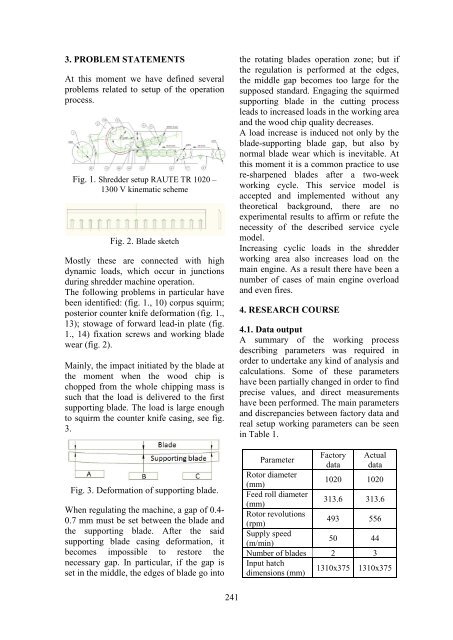
3. PROBLEM STATEMENTSAt this moment we have defined severalproblems related to setup of the operationprocess.Fig. 1. Shredder setup RAUTE TR 1020 –1300 V kinematic schemeFig. 2. Blade sketchMostly these are connected with highdynamic loads, which occur in junctionsduring shredder machine operation.The following problems in particular havebeen identified: (fig. 1., 10) corpus squirm;posterior counter knife deformation (fig. 1.,13); stowage of forward lead-in plate (fig.1., 14) fixation screws and working bladewear (fig. 2).Mainly, the impact initiated by the blade atthe moment when the wood chip ischopped from the whole chipping mass issuch that the load is delivered to the firstsupporting blade. The load is large enoughto squirm the counter knife casing, see fig.3.Fig. 3. Deformation of supporting blade.When regulating the machine, a gap of 0.4-0.7 mm must be set between the blade andthe supporting blade. After the saidsupporting blade casing deformation, itbecomes impossible to restore thenecessary gap. In particular, if the gap isset in the middle, the edges of blade go intothe rotating blades operation zone; but ifthe regulation is performed at the edges,the middle gap becomes too large for thesupposed standard. Engaging the squirmedsupporting blade in the cutting processleads to increased loads in the working areaand the wood chip quality decreases.A load increase is induced not only by theblade-supporting blade gap, but also bynormal blade wear which is inevitable. Atthis moment it is a common practice to usere-sharpened blades after a two-weekworking cycle. This service model isaccepted and implemented without anytheoretical background, there are noexperimental results to affirm or refute thenecessity of the described service cyclemodel.Increasing cyclic loads in the shredderworking area also increases load on themain engine. As a result there have been anumber of cases of main engine overloadand even fires.4. RESEARCH COURSE4.1. Data outputA summary of the working processdescribing parameters was required inorder to undertake any kind of analysis andcalculations. Some of these parametershave been partially changed in order to findprecise values, and direct measurementshave been performed. The main parametersand discrepancies between factory data andreal setup working parameters can be seenin Table 1.ParameterFactorydataActualdataRotor diameter(mm)1020 1020Feed roll diameter(mm)313.6 313.6Rotor revolutions(rpm)493 556Supply speed(m/min)50 44Number of blades 2 3Input hatchdimensions (mm)1310x375 1310x375241