ENGINEERING FOR RURAL DEVELOPMENT Jelgava, 26.-27.05.2011.humidity sensors, psychrometer, thermoanemometers, air flow, comfort index measurement in roomconditions, WBGT measurement, measuring thermal transmittance and heart flow for buildingphysics, sensors for measuring moisture in materials, surface temperature, soil humidity measurement,global radiation, light, luminous intensity, gas concentration in air (oxygen, carbon dioxide, carbonmonoxide, ammonia, hydrogen sulphide, etc.The student projects are based on real dimensions <strong>of</strong> the existing buildings or machines and theneeded simplifications are made to the corresponding geometries and models. The students are led touse the OpenFoam s<strong>of</strong>tware for solving them. Some projects are also solved using the Fluent and thecomparison <strong>of</strong> the results for such cases is done and discussed.The geometry which corresponds to the transversal shape <strong>of</strong> the broiler house [5] can be seen atFigure 1. It is a rectangle with two inlets (windows on the right side) and one outlet (the ventilator onthe left side), it corresponds to a more generalized case <strong>of</strong> transversal ventilation which is <strong>of</strong>ten usedas a ventilation schema at animal houses.Fig. 1. Typical geometry used as a student project case: All distances are given in meters. The level<strong>of</strong> measurement is the height above the floor, where the measurement at real objects was made. Theheat source represents the heat generated by poultryIt has to be mentioned, that there are completely different needs for the ventilation system duringthe summer and winter period. During the winter, the internal space <strong>of</strong> the broiler house is heated byadditional heat sources and the amount <strong>of</strong> incoming fresh air has to be preheated before the fresh airreaches the zone <strong>of</strong> animals to prevent their undercooling. It means that the amount <strong>of</strong> the incoming airis relatively small and is limited by the critical values <strong>of</strong> humidity and pollutant (CO 2 , NH 3 )concentration. During the summer period the amount <strong>of</strong> air depends mainly on the maximumtemperature, which is reached at the zone <strong>of</strong> animals to prevent overheating <strong>of</strong> them.It is clear, that the shape <strong>of</strong> the flow field is influenced by many parameters, but one <strong>of</strong> the mostimportant is the direction <strong>of</strong> the incoming air stream. Therefore, the analysis <strong>of</strong> the temperature pr<strong>of</strong>ileat the level <strong>of</strong> measurement can be very important and can be done relatively easily with CFD and it isa typical exercise for students’ work.Fig. 2. OpenFoam toolbox structure: All data processing and manipulations can be done using a part<strong>of</strong> this toolbox either with benefits <strong>of</strong> external programs (e.g., mesh generators, visualisation products,user defined inputs <strong>of</strong> data ...)The structure <strong>of</strong> the OpenFoam s<strong>of</strong>tware can be seen in Figure 2. The OpenFoam geometrydefinition file is shown in Figure 3. It is clear, that the definition is a poor text file with the definition<strong>of</strong> points, edges and boundary parts. The physical properties, solver setup and other parameters <strong>of</strong> themodel have to be defined in a similar way. This attempt is not so user friendly, but is very useful, forunderstanding the problem and thinking about physical background <strong>of</strong> the given case. For example,21
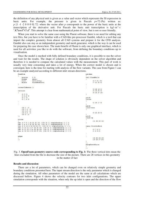
ENGINEERING FOR RURAL DEVELOPMENT Jelgava, 26.-27.05.2011.the definition <strong>of</strong> any physical unit is given as a value and vector which represents the SI expression inbasic units. For example, the pressure is given in Pascals p=72 (Pa) written as:p [1 -1 -2 0 0 0 0] 72; where the vector after p corresponds to the power <strong>of</strong> the basic units at thetranscription <strong>of</strong> the derivative unit. For Pascals the basic unit transcription is kg1·m -1·s -2 .K 0 kmol 0 A 0 cd 0 . This attempt is clear from mathematical point <strong>of</strong> view, but is not so user friendly.When you start to solve the same case using the Fluent s<strong>of</strong>tware, there is no need for editing anytext files, but you have to be familiar with a CAD-like pre-processor Gambit, which is a tool that canimport the complex geometry from almost all CAD systems and prepare it for the CFD analysis.Gambit also can stay as an independent geometry and mesh generator, which is the way it can be usedfor preparing the case shown here. The main benefit <strong>of</strong> Fluent is only one graphical interface, which isused for all activities you like to do with the s<strong>of</strong>tware, from defining the boundary conditions up tovisualisation.Once the model is meshed with fully defined boundary conditions, it is possible to run the solverand wait for the results. The shape <strong>of</strong> solution is obviously dependent on the solver algorithm andtherefore it is needed to compare the calculated values with the measurement. This part <strong>of</strong> work isusually very time consuming and takes a lot <strong>of</strong> energy. When the correct model is chosen and isconverged, here is the time for starting with analysis <strong>of</strong> the flow variants. The case from Figure 1 canbe an example analyzed according to different inlet stream directions.Fig. 3. OpenFoam geometry source code corresponding to Fig. 1: The three vertical dots mean thelines excluded from the file to decrease the size <strong>of</strong> the picture. There are 28 vertices in this geometryin the matter <strong>of</strong> factResults and discussionThere are a lot <strong>of</strong> parameters, which can be changed even on relatively simple geometry andboundary conditions presented here. The input stream direction is the only parameter which is changedduring the simulation. All other parameters <strong>of</strong> the model are the same at all calculations which arediscussed bellow. Figure 4 shows the velocity contours for two inlet configurations. The uppersimulation corresponds with the situation, when only the up inlet is open and the direction <strong>of</strong> the flow22