
You also want an ePaper? Increase the reach of your titles
YUMPU automatically turns print PDFs into web optimized ePapers that Google loves.
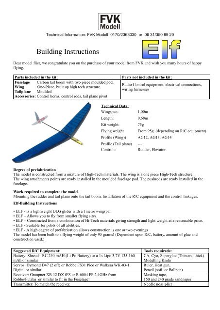
Technical Information: <strong>FVK</strong> <strong>Modell</strong> 0170/2363030 or 06 31/350 89 20<strong>Building</strong> <strong>Instructions</strong>Dear model flier, we congratulate you on the purchase of your model from <strong>FVK</strong> and wish you many hours of happyflying.Parts included in the kit:Fuselage Carbon tail boom with two piece moulded pod.Wing One-Piece, built up high tech structure.Tailplane MouldedAccessories: Control horns, control rods, tail plane pivotParts not included in the kit:Radio Control equipment, electrical connections,wiring harnessesTechnical Data:Wingspan: 1,00mLength: 0,68mKit weight:Flying weightProfile (Wing))75gFrom 95g (depending on R/C equipment)AG12, AG13, AG14Profile (Tail plane) ---Controls:Rudder, Elevator.Degree of prefabricationThe model is constructed from a mixture of High-Tech materials. The wing is a one piece High-Tech structure.The wing attachments points are ready installed in the moulded fuselage pod. The pushrods are ready installed in thefuselage.Work required to complete the model.Mounting the rudder and tail plane onto the tail boom. Installation of the R/C equipment and the control linkages.Elf-<strong>Building</strong> <strong>Instructions</strong>• ELF - Is a lightweight DLG glider with a 1metre wingspan.• ELF – Allows you to fly from smaller flying sites.• ELF – Constructed from a combination of Hi-Tech materials giving strength and light weight at a reasonable price.• ELF - Suitable for pilots of all abilities.• ELF - A high degree of prefabrication allows construction is one or two eveningsThe model has been built to a flying weight of only 95 grams! (Dependent upon R/C, battery, amount of glue andconstruction used.)Suggested R/C Equipment:Battery: Shread - RC 240 mAH (Li-Po Battery) or a 1s Lipo 3,7V 135-160mAh or similarServos: Dymond D47 (2 off) or Robbe FS31 Pico or Walkera WK-03-1Digital or similarReceiver: Graupner XR 12 DX iFS or R 6004 FF 2,4GHz fromRobbe/Futaba or similar to fit in the Fuselage!Transmitter: To match the receiver.Tools requireds:CA, Cyo, Superglue (Thin and thick)<strong>Modell</strong>ing KnifeRuler, Heat gun,Pencil (soft, or Ballpen)Masking tape,150 and 240 grade sandpaperNeedle nose plier
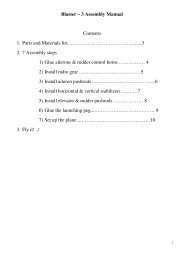
Installing the tail plane pivot and the rudder horn:1) Cut a slot in the center of the tail plane immediately behind the carbon spar (on the underside) for the V -Mount.Note:- Do not cut through the top surface of the tail plane. Caution: Take care not to damage the carbon spar!2) Disassemble the V-mount and insert the V-mount horn into the slot with the wide side pointing forwards.3) Glue the V-mount into the tail plane with thin Super Glue (Cyo - CA). Be careful not to flood the pivot holes!4) Reassemble the V-mount with the wide side pointing towards the leading edge.Rudder Horn5) Mark the position of the rudder horn on the rudder (50 mm from the base). Then cut the slot with a knife as shownin the picture below. Glue the horn into the rudder using thin Super glue.Fin/Rudder assembly:1) Insert the fin into the slot in the tail boom and align so the hinge line is perpendicular with the tail boom, carefullyglue using CA on both sides.TailplaneWing2) Fit the Tail plane and V-Mount to the tailboom and adjust the tailplane so it is perpendicular to the fin.3) Check the tailplane for free movement, at maximum throw up and down it shouldn’t foul anything.4) Fit the wing to the fuselage pod with the screws provided. Check the alignement of the fin and tailplane to the wingand each other (see photo) then carefully and accurately glue the V-Mount in place using super glue. Take care not toget glue on the V-Mount hinge.
Pushrod and servo installation:1) Attach the Tailplane pushrod to the V-Mount. Note:- The last pushrod guide is glued to the V-Mount this keeps theL shaped wire in place in the V-Mount.2) Attach the Rudder pushrod to the rudder horn.3) Remove the mounting lugs from the servos and roughen the bonding area with sandpaper. Wrap the servos inKevlar thread and glue the servos in place using CA as shown in the picture below. Be sure that the nose cone doesnot foul the servos.4) Switch the R/C on and set the servos to neutral.5) Cut the pushrods to length and connect them to the rudder and elevator servos with the Z bend wires and tubes, gluethe tubes to the pushrods using CA, cover with shrink tubing and carefully shrink with a heat gun.6) Remove the servo plugs in order to feed the cables under the fuselage pylon. Note:- check for the correct polaritywhen you replace the plugs!7) Fit the receiver and battery in the fuselage pod as shown below.Receiver Lipo – hold in placewith tapeRudder and Elevator servosReceiverPlace the R/C components in th efuselage pod as shown above.Drill holes for the receiver antennaFix the Bowden tubes to the inside of the fuselage, pack out tocorrect alignment with scrap balsa or foam.
Installation of the Throwing Peg1) Cut and sand the throwing peg to a shape that is comfortable for you.2) Identify which wing the peg will be fitted to suit your throwing style. (For right handed throwers fit the peg to theleft hand wing)3) Fill the slot in the wing tip with Thick CA.4) Slide the Throwing Peg into the wing tip slot and fill any gaps with thick CA.5) The slot in the opposite wing can be filled with thick CA. Additional weight can be added if necessary to balencethe wing laterally .CG location and control movements.1) The centre of Gravety (CG) is located 80-85 mm behind the leading edge of the wing.The CG can normally be achieved by moving the battery within the fuselage. Additional lead will increase weight.Experienced pilots may wish move the CG slightly rearward to suit their flying style. Do this with caution.2) Programme the transmitter to give the following control throws:-Rudder – Set as much left and right throw as possible, at least 20mm on each side.Elevator - At neutral the tailplane should be horizontal with the tail boom. Up = 9 mm, Down 9 mm.Check all of the control throws, the programming on the transmitter, check all controls and check the CG before goingflying!<strong>FVK</strong> cannot accept any responsibility or liability for damage caused in any way, to property or persons, bythe use of our products. It is the sole responsibility of the owner to ensure the safe use of our products.